EP3267221A2 - Rekonfigurierbare hf-front-end und gruppenantennen zur radarbetriebsartumschaltung - Google Patents
Rekonfigurierbare hf-front-end und gruppenantennen zur radarbetriebsartumschaltung Download PDFInfo
- Publication number
- EP3267221A2 EP3267221A2 EP17176118.2A EP17176118A EP3267221A2 EP 3267221 A2 EP3267221 A2 EP 3267221A2 EP 17176118 A EP17176118 A EP 17176118A EP 3267221 A2 EP3267221 A2 EP 3267221A2
- Authority
- EP
- European Patent Office
- Prior art keywords
- antennas
- radar
- subset
- mode
- antenna
- Prior art date
- Legal status (The legal status is an assumption and is not a legal conclusion. Google has not performed a legal analysis and makes no representation as to the accuracy of the status listed.)
- Ceased
Links
Images


Classifications
-
- G—PHYSICS
- G01—MEASURING; TESTING
- G01S—RADIO DIRECTION-FINDING; RADIO NAVIGATION; DETERMINING DISTANCE OR VELOCITY BY USE OF RADIO WAVES; LOCATING OR PRESENCE-DETECTING BY USE OF THE REFLECTION OR RERADIATION OF RADIO WAVES; ANALOGOUS ARRANGEMENTS USING OTHER WAVES
- G01S7/00—Details of systems according to groups G01S13/00, G01S15/00, G01S17/00
- G01S7/02—Details of systems according to groups G01S13/00, G01S15/00, G01S17/00 of systems according to group G01S13/00
- G01S7/40—Means for monitoring or calibrating
- G01S7/4004—Means for monitoring or calibrating of parts of a radar system
-
- G—PHYSICS
- G01—MEASURING; TESTING
- G01S—RADIO DIRECTION-FINDING; RADIO NAVIGATION; DETERMINING DISTANCE OR VELOCITY BY USE OF RADIO WAVES; LOCATING OR PRESENCE-DETECTING BY USE OF THE REFLECTION OR RERADIATION OF RADIO WAVES; ANALOGOUS ARRANGEMENTS USING OTHER WAVES
- G01S13/00—Systems using the reflection or reradiation of radio waves, e.g. radar systems; Analogous systems using reflection or reradiation of waves whose nature or wavelength is irrelevant or unspecified
- G01S13/88—Radar or analogous systems specially adapted for specific applications
- G01S13/93—Radar or analogous systems specially adapted for specific applications for anti-collision purposes
- G01S13/931—Radar or analogous systems specially adapted for specific applications for anti-collision purposes of land vehicles
-
- G—PHYSICS
- G01—MEASURING; TESTING
- G01S—RADIO DIRECTION-FINDING; RADIO NAVIGATION; DETERMINING DISTANCE OR VELOCITY BY USE OF RADIO WAVES; LOCATING OR PRESENCE-DETECTING BY USE OF THE REFLECTION OR RERADIATION OF RADIO WAVES; ANALOGOUS ARRANGEMENTS USING OTHER WAVES
- G01S7/00—Details of systems according to groups G01S13/00, G01S15/00, G01S17/00
- G01S7/02—Details of systems according to groups G01S13/00, G01S15/00, G01S17/00 of systems according to group G01S13/00
- G01S7/027—Constructional details of housings, e.g. form, type, material or ruggedness
-
- H—ELECTRICITY
- H01—ELECTRIC ELEMENTS
- H01Q—ANTENNAS, i.e. RADIO AERIALS
- H01Q21/00—Antenna arrays or systems
- H01Q21/06—Arrays of individually energised antenna units similarly polarised and spaced apart
-
- H—ELECTRICITY
- H01—ELECTRIC ELEMENTS
- H01Q—ANTENNAS, i.e. RADIO AERIALS
- H01Q21/00—Antenna arrays or systems
- H01Q21/06—Arrays of individually energised antenna units similarly polarised and spaced apart
- H01Q21/061—Two dimensional planar arrays
-
- H—ELECTRICITY
- H01—ELECTRIC ELEMENTS
- H01Q—ANTENNAS, i.e. RADIO AERIALS
- H01Q25/00—Antennas or antenna systems providing at least two radiating patterns
- H01Q25/002—Antennas or antenna systems providing at least two radiating patterns providing at least two patterns of different beamwidth; Variable beamwidth antennas
-
- H—ELECTRICITY
- H01—ELECTRIC ELEMENTS
- H01Q—ANTENNAS, i.e. RADIO AERIALS
- H01Q3/00—Arrangements for changing or varying the orientation or the shape of the directional pattern of the waves radiated from an antenna or antenna system
- H01Q3/24—Arrangements for changing or varying the orientation or the shape of the directional pattern of the waves radiated from an antenna or antenna system varying the orientation by switching energy from one active radiating element to another, e.g. for beam switching
-
- G—PHYSICS
- G01—MEASURING; TESTING
- G01S—RADIO DIRECTION-FINDING; RADIO NAVIGATION; DETERMINING DISTANCE OR VELOCITY BY USE OF RADIO WAVES; LOCATING OR PRESENCE-DETECTING BY USE OF THE REFLECTION OR RERADIATION OF RADIO WAVES; ANALOGOUS ARRANGEMENTS USING OTHER WAVES
- G01S13/00—Systems using the reflection or reradiation of radio waves, e.g. radar systems; Analogous systems using reflection or reradiation of waves whose nature or wavelength is irrelevant or unspecified
- G01S13/02—Systems using reflection of radio waves, e.g. primary radar systems; Analogous systems
- G01S2013/0236—Special technical features
- G01S2013/0245—Radar with phased array antenna
-
- G—PHYSICS
- G01—MEASURING; TESTING
- G01S—RADIO DIRECTION-FINDING; RADIO NAVIGATION; DETERMINING DISTANCE OR VELOCITY BY USE OF RADIO WAVES; LOCATING OR PRESENCE-DETECTING BY USE OF THE REFLECTION OR RERADIATION OF RADIO WAVES; ANALOGOUS ARRANGEMENTS USING OTHER WAVES
- G01S13/00—Systems using the reflection or reradiation of radio waves, e.g. radar systems; Analogous systems using reflection or reradiation of waves whose nature or wavelength is irrelevant or unspecified
- G01S13/88—Radar or analogous systems specially adapted for specific applications
- G01S13/93—Radar or analogous systems specially adapted for specific applications for anti-collision purposes
- G01S13/931—Radar or analogous systems specially adapted for specific applications for anti-collision purposes of land vehicles
- G01S2013/9327—Sensor installation details
- G01S2013/93271—Sensor installation details in the front of the vehicles
-
- G—PHYSICS
- G01—MEASURING; TESTING
- G01S—RADIO DIRECTION-FINDING; RADIO NAVIGATION; DETERMINING DISTANCE OR VELOCITY BY USE OF RADIO WAVES; LOCATING OR PRESENCE-DETECTING BY USE OF THE REFLECTION OR RERADIATION OF RADIO WAVES; ANALOGOUS ARRANGEMENTS USING OTHER WAVES
- G01S13/00—Systems using the reflection or reradiation of radio waves, e.g. radar systems; Analogous systems using reflection or reradiation of waves whose nature or wavelength is irrelevant or unspecified
- G01S13/88—Radar or analogous systems specially adapted for specific applications
- G01S13/93—Radar or analogous systems specially adapted for specific applications for anti-collision purposes
- G01S13/931—Radar or analogous systems specially adapted for specific applications for anti-collision purposes of land vehicles
- G01S2013/9327—Sensor installation details
- G01S2013/93272—Sensor installation details in the back of the vehicles
-
- H—ELECTRICITY
- H01—ELECTRIC ELEMENTS
- H01Q—ANTENNAS, i.e. RADIO AERIALS
- H01Q1/00—Details of, or arrangements associated with, antennas
- H01Q1/27—Adaptation for use in or on movable bodies
- H01Q1/32—Adaptation for use in or on road or rail vehicles
- H01Q1/3208—Adaptation for use in or on road or rail vehicles characterised by the application wherein the antenna is used
- H01Q1/3233—Adaptation for use in or on road or rail vehicles characterised by the application wherein the antenna is used particular used as part of a sensor or in a security system, e.g. for automotive radar, navigation systems
-
- H—ELECTRICITY
- H01—ELECTRIC ELEMENTS
- H01Q—ANTENNAS, i.e. RADIO AERIALS
- H01Q21/00—Antenna arrays or systems
- H01Q21/0006—Particular feeding systems
-
- H—ELECTRICITY
- H01—ELECTRIC ELEMENTS
- H01Q—ANTENNAS, i.e. RADIO AERIALS
- H01Q21/00—Antenna arrays or systems
- H01Q21/06—Arrays of individually energised antenna units similarly polarised and spaced apart
- H01Q21/061—Two dimensional planar arrays
- H01Q21/065—Patch antenna array
Definitions
- the present disclosure is generally related to remote sensing and, more particularly, to a reconfigurable radio frequency (RF) front end and antenna arrays for radar mode switching.
- RF radio frequency
- Automotive radars are a key component of Advanced Driver Assistance Systems (ADAS) and can be classified as ultra-short-range radars (USRR), short-range radars (SRR), medium-range radars (MRR) and long-range radars (LRR).
- USRR ultra-short-range radars
- SRR short-range radars
- MRR medium-range radars
- LRR long-range radars
- Each class of radars requires a dedicated module design, as different classes of radars correspond to different antenna arrays with different gains, different field of views (FOV), beam patterns and the like.
- the form factor, such as size, of radar systems is usually dominated by antennas.
- TX transmitter
- RX receiver
- switching between or among different antenna arrays for a given radar system is costly, at least in terms of size, power and performance.
- additional and dedicated switches are needed with high loss at millimeter wave (mmWave) frequencies, e.g., a few dB loss per switch.
- mmWave millimeter wave
- interconnect loss there is also interconnect loss, and adjacent antenna spacing is constrained.
- An objective of the present disclosure is to propose various novel concepts and schemes pertaining to reconfigurable RF front end and antenna arrays for radar mode switching.
- Implementations in accordance with the present disclosure support multi-class radar in one module with less total antenna elements.
- Implementations in accordance with the present disclosure may utilize a radar chip with mode switch, and such radar chip has numerous advantages over designs with dedicated external switches.
- a radar chip with mode switch in accordance with the present disclosure has less loss, consumes less power, has better performance, has a smaller size, and is associated with lower cost compared to designs with dedicated external switches.
- a method may involve a processor associated with a radar system selecting a mode of a plurality of modes in which to operate the radar system.
- the method may also involve the processor controlling the radar system to operate in the selected mode by utilizing a plurality of antennas in a respective configuration of a plurality of configurations of the antennas which corresponds to the selected mode.
- Each configuration of the plurality of configurations of the antennas may result in respective antenna characteristics.
- Each configuration of the plurality of configurations of the antennas may utilize a respective number of antennas of the plurality of antennas.
- a method may involve a processor associated with a radar system controlling the radar system to operate in a first mode of a plurality of modes by utilizing a plurality of antennas in a first configuration of a plurality of configurations of the antennas.
- the method may also involve the processor determining a need to switch the radar system from operating in the first mode to a second mode of the plurality of modes.
- the method may further involve the processor controlling the radar system to operate in the second mode by utilizing the plurality of antennas in a second configuration of the plurality of configurations of the antennas.
- Each configuration of the plurality of configurations of the antennas may result in respective antenna characteristics such that first antenna characteristics of the first configuration differ from second antenna characteristics of the second configuration.
- an apparatus may include a plurality of antennas, one or more radar chips, and a processor.
- the plurality of antennas may be operable in one of a plurality of configurations for a respective one of a plurality of modes of radar operations.
- the plurality of antennas may include one or more in-package antennas and one or more external antennas.
- Each of the one or more radar chips may respectively include a transmitter and a receiver.
- Each of the one or more radar chips may be electrically coupled to a respective antenna of the plurality of antennas.
- the processor may be operatively coupled to the one or more radar chips to control the one or more radar chips to perform the radar operations.
- the processor may include a mode switching circuit and a control circuit.
- the mode switching circuit may select one of the plurality of modes of radar operations.
- the control circuit may control the one or more radar chips to operate in the selected mode by utilizing the plurality of antennas in a respective configuration of the plurality of configurations of the antennas which corresponds to the selected mode.
- Each configuration of the plurality of configurations of the antennas may result in respective antenna characteristics.
- Each configuration of the plurality of configurations of the antennas may utilize a respective number of antennas of the plurality of antennas.
- the one or more in-package antennas may be enclosed in a package with the one or more radar chips.
- the one or more external antennas may be external to the package.
- different classes of radar utilize different numbers of antenna elements or antennas of a multi-class radar. Accordingly, antenna elements may be planned and reused.
- the proposed scheme enables flexible configuration of a number of antennas, antenna elements and/or antenna arrays. That is, for a given number of antennas, antenna elements and/or antenna arrays in a multi-class radar system in accordance with the present disclosure, different configurations of the antennas, antenna elements and/or antenna arrays may correspond to different modes of radar operations.
- different number of transmitters and different number of antennas utilized for transmitting
- different number of receivers and different number of antennas utilized for receiving
- a configuration of one TX and one RX a configuration of one TX and two RX's, or a configuration of one TX and three RX's may be utilized.
- a configuration of one TX and three RX's or a configuration of two TX's and four RX's may be utilized.
- a configuration of one TX and four or more RX's may be utilized. That is, regardless of the class of radar, select antennas may be utilized as TX antenna(s) or RX antenna(s).
- one or more antennas may be in-package antennas enclosed in a package with corresponding radar chip(s), and one or more antennas may be external antennas external to the package.
- the in-package antennas may be part of the antenna array of the radar system on a printed circuit board (PCB).
- results of radar measurement over multiple frames/modes may be merged to provide a larger antenna array as well as multi-characteristic data to enhance signal and data processing.
- implementations in accordance with the present disclosure may be able to have dedicated mmWave switch if needed.
- each TX antenna and RX antenna may be swapped out with another antenna to enable advanced signal processing.
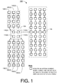
- FIG. 1 illustrates an example radar system 100 designed for reconfigurable RF front end and antenna arrays in accordance with an implementation of the present disclosure.
- an individual antenna element may constitute an antenna.
- An array of multiple antenna elements may constitute an antenna.
- multiple arrays of antenna elements may also constitute an antenna. Accordingly, such antennas may have different antenna characteristics such as gain, FOV, power consumption, performance and the like.
- antennas 110(1), 110(2), 110(3), 110(4), 120(1), 120(2), 120(3), 130(1), 130(2), 130(3), 130(4) and 140 are in-package antennas with very low gain and very large FOV.
- Antennas 120(1) - 120(3) are external antennas disposed on a PCB with low gain and large FOV.
- Antennas 130(1) - 130(4) are also external antennas disposed on the same or a different PCB as antennas 120(1) - 120(3) with medium gain and medium FOV.
- Antenna 140 is another external antenna disposed on the same or a different PCB as antennas 120(1) - 120(3) with high gain and small FOV.
- these twelve antennas have different sizes and are unsymmetrical.
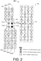
- FIG. 2 illustrates an example configuration 200 of radar system 100 in accordance with an implementation of the present disclosure.
- antennas 110(1) - 110(4), 120(1) - 120(3), 130(1) - 130(4) and 140 are utilized in a first configuration for radar system 100 to be in a first mode of radar operation as an USRR class of radar.
- two TX antennas and two RX antennas are utilized and active in this configuration.
- in-package antennas 110(1) and 110(3) are utilized as TX antennas that are electrically coupled to corresponding transmitters (not shown) to transmit radar signals.
- in-package antennas 110(2) and 110(4) are utilized as RX antennas that are electrically coupled to corresponding receivers (not shown) to receive reflected radar signals.
- the remaining antennas of radar system 100 are unused and stay inactive.
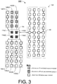
- FIG. 3 illustrates an example configuration 300 of radar system 100 in accordance with an implementation of the present disclosure.
- antennas 110(1) - 110(4), 120(1) - 120(3), 130(1) - 130(4) and 140 are utilized in a second configuration for radar system 100 to be in a second mode of radar operation as an SRR class of radar.
- two TX antennas and four RX antennas are utilized and active in this configuration.
- external antennas 120(2) and 120(3) are utilized as TX antennas that are electrically coupled to corresponding transmitters (not shown) to transmit radar signals.
- in-package antennas 110(1) - 110(4) are utilized as RX antennas that are electrically coupled to corresponding receivers (not shown) to receive reflected radar signals.
- the remaining antennas of radar system 100 are unused and stay inactive.
- elements of the TX antenna array(s) need not be the same as the RX antenna array(s).
- a RX antenna array may be formed by antennas 120(1) - 120(4) plus antenna 130(3) simultaneously to "tune" the antenna characteristics (e.g, shapes of radiation pattern and FOV).
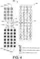
- FIG. 4 illustrates an example configuration 400 of radar system 100 in accordance with an implementation of the present disclosure.
- antennas 110(1) - 110(4), 120(1) - 120(3), 130(1) - 130(4) and 140 are utilized in a third configuration for radar system 100 to be in a third mode of radar operation as an MRR class of radar.
- three TX antennas and four RX antennas are utilized and active in this configuration.
- external antennas 120(1) - 120(3) are utilized as TX antennas that are electrically coupled to corresponding transmitters (not shown) to transmit radar signals.
- external antennas 130(1) - 130(4) are utilized as RX antennas that are electrically coupled to corresponding receivers (not shown) to receive reflected radar signals.
- the remaining antennas of radar system 100 are unused and stay inactive.
- FIG. 5 illustrates an example configuration 500 of radar system 100 in accordance with an implementation of the present disclosure.
- antennas 110(1) - 110(4), 120(1) - 120(3), 130(1) - 130(4) and 140 are utilized in a fourth configuration for radar system 100 to be in a fourth mode of radar operation as an MRR class of radar.
- two TX antennas and four RX antennas are utilized and active in this configuration.
- in-package antennas 110(1) - 110(4) and external antennas 120(2) and 120(3) are utilized as TX antennas that are electrically coupled to corresponding transmitters (not shown) to transmit radar signals.
- external antennas 130(1) - 130(4) are utilized as RX antennas that are electrically coupled to corresponding receivers (not shown) to receive reflected radar signals.
- the remaining antennas of radar system 100 are unused and stay inactive.
- a first TX antenna is formed by in-package antennas 110(1) and 110(3) together with external antenna 120(2)
- a second TX antenna is formed by in-package antennas 110(2) and 110(4) together with external antenna 120(3).
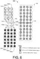
- FIG. 6 illustrates an example configuration 600 of radar system 100 in accordance with an implementation of the present disclosure.
- antennas 110(1) - 110(4), 120(1) - 120(3), 130(1) - 130(4) and 140 are utilized in a fifth configuration for radar system 100 to be in a fifth mode of radar operation as an LRR class of radar.
- one TX antenna and four RX antennas are utilized and active in this configuration.
- external antenna 140 is utilized as a TX antenna that is electrically coupled to a corresponding transmitter (not shown) to transmit radar signals.
- external antennas 130(1) - 130(4) are utilized as RX antennas that are electrically coupled to corresponding receivers (not shown) to receive reflected radar signals.
- the remaining antennas of radar system 100 are unused and stay inactive.
- implementations in accordance with the present disclosure may flexibly perform radar class switching from one class of radar to another. This may be achieved by (1) activating respective transmitter(s) and receiver(s) corresponding to each class of radar and (2) utilizing a respective configuration of antennas corresponding to each class of radar.
- the antennas utilized may be solely in-package antennas, solely externa antennas, or a combination of one or more in-package antennas and one or more external antennas.
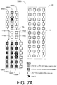
- FIG. 7A and FIG. 7B illustrate an example scenario 700 of reconfiguration of radar system 100 in accordance with an implementation of the present disclosure.
- antennas 110(1) - 110(4), 120(1) - 120(3), 130(1) - 130(4) and 140 may be initially utilized in a particular configuration for radar system 100 to be in a particular mode of radar operation having one TX antenna and three RX antennas utilized and active in this configuration.
- external antenna 120(2) is utilized as a TX antenna to transmit radar signals
- external antennas 130(1) - 130(3) are utilized as RX antennas to receive reflected radar signals.
- the TX path and one of the RX paths fail during operation. That is, there is a fault in each of antenna 120(2) and antenna 130(3).
- a different antenna may be utilized to replace each of the failed TX antenna and the failed RX antenna.
- antenna 120(3) is activated to replace antenna 120(2), which has failed.
- antenna 130(4) is activated to replace antenna 130(3), which also has failed.
- antenna 120(3) may be similar or identical to antenna 120(2) in terms of form factor, antenna characteristics for transmission of radar signals (e.g., gain and FOV) may remain relatively unchanged.
- antenna 130(4) may be similar or identical to antenna 130(3) in terms of form factor, antenna characteristics for receiving of reflected radar signals (e.g., gain and FOV) may remain relatively unchanged.
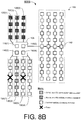
- FIG. 8A and FIG. 8B illustrate an example scenario 800 of reconfiguration of radar system 100 in accordance with an implementation of the present disclosure.
- antennas 110(1) - 110(4), 120(1) - 120(3), 130(1) - 130(4) and 140 may be initially utilized in a particular configuration for radar system 100 to be in a particular mode of radar operation having one TX antenna and three RX antennas utilized and active in this configuration.
- external antenna 120(2) is utilized as a TX antenna to transmit radar signals
- external antennas 130(1) - 130(3) are utilized as RX antennas to receive reflected radar signals.
- two of the RX paths fail during operation. That is, there is a fault in each of antenna 130(1) and antenna 130(3).
- the TX path(s) and RX path(s) may be swapped to other functional (non-faulty) path(s) in that a different antenna may be utilized to replace each of the failed TX antenna and the failed RX antenna.
- antennas 120(1) - 120(3) are activated to replace antennas 130(1) - 130(3) as the TX paths.
- antenna 130(2) is activated to replace antenna 120(2) as part of the swap.
- FIG. 9A illustrates an example apparatus 900A in accordance with an implementation of the present disclosure.
- Apparatus 900A may be an example implementation of radar system 100.
- Apparatus 900A may perform various functions, operations and/or tasks to implement concepts, schemes, techniques, processes and methods described herein pertaining to reconfigurable RF front end and antenna arrays for radar mode switching in accordance with the present disclosure, including those described with respect to some or all of FIG. 1 - FIG. 8A / 8B as well as processes 1200 and 1300 described below.
- Apparatus 900A may be a part of an electronic apparatus or a transportation vehicle such as an automobile.
- apparatus 900A may be implemented in an autonomous vehicle.
- apparatus 900A may be implemented, at least partly, in the form of one or more integrated-circuit (IC) chips such as, for example and not limited to, one or more single-core processors, one or more multi-core processors, or one or more complex-instruction-set-computing (CISC) processors.
- IC integrated-circuit
- Apparatus 900A may include at least some of those components shown in FIG. 9A .
- apparatus 900A may include at least a processor 910.
- apparatus 900A may include one or more radar chips such as radar chips 920(1) - 920(M+N), where each of M and N is a positive integer. It is also noteworthy that, although illustrated as multiple separate and individual radar chips, in some implementations some or all of radar chips 920(1) - 920(M+N) may be implemented in a single radar chip (and in such case they are transceiver circuits or transceiver elements, instead of individual radar chips).
- Radar chips/transceiver circuits 920(1) - 920(M+N) may be controlled/configured by processor 910 to transmit or receive with different signal phases to form and steer RF beams.
- Apparatus 900A may also include one or more in-package antennas such as antennas 930(1) - 930(M). Each of antennas 930(1) - 930(M) may correspond to and may be electrically coupled to a respective one of radar chips 920(1) - 920(M+N), such as one of radar chips 920(1) - 920(M). In the example shown in FIG.
- apparatus 900A may further include one or more external antennas such as antennas 940(1) - 940(N).
- antennas 940(1) - 940(N) may correspond to and may be electrically coupled to a respective one of radar chips 920(1) - 920(M+N), such as one of radar chips 920(M+1) - 920(M+N).
- Antennas 940(1) - 940(N) are external to package 905 and may be disposed together or separately on one or more objects such as, for example, a printed circuit board (PCB).
- PCB printed circuit board
- a radar chip/transceiver circuit and its in-package antenna there may be an additional switch 935 to couple the in-package antenna (e.g., 930(1)) to outside of package 905 to form connection(s) with external antenna(s) such as the example shown in FIG. 5 .
- the in-package antennas 930(1) - 930(M) (which may be on-chip antennas) and external antennas 940(1) - 940(N) (which may be off-chip antennas) may be coupled to the same transceiver/radar chip in addition to the already described condition with multiple transceivers/radar chips.
- the on-chip antennas and off-chip antennas may be placed or otherwise designed together to properly form an antenna array.
- Each of radar chips 920(1) - 920(M+N) may respectively include a TX 962, a RX 964, a duplexer or switch 966 and a control unit 968.
- Switch 966 may be electrically coupled between TX 962 and RX 964, and may be controlled by control unit 968 to electrically connect either TX 962 or RX 964 to a respective antenna at any given time. That is, either TX 962 or RX 964, but not both, may be electrically connected to the respective antenna through switch 966 unless switch 966 was replaced with a circulator.
- Control unit 968 may activate (turn on) or deactivate (turn off) TX 962 and RX 964 alternatively while controlling switch 966 to switch between TX 962 and RX 964.
- Switch 966 may be an implicit switch embedded in TX 962 and RX 964 as enable/disable circuitries.
- the respective radar chip may function as a transmitter when TX 962 is turned on and electrically connected to the respective antenna through switch 966 with RX 964 turned off.
- the respective radar chip may function as a receiver when RX 964 is turned on and electrically connected to the respective antenna through switch 966 with TX 962 turned off.
- Each of radar chips 920(1) - 920(M+N) may also include a mixer 974 and/or a radar signal processor 970.
- Apparatus 900A may include a signal source 972 that generates and provides a radar signal for transmission via TX 962 of each of radar chips 920(1) - 920(M+N).
- Radar signal processor 970 may receive a signal, representative of the reflected radar signal, from RX 964 via mixer 974 to process the signal. Alternatively, either or both of mixer 974 and radar signal processor 970 may be external to the radar chip.
- processor 910 may be implemented in the form of one or more single-core processors, one or more multi-core processors, or one or more CISC processors. That is, even though a singular term "a processor" is used herein to refer to processor 910, processor 910 may include multiple processors in some implementations and a single processor in other implementations in accordance with the present disclosure.
- processor 910 may be implemented in the form of hardware (and, optionally, firmware) with electronic components including, for example and without limitation, one or more transistors, one or more diodes, one or more capacitors, one or more resistors, one or more inductors, one or more memristors and/or one or more varactors that are configured and arranged to achieve specific purposes in accordance with the present disclosure.
- processor 910 is a special-purpose machine specifically designed, arranged and configured to perform specific tasks including reconfigurable RF front end and antenna arrays for radar mode switching in accordance with various implementations of the present disclosure.
- Processor 910 may include non-generic and specially-designed hardware circuits that are designed, arranged and configured to perform specific tasks pertaining to reconfigurable RF front end and antenna arrays for radar mode switching in accordance with various implementations of the present disclosure.
- processor 910 may include a mode switching circuit 912 and a control circuit 914 that, together, perform specific tasks and functions to render reconfigurable RF front end and antenna arrays for radar mode switching in accordance with various implementations of the present disclosure.
- antennas 930(1) - 930(M) and antennas 940(1) - 940(N) may be operable in one of a plurality of configurations for a respective one of a plurality of modes of radar operations.
- Processor 910 may be operably coupled to radar chips 920(1) - 920(M+N) to control radar chips 920(1) - 920(M+N) to perform the radar operations.
- processor 910 may control radar chips 920(1) - 920(M+N) to operate, by utilizing respective antenna(s) of antennas 930(1) - 930(M) and antennas 940(1) - 940(N), in one of the following modes at any given time: an ultra-short-range radar (USRR) mode, a short-range radar (SRR) mode, a medium-range radar (MRR) mode and a long-range radar (LRR) mode.
- USRR ultra-short-range radar
- SRR short-range radar
- MRR medium-range radar
- LRR long-range radar
- mode switching circuit 912 of processor 910 may select one of the plurality of modes of radar operations.
- Control circuit 914 of processor 910 may control radar chips 920(1) - 920(M+N) to operate in the selected mode by utilizing antennas 930(1) - 930(M) and antennas 940(1) - 940(N) in a respective configuration of the plurality of configurations which corresponds to the selected mode.
- each configuration of the plurality of configurations of the antennas may result in respective antenna characteristics.
- each configuration of the plurality of configurations of the antennas may utilize a respective number of antennas of the plurality of antennas.
- a configuration of one TX and one RX a configuration of one TX and two RX's, or a configuration of one TX and three RX's may be utilized.
- a configuration of one TX and three RX's or a configuration of two TX's and four RX's may be utilized.
- a configuration of one TX and four or more RX's may be utilized. That is, regardless of the mode or class of radar, select ones of antennas 930(1) - 930(M) and antennas 940(1) - 940(N) may be utilized as TX antenna(s) or RX antenna(s).
- control circuit 914 may perform a number of operations. For instance, control circuit 914 may utilize a first subset of one or more antennas of antennas 930(1) - 930(M) and antennas 940(1) - 940(N) to transmit radar signals. Control circuit 914 may also utilize a second subset of one or more antennas of antennas 930(1) - 930(M) and antennas 940(1) - 940(N) to receive reflected radar signals.
- Control circuit 914 may detect a fault in the first subset or the second subset. As a result of the detecting, control circuit 914 may perform either of the following: (1) utilizing a third subset of one or more antennas of antennas 930(1) - 930(M) and antennas 940(1) - 940(N) to transmit the radar signals responsive to the fault being associated with at least one antenna in the first subset; or (2) utilizing a fourth subset of one or more antennas of antennas 930(1) - 930(M) and antennas 940(1) - 940(N) to receive the reflected radar signals responsive to the fault being associated with at least one antenna in the second subset.
- the utilizing of the first subset may result in first antenna characteristics for transmitting the radar signals
- the utilizing of the second subset may result in second antenna characteristics for receiving the reflected radar signals
- the utilizing of the third subset may result in third antenna characteristics for transmitting the radar signals
- the utilizing of the fourth subset may result in fourth antenna characteristics for receiving the reflected radar signals.
- the third antenna characteristics may approximate (e.g., substantially equal to) the first antenna characteristics.
- the fourth antenna characteristics may approximate (e.g., substantially equal to) the second antenna characteristics.
- a first antenna of antennas 930(1) - 930(M) and antennas 940(1) - 940(N) may be in both the second subset and the third subset.
- a second antenna of antennas 930(1) - 930(M) and antennas 940(1) - 940(N) may be in both the first subset and the fourth subset.
- An example scenario is illustrated in FIG. 8A and FIG. 8B .
- the respective antenna characteristics of each configuration of the plurality of configurations of the antennas may include respective values in terms of at least an antenna gain and a field of view.
- control circuit 914 may perform a number of operations for each mode of the plurality of modes. For instance, for each mode, control circuit 914 may activate a respective first number of transmitters (or radar chips) to transmit radar signals through a first subset of one or more antennas of antennas 930(1) - 930(M) and antennas 940(1) - 940(N) having the respective first number of antennas.
- control circuit 914 may activate a respective second number of receivers (or radar chips) to receive reflected radar signals through a second subset of one or more antennas of antennas 930(1) - 930(M) and antennas 940(1) - 940(N) having the respective second number of antennas.
- the respective first number for a first mode of the modes may differ from the respective first number for at least a second mode of the modes.
- the respective second number for the first mode of the modes may differ from the respective second number for at least a third mode of the modes.
- control circuit 914 may control radar chips 920(1) - 920(M+N) to operate in a first mode of a plurality of modes by utilizing antennas 930(1) - 930(M) and antennas 940(1) - 940(N) in a first configuration of a plurality of configurations.
- Mode switching circuit 912 may determine a need to switch radar chips 920(1) - 920(M+N) from operating in the first mode to a second mode of the plurality of modes.
- control circuit 914 may control radar chips 920(1) - 920(M+N) to operate in the second mode by utilizing antennas 930(1) - 930(M) and antennas 940(1) - 940(N) in a second configuration of the plurality of configurations.
- Each configuration of the plurality of configurations of the antennas may result in respective antenna characteristics such that first antenna characteristics of the first configuration differ from second antenna characteristics of the second configuration.
- the first antenna characteristics of the first configuration may differ from the second antenna characteristics of the second configuration in terms of an antenna gain, a field of view, or both.
- control circuit 914 may activate a first number of transmitters (or radar chips) to transmit radar signals through a first subset of one or more antennas of antennas 930(1) - 930(M) and antennas 940(1) - 940(N) having the first number of antennas.
- control circuit 914 may activate a second number of receivers (or radar chips) to receive reflected radar signals through a second subset of one or more antennas of antennas 930(1) - 930(M) and antennas 940(1) - 940(N) having the second number of antennas.
- control circuit 914 may activate a third number of transmitters (or radar chips) to transmit the radar signals through a third subset of one or more antennas of antennas 930(1) - 930(M) and antennas 940(1) - 940(N) having the third number of antennas.
- control circuit 914 may activate a fourth number of receivers (or radar chips) to receive the reflected radar signals through a fourth subset of one or more antennas of antennas 930(1) - 930(M) and antennas 940(1) - 940(N) having the fourth number of antennas.
- control circuit 914 may detect a fault in at least one of antennas 930(1) - 930(M) and antennas 940(1) - 940(N) in the second configuration utilized for radar operations. Consequently, control circuit 914 may control radar chips 920(1) - 920(M+N) to operate in the second mode by utilizing antennas 930(1) - 930(M) and antennas 940(1) - 940(N) in a third configuration of the plurality of configurations of the antennas.
- third antenna characteristics of the third configuration may approximate (e.g., substantially equal to) the second antenna characteristics of the second configuration. For instance, the gain and FOV of the third configuration may be similar or identical to the gain and FOV of the second configuration, even though different antennas may be utilized in the second configuration and the third configuration.
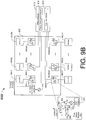
- FIG. 9B illustrates an example apparatus 900B in accordance with an implementation of the present disclosure.
- Apparatus 900B may be an example implementation of radar system 100.
- Apparatus 900B may perform various functions, operations and/or tasks to implement concepts, schemes, techniques, processes and methods described herein pertaining to reconfigurable RF front end and antenna arrays for radar mode switching in accordance with the present disclosure, including those described with respect to some or all of FIG. 1 - FIG. 8A / 8B as well as processes 1200 and 1300 described below.
- Apparatus 900B may be a part of an electronic apparatus or a transportation vehicle such as an automobile.
- apparatus 900B may be implemented in an autonomous vehicle.
- apparatus 900B may be implemented, at least partly, in the form of one or more IC chips such as, for example and not limited to, one or more single-core processors, one or more multi-core processors, or one or more CISC processors.
- Apparatus 900B may include at least some of those components shown in FIG. 9B .
- apparatus 900B may include at least a processor 910.
- apparatus 900B may include one or more radar chips such as radar chips 920(1) - 920(M+N), where each of M and N is a positive integer.
- Apparatus 900B may also include one or more in-package antennas such as antennas 930(1) - 930(M). Each of antennas 930(1) - 930(M) may correspond to and may be electrically coupled to a respective one of radar chips 920(1) - 920(M+N), such as one of radar chips 920(1) - 920(M).
- FIG. 9 the example shown in FIG.
- apparatus 900B may further include one or more external antennas such as antennas 940(1) - 940(N).
- Each of antennas 940(1) - 940(N) may correspond to and may be electrically coupled to a respective one of radar chips 920(1) - 920(M+N), such as one of radar chips 920(M+1) - 920(M+N).
- Antennas 940(1) - 940(N) are external to package 955 and may be disposed together or separately on one or more objects such as, for example, a PCB.
- Apparatus 900B differs from apparatus 900A in that processor 910 in apparatus 900B is external to package 955 while processor 910 in apparatus 900A is enclosed in package 905. Otherwise, description of the structure, functions, features and operations of apparatus 900A provided above also applies to apparatus 900B. Thus, in the interest of brevity and simplicity, detailed description of the structure and function of apparatus 900B is not provided to avoid redundancy.
- FIG. 10 illustrates an example automobile 1000 in accordance with an implementation of the present disclosure.
- Automobile 1000 may be a manually-operated vehicle operated by a human driver.
- automobile 1000 may be a vehicle that can be operated in a manual mode and an autonomous mode.
- automobile 1000 may be an autonomous vehicle that is fully automatic and does not require any manual operation.
- automobile 1000 may be equipped with a control system 1010 having a processor 1015 that controls one or more radar systems such as radar systems 1020, 1030 and 1040.
- processor 1015 and radar systems 1020, 1030 and 1040 may be an example implementation of radar system 100 and/or apparatus 900B, whether completely or partially.
- detailed description of the structure and function of each of processor 1015 and radar systems 1020, 1030 and 1040 is not provided to avoid redundancy.
- Processor 1015 may implement reconfigurable RF front end and antenna arrays for radar mode switching in accordance with the present disclosure.
- each of radar systems 1020, 1030 and 1040 may operate in a plurality of modes to function as a multi-class radar to provide various horizontal field of views and elevational field of views.
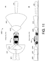
- FIG. 11 illustrates a demonstration 1100 various automotive radar field of views of automobile 1000 in accordance with an implementation of the present disclosure.
- each of the multiple radar systems 1020, 1030 and 1040 installed on automobile 1000 may operate in a plurality of modes to function as a multi-class radar to provide various horizontal field of views and elevational field of views. That is, each radar system on automobile 1000 may function as some or all of the following: an ultra-short-range radar (USRR), a short-range radar (SRR), a medium-range radar (MRR) and a long-range radar (LRR).
- USRR ultra-short-range radar
- SRR short-range radar
- MRR medium-range radar
- LRR long-range radar
- the front radar system (e.g., radar system 1020) may function as a multi-class radar as an USRR, an MRR and an LRR.
- each of the two rear radar systems (e.g., radar systems 1030 and 1040) may function as a multi-class radar as an USRR, an SRR and an MRR.
- FIG. 12 illustrates an example process 1200 in accordance with an implementation of the present disclosure.
- Process 1200 may represent an aspect of implementing the proposed concepts and schemes such as those described with respect to some or all of FIG. 1 - FIG. 11 . More specifically, process 1200 may represent an aspect of the proposed concepts and schemes pertaining to reconfigurable RF front end and antenna arrays for radar mode switching.
- Process 1200 may include one or more operations, actions, or functions as illustrated by one or more of blocks 1210 and 1220 as well as sub-blocks 1222 and 1224. Although illustrated as discrete blocks, various blocks of process 1200 may be divided into additional blocks, combined into fewer blocks, or eliminated, depending on the desired implementation. Moreover, the blocks/sub-blocks of process 1200 may be executed in the order shown in FIG.
- Process 1200 may be executed iteratively.
- Process 1200 may be implemented by or in apparatus 900A, apparatus 900B and automobile 1000 as well as any variations thereof.
- process 1200 may be implemented by or in apparatus 900A and/or apparatus 900B. Solely for illustrative purposes and without limiting the scope, process 1200 is described below in the context of apparatus 900A/900B implemented as radar system 100 in automobile 1000.
- Process 1200 may begin at block 1210.
- process 1200 may involve processor 910 selecting a mode of a plurality of modes in which to operate radar system 100. Process 1200 may proceed from 1210 to 1220.
- process 1200 may involve processor 910 controlling radar system 100 to operate in the selected mode by utilizing a plurality of antennas (e.g., antennas 110(1) - 110(4), 120(1) - 120(3), 130(1) - 130(4) and 140) in a respective configuration of a plurality of configurations of the antennas which corresponds to the selected mode.
- a plurality of antennas e.g., antennas 110(1) - 110(4), 120(1) - 120(3), 130(1) - 130(4) and 140
- Each configuration of the plurality of configurations of the antennas may result in respective antenna characteristics.
- Each configuration of the plurality of configurations of the antennas may utilize a respective number of antennas of the plurality of antennas.
- the controlling of radar system 100 to operate in the selected mode by utilizing the plurality of antennas in the respective configuration of the plurality of configurations of the antennas which corresponds to the selected mode may involve a number of operations such as those shown in sub-blocks 1222 and 1224.
- process 1200 may involve processor 910 activating, for each mode of the plurality of modes, a respective first number of transmitters to transmit radar signals through a first subset of one or more antennas of the plurality of antennas having the respective first number of antennas. Process 1200 may proceed from 1222 to 1224.
- process 1200 may involve processor 910 activating, for each mode of the plurality of modes, a respective second number of receivers to receive reflected radar signals through a second subset of one or more antennas of the plurality of antennas having the respective second number of antennas.
- the respective first number for a first mode of the modes may differ from the respective first number for at least a second mode of the modes.
- the respective second number for the first mode of the modes may differ from the respective second number for at least a third mode of the modes.
- the first subset of one or more antennas of the plurality of antennas may include one or more in-package antennas, one or more external antennas, or a combination thereof. Additionally, the one or more in-package antennas may be enclosed in a package with the first number of transmitters, while the one or more external antennas may be external to the package.
- the second subset of one or more antennas of the plurality of antennas may include one or more in-package antennas, one or more external antennas, or a combination thereof.
- the one or more in-package antennas may be enclosed in a package with the second number of receives, while the one or more external antennas may be external to the package.
- the plurality of modes may include the following: an USRR mode, a SRR mode, an MRR mode and an LRR mode.
- the respective antenna characteristics of each configuration of the plurality of configurations of the antennas may include respective values in terms of at least an antenna gain and a field of view.
- process 1200 may involve processor 910 performing a number of operations. For instance, process 1200 may involve processor 910 utilizing a first subset of one or more antennas of the plurality of antennas to transmit radar signals. Additionally, process 1200 may involve processor 910 utilizing a second subset of one or more antennas of the plurality of antennas to receive reflected radar signals. Moreover, process 1200 may involve processor 910 detecting a fault in the first subset or the second subset.
- process 1200 may involve processor 910 performing either of the following: (1) utilizing a third subset of one or more antennas of the plurality of antennas to transmit the radar signals responsive to the fault being associated with at least one antenna in the first subset, and (2) utilizing a fourth subset of one or more antennas of the plurality of antennas to receive the reflected radar signals responsive to the fault being associated with at least one antenna in the second subset.
- the utilizing of the first subset may result in first antenna characteristics for transmitting the radar signals
- the utilizing of the second subset may result in second antenna characteristics for receiving the reflected radar signals
- the utilizing of the third subset may result in third antenna characteristics for transmitting the radar signals
- the utilizing of the fourth subset may result in fourth antenna characteristics for receiving the reflected radar signals
- the third antenna characteristics may approximate (e.g., substantially equal to) the first antenna characteristics
- the fourth antenna characteristics may approximate (e.g., substantially equal to) the second antenna characteristics.
- a first antenna of the plurality of antennas may be in both the second subset and the third subset. Additionally, a second antenna of the plurality of antennas may be in both the first subset and the fourth subset.
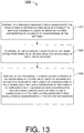
- FIG. 13 illustrates an example process 1300 in accordance with an implementation of the present disclosure.
- Process 1300 may represent an aspect of implementing the proposed concepts and schemes such as those described with respect to some or all of FIG. 1 - FIG. 11 . More specifically, process 1300 may represent an aspect of the proposed concepts and schemes pertaining to reconfigurable RF front end and antenna arrays for radar mode switching.
- Process 1300 may include one or more operations, actions, or functions as illustrated by one or more of blocks 1310, 1320 and 1330. Although illustrated as discrete blocks, various blocks of process 1300 may be divided into additional blocks, combined into fewer blocks, or eliminated, depending on the desired implementation. Moreover, the blocks/sub-blocks of process 1300 may be executed in the order shown in FIG.
- Process 1300 may be implemented by or in apparatus 900A, apparatus 900B and automobile 1000 as well as any variations thereof.
- process 1300 may be implemented by or in apparatus 900A and/or apparatus 900B. Solely for illustrative purposes and without limiting the scope, process 1300 is described below in the context of apparatus 900A/900B implemented as radar system 100 in automobile 1000.
- Process 1300 may begin at block 1310.
- process 1300 may involve processor 910 controlling radar system 100 to operate in a first mode of a plurality of modes by utilizing a plurality of antennas (e.g., antennas 110(1) - 110(4), 120(1) - 120(3), 130(1) - 130(4) and 140) in a first configuration of a plurality of configurations of the antennas.
- Process 1300 may proceed from 1310 to 1320.
- process 1300 may involve processor 910 determining a need to switch radar system 100 from operating in the first mode to a second mode of the plurality of modes. Process 1300 may proceed from 1320 to 1330.
- process 1300 may involve processor 910 controlling radar system 100 to operate in the second mode by utilizing the plurality of antennas in a second configuration of the plurality of configurations of the antennas.
- Each configuration of the plurality of configurations of the antennas may result in respective antenna characteristics such that first antenna characteristics of the first configuration differ from second antenna characteristics of the second configuration.
- the first antenna characteristics of the first configuration may differ from the second antenna characteristics of the second configuration in terms of an antenna gain, a field of view, or both.
- process 1300 may involve processor 910 performing a number of operations. For instance, process 1300 may involve processor 910 activating a first number of transmitters to transmit radar signals through a first subset of one or more antennas of the plurality of antennas having the first number of antennas. Additionally, process 1300 may involve processor 910 activating a second number of receivers to receive reflected radar signals through a second subset of one or more antennas of the plurality of antennas having the second number of antennas.
- process 1300 may involve processor 910 performing a number of operations. For instance, process 1300 may involve processor 910 activating a third number of transmitters to transmit the radar signals through a third subset of one or more antennas of the plurality of antennas having the third number of antennas. Moreover, process 1300 may involve processor 910 activating a fourth number of receivers to receive the reflected radar signals through a fourth subset of one or more antennas of the plurality of antennas having the fourth number of antennas.
- process 1300 may involve processor 910 performing additional operations. For instance, process 1300 may involve processor 910 detecting a fault in at least one of the antennas in the second configuration utilized for radar operations. Furthermore, process 1300 may involve processor 910 controlling radar system 100 to operate in the second mode by utilizing the plurality of antennas in a third configuration of the plurality of configurations of the antennas. In such cases, third antenna characteristics of the third configuration may approximate (e.g., substantially equal to) the second antenna characteristics of the second configuration.
- any two components so associated can also be viewed as being “operably connected”, or “operably coupled”, to each other to achieve the desired functionality, and any two components capable of being so associated can also be viewed as being “operably couplable”, to each other to achieve the desired functionality.
- operably couplable include but are not limited to physically mateable and/or physically interacting components and/or wirelessly interactable and/or wirelessly interacting components and/or logically interacting and/or logically interactable components.
Landscapes
- Engineering & Computer Science (AREA)
- Radar, Positioning & Navigation (AREA)
- Remote Sensing (AREA)
- Physics & Mathematics (AREA)
- Computer Networks & Wireless Communication (AREA)
- General Physics & Mathematics (AREA)
- Electromagnetism (AREA)
- Radar Systems Or Details Thereof (AREA)
- Variable-Direction Aerials And Aerial Arrays (AREA)
Applications Claiming Priority (2)
| Application Number | Priority Date | Filing Date | Title |
|---|---|---|---|
| US201662349682P | 2016-06-14 | 2016-06-14 | |
| US15/620,854 US11835645B2 (en) | 2016-06-14 | 2017-06-13 | Reconfigurable RF front end and antenna arrays for radar mode switching |
Publications (2)
| Publication Number | Publication Date |
|---|---|
| EP3267221A2 true EP3267221A2 (de) | 2018-01-10 |
| EP3267221A3 EP3267221A3 (de) | 2018-03-28 |
Family
ID=59896946
Family Applications (1)
| Application Number | Title | Priority Date | Filing Date |
|---|---|---|---|
| EP17176118.2A Ceased EP3267221A3 (de) | 2016-06-14 | 2017-06-14 | Rekonfigurierbare hf-front-end und gruppenantennen zur radarbetriebsartumschaltung |
Country Status (4)
| Country | Link |
|---|---|
| US (1) | US11835645B2 (de) |
| EP (1) | EP3267221A3 (de) |
| CN (1) | CN109085537B (de) |
| TW (1) | TWI650903B (de) |
Families Citing this family (24)
| Publication number | Priority date | Publication date | Assignee | Title |
|---|---|---|---|---|
| US10401475B2 (en) * | 2016-12-06 | 2019-09-03 | GM Global Technology Operations LLC | Multiple modulation element radar waveform generation |
| KR102132774B1 (ko) * | 2018-01-10 | 2020-07-21 | 주식회사 만도 | 레이더 제어 장치 및 그 방법 |
| CN110391506B (zh) * | 2018-04-18 | 2021-06-01 | 上海华为技术有限公司 | 一种天线系统、馈电网络重构方法及装置 |
| JP6640269B2 (ja) * | 2018-04-19 | 2020-02-05 | 京セラ株式会社 | 電子機器、電子機器の制御方法、及び電子機器の制御プログラム |
| CN110418310B (zh) * | 2018-04-28 | 2021-03-30 | 华为技术有限公司 | 车辆雷达通信一体化的实现方法、相关设备及系统 |
| US20190377814A1 (en) * | 2018-06-11 | 2019-12-12 | Augmented Radar Imaging Inc. | Annotated dataset based on different sensor techniques |
| US10705208B2 (en) | 2018-06-11 | 2020-07-07 | Augmented Radar Imaging, Inc. | Vehicle location determination using synthetic aperture radar |
| US10647328B2 (en) | 2018-06-11 | 2020-05-12 | Augmented Radar Imaging, Inc. | Dual-measurement data structure for autonomous vehicles |
| WO2020067939A1 (en) * | 2018-09-26 | 2020-04-02 | Saab Ab | A vehicle radar system comprising an auxiliary power source |
| US11921233B2 (en) * | 2018-10-02 | 2024-03-05 | Metawave Corporation | Adaptive radar for near-far target identification |
| KR102276975B1 (ko) * | 2018-10-25 | 2021-07-13 | 주식회사 비트센싱 | 레이더 장치 및 레이더 장치에 이용되는 안테나 장치 |
| EP3825718A4 (de) * | 2018-10-25 | 2022-04-13 | Bitsensing Inc. | Radargerät und antennenvorrichtung für radarvorrichtung |
| CN111505641B (zh) | 2019-01-30 | 2023-01-13 | 华为技术有限公司 | 无线电信号发送方法和装置 |
| CN111624603B (zh) * | 2019-02-28 | 2022-12-30 | 华为技术有限公司 | 一种雷达测量方法及装置 |
| CN115079095A (zh) * | 2019-08-19 | 2022-09-20 | 华为技术有限公司 | 信号传输方法及装置、信号处理方法及装置以及雷达系统 |
| US11714183B2 (en) * | 2019-09-03 | 2023-08-01 | Nxp B.V. | Impulse radar using variable pulse repetition frequency |
| US11444377B2 (en) * | 2019-10-03 | 2022-09-13 | Aptiv Technologies Limited | Radiation pattern reconfigurable antenna |
| TWI704535B (zh) | 2019-11-11 | 2020-09-11 | 財團法人工業技術研究院 | 天線陣列及包含此天線陣列的汽車防撞雷達 |
| KR102288673B1 (ko) * | 2020-12-28 | 2021-08-12 | 주식회사 비트센싱 | 수평 간격 및 수직 간격으로 배치되는 복수의 안테나를 포함하는 레이더 장치 |
| CN113013583B (zh) * | 2021-01-29 | 2023-08-18 | 中国电子科技集团公司第三十八研究所 | 毫米波雷达封装模组 |
| WO2022203815A1 (en) * | 2021-03-23 | 2022-09-29 | Metawave Corporation | Parallel processing in a radar system |
| CN113933830A (zh) * | 2021-09-28 | 2022-01-14 | 中国人民解放军海军航空大学 | 多站双模pcl/有源雷达组网系统及定位方法 |
| DE102023209255A1 (de) * | 2023-09-22 | 2025-03-27 | Robert Bosch Gesellschaft mit beschränkter Haftung | Radarvorrichtung und Verfahren zum Auswerten von Radarmesssignalen einer Radarvorrichtung |
| WO2025079034A2 (en) * | 2023-10-13 | 2025-04-17 | Mobileye Vision Technologies Ltd. | Dual function vehicular radar, and applications thereof |
Citations (1)
| Publication number | Priority date | Publication date | Assignee | Title |
|---|---|---|---|---|
| US6043790A (en) * | 1997-03-24 | 2000-03-28 | Telefonaktiebolaget Lm Ericsson | Integrated transmit/receive antenna with arbitrary utilization of the antenna aperture |
Family Cites Families (17)
| Publication number | Priority date | Publication date | Assignee | Title |
|---|---|---|---|---|
| JP3430019B2 (ja) | 1998-06-22 | 2003-07-28 | 三菱電機株式会社 | マイクロ波送信装置 |
| DE10348226A1 (de) | 2003-10-10 | 2005-05-04 | Valeo Schalter & Sensoren Gmbh | Radarsystem mit umschaltbarer Winkelauflösung |
| CA2466087A1 (en) | 2001-12-14 | 2003-06-26 | Luis M. Viana | Back-up aid indicator |
| US6750810B2 (en) | 2001-12-18 | 2004-06-15 | Hitachi, Ltd. | Monopulse radar system |
| EP2197128B1 (de) * | 2003-04-25 | 2016-05-11 | AT&T Mobility II LLC | Systeme und Verfahren zum Einsatz von voll-redundantem Frequenzsprungverfahren mit Mehrträger-Leistungsverstärkung und Kombinationssystemen innerhalb einer Basisstation |
| DE102004059915A1 (de) * | 2004-12-13 | 2006-06-14 | Robert Bosch Gmbh | Radarsystem |
| US7528613B1 (en) * | 2006-06-30 | 2009-05-05 | Rockwell Collins, Inc. | Apparatus and method for steering RF scans provided by an aircraft radar antenna |
| IL182936A (en) | 2006-09-06 | 2012-03-29 | Alberto Milano | System and method of communication using a phase shift controlled antenna array |
| WO2010122860A1 (ja) | 2009-04-23 | 2010-10-28 | 三菱電機株式会社 | レーダ装置およびアンテナ装置 |
| WO2011106881A1 (en) | 2010-03-05 | 2011-09-09 | University Of Windsor | Radar system and method of manufacturing same |
| US8902103B2 (en) | 2011-03-16 | 2014-12-02 | Electronics And Telecommunications Research Institute | Radar apparatus supporting short and long range radar operation |
| EP2864632B1 (de) * | 2012-06-26 | 2016-04-27 | Vestas Wind Systems A/S | Windturbinenschaufel-vibrationsdetektion und radarkalibrierung |
| TW201425975A (zh) | 2012-12-19 | 2014-07-01 | Wistron Neweb Corp | 雷達系統及雷達系統控制方法 |
| CN104122556B (zh) | 2013-04-24 | 2017-08-15 | 启碁科技股份有限公司 | 用于车用雷达系统的雷达装置 |
| KR20150017976A (ko) | 2013-08-08 | 2015-02-23 | 주식회사 만도 | 차량용 레이더 및 그 운용 방법 |
| US9819098B2 (en) | 2013-09-11 | 2017-11-14 | International Business Machines Corporation | Antenna-in-package structures with broadside and end-fire radiations |
| EP3091272B1 (de) * | 2015-05-05 | 2018-01-03 | Sick Ag | Lichtgitter |
-
2017
- 2017-06-13 US US15/620,854 patent/US11835645B2/en active Active
- 2017-06-14 TW TW106119767A patent/TWI650903B/zh not_active IP Right Cessation
- 2017-06-14 EP EP17176118.2A patent/EP3267221A3/de not_active Ceased
-
2018
- 2018-06-08 CN CN201810588516.0A patent/CN109085537B/zh active Active
Patent Citations (1)
| Publication number | Priority date | Publication date | Assignee | Title |
|---|---|---|---|---|
| US6043790A (en) * | 1997-03-24 | 2000-03-28 | Telefonaktiebolaget Lm Ericsson | Integrated transmit/receive antenna with arbitrary utilization of the antenna aperture |
Also Published As
| Publication number | Publication date |
|---|---|
| TWI650903B (zh) | 2019-02-11 |
| US11835645B2 (en) | 2023-12-05 |
| EP3267221A3 (de) | 2018-03-28 |
| CN109085537A (zh) | 2018-12-25 |
| US20170276770A1 (en) | 2017-09-28 |
| TW201803207A (zh) | 2018-01-16 |
| CN109085537B (zh) | 2024-03-29 |
Similar Documents
| Publication | Publication Date | Title |
|---|---|---|
| US11835645B2 (en) | Reconfigurable RF front end and antenna arrays for radar mode switching | |
| CN108120958B (zh) | 具有多输入多输出天线的雷达装置 | |
| US8620248B2 (en) | Multichannel receiver system and method for multichannel receiver monitoring | |
| CN111245479B (zh) | 被配置为执行波束扫描操作的无线通信设备及其操作方法 | |
| US11705739B2 (en) | Communication system | |
| US20110163906A1 (en) | Radar apparatus, antenna apparatus, and data acquisition method | |
| US11349208B2 (en) | Antenna apparatus with switches for antenna array calibration | |
| EP4082079B1 (de) | Phasengesteuertes modul | |
| CN109217908B (zh) | 电子扫描阵列 | |
| WO2008066325A1 (en) | Method and apparatus for signal detection in radio frequency identification system | |
| US12136987B2 (en) | Electronic device for beam search, and method therefor | |
| CN213750323U (zh) | 雷达装置及可移动平台 | |
| EP4239891A1 (de) | Elektronische vorrichtung zum betrieb eines übertragungswegs und steuerungsverfahren dafür | |
| JP2024041586A (ja) | レーダ装置 | |
| EP3809604B1 (de) | Verfahren zum betrieb einer vorrichtung zum senden und/oder empfangen von hochfrequenzsignalen | |
| KR102706293B1 (ko) | 안테나 장치 및 이를 포함하는 레이더 장치 | |
| US11747437B2 (en) | Device and method for transmitting a radar signal | |
| US12413317B2 (en) | Apparatus and method for error correction in wireless communication system | |
| US20230198638A1 (en) | Antenna module for generating self testing signal and electronic device using it | |
| KR100753367B1 (ko) | Autonomous GPS기능이 내장된 내장형 안테나및 상기 안테나를 구현하는 방법 | |
| De Long | An integrated approach to topside design | |
| CN112816984A (zh) | 一种雷达电路、雷达和设备 | |
| CN116299398B (zh) | 一种应用于飞行器的目标测距方法、装置及电子设备 | |
| US11206067B2 (en) | Antenna system, control method of antenna system, storage medium, wireless communication apparatus and system | |
| WO2023048613A1 (en) | An electronic device, a method, a computer program product, and a single-chip radio |
Legal Events
| Date | Code | Title | Description |
|---|---|---|---|
| PUAI | Public reference made under article 153(3) epc to a published international application that has entered the european phase |
Free format text: ORIGINAL CODE: 0009012 |
|
| STAA | Information on the status of an ep patent application or granted ep patent |
Free format text: STATUS: THE APPLICATION HAS BEEN PUBLISHED |
|
| AK | Designated contracting states |
Kind code of ref document: A2 Designated state(s): AL AT BE BG CH CY CZ DE DK EE ES FI FR GB GR HR HU IE IS IT LI LT LU LV MC MK MT NL NO PL PT RO RS SE SI SK SM TR |
|
| AX | Request for extension of the european patent |
Extension state: BA ME |
|
| PUAL | Search report despatched |
Free format text: ORIGINAL CODE: 0009013 |
|
| AK | Designated contracting states |
Kind code of ref document: A3 Designated state(s): AL AT BE BG CH CY CZ DE DK EE ES FI FR GB GR HR HU IE IS IT LI LT LU LV MC MK MT NL NO PL PT RO RS SE SI SK SM TR |
|
| AX | Request for extension of the european patent |
Extension state: BA ME |
|
| RIC1 | Information provided on ipc code assigned before grant |
Ipc: G01S 7/02 20060101ALN20180220BHEP Ipc: H01Q 3/24 20060101ALI20180220BHEP Ipc: H01Q 21/00 20060101ALI20180220BHEP Ipc: H01Q 25/00 20060101ALI20180220BHEP Ipc: G01S 7/40 20060101ALN20180220BHEP Ipc: G01S 13/93 20060101AFI20180220BHEP Ipc: G01S 13/02 20060101ALN20180220BHEP Ipc: H01Q 21/06 20060101ALI20180220BHEP Ipc: H01Q 1/32 20060101ALI20180220BHEP |
|
| STAA | Information on the status of an ep patent application or granted ep patent |
Free format text: STATUS: REQUEST FOR EXAMINATION WAS MADE |
|
| 17P | Request for examination filed |
Effective date: 20180921 |
|
| RBV | Designated contracting states (corrected) |
Designated state(s): AL AT BE BG CH CY CZ DE DK EE ES FI FR GB GR HR HU IE IS IT LI LT LU LV MC MK MT NL NO PL PT RO RS SE SI SK SM TR |
|
| STAA | Information on the status of an ep patent application or granted ep patent |
Free format text: STATUS: EXAMINATION IS IN PROGRESS |
|
| 17Q | First examination report despatched |
Effective date: 20200507 |
|
| STAA | Information on the status of an ep patent application or granted ep patent |
Free format text: STATUS: THE APPLICATION HAS BEEN REFUSED |
|
| 18R | Application refused |
Effective date: 20220913 |