EP3266948B1 - Vorrichtung und verfahren zum aufhängen einer zwischendecke sowie eine zwischendecke - Google Patents
Vorrichtung und verfahren zum aufhängen einer zwischendecke sowie eine zwischendecke Download PDFInfo
- Publication number
- EP3266948B1 EP3266948B1 EP16177965.7A EP16177965A EP3266948B1 EP 3266948 B1 EP3266948 B1 EP 3266948B1 EP 16177965 A EP16177965 A EP 16177965A EP 3266948 B1 EP3266948 B1 EP 3266948B1
- Authority
- EP
- European Patent Office
- Prior art keywords
- adhesive
- housing
- housing cavity
- suspension member
- ceiling
- Prior art date
- Legal status (The legal status is an assumption and is not a legal conclusion. Google has not performed a legal analysis and makes no representation as to the accuracy of the status listed.)
- Active
Links
Images




Classifications
-
- E—FIXED CONSTRUCTIONS
- E04—BUILDING
- E04B—GENERAL BUILDING CONSTRUCTIONS; WALLS, e.g. PARTITIONS; ROOFS; FLOORS; CEILINGS; INSULATION OR OTHER PROTECTION OF BUILDINGS
- E04B9/00—Ceilings; Construction of ceilings, e.g. false ceilings; Ceiling construction with regard to insulation
- E04B9/18—Means for suspending the supporting construction
-
- F—MECHANICAL ENGINEERING; LIGHTING; HEATING; WEAPONS; BLASTING
- F16—ENGINEERING ELEMENTS AND UNITS; GENERAL MEASURES FOR PRODUCING AND MAINTAINING EFFECTIVE FUNCTIONING OF MACHINES OR INSTALLATIONS; THERMAL INSULATION IN GENERAL
- F16B—DEVICES FOR FASTENING OR SECURING CONSTRUCTIONAL ELEMENTS OR MACHINE PARTS TOGETHER, e.g. NAILS, BOLTS, CIRCLIPS, CLAMPS, CLIPS OR WEDGES; JOINTS OR JOINTING
- F16B45/00—Hooks; Eyes
- F16B45/005—Hooks; Eyes characterised by the material
-
- F—MECHANICAL ENGINEERING; LIGHTING; HEATING; WEAPONS; BLASTING
- F16—ENGINEERING ELEMENTS AND UNITS; GENERAL MEASURES FOR PRODUCING AND MAINTAINING EFFECTIVE FUNCTIONING OF MACHINES OR INSTALLATIONS; THERMAL INSULATION IN GENERAL
- F16B—DEVICES FOR FASTENING OR SECURING CONSTRUCTIONAL ELEMENTS OR MACHINE PARTS TOGETHER, e.g. NAILS, BOLTS, CIRCLIPS, CLAMPS, CLIPS OR WEDGES; JOINTS OR JOINTING
- F16B47/00—Suction cups for attaching purposes; Equivalent means using adhesives
- F16B47/003—Suction cups for attaching purposes; Equivalent means using adhesives using adhesives for attaching purposes
Definitions
- the present invention relates to suspended ceilings and more specifically to a device for suspension of a suspended ceiling, a suspended ceiling system comprising such a device and a method for suspension of a suspended ceiling in a structural ceiling.
- concrete When constructing buildings or similar, concrete is often used as it is a cost effective rigid material having a long service life.
- the foundation, the walls, the floor structures and the roof structures are commonly formed by reinforced concrete.
- suspended ceilings When using concrete slabs, it is common to use so called suspended ceilings or false ceilings.
- the suspended ceilings are then provided below the structural ceiling formed by the concrete slabs themselves.
- the suspended ceilings are commonly made up of a number of tiles which are suspended from the concrete slabs forming the structural ceiling.
- hooks, wires, rods or similar are then provided in the drilled holes and the tiles are in turn suspended from the hooks, wires, rods or similar.
- the suspended ceiling may be formed by ceiling tiles supported by a grid of profiles which in turn is suspended in the structural ceiling by means of the hooks, wires, rods or similar mentioned above.
- the suspended ceiling may be formed by individually suspended and free hanging ceiling tiles using some of said hooks, wires, rods or similar.
- the drilling of holes in the structural ceiling for suspension of ceiling tiles is for natural reasons time consuming.
- the time consuming work implies high costs due to e.g. personnel expenses.
- the working environment might be a health hazard to the person drilling the holes due to the exposure to vibrations, noise and concrete dust.
- the noise may also constitute an inconvenience for the tenants in the building since the noise easily propagates through the building.
- the slabs comprise reinforcement bars which have to be avoided during drilling.
- TABS Thermally Active Building Structures
- TABS are becoming increasingly popular, due to its ability to cool or heat the indoor environment of the building.
- TABS are used to control the indoor environment of a concrete building, by cooling or heating the concrete slabs of the building.
- the concrete slabs are provided with channels in form of pipes, ducts or similar. Water having a controlled temperature is then circulated in the channels in order to heat or cool the beams, which in turn heats or cools the building.
- the channels provided in the slabs are situated close to the lower surface of the slab, i.e. close to the structural ceiling of the building.
- the reason for the channels being provided close to the surface is that an improved efficiency is achieved by this arrangement.
- the channels are typically provided only a few centimeters below the concrete surface of the slabs of the building.
- the drilling locations might be determined if the personnel drilling the holes are aware of the locations of the channels within the slabs.
- the process of determining the drilling locations is time consuming and undesired.
- a hanger fixture for cementitious connection to a surface.
- the hanger fixture comprises a perforated plate supporting a threaded portion which in turn threadingly engages a hanger, such as a hook.
- the base plate is attached to the surface by means of a cementitious adhesive.
- WO2015/015224A1 discloses a fixing member for adhering in use to a substrate part to fix a fixed part to the substrate part.
- the fixing member comprises a base and a fixing formation on a top side of the base.
- the base has a concavity in its underside for accommodating adhesive for adhering it to the substrate part.
- WO2014/207145A1 discloses a suspension element comprising an elongated support element and an attachment part fitted on a first end of the support element.
- the attachment part is provided with a number of recesses for accommodating adhesive.
- the object of the present invention is to provide an improved device and method for suspension of suspended ceilings.
- a device having the features defined in claim 1 a suspended ceiling system having the features defined in claim 10 and a method having the features defined in claim 12 are provided according to the present invention. Preferred embodiments of the device and method will be evident from the dependent claims.
- a device for suspension of a suspended ceiling comprising an elongated suspension member having a first end and an opposing second end, an anchoring head being arranged at the first end, a housing having an open top side and an opposed, closed bottom side, the housing defining a housing cavity adapted to be filled with an adhesive, and a suspension member holder being hollow and arranged in the housing cavity and forming an extension of a passage which is provided extending through the closed bottom side of the housing, wherein the elongated suspension member in a assembled state of the device extends through the passage with the first end positioned inside the housing cavity and the second end positioned outside the housing cavity.
- the suspension member holder positions, in the assembled state of the device, the first end and the thereto arranged anchoring head of the suspension member inside the housing cavity at a distance H1 from the closed bottom side.
- an elongated suspension member may be any type of elongated member suitable for suspending a suspended ceiling.
- an elongated suspension member may comprise a hook, wire, rod or similar.
- suspended ceiling may be any type of ceiling arranged below a structural ceiling.
- the suspended ceiling may be formed by ceiling tiles supported by a grid of profiles which in turn is suspended in the structural ceiling.
- the suspended ceiling may be formed by individually suspended and free hanging ceiling tiles.
- the housing having a housing cavity adapted to be filled with the adhesive provides a mould which is easy to use when installing the inventive device.
- the suspension member holder forms a spacer for positioning the anchoring head at a distance H1 from the bottom side.
- the suspension member holder may be formed as a separate part.
- the suspension member holder may be integrally formed with the closed bottom side of the housing or may be integrally formed with the anchoring head.
- a suspension member holder arranged to position the first end and associated anchoring head at a distance H1 from the closed bottom side of the housing ensures that the anchoring head efficiently may transfer a load form the suspension member to the structural ceiling in the installed state of the inventive device.
- the inventive device may filled with an adhesive in the form of a cement composition and the device may then be designed with such a distance H1 between the anchoring head arranged at the first end of the suspension member holder and the closed bottom side of the housing resulting in a cone failure of the adhesive in the installed state of the device corresponding to a desired maximum load bearing capacity of the device.
- the suspension member holder may be arranged to hold the suspension member such that the anchoring head becomes embedded when the housing cavity is filled with the adhesive.
- the anchoring head may have a head width W1 which is greater than a holder width W2 of the suspension member holder.
- an overhang or undercut is provided ensuring that the anchoring head is properly embedded when the housing cavity is filled with an adhesive.
- the adhesive is a cement composition, this may result in a controlled cone failure when the maximum load bearing capacity of the device is reached.
- the distance H1 may be in the range of 5-50 mm and more preferably in the range of 8-15 mm.
- the housing has a height H2 and the difference between the height H2 and the distance H1 may be in the range of 0-10 mm and more preferably in the range of 2-5 mm. If the difference between the height H2 and the distance H1 is greater than zero, a cavity space is formed above the anchoring head, which cavity space is filled when the cavity is filled with the adhesive. Hereby an increasedadhesive strength may be obtain in the load bearing interface between the adhesive and the structural ceiling in the installed state of the device.
- the housing may be provided with exterior mounting means arranged for cooperation with a mounting tool.
- a mounting tool arranged for cooperation with a mounting tool.
- the device may have housing with a cylindrical shape.
- the housing may be made of a polymer or metal material.
- a fully cured adhesive may be arranged in the housing cavity, wherein a head space is provided extending between an upper surface of the fully cured adhesive and the open top side of the housing.
- a suspended ceiling system comprising a suspended ceiling suspended in a structural ceiling of a building by means of a device according to the above.
- the housing cavity of the housing is filled with an adhesive embedding the anchoring head is positioned inside the housing cavity, and the adhesive is bonded to the structural ceiling at the open top side of the housing.
- a load applied to the second end of the suspension element is transferred to the structural ceiling via the anchoring head embedded in the adhesive.
- the adhesive may be a cement composition.
- a method for suspension of a suspended ceiling to a structural ceiling of a building comprising providing a device for suspension of a suspended ceiling, the device comprising an elongated suspension member having a first end and an opposing second end, an anchoring head being arranged at the first end, a housing having an open top side and an opposed, closed bottom side, the housing defining a housing cavity adapted to be filled with an adhesive, and a suspension member holder being hollow and arranged in the housing cavity and forming an extension of a passage which is provided extending through the closed bottom side of the housing, arranging the elongated suspension member such that it extends through the passage of the suspension member holder with the first end and the thereto arranged anchoring head positioned by the suspension member holed inside the housing cavity at a distance H1 from the closed bottom side and the second end positioned outside the housing cavity, filling the housing cavity with an adhesive, and pressing the device against the structural ceiling with the open top end of the housing facing the structural ceiling such that
- the step of filling the housing cavity may comprise overfilling the housing cavity with the adhesive such that the adhesive piles up through the open top side of the housing.
- the housing cavity may be completely filled during installation of the device whereas surplus adhesive may be pressed away and be dispensed with.
- it may further comprise matching the properties of the adhesive with corresponding properties of the structural ceiling, the properties at least including crimping property, compression strength, thermal expansion or moist expansion.
- matching the properties it is possible to increase the adhesive strength between the adhesive and the structural ceiling, i.e. the adhesive strength of the load bearing interface, and also to maximize the life span of the load bearing interface.
- the adhesive may be a cement composition.
- Calcium aluminate cement may be included in the cement composition.
- the adhesive used is selected from the group of adhesives having a tack sufficient for the device to adhere to the structural ceiling once it has been pressed against the same and a basic curing time in the range of 15-60 minutes.
- basic curing time is meant the time required for the adhesive to cure sufficiently for the device to be able to bear a desired load.
- the total curing time i.e. when the curing has been fully completed, may be longer, for instance 25-30 days.
- the step of filling the housing cavity with an adhesive may comprise a sub step of partly filling the hosing cavity with a first adhesive such that an unfilled head space is formed in the housing cavity and a second sub step of final filling of the housing cavity with a second adhesive, wherein the sub step of final filling of the housing cavity is performed after the first adhesive has cured.
- the first adhesive may be added in such amount that the anchoring head becomes fully embedded in the first adhesive.
- the first adhesive and the second adhesive may be of the same type or of different types.
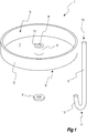
- Fig. 1 discloses different components of an embodiment of a device 1 for suspension of a suspended ceiling according to the invention.
- the device 1 is shown in a disassembled state and comprises a housing 2, an elongated suspension member 3 and an anchoring head 4.
- the housing 2 has an open top side 5 and a closed bottom side 6; and defines a housing cavity 7 adapted to be filled with an adhesive.
- the housing 2 has a circular shape, but it is understood that other shapes are possible.
- the housing may be made of any suitable material, such as plastic or metal.
- the housing 2 is provided with a passage 9 extending through the closed bottom side 6 of the housing 2.
- the housing 2 further comprises a suspension member holder 8 which is arranged in the housing cavity 7.
- the suspension member holder is hollow and thus forms an extension of the passage 9 extending through the closed bottom side 6 of the housing 2.
- the suspension member holder 8 is arranged in a housing wall section included in the bottom side 6 of the housing 2. More specifically, the suspension member holder 8 is formed by a protrusion extending into the housing cavity 7 from the housing wall section, wherein the passage 9 is formed by a through hole extending through the protrusion in a direction perpendicular to a plane defined by the extension of the bottom side 6 of the housing 2.
- the suspension member holder may be formed as a separate piece or may be formed integrally with the anchoring head.
- the elongated suspension member 3 has a first end 10 and an, opposing second end 11.
- the anchoring head 4 is arranged at the first end 10 and may for instance be constituted by a nut arranged to be screwed on to a thread provided at the first end of the suspension member.
- the second end 11 of the suspension member 3 may be provided with a suspension arrangement 12, such as a hook, as disclosed in the shown embodiment, or an external thread..
- the suspension member is formed by a rod provided with a hook. It is understood that the suspension member may be designed differently. For instance, the length of the suspension member might be adjustable and may for this reason comprise two mutually displaceable rods. Alternatively, the suspension member may be formed by a wire or a string.
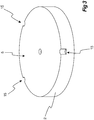
- the inventive device 1 is shown in an assembled state.
- the first end 10 has been inserted into the passage 9 and arranged in the housing cavity 7, and the anchoring head 4 has been arranged at and attached to the first end 10.
- the suspension member 3 extends through the passage 9 with the first end 10, and hence also the anchoring head 4 connected thereto, positioned inside the housing cavity 7 and the second end 11 positioned outside the housing cavity 7.
- the suspension member holder 8 positions the first end 10 and the thereto attached anchoring head 4 of the suspension member 3 at a distance H1 from the closed bottom side 6. In the shown embodiment this is accomplished by the protrusion forming the suspension member holder 8, the protrusion having an upper bearing surface 13 (indicated in Fig. 1 ) supporting the anchoring head 4 in the assembled state of the device 1.
- the anchoring head 4 has a head width W1 which is greater than a holder width W2 of the suspension member holder 8. Since both the anchoring head 4 and the suspension member holder 8 are circular in the shown embodiment, the head width W1 and the holder width W2 correspond to the associated diameter.
- the difference in width between the anchoring head 4 and the suspension member holder 8 ensures that the anchoring head becomes embedded with an overhang 14 or an undercut when the housing cavity is filled with an adhesive, which will be described more in detail below.
- the housing 2 may be provided with exterior mounting means 15 arranged for cooperation with a mounting tool.
- the mounting means 15 is formed by recesses arranged about the periphery of the bottom side 6 of the housing 2.
- the mounting tool (not shown) may in this case be provided with corresponding projections to be received by the recesses in order to enable rotational movement of the housing 2 during installation or mounting of the inventive device 1 on a structural ceiling.
- the device 1 is used in an inventive method for suspension of a suspended ceiling.
- the method comprises installation or mounting of the device 1 on the structural ceiling and an embodiment of the method will now be described more in detail with reference to Figs. 4a-4e .
- Fig. 4a schematically illustrates an embodiment of the inventive device 1 in an assembled state.
- the elongated suspension member 3 extends through the passage of the suspension member holder of the housing 2 such that the first end and the anchoring head attached thereto is positioned inside the housing cavity at a distance from the closed bottom side 6 and the second end 11 is positioned outside the housing cavity 7.
- the second end 11 is provided with a suspension arrangement 12 in the form of a hook.
- the housing cavity has been filled with an adhesive 16, such as a cement composition.
- the housing cavity is overfilled with the adhesive 16, such that the adhesive 16 plies up through the open top side 5 of the housing 2.
- a mounting tool 17 is moved to towards the inventive device 1 in the direction indicated by arrow P1.
- the mounting tool 17 comprises an upper section 18 provided with a central opening 19 allowing the upper section 18 to be passed over the second end 11 of the suspension member 3.
- the upper section 18 is connected to a handle 20 via two arms 21.
- the upper section 18 is passed over the second end 11 of the suspension member 3 in order to be brought to the closed bottom side 6 of the housing 2 such that two projections 22 arranged on top of the upper section 17 are received in corresponding recesses in the closed bottom side 6 of the housing 2.
- the handle may be of sufficient length, such that a person using the mounting tool may reach the structural ceiling and mount the device standing on the floor.
- the length of the handle may be adjustable and may for this reason be telescopic.
- the inventive device 1 has been moved in the P1 direction towards a structural ceiling 23 by means of the mounting tool 17.
- the open top side of the housing 2 is facing the structural ceiling 23, and by pressing the device 1 against the ceiling 23, the adhesive comes into contact with the structural ceiling 23.
- the housing 2 will act as a mould for the adhesive while the device 1 is pressed against the structural ceiling 23.
- the projections of the upper section 18 of the mounting tool 17 received in the recesses of the housing 2 enables the device 1 to be turned or rotated in the direction indicated by arrow P2 by means of the mounting tool 17 while simultaneous pressing the device 1 against the ceiling 23. Herby it is ensured that the adhesive fills up the housing cavity while surplus adhesive material 24 may be pressed out. The surplus adhesive material 24 may subsequently be removed.
- the part of the structural ceiling 23 against which the inventive device 1 is pressed may be pre-treated.
- the pre-treatment may comprise priming, brushing and/or washing.
- it may be sufficient to pre-treat the part of the structural ceiling by brushing with a wire brush in order to rug the surface.
- the adhesive 16 may bond and form a load bearing interface indicated at 25.
- Fig. 4e the mounting tool 17 is removed in the direction indicated by arrow P3 leaving the inventive device 1 attached to the structural ceiling 23.
- a plurality of devices 1 mounted as described above may then be used for installation of a grid of profiles in which a plurality ceiling tiles subsequently may be placed.
- the devices may be used of installation of free hanging ceiling tiles by means of suitable means such as wires, rods or strings.
- pre-filled devices may be used.
- the filling of the assembled device 1 with an adhesive is performed in a two-step process, wherein the two steps may be separate in time and location.
- the assembled device 1 is partly filled with a first adhesive 16', as illustrated in Fig. 5a .
- the first adhesive 16' may be filled into the housing cavity 7 such that the anchoring head 4 becomes fully embedded in the adhesive 16' while leaving an unfilled head space in the housing cavity 7.
- the head space extends between an upper surface 27 of the first adhesive 16' and the open top side 5 of the housing 2 and may have a height H3 of 2-5 mm.
- the first step may be performed at a production plant in an automated process and the pre-filled device 1 may be vibrated in order to prevent entrapment of air in the adhesive 16' added in the first step.
- the adhesive 16' added in the first step may be allowed to fully cure before a second step of the alternative method is preformed.
- the pre-filled devices 1 may be stored before being subjected to the second step.
- the reminder of the housing cavity 7 is filled with a second adhesive 16", as illustrated in Fig. 5b .
- the second step is performed at the site at which the device 1 is to be used for suspension of a suspended ceiling.
- the second adhesive 16" used in the second step may be added in such amount that it piles up through the open top side 5 of the housing 2.
- the device 1 may then be pressed against a structural ceiling for mounting thereon in a way corresponding to that described above with reference to Figs. 4c-4d .
- the first adhesive 16' and the second adhesive 16" may be of different types. Alternatively, the first adhesive 16' and the second adhesive 16" may be of the same type.
- pre-filled devices means that the amount of second adhesive to be used at the site where the devices are to be mounted or installed may be minimized, which is beneficial in terms of both time and logistics.
- first adhesive added in the first step will after curing impart considerable rigidity to the pre-filled device.
- the rigidity of the pre-filled device may facilitate the mounting of the device when the second adhesive of the second step has been added and when the device subsequently is pressed against the structural ceiling.
- the first adhesive used in the first step of the alternative embodiment of the inventive method disclosed above with reference to Figs. 5a-b may be a conventional adhesive, such as a conventional Portland cement composition.
- the second adhesive used in the second step or, alternatively, the adhesive used for filling of the entire housing cavity either in a single step process or in a two step process may be an adhesive having a tack sufficient to allow removal of the mounting tool once the device has been pressed against the structural ceiling and optionally also to allow application of a minor load, such as connecting a hanger to the second end of the suspension member.
- the adhesive may thus have a tack or stickiness resulting in a load bearing capacity in the range of 0,5-2 kg (i.e. the weight of the device and optionally also of a minor load).
- the hanger Once the adhesive has cured sufficiently, the hanger may in turn be connected to a grid of profiles included in the suspended ceiling intended to be suspended by means of the inventive device.
- the adhesive may further have a basic curing time allowing application of a desired load to the suspension member within certain time frame.
- the desired load may correspond to a proportional share of the weight of the grid of profils multiplied by a saefty factor F which may be in the range of 2-3.
- the basic curing time may be in the range 15-60 minutes.
- the desired load may be in the range of 5-10 kg.
- basic curing time is thus meant the time required for the adhesive to cure sufficiently for the device to be able to bear the desired load.
- the time required for the adhesive to fully cure may be longer, for instance 25-30 days.
- the load bearing capacity of the of the installed device once the adhesive added at the site has fully cured may be at least 70 kg.
- the adhesive may be a cement composition.
- the cement composition may include calcium aluminate cement.
- a water-cement ratio (w/c) of about 0,4 may be used in order to achieve required non-aging properties.
- the adhesive used together with the inventive device may have properties matched with corresponding properties of the structural ceiling.
- the matched properties may comprise at least one of crimping property, compression strength, thermal expansion or moist expansion (i.e. expansion caused by exposure to moisture).
- the adhesive added in the second step may also be matched with the adhesive added in the first step.
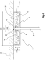
- FIG. 6 A cross section of an embodiment of the inventive device 1 attached to a structural ceiling 23 is shown in Fig. 6 . As evident from the figure, the housing cavity 7 is filled with the adhesive 16 thereby embedding the anchoring head 4 of the suspension member 3.
- the anchoring head 4 has a head width W1 which is greater than a holder width W2 of the suspension member holder 8, whereby an overhang 14 or undercut is formed allowing the anchoring head to become properly embedded in the adhesive 16 allowing load transfer from the embedded anchoring head 4 to the structural ceiling 23.
- the upper bearing surface 13 of the protrusion forming the suspension member holder 8 in the shown embodiment is arranged such that the anchoring head 4 is positioned at a distance H1 from the closed bottom side 6 of the housing 2.
- the housing 2 has a housing height H2, and the difference between the housing height H2 and the distance H1 ensures the formation of a cavity space 26 above the anchoring head 4 which is occupied by the adhesive 16.
- the load will be transferred to the structural ceiling 23 via the anchoring head 4. More specifically, the load will be transferred from the anchoring head 4 to the adhesive 16 and further to the structural ceiling 23 via the load bearing interface 25 formed by the adhesive 16 bonding to the structural ceiling 23.
- the cone angle A of the cone failure may be in the range 20-40° for a cement composition comprising calcium aluminate cement.
- the load required for generating a controlled cone failure will be dependent on the cement composition used and also the cone size.
- the cone size is dependent on the cone angle a as well as the cone height, which essentially correspond to the distance H1.
- the housing width W3 should be sufficient for accommodating the cone.
- inventive devices having circular housings were used.
- the housing height H2 and the distance H2 of the housings were 12 and 10 mm, respectively.
- the housing width W3, i.e. the diameter, was 60 mm.
- an adhesive was used in the form of a cement composition according to EN 1504, class R3. The housing cavity was filled with the adhesive in a single step process.
- Controlled cone failures with a cone angle A of about 30° were observed when the applied load amounted to about 1100 N, i.e. well below the failure limit of the load bearing interface between the adhesive and the structural ceiling.
- a suspended ceiling system 100 according to the invention is shown in Fig. 7 , to which reference now is made.
- the suspended ceiling system 100 comprises a grid of profiles 101 supporting a number of ceiling panels 102.
- Hangers 103 are attached to the grid of profiles 101, and each hanger 103 is connected to a device 1 of the type described above for instance with reference to Fig. 2 .
- Each device 1 is in turn attached to a structural ceiling (not shown) by means of the adhesive 16 bonded to the same.
- the hanger 103 is provided with an upper hook 104 connecting to a suspension arrangement 12 in the form of a hook provided at the second end 11 of the suspension member 3 of the device 1.
- the hangers 103 may, as in the shown embodiment, be of the type having an adjustable length.
- the devices 1 are mounted at selected positions on the structural ceiling. These positions may be determined and indicated by using laser measurement equipment.
- a hanger 103 may be connected to the second end 11 of the suspension member 3 since the adhesive 16 used may have a tack or stickiness sufficient for the device immediately after mounting to adhere to the structural ceiling and also to bear a minor load.
- the installation of the grid of profiles 101 may commence. Since the adhesive 16 used may have a basic curing time in the range of 15-60 minutes, this work may commence immediately after the mounting of the devices 1 by using the devices installed first.
- the ceiling panels 102 may be installed in the frames defined by the grid of profiles 101.
Landscapes
- Engineering & Computer Science (AREA)
- General Engineering & Computer Science (AREA)
- Architecture (AREA)
- Mechanical Engineering (AREA)
- Physics & Mathematics (AREA)
- Electromagnetism (AREA)
- Civil Engineering (AREA)
- Structural Engineering (AREA)
- Joining Of Building Structures In Genera (AREA)
Claims (18)
- Vorrichtung zum Abhängen einer abgehängten Decke, umfassendein längliches Abhängungselement (3) mit einem ersten Ende (10) und einem gegenüberliegenden zweiten Ende (11), wobei ein Verankerungskopf (4) an dem ersten Ende (10) angeordnet ist,ein Gehäuse (2) mit einer offenen Oberseite (5) und einer gegenüberliegenden geschlossenen Unterseite (6), wobei das Gehäuse (2) einen Gehäusehohlraum (7) definiert, der ausgelegt ist, um mit einem Klebstoff (16) gefüllt zu werden, undeinen Abhängungselement-Halter (8), der hohl und in dem Gehäusehohlraum (7) angeordnet ist und eine Erstreckung eines Durchgangs (9) bildet, der sich durch die geschlossene Unterseite (6) des Gehäuses (2) erstreckend vorgesehen ist,wobei sich das längliche Abhängungselement (3) in einem zusammengesetzten Zustand der Vorrichtung durch den Durchgang (9) erstreckt, wobei das erste Ende (10) im Inneren des Gehäusehohlraums (7) positioniert ist und das zweite Ende (11) außerhalb des Gehäusehohlraums (7) positioniert ist,dadurch gekennzeichnet, dass der Abhängungselement-Halter (8) in dem zusammengesetzten Zustand der Vorrichtung das erste Ende (10) und den daran angeordneten Verankerungskopf (4) des Abhängungselements (3) im Inneren des Gehäusehohlraums (7) in einem Abstand H1 von der geschlossenen Unterseite (6) positioniert.
- Vorrichtung nach Anspruch 1, wobei der Abhängungselement-Halter (8) angeordnet ist, um das Abhängungselement (3) derart zu halten, dass der Verankerungskopf (4) eingebettet wird, wenn der Gehäusehohlraum (7) mit dem Klebstoff (16) gefüllt wird.
- Vorrichtung nach Anspruch 1 oder 2, wobei der Verankerungskopf (4) eine Kopfbreite W1 aufweist, die größer ist als eine Halterbreite W2 des Abhängungselement-Halters (8).
- Vorrichtung nach einem der Ansprüche 1-3, wobei der Abstand H1 in dem Bereich von 5-50 mm und besonders bevorzugt in dem Bereich von 8-15 mm liegt.
- Vorrichtung nach einem der Ansprüche 1-4, wobei das Gehäuse eine Höhe H2 aufweist und wobei die Differenz zwischen der Höhe H2 und dem Abstand H1 in dem Bereich von 0-10 mm und besonders bevorzugt in dem Bereich von 2-5 mm liegt.
- Vorrichtung nach einem der vorhergehenden Ansprüche, wobei das Gehäuse (2) mit Außenmontagemitteln (15) vorgesehen ist, die zum Zusammenwirken mit einem Montagewerkzeug (17) angeordnet sind.
- Vorrichtung nach einem der vorhergehenden Ansprüche, wobei das Gehäuse (2) eine zylindrische Form aufweist.
- Vorrichtung nach einem der vorhergehenden Ansprüche, wobei das Gehäuse (2) aus einem Polymer- oder Metallmaterial hergestellt ist.
- Vorrichtung nach einem der vorhergehenden Ansprüche, wobei ein vollständig gehärteter Klebstoff in dem Gehäusehohlraum (7) angeordnet ist, wobei ein Kopfraum sich zwischen einer oberen Fläche (27) des vollständig gehärteten Klebstoffs und der offenen Oberseite (5) des Gehäuses (2) erstreckend vorgesehen ist.
- System einer abgehängten Decke, umfassend eine abgehängten Decke, die in einer Strukturdecke (23) eines Gebäudes mittels einer Vorrichtung (1) nach einem der Ansprüche 1-9 abgehängt ist,wobei der Gehäusehohlraum (7) des Gehäuses (2) mit einem Klebstoff (16) gefüllt ist, der den Verankerungskopf (4) einbettet, der im Inneren des Gehäusehohlraums (7) positioniert ist, undwobei der Klebstoff (16) an die Strukturdecke (23) an der offenen Oberseite (5) des Gehäuses (2) gebunden ist,wodurch eine Last, die auf das zweite Ende (11) des Abhängungselements (3) aufgebracht wird, auf die Strukturdecke (23) über den Verankerungskopf (4), der in dem Klebstoff (16) eingebettet ist, übertragen wird.
- System einer abgehängten Decke nach Anspruch 10, wobei der Klebstoff eine Zementzusammensetzung ist.
- Verfahren zum Abhängen einer abgehängten Decke von einer Strukturdecke (23) eines Gebäudes, umfassendVorsehen einer Vorrichtung (1) zum Abhängen einer abgehängten Decke, wobei die Vorrichtung umfasst: ein längliches Abhängungselement (3) mit einem ersten Ende (10) und einem gegenüberliegenden zweiten Ende (11), wobei ein Verankerungskopf (4) an dem ersten Ende (10) angeordnet ist, ein Gehäuse (2) mit einer offenen Oberseite (5) und einer gegenüberliegenden geschlossenen Unterseite (6), wobei das Gehäuse (2) einen Gehäusehohlraum (7) definiert, der ausgelegt ist, um mit einem Klebstoff (16) gefüllt zu werden, und einen Abhängungselement-Halter (8), der hohl und in dem Gehäusehohlraum (7) angeordnet ist und eine Erstreckung eines Durchgangs (9) bildet, der sich durch die geschlossene Unterseite (6) des Gehäuses (2) erstreckend vorgesehen ist,Anordnen des länglichen Abhängungselements (3) derart, dass es sich durch den Durchgang (9) erstreckt, wobei das erste Ende (10) und der daran angeordnete Verankerungskopf (4) durch den Abhängungselement-Halter (8) im Inneren des Gehäusehohlraums (7) in einem Abstand H1 von der geschlossenen Unterseite (6) positioniert werden und das zweite Ende (11) außerhalb des Gehäusehohlraums (7) positioniert wird,Füllen des Gehäusehohlraums (7) mit einem Klebstoff (16), undDrücken der Vorrichtung (1) gegen die Strukturdecke (23), wobei das offene obere Ende (5) des Gehäuses der Strukturdecke (23) zugewandt ist, sodass der Klebstoff (16), welcher den Gehäusehohlraum (7) füllt, mit der Strukturdecke (23) in Kontakt kommt und an ihr bindet, wodurch eine lasttragende Schnittstelle (25) gebildet wird.
- Verfahren nach Anspruch 12, wobei der Schritt des Füllens des Gehäusehohlraums (7) ein Überfüllen des Gehäusehohlraums (7) mit dem Klebstoff (16) umfasst, sodass sich der Klebstoff (16) über die offene Oberseite (5) des Gehäuses (2) aufhäuft.
- Verfahren nach Anspruch 12 oder 13, ferner umfassend Abstimmen der Eigenschaften des Klebstoffs (16) auf entsprechende Eigenschaften der Strukturdecke (23), wobei die Eigenschaften Verformungseigenschaft, Druckfestigkeit, Wärmeausdehnung oder Feuchtigkeitsaubreitung umfassen.
- Verfahren nach einem der Ansprüche 12-14, wobei der Klebstoff (16) eine Zementzusammensetzung ist.
- Verfahren nach Anspruch 15, wobei in der Zementzusammensetzung Calciumaluminatzement enthalten ist.
- Verfahren nach einem der Ansprüche 15-16, wobei die verwendete Zementzusammensetzung aus der Gruppe von Zementzusammensetzungen ausgewählt wird, die eine Klebrigkeit, welche ausreichend ist, damit die Vorrichtung an der Strukturdecke (23) klebt, wenn sie gegen diese gedrückt wird, und eine Grundhärtungszeit in dem Bereich von 15-60 Minuten aufweist.
- Verfahren nach einem der Ansprüche 12-17, wobei der Schritt des Füllens des Gehäusehohlraums (7) mit einem Klebstoff (16) einen Unterschritt eines teilweisen Füllens des Gehäusehohlraums (7) mit einem ersten Klebstoff (16'), sodass ein ungefüllter Kopfraum in dem Gehäusehohlraum (7) gebildet wird, und einen zweiten Unterschritt eines endgültigen Füllens des Gehäusehohlraums (7) mit einem zweiten Klebstoff (16"), wobei der Unterschritt des endgültigen Füllens des Gehäusehohlraums (7) durchgeführt wird, nachdem der erste Klebstoff (16') gehärtet ist, umfasst.
Priority Applications (6)
| Application Number | Priority Date | Filing Date | Title |
|---|---|---|---|
| PL16177965T PL3266948T3 (pl) | 2016-07-05 | 2016-07-05 | Urządzenie i sposób zawieszenia sufitu podwieszanego i sufit podwieszany |
| DK16177965.7T DK3266948T3 (da) | 2016-07-05 | 2016-07-05 | Indretning og fremgangsmåde til ophængning af et nedhængt loft og et nedhængt loft |
| EP16177965.7A EP3266948B1 (de) | 2016-07-05 | 2016-07-05 | Vorrichtung und verfahren zum aufhängen einer zwischendecke sowie eine zwischendecke |
| US16/315,259 US10858830B2 (en) | 2016-07-05 | 2017-07-05 | Device and method for suspension of a suspended ceiling and a suspended ceiling |
| RU2018145430A RU2708777C1 (ru) | 2016-07-05 | 2017-07-05 | Устройство и способ подвешивания подвесного потолка и подвесной потолок |
| PCT/EP2017/066779 WO2018007447A1 (en) | 2016-07-05 | 2017-07-05 | Device and method for suspension of a suspended ceiling and a suspended ceiling |
Applications Claiming Priority (1)
| Application Number | Priority Date | Filing Date | Title |
|---|---|---|---|
| EP16177965.7A EP3266948B1 (de) | 2016-07-05 | 2016-07-05 | Vorrichtung und verfahren zum aufhängen einer zwischendecke sowie eine zwischendecke |
Publications (2)
| Publication Number | Publication Date |
|---|---|
| EP3266948A1 EP3266948A1 (de) | 2018-01-10 |
| EP3266948B1 true EP3266948B1 (de) | 2022-01-05 |
Family
ID=56345066
Family Applications (1)
| Application Number | Title | Priority Date | Filing Date |
|---|---|---|---|
| EP16177965.7A Active EP3266948B1 (de) | 2016-07-05 | 2016-07-05 | Vorrichtung und verfahren zum aufhängen einer zwischendecke sowie eine zwischendecke |
Country Status (6)
| Country | Link |
|---|---|
| US (1) | US10858830B2 (de) |
| EP (1) | EP3266948B1 (de) |
| DK (1) | DK3266948T3 (de) |
| PL (1) | PL3266948T3 (de) |
| RU (1) | RU2708777C1 (de) |
| WO (1) | WO2018007447A1 (de) |
Families Citing this family (2)
| Publication number | Priority date | Publication date | Assignee | Title |
|---|---|---|---|---|
| EP3879044B1 (de) * | 2020-03-13 | 2024-09-04 | Saint-Gobain Ecophon AB | Deckenplatte und abgehängtes deckensystem mit solch einer deckenplatte |
| DE102021106203A1 (de) * | 2021-03-15 | 2022-09-15 | Grohe Ag | Vorrichtung zum Befestigen einer Sanitärkomponente an einer Wand |
Family Cites Families (11)
| Publication number | Priority date | Publication date | Assignee | Title |
|---|---|---|---|---|
| US2366459A (en) * | 1943-10-26 | 1945-01-02 | Anthony G Rosa | Electrode |
| US2385296A (en) | 1944-05-19 | 1945-09-18 | Goodloe E Moore | Cementitious anchorable hanger support |
| US2793887A (en) * | 1954-09-20 | 1957-05-28 | Goodloe E Moore | Insulation hanger |
| US3003602A (en) * | 1958-06-20 | 1961-10-10 | Robert W Lester | Supporting frame for false ceilings, fixtures and the like |
| US4167259A (en) * | 1977-09-29 | 1979-09-11 | Illinois Tool Works Inc. | Adhesive fastening device |
| US5024038A (en) * | 1990-04-16 | 1991-06-18 | University Of Pittsburgh | Apparatus and method for proving an anchor in walls and ceilings composed of friable asbestos containing material |
| US5687526A (en) * | 1995-11-08 | 1997-11-18 | Benvenuto; Guido | Trackless drop ceiling system |
| RU57774U1 (ru) * | 2005-11-14 | 2006-10-27 | Линднер Аг | Потолочная конструкция |
| EP2631380B1 (de) * | 2012-02-23 | 2015-03-18 | Saint-Gobain Ecophon AB | Abgehängte Decke, Deckenelement und zugehöriges Montageverfahren |
| WO2014207145A1 (en) * | 2013-06-27 | 2014-12-31 | Uniqem Bvba | Suspension unit for attaching a construction element |
| GB201313905D0 (en) * | 2013-08-02 | 2013-09-18 | Wood Colin L H | Fixing |
-
2016
- 2016-07-05 EP EP16177965.7A patent/EP3266948B1/de active Active
- 2016-07-05 PL PL16177965T patent/PL3266948T3/pl unknown
- 2016-07-05 DK DK16177965.7T patent/DK3266948T3/da active
-
2017
- 2017-07-05 WO PCT/EP2017/066779 patent/WO2018007447A1/en not_active Ceased
- 2017-07-05 US US16/315,259 patent/US10858830B2/en active Active
- 2017-07-05 RU RU2018145430A patent/RU2708777C1/ru active
Also Published As
| Publication number | Publication date |
|---|---|
| US20190161965A1 (en) | 2019-05-30 |
| US10858830B2 (en) | 2020-12-08 |
| DK3266948T3 (da) | 2022-03-28 |
| PL3266948T3 (pl) | 2022-07-11 |
| RU2708777C1 (ru) | 2019-12-11 |
| EP3266948A1 (de) | 2018-01-10 |
| WO2018007447A1 (en) | 2018-01-11 |
Similar Documents
| Publication | Publication Date | Title |
|---|---|---|
| US8789339B2 (en) | Method for making façades of buildings | |
| AU2019210599B2 (en) | Improved mesh, mesh panels, composite building elements and method of reinforcing and articles reinforced by the method, duct and riser walls and methods for their construction | |
| JP6748470B2 (ja) | インサートを鉄筋トラス付デッキプレートに取付け下部に下階の天井設備類を吊設支持する吊込構造体、及び前記インサートを用いた鉄筋トラス付デッキプレート下部の天井設備類取付方法。 | |
| EA010805B1 (ru) | Теплоизолированная опалубка с анкерными креплениями регулируемой длины | |
| EP2221425B1 (de) | Wandrahmen | |
| KR101562362B1 (ko) | 구조물의 벽체와 외부 단열재가 일체로 형성되는 시공구조 및 방법 | |
| JP5897902B2 (ja) | 冷媒配管ユニット及び冷媒配管施工方法 | |
| AU2017280086A1 (en) | Methods and apparatus for constructing multi-storey buildings | |
| EP3266948B1 (de) | Vorrichtung und verfahren zum aufhängen einer zwischendecke sowie eine zwischendecke | |
| CN111801472A (zh) | 模块以及用于制造模块、建筑物墙壁和建筑物的方法 | |
| CN110612373A (zh) | 建筑物的预制预装饰体积建造 | |
| CN112196177A (zh) | 一种预制内填充混凝土墙板及其制造方法 | |
| EP2707550B1 (de) | Verfahren zum errichten eines gebäudes | |
| US10119271B2 (en) | Building or construction and method for production thereof | |
| EP2543791A1 (de) | Verfahren zum Herstellen von Gebäudefassaden | |
| CN217268165U (zh) | 房建工程保温装配式预制墙体 | |
| KR20190139572A (ko) | 내진구조를 갖는 조적벽체 시공장치 및 이를 이용한 조적벽체 시공방법 | |
| CN111021592A (zh) | 轻质砌体墙面承重家具构件的安装方法 | |
| KR101241302B1 (ko) | 경량 기포콘크리트 블록을 사용한 벽체의 동절기 시공방법 | |
| EP2930280A1 (de) | Verstärkte betonplatte und herstellungsverfahren dafür | |
| KR20160027360A (ko) | 외단열 콘크리트 구조물의 시공방법 | |
| FI127264B (fi) | Portaikkoelementti ja menetelmä portaikon rakentamiseksi | |
| KR101179231B1 (ko) | 패널유닛 클라이밍 설치공법 | |
| EP2431544A1 (de) | Verfahren zur Erweiterung eines Gebäudes, Lagerelement, modulare Struktureinheit und Gebäude mit einer derartigen Einheit | |
| FI12244U1 (fi) | Laite rakennuksen osien liittämiseksi toisiinsa |
Legal Events
| Date | Code | Title | Description |
|---|---|---|---|
| PUAI | Public reference made under article 153(3) epc to a published international application that has entered the european phase |
Free format text: ORIGINAL CODE: 0009012 |
|
| STAA | Information on the status of an ep patent application or granted ep patent |
Free format text: STATUS: THE APPLICATION HAS BEEN PUBLISHED |
|
| AK | Designated contracting states |
Kind code of ref document: A1 Designated state(s): AL AT BE BG CH CY CZ DE DK EE ES FI FR GB GR HR HU IE IS IT LI LT LU LV MC MK MT NL NO PL PT RO RS SE SI SK SM TR |
|
| AX | Request for extension of the european patent |
Extension state: BA ME |
|
| STAA | Information on the status of an ep patent application or granted ep patent |
Free format text: STATUS: REQUEST FOR EXAMINATION WAS MADE |
|
| 17P | Request for examination filed |
Effective date: 20180704 |
|
| RBV | Designated contracting states (corrected) |
Designated state(s): AL AT BE BG CH CY CZ DE DK EE ES FI FR GB GR HR HU IE IS IT LI LT LU LV MC MK MT NL NO PL PT RO RS SE SI SK SM TR |
|
| STAA | Information on the status of an ep patent application or granted ep patent |
Free format text: STATUS: EXAMINATION IS IN PROGRESS |
|
| 17Q | First examination report despatched |
Effective date: 20210326 |
|
| GRAP | Despatch of communication of intention to grant a patent |
Free format text: ORIGINAL CODE: EPIDOSNIGR1 |
|
| STAA | Information on the status of an ep patent application or granted ep patent |
Free format text: STATUS: GRANT OF PATENT IS INTENDED |
|
| INTG | Intention to grant announced |
Effective date: 20210920 |
|
| GRAS | Grant fee paid |
Free format text: ORIGINAL CODE: EPIDOSNIGR3 |
|
| GRAA | (expected) grant |
Free format text: ORIGINAL CODE: 0009210 |
|
| STAA | Information on the status of an ep patent application or granted ep patent |
Free format text: STATUS: THE PATENT HAS BEEN GRANTED |
|
| AK | Designated contracting states |
Kind code of ref document: B1 Designated state(s): AL AT BE BG CH CY CZ DE DK EE ES FI FR GB GR HR HU IE IS IT LI LT LU LV MC MK MT NL NO PL PT RO RS SE SI SK SM TR |
|
| REG | Reference to a national code |
Ref country code: GB Ref legal event code: FG4D |
|
| REG | Reference to a national code |
Ref country code: CH Ref legal event code: EP |
|
| REG | Reference to a national code |
Ref country code: AT Ref legal event code: REF Ref document number: 1460738 Country of ref document: AT Kind code of ref document: T Effective date: 20220115 |
|
| REG | Reference to a national code |
Ref country code: DE Ref legal event code: R096 Ref document number: 602016068009 Country of ref document: DE |
|
| REG | Reference to a national code |
Ref country code: IE Ref legal event code: FG4D |
|
| REG | Reference to a national code |
Ref country code: FI Ref legal event code: FGE |
|
| REG | Reference to a national code |
Ref country code: DK Ref legal event code: T3 Effective date: 20220324 |
|
| REG | Reference to a national code |
Ref country code: NL Ref legal event code: FP |
|
| REG | Reference to a national code |
Ref country code: LT Ref legal event code: MG9D |
|
| REG | Reference to a national code |
Ref country code: SE Ref legal event code: TRGR |
|
| REG | Reference to a national code |
Ref country code: AT Ref legal event code: MK05 Ref document number: 1460738 Country of ref document: AT Kind code of ref document: T Effective date: 20220105 |
|
| PG25 | Lapsed in a contracting state [announced via postgrant information from national office to epo] |
Ref country code: RS Free format text: LAPSE BECAUSE OF FAILURE TO SUBMIT A TRANSLATION OF THE DESCRIPTION OR TO PAY THE FEE WITHIN THE PRESCRIBED TIME-LIMIT Effective date: 20220105 Ref country code: PT Free format text: LAPSE BECAUSE OF FAILURE TO SUBMIT A TRANSLATION OF THE DESCRIPTION OR TO PAY THE FEE WITHIN THE PRESCRIBED TIME-LIMIT Effective date: 20220505 Ref country code: NO Free format text: LAPSE BECAUSE OF FAILURE TO SUBMIT A TRANSLATION OF THE DESCRIPTION OR TO PAY THE FEE WITHIN THE PRESCRIBED TIME-LIMIT Effective date: 20220405 Ref country code: LT Free format text: LAPSE BECAUSE OF FAILURE TO SUBMIT A TRANSLATION OF THE DESCRIPTION OR TO PAY THE FEE WITHIN THE PRESCRIBED TIME-LIMIT Effective date: 20220105 Ref country code: HR Free format text: LAPSE BECAUSE OF FAILURE TO SUBMIT A TRANSLATION OF THE DESCRIPTION OR TO PAY THE FEE WITHIN THE PRESCRIBED TIME-LIMIT Effective date: 20220105 Ref country code: ES Free format text: LAPSE BECAUSE OF FAILURE TO SUBMIT A TRANSLATION OF THE DESCRIPTION OR TO PAY THE FEE WITHIN THE PRESCRIBED TIME-LIMIT Effective date: 20220105 Ref country code: BG Free format text: LAPSE BECAUSE OF FAILURE TO SUBMIT A TRANSLATION OF THE DESCRIPTION OR TO PAY THE FEE WITHIN THE PRESCRIBED TIME-LIMIT Effective date: 20220405 |
|
| PG25 | Lapsed in a contracting state [announced via postgrant information from national office to epo] |
Ref country code: LV Free format text: LAPSE BECAUSE OF FAILURE TO SUBMIT A TRANSLATION OF THE DESCRIPTION OR TO PAY THE FEE WITHIN THE PRESCRIBED TIME-LIMIT Effective date: 20220105 Ref country code: GR Free format text: LAPSE BECAUSE OF FAILURE TO SUBMIT A TRANSLATION OF THE DESCRIPTION OR TO PAY THE FEE WITHIN THE PRESCRIBED TIME-LIMIT Effective date: 20220406 Ref country code: AT Free format text: LAPSE BECAUSE OF FAILURE TO SUBMIT A TRANSLATION OF THE DESCRIPTION OR TO PAY THE FEE WITHIN THE PRESCRIBED TIME-LIMIT Effective date: 20220105 |
|
| PG25 | Lapsed in a contracting state [announced via postgrant information from national office to epo] |
Ref country code: IS Free format text: LAPSE BECAUSE OF FAILURE TO SUBMIT A TRANSLATION OF THE DESCRIPTION OR TO PAY THE FEE WITHIN THE PRESCRIBED TIME-LIMIT Effective date: 20220505 |
|
| REG | Reference to a national code |
Ref country code: DE Ref legal event code: R097 Ref document number: 602016068009 Country of ref document: DE |
|
| PG25 | Lapsed in a contracting state [announced via postgrant information from national office to epo] |
Ref country code: SM Free format text: LAPSE BECAUSE OF FAILURE TO SUBMIT A TRANSLATION OF THE DESCRIPTION OR TO PAY THE FEE WITHIN THE PRESCRIBED TIME-LIMIT Effective date: 20220105 Ref country code: SK Free format text: LAPSE BECAUSE OF FAILURE TO SUBMIT A TRANSLATION OF THE DESCRIPTION OR TO PAY THE FEE WITHIN THE PRESCRIBED TIME-LIMIT Effective date: 20220105 Ref country code: RO Free format text: LAPSE BECAUSE OF FAILURE TO SUBMIT A TRANSLATION OF THE DESCRIPTION OR TO PAY THE FEE WITHIN THE PRESCRIBED TIME-LIMIT Effective date: 20220105 Ref country code: EE Free format text: LAPSE BECAUSE OF FAILURE TO SUBMIT A TRANSLATION OF THE DESCRIPTION OR TO PAY THE FEE WITHIN THE PRESCRIBED TIME-LIMIT Effective date: 20220105 Ref country code: CZ Free format text: LAPSE BECAUSE OF FAILURE TO SUBMIT A TRANSLATION OF THE DESCRIPTION OR TO PAY THE FEE WITHIN THE PRESCRIBED TIME-LIMIT Effective date: 20220105 |
|
| PLBE | No opposition filed within time limit |
Free format text: ORIGINAL CODE: 0009261 |
|
| STAA | Information on the status of an ep patent application or granted ep patent |
Free format text: STATUS: NO OPPOSITION FILED WITHIN TIME LIMIT |
|
| PG25 | Lapsed in a contracting state [announced via postgrant information from national office to epo] |
Ref country code: AL Free format text: LAPSE BECAUSE OF FAILURE TO SUBMIT A TRANSLATION OF THE DESCRIPTION OR TO PAY THE FEE WITHIN THE PRESCRIBED TIME-LIMIT Effective date: 20220105 |
|
| 26N | No opposition filed |
Effective date: 20221006 |
|
| PG25 | Lapsed in a contracting state [announced via postgrant information from national office to epo] |
Ref country code: SI Free format text: LAPSE BECAUSE OF FAILURE TO SUBMIT A TRANSLATION OF THE DESCRIPTION OR TO PAY THE FEE WITHIN THE PRESCRIBED TIME-LIMIT Effective date: 20220105 Ref country code: MC Free format text: LAPSE BECAUSE OF FAILURE TO SUBMIT A TRANSLATION OF THE DESCRIPTION OR TO PAY THE FEE WITHIN THE PRESCRIBED TIME-LIMIT Effective date: 20220105 |
|
| REG | Reference to a national code |
Ref country code: CH Ref legal event code: PL |
|
| REG | Reference to a national code |
Ref country code: BE Ref legal event code: MM Effective date: 20220731 |
|
| PG25 | Lapsed in a contracting state [announced via postgrant information from national office to epo] |
Ref country code: LU Free format text: LAPSE BECAUSE OF NON-PAYMENT OF DUE FEES Effective date: 20220705 Ref country code: LI Free format text: LAPSE BECAUSE OF NON-PAYMENT OF DUE FEES Effective date: 20220731 Ref country code: CH Free format text: LAPSE BECAUSE OF NON-PAYMENT OF DUE FEES Effective date: 20220731 |
|
| PG25 | Lapsed in a contracting state [announced via postgrant information from national office to epo] |
Ref country code: BE Free format text: LAPSE BECAUSE OF NON-PAYMENT OF DUE FEES Effective date: 20220731 |
|
| P01 | Opt-out of the competence of the unified patent court (upc) registered |
Effective date: 20230525 |
|
| PG25 | Lapsed in a contracting state [announced via postgrant information from national office to epo] |
Ref country code: IT Free format text: LAPSE BECAUSE OF FAILURE TO SUBMIT A TRANSLATION OF THE DESCRIPTION OR TO PAY THE FEE WITHIN THE PRESCRIBED TIME-LIMIT Effective date: 20220105 Ref country code: IE Free format text: LAPSE BECAUSE OF NON-PAYMENT OF DUE FEES Effective date: 20220705 |
|
| PG25 | Lapsed in a contracting state [announced via postgrant information from national office to epo] |
Ref country code: HU Free format text: LAPSE BECAUSE OF FAILURE TO SUBMIT A TRANSLATION OF THE DESCRIPTION OR TO PAY THE FEE WITHIN THE PRESCRIBED TIME-LIMIT; INVALID AB INITIO Effective date: 20160705 |
|
| PG25 | Lapsed in a contracting state [announced via postgrant information from national office to epo] |
Ref country code: MK Free format text: LAPSE BECAUSE OF FAILURE TO SUBMIT A TRANSLATION OF THE DESCRIPTION OR TO PAY THE FEE WITHIN THE PRESCRIBED TIME-LIMIT Effective date: 20220105 Ref country code: CY Free format text: LAPSE BECAUSE OF FAILURE TO SUBMIT A TRANSLATION OF THE DESCRIPTION OR TO PAY THE FEE WITHIN THE PRESCRIBED TIME-LIMIT Effective date: 20220105 |
|
| PGFP | Annual fee paid to national office [announced via postgrant information from national office to epo] |
Ref country code: GB Payment date: 20240614 Year of fee payment: 9 |
|
| PGFP | Annual fee paid to national office [announced via postgrant information from national office to epo] |
Ref country code: DK Payment date: 20240614 Year of fee payment: 9 |
|
| PGFP | Annual fee paid to national office [announced via postgrant information from national office to epo] |
Ref country code: NL Payment date: 20240619 Year of fee payment: 9 |
|
| PGFP | Annual fee paid to national office [announced via postgrant information from national office to epo] |
Ref country code: FR Payment date: 20240614 Year of fee payment: 9 Ref country code: FI Payment date: 20240617 Year of fee payment: 9 |
|
| PGFP | Annual fee paid to national office [announced via postgrant information from national office to epo] |
Ref country code: PL Payment date: 20240626 Year of fee payment: 9 |
|
| PGFP | Annual fee paid to national office [announced via postgrant information from national office to epo] |
Ref country code: SE Payment date: 20240614 Year of fee payment: 9 |
|
| PG25 | Lapsed in a contracting state [announced via postgrant information from national office to epo] |
Ref country code: MT Free format text: LAPSE BECAUSE OF FAILURE TO SUBMIT A TRANSLATION OF THE DESCRIPTION OR TO PAY THE FEE WITHIN THE PRESCRIBED TIME-LIMIT Effective date: 20220105 |
|
| PGFP | Annual fee paid to national office [announced via postgrant information from national office to epo] |
Ref country code: DE Payment date: 20240617 Year of fee payment: 9 |
|
| PG25 | Lapsed in a contracting state [announced via postgrant information from national office to epo] |
Ref country code: TR Free format text: LAPSE BECAUSE OF FAILURE TO SUBMIT A TRANSLATION OF THE DESCRIPTION OR TO PAY THE FEE WITHIN THE PRESCRIBED TIME-LIMIT Effective date: 20220105 |
|
| REG | Reference to a national code |
Ref country code: DE Ref legal event code: R119 Ref document number: 602016068009 Country of ref document: DE |
|
| REG | Reference to a national code |
Ref country code: DK Ref legal event code: EBP Effective date: 20250731 |
|
| REG | Reference to a national code |
Ref country code: NL Ref legal event code: MM Effective date: 20250801 |
|
| GBPC | Gb: european patent ceased through non-payment of renewal fee |
Effective date: 20250705 |
|
| PG25 | Lapsed in a contracting state [announced via postgrant information from national office to epo] |
Ref country code: GB Free format text: LAPSE BECAUSE OF NON-PAYMENT OF DUE FEES Effective date: 20250705 |
|
| PG25 | Lapsed in a contracting state [announced via postgrant information from national office to epo] |
Ref country code: DE Free format text: LAPSE BECAUSE OF NON-PAYMENT OF DUE FEES Effective date: 20260203 |
|
| PG25 | Lapsed in a contracting state [announced via postgrant information from national office to epo] |
Ref country code: FI Free format text: LAPSE BECAUSE OF NON-PAYMENT OF DUE FEES Effective date: 20250705 |
|
| PG25 | Lapsed in a contracting state [announced via postgrant information from national office to epo] |
Ref country code: NL Free format text: LAPSE BECAUSE OF NON-PAYMENT OF DUE FEES Effective date: 20250801 |
|
| PG25 | Lapsed in a contracting state [announced via postgrant information from national office to epo] |
Ref country code: FR Free format text: LAPSE BECAUSE OF NON-PAYMENT OF DUE FEES Effective date: 20250731 |