EP3265300B1 - Tragbarer reparatursatz - Google Patents
Tragbarer reparatursatz Download PDFInfo
- Publication number
- EP3265300B1 EP3265300B1 EP15807635.6A EP15807635A EP3265300B1 EP 3265300 B1 EP3265300 B1 EP 3265300B1 EP 15807635 A EP15807635 A EP 15807635A EP 3265300 B1 EP3265300 B1 EP 3265300B1
- Authority
- EP
- European Patent Office
- Prior art keywords
- repair kit
- inlet
- valve
- outlet line
- portable
- Prior art date
- Legal status (The legal status is an assumption and is not a legal conclusion. Google has not performed a legal analysis and makes no representation as to the accuracy of the status listed.)
- Active
Links
Images

Classifications
-
- B—PERFORMING OPERATIONS; TRANSPORTING
- B29—WORKING OF PLASTICS; WORKING OF SUBSTANCES IN A PLASTIC STATE IN GENERAL
- B29C—SHAPING OR JOINING OF PLASTICS; SHAPING OF MATERIAL IN A PLASTIC STATE, NOT OTHERWISE PROVIDED FOR; AFTER-TREATMENT OF THE SHAPED PRODUCTS, e.g. REPAIRING
- B29C73/00—Repairing of articles made from plastics or substances in a plastic state, e.g. of articles shaped or produced by using techniques covered by this subclass or subclass B29D
- B29C73/16—Auto-repairing or self-sealing arrangements or agents
- B29C73/166—Devices or methods for introducing sealing compositions into articles
-
- B—PERFORMING OPERATIONS; TRANSPORTING
- B29—WORKING OF PLASTICS; WORKING OF SUBSTANCES IN A PLASTIC STATE IN GENERAL
- B29L—INDEXING SCHEME ASSOCIATED WITH SUBCLASS B29C, RELATING TO PARTICULAR ARTICLES
- B29L2030/00—Pneumatic or solid tyres or parts thereof
Definitions
- the invention relates to a portable repair kit for sealing and inflating motor vehicle tires with an electrically driven compressor as a compressed gas source, with a sealant container for an automatic sealant that can be filled into the motor vehicle tire, wherein the sealant container is connected to a valve unit for sealant and compressed gas and the valve unit is provided with an inlet line that can be connected to the compressor and an outlet line that can be connected to the motor vehicle tire, wherein the outlet line can be connected to an inlet or inlet valve of the motor vehicle tire, as well as with means for supplying energy, in particular plugs and electric cables, and operating and display elements for operating the repair kit, wherein the repair kit has at least one fastening means with the aid of which the repair kit can be temporarily fastened to a vehicle in the operating state.
- repair kits are already known that contain a compressor, a sealant that coagulates in the tire, usually a latex milk mixture, the corresponding connecting hoses and the necessary cable connections for the power supply as well as switches, pressure gauges and control elements, thus providing a permanently usable and complete repair kit that makes it possible to dispense with carrying a spare wheel mounted on a rim or constantly checking other repair materials such as hoses, various tool keys, car jacks, etc.
- the repair kits / breakdown sets are typically stored in the trunk of a vehicle.
- sealant is pumped through the tire valve insert with the help of the compressor and then the tire is filled with air without interruption.
- sealant is first filled into the tire. After the sealant has been pressed into the tire, for example with the help of a deformable bottle (squeeze bottle), the tire valve insert is screwed back in before the compressor is connected to the tire valve in a second step and the tire is filled with air.
- parts of the Systems, especially the compressor are on the ground next to the tire and are connected to the tire valve with a sufficiently long, pressure-resistant hose.
- repair kits When such repair kits are needed, the user finds himself in an unfamiliar and untrained situation.
- the individual accessories of such repair kits must therefore be "to hand” and connected or assembled in a way that ensures that all functional parts are in the correct place and can work together. This is not easy to ensure, especially if, depending on the operating status, sealant containers and various hose connections must first be connected or modified. System components are often misplaced, forgotten or connected incorrectly.
- the EP 1914062 A1 a repair kit for sealing and inflating inflatable objects, which has at least one fastening device with which the device can be temporarily attached to a vehicle when in use. This provides a connection between the most important components/accessories so that all the accessories of the breakdown kit are together and in the right place when in use.
- the object of the invention was therefore to provide a portable repair kit as a so-called "breakdown kit” that has small packing dimensions, is safe, simple and as user-friendly as possible to handle, has a robust design and is also easy and inexpensive to manufacture.
- the repair kit is attached in a hanging manner using a detachable mechanical connection between the outlet line and the inlet or inlet valve of the vehicle tire, preferably in such a way in most cases that contact between the repair kit and the ground is unnecessary.
- the repair kit then "hangs" on the tire valve and can therefore be used regardless of the road surface. It can be used without any problems on uneven or muddy shoulders, for example, and no separate hose connections need to be connected or modified. The operator can therefore use the repair kit without much preparation by simply connecting it to the tire valve.
- An advantageous design is that after attachment, the repair kit is in an operational alignment even if there is no contact between the repair kit and the ground.
- operation alignment means a state in which all functions of the repair kit are guaranteed for at least the period of time necessary to perform the function, i.e. for example for the period required to seal and inflate a tire. Operational alignment is also guaranteed when the repair kit is not in contact with the ground.
- the repair kit can be connected to the vehicle or the inlet valve using standard connecting devices, such as loops or hooks directly on the valve. or, as is provided in an advantageous further development, with the aid of a detachable mechanical connection between the outlet line and the inlet or inlet valve on the vehicle tire that conducts compressed gas. This creates a mechanical and pneumatic connection at the same time in the simplest way.
- a further advantageous embodiment is that the outlet line is at least partially designed as a piece of hose and the detachable mechanical connection is designed as a screw cap on the piece of hose for connecting the piece of hose to the inlet valve.
- the connection serves as a mechanical connection in addition to the pneumatic connection, with the light and small repair kit hanging directly on the tire valve via the hose.
- the hose is significantly shorter than in the prior art and follows the requirement that the repair kit is generally prevented from coming into contact with the ground.
- connection can also exist side by side, for example a connection via a hose, where a screw cap on the hose is combined with a loop for hanging the repair kit on the valve connection.
- a further advantageous embodiment is that the arrangement of the mechanical connection is designed in such a way that after the outlet line is connected or attached to the inlet or inlet valve, the portable repair kit assumes a position in which the operating and display elements point towards the operator side and the sealant container is in its operating position.
- a particularly short piece of hose or a pipe socket as an outlet line which is provided with a screw cap suitable for connection to the valve, can ensure that the front of the compressor housing provided with operating elements is on the "correct" side, namely on the operator side. and at the same time the sealant bottle is in the correct position.
- the operator side is usually close to the outside of the tire, since the operator is in a position in front of the tire or rim. This makes it extremely easy to determine the correct position for operating the repair kit.
- a further advantageous embodiment is that the detachable connection has a movable or flexible coupling, preferably a rotary coupling, and the center of gravity of the portable repair kit is designed such that after the outlet line is connected or attached to the inlet or inlet valve, the portable repair kit assumes a position in which the operating and display elements point towards the operator side and the sealant container is in its operating position.
- the repair kit rotates and swings downwards around the latter or the hose as a flexible pivot point and aligns itself so that the operating elements are also on the operator side and the operator only has to make slight corrections if necessary in order to achieve the best position for operation.
- the center of gravity of the hanging repair kit tire puncture kit is preferably below the suspension on the valve in the operating state. Due to gravity, the puncture kit automatically aligns itself into its operating position. In this operating position, the valve device and the sealant are aligned in the required manner with the fluid level.
- the "correct" positioning of the sealant container also takes into account that the height of the sealant container is greater than its width or depth, thus ensuring that it is emptied as completely as possible. Given the given weight ratios, a change in the center of gravity of the repair kit caused by pumping out the sealant is negligible in relation to the position of the hanging repair kit on the tire.
- Another advantageous embodiment works in exactly the same way or in a supporting manner, which consists in the detachable connection having a movable or flexible coupling, preferably a rotary coupling, and the shape of the portable repair kit is designed in such a way that after the connection or fastening of the Outlet line at the inlet or inlet valve, the portable repair kit assumes a position in which the operating and display elements point towards the operator side and the sealant container is in its operating position.
- the repair kit according to the invention provides a smaller, lighter, more cost-effective design, reduces the space required and the associated housing thanks to a shorter hose, has a lower overall weight and provides savings in manufacturing costs.
- a shortened hose enables new options for storing the repair kit in the vehicle, e.g. underneath the vehicle seats, thanks to a very space-saving design.
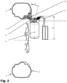
- Fig. 1 a portable repair kit 1 according to the invention for inflating a motor vehicle tire 2 mounted on a rim, wherein the repair kit has an electrically driven compressor (not shown in detail here) as a compressed gas source and an inlet line 3 with which the compressor is connected to the valve and distributor unit, hereinafter referred to as valve unit 4.
- an electrically driven compressor not shown in detail here
- valve unit 4 the valve and distributor unit
- the Fig. 1 shows the portable repair kit 1 according to the invention hanging on a tire, seen from the tire side.
- the Fig. 2 shows the same repair kit 1 hanging on a tire in a sectional view.
- the repair kit is suspended from the inlet or inlet valve 7 of the vehicle tire 2 by means of a detachable mechanical connection of the outlet line 9.
- the repair kit further comprises a sealant container 8 for an automatic sealant that can be filled into the motor vehicle tire, wherein the sealant container 8 is connected to the valve unit 4 for sealant and compressed gas and the valve unit is provided with an outlet line 9 which can be connected to the motor vehicle tire, wherein the outlet line is connected to an inlet or inlet valve 7 of the motor vehicle tire.
- the repair kit further comprises means for supplying energy, in particular plugs and electric cables, and operating and display elements (5, 6) for operation.
- the repair kit has a screw cap 10 arranged at the end of the outlet line for connecting the outlet line 9 to the inlet valve 7 as a temporarily operable, detachable mechanical-pneumatic connection to the vehicle tire or to the tire valve.
- the repair kit 1 hangs on the tire valve in such a way that contact of the repair kit with the ground is unnecessary in all positions of the tire.
- the arrangement of the mechanical-pneumatic connection and the center of gravity of the repair kit are designed such that after the outlet line 9 is connected to the inlet valve 7, the repair kit 1 assumes a position in which the operating and display elements 5, 6 point towards the operator side and the sealant container is in its upright operating position.
- Fig. 1 and Fig. 2 in detail the inventive construction of the repair kit in that the length l of the detachable mechanical connection according to the formula d ⁇ h ⁇ 1 ⁇ 2 r + d ⁇ h is designed, where d is the sidewall height of the vehicle tire, h is the height of the repair kit and r is the rim radius of the wheel. This ensures that in almost all positions of the wheel or the valve inlet or tire valve the repair kit is positioned hanging and even in the lowest position of the valve is positioned at least diagonally hanging in front of the tire sidewall and does not have to stand on the ground.
- the repair kit shown here advantageously has a total weight of less than 1 kg and is therefore light enough to be suspended from the valve without affecting its strength.
Landscapes
- Engineering & Computer Science (AREA)
- Mechanical Engineering (AREA)
- Fittings On The Vehicle Exterior For Carrying Loads, And Devices For Holding Or Mounting Articles (AREA)
- Vehicle Cleaning, Maintenance, Repair, Refitting, And Outriggers (AREA)
Description
- Die Erfindung betrifft einen tragbaren Reparatursatz zum Abdichten und Aufpumpen von Kraftfahrzeugreifen mit einem elektrisch angetriebenen Kompressor als Druckgasquelle, mit einen Dichtmittelbehälter für ein in den Kraftfahrzeugreifen einfüllbares selbsttätiges Dichtmittel, wobei der Dichtmittelbehälter mit einer Ventileinheit für Dichtmittel und Druckgas verbunden ist und die Ventileinheit mit einer an den Kompressor anschließbaren Einlassleitung und einer an den Kraftfahrzeugreifen anschließbaren Auslassleitung versehen ist, wobei die Auslassleitung mit einem Einlass bzw. Einlassventil des Kraftfahrzeugreifens verbindbar ist, sowie mit Mitteln zur Energiezufuhr, insbesondere Stecker und Elektrokabel, und Bedienungs- und Anzeigeelementen für den Betrieb des Reparatursatzes, wobei der Reparatursatz mindestens ein Befestigungsmittel aufweist, mit dessen Hilfe der Reparatursatz im Betriebszustand an einem Fahrzeug temporär befestigbar ist.
- Bei Reifenpannen besteht in aller Regel das Problem, dass - wie beispielsweise bei einem PKW bisher üblich - ein gefüllter und auf einer Felge montierter Reservereifen mitgeführt werden muss, der dann anstelle des Rades mit dem defekten Reifen montiert wird, wonach der defekte Reifen in dem für den Reservereifen vorgesehenen Stauraum im Fahrzeug befestigt werden und später einer Reparatur zugeführt werden muss. Hierzu ist es nicht nur oft notwendig, ein beladenes Fahrzeug auszuräumen, um an den entsprechenden Stauraum zu gelangen, sondern es muss auch das Fahrzeug selbst mit Wagenhebern aufgebockt und eine umständliche Reparaturarbeit durchgeführt werden.
- Bei Fahrzeugen, die nicht mit schlauchlosen Reifen versehen sind, wie etwa bei Fahrrädern, ist es bei einer Reifenpanne nötigt, mit umfangreichem Werkzeug nach der Montage des Reifens den Mantel von der Felge zu entfernen, den Schlauch zu entnehmen und mit entsprechend mitgeführtem Reparaturmaterial zu flicken. Danach muss der Reifen bzw. der Schlauch oft mehrfach aufgepumpt werden, um eine einigermaßen sichere Weiterfahrt zu gewährleisten. Neben der schwierigen Reparaturtätigkeit besteht bei dem bisher bekannten Verfahren der Nachteil, dass die notwendigen Reparaturmaterialien, wie etwa eine entsprechende Pumpe sowie Hebe- und Schraubwerkzeuge, sowie bei nächtlichen Pannen nötige Beleuchtungskörper, in oder bei den entsprechenden Fahrzeugen nur unvollständig oder gar nicht vorhanden oder an den unterschiedlichsten Stellen verstaut sind und lange gesucht werden müssen.
- Um diese Nachteile zu vermeiden, sind bereits Reparatursätze bekannt, die einen Kompressor, ein im Reifen koagulierendes Dichtmittel, meistens ein Latexmilch-Gemisch, die entsprechenden Verbindungsschläuche und die notwendigen Kabelanschlüsse zur Energiezufuhr sowie Schalter, Manometer und Bedienelement beinhalten und somit einen ständig einsetzbaren und vollständigen Reparatursatz bereitstellen, mit dem auf das Mitführen eines auf eine Felge aufgezogenen Reserverades oder auf die ständige Kontrolle anderer Reparaturmaterialien wie Schläuche, verschiedene Werkzeugschlüssel, Wagenheber etc. verzichtet werden kann. Die Reparatursätze / Pannensets sind typischerweise im Kofferraum eines Fahrzeugs untergebracht.
- Handelsübliche Pannensets zur Reifenabdichtung, die einen Kleinkompressor enthalten, können in zwei Systeme unterteilt werden.
- Es gibt einerseits Systeme, bei denen das Abdichtmittel mit Hilfe des Kompressors durch den Reifenventileinsatz gepumpt und danach ohne Unterbrechung der Reifen mit Luft gefüllt wird. Andererseits gibt es Systeme, bei denen zunächst allein Dichtmittel in den Reifen eingefüllt wird. Nachdem das Dichtmittel in den Reifen gedrückt wurde, etwa mit Hilfe einer verformbaren Flasche (Quetsch-Flasche), wird der Reifenventileinsatz wieder eingeschraubt, bevor in einem zweiten Schritt der Kompressor am Reifenventil angeschlossen und der Reifen mit Luft befüllt wird. Üblicherweise stehen dabei Teile des Systems, insbesondere der Kompressor, auf dem Boden neben dem Reifen und sind mit einem ausreichend langen, druckfesten Schlauch mit dem Reifenventil verbunden.
- Es ist bei beiden Systemen darauf zu achten, dass während der Benutzung alle relevanten Systeminformationen (z. B. Druckanzeige) benutzerfreundlich zur Verfügung gestellt werden.
- Wenn solche Reparatursätze gebraucht werden, befindet sich der Nutzer in ungewohnter und ungeübter Situation. Die einzelnen Zubehörteile solcher Reparatursätze müssen daher "zur Hand" sein und in einer Weise miteinander verbunden oder zusammengestellt sein, die sicherstellt, dass alle Funktionsteile sich am richtigen und zum Betrieb vorgesehen Platz befinden und miteinander wirken können. Das ist nicht ganz problemlos zu gewährleisten, insbesondere dann, wenn je nach Betriebszustand zunächst Dichtmittelbehälter und diverse Schlauchverbindungen angeschlossen oder umgebaut werden müssen. Oft werden auch Systemteile verlegt, vergessen oder falsch angeschlossen.
- Zur Erleichterung der Handhabung der Geräte/Reparatursätze offenbart die
EP 1914062 A1 einen Reparatursatz zum Abdichten und Aufpumpen aufblasbarer Gegenstände, der mindestens ein Befestigungsmittel aufweist, mit dessen Hilfe die Einrichtung im Betriebszustand an einem Fahrzeug temporär befestigbar ist. Damit erhält man eine Verbindung zwischen den wichtigsten Bauteilen/Zubehörteilen, so dass alle Zubehörteile des Pannenhilfesets sich beim Einsatz zusammen und am richtigen Platz befinden. - Nun ist der augenblickliche Trend zu größeren Reifenabmessungen diametral zum Trend bei Pannensets, die immer kleiner und kostengünstiger werden. Einer der Zielkonflikte bei der Konstruktion kleiner Pannensets ist u.a. die Länge des Schlauches sowie die Packmaße zum Verstauen des Pannensets im Fahrzeug. Ein besonders kleiner Pannenset benötigt, wenn er auf der Erde neben dem Reifen betrieben werden soll, u.a. einen langen und flexiblen Schlauch als Verbindung zwischen einer Verteilereinheit für Druck- und Dichtmittel und dem Reifenventil, was eben gerade die Packmaße erhöht und ungewünscht ist.
- Für die Erfindung bestand also die Aufgabe, einen tragbaren Reparatursatz als so genannten "Pannenset" bereitzustellen, der kleine Packmaße aufweist, sicher, einfach und möglichst bedienungsfreundlich zu handhaben ist, eine robuste Ausführung aufweist und dazu einfach und preisgünstig herzustellen ist.
- Gelöst wird diese Aufgabe durch die Merkmale des Hauptanspruchs. Weitere vorteilhafte Ausbildungen sind in den Unteransprüchen offenbart.
- Dabei ist der Reparatursatz mit Hilfe einer lösbaren mechanischen Verbindung der Auslassleitung mit dem Einlass bzw. Einlassventil des Fahrzeugreifens hängend befestigt, nämlich vorzugsweise in den meisten Fällen so,, dass ein Kontakt des Reparatursatzes mit dem Untergrund unnötig ist. Der Reparatursatz "hängt" dann am Reifenventil und kann dadurch unabhängig vom Fahrbahnuntergrund eingesetzt werden, kann z.B. bei unebenem oder schlammigem Seitenstreifen ohne weiteres verwendet werden, und es müssen keine separaten Schlauchverbindungen angeschlossen oder umgebaut werden. Der Bediener kann also ohne große Vorbereitungen den Reparatursatz einsetzen, indem er ihn lediglich mit dem Reifenventil verbindet.. Eine vorteilhafte Ausbildung besteht darin, dass nach der Befestigung eine betriebsbereite Ausrichtung des Reparatursatzes auch dann vorhanden ist, wenn kein Kontakt des Reparatursatzes mit dem Untergrund besteht. Unter dem Begriff" betriebsbereite Ausrichtung" versteht man in diesem Zusammenhang ein Zustand, bei der alle Funktionen des Reparatursatzes mindestens für den zur Durchführung der Funktion nötigen Zeitraum gewährleistet sind, d.h. zum Beispiel für den Zeitraum, den das Abdichten und Aufpumpen eines Reifens erfordert. Die betriebsbereite Ausrichtung ist auch dann gewährleistet, wenn kein Kontakt des Reparatursatzes mit dem Untergrund besteht.
- Die Verbindung des Reparatursatzes mit dem Fahrzeug bzw. dem Einlassventil kann dabei mit üblichen Verbindungsmitteln, wie etwa Schlaufen oder Haken direkt am Ventil erfolgen, oder auch, wie es in einer vorteilhaften Weiterbildung vorgesehen ist, mit Hilfe einer Druckgas leitenden, lösbaren mechanischen Verbindung zwischen Auslassleitung und Einlass bzw. Einlassventil am Fahrzeugreifen. Damit ist in einfachster Weise eine mechanische und pneumatische Verbindung gleichzeitig entstanden.
- Eine weitere vorteilhafte Ausbildung besteht darin, dass die Auslassleitung mindestens teilweise als Schlauchstück ausgebildet ist und die lösbare mechanische Verbindung als an dem Schlauchstück befindliche Schraubkappe zur Verbindung des Schlauchstücks mit dem Einlassventil ausgebildet ist. Damit wird eine leicht zu bedienende und auch allseits bekannte Art der Verbindung für den Reparatursatz bereitgestellt, so dass der Bediener keine Schwierigkeiten vor sich sieht, wenn er das System mit dem Reifenventil verbinden will. Hier dient die Verbindung neben der pneumatischen Verbindung auch als mechanische Verbindung, wobei der leicht und klein gebaute Reparatursatz über den Schlauch direkt am Reifenventil hängt. Der Schlauch ist dabei deutlich kürzer als im Stand der Technik und folgt der Maßgabe, nach der im Regelfall verhindert wird, dass der Reparatursatz mit dem Untergrund in Kontakt kommt.
- Natürlich können auch beide vorteilhaften Ausbildungen der Verbindung nebeneinander existieren, also beispielsweise eine Verbindung über einen Schlauch, wobei ein Schraubverschluss am Schlauch kombiniert ist mit einer Schlaufe zur Aufhängung des Reparatursatzes am Ventilanschluss.
- Eine weitere vorteilhafte Ausbildung besteht darin, dass die Anordnung der mechanischen Verbindung so ausgebildet ist, dass nach der Verbindung bzw. Befestigung der Auslassleitung am Einlass bzw. Einlassventil der tragbare Reparatursatz eine Lage einnimmt, bei der die Bedienungs- und Anzeigeelemente zur Bedienerseite zeigen und der Dichtmittelbehälter in seiner Betriebslage sich befindet. So kann beispielsweise ein besonders kurzes Schlauchstück oder auch ein Rohrstutzen als Auslassleitung, welches/welcher mit einer zur Verbindung mit dem Ventil geeigneten Schraubkappe versehen ist, dafür sorgen, dass die mit Bedienungselementen versehene Vorderseite des Kompressorgehäuses sich auf der "richtige" Seite, nämlich auf der Bedienerseite befindet und gleichzeitig die Dichtmittelflasche in ihrer richtigen Stellung steht. Bedienerseite ist ja üblicherweise nahe der Reifenaußenseite, da sich der Bediener ja auf einer Stelle vor dem Reifen bzw. vor der Felge befindet. Damit ist mit ausgesprochen einfachen Mitteln die richtige Lage zum Betrieb des Reparatursatzes festgelegt.
- Eine weitere vorteilhafte Ausbildung besteht darin, dass die lösbare Verbindung eine bewegliche oder flexible Kupplung aufweist, vorzugsweise eine Drehkupplung, und der Schwerpunkt des tragbaren Reparatursatzes so ausgebildet ist, dass nach der Verbindung bzw. Befestigung der Auslassleitung am Einlass bzw. Einlassventil der tragbare Reparatursatz eine Lage einnimmt, bei der die Bedienungs- und Anzeigeelemente zur Bedienerseite zeigen und der Dichtmittelbehälter in seiner Betriebslage sich befindet. Im einfachsten Fall dreht und pendelt der Reparatursatz nach Anschluss an das Reifenventil um Letzteres bzw. den Schlauch als flexiblen Drehpunkt nach unten und richtet sich so aus, dass die Bedienungselemente auch auf der Bedienerseite sind und der Bediener gegebenenfalls nur leichte Korrekturen vornehmen muss, um die beste Position zur Bedienung zu erreichen. Um eine solche stabile Betriebslage zu gewährleisten, liegt der Schwerpunkt des hängenden Reparatursatzes Reifenpannensets im Betriebszustand vorzugweise unterhalb der Aufhängung am Ventil. Schwerkraftbedingt richtet sich das Pannenset also selbsttätig in seine Betriebslage aus. In dieser Betriebslage ist die Ventileinrichtung und das Dichtmittel in der erforderlichen Weise zum Flüssigkeitsspiegel ausgerichtet. Die somit "richtige" Positionierung des Dichtmittelbehälters berücksichtigt dann auch, dass die Höhe des Dichtmittelbehälters größerer ist als seine Breite oder Tiefe, damit um ein möglichst vollständiges Entleeren gesichert ist. Bei den gegebenen Gewichtsverhältnissen ist eine Schwerpunktänderung des Reparatursatzes durch das Auspumpen des Dichtmittels vernachlässigbar in Bezug auf die Position des hängenden Reparatursatzes am Reifen.
- In eben dieser Weise oder auch unterstützend wirkt eine weitere vorteilhafte Ausbildung, die darin besteht, dass die lösbare Verbindung eine bewegliche oder flexible Kupplung aufweist, vorzugsweise eine Drehkupplung, und die Formgebung des tragbaren Reparatursatzes so ausgebildet ist, dass nach der Verbindung bzw. Befestigung der Auslassleitung am Einlass bzw. Einlassventil der tragbare Reparatursatz eine Lage einnimmt, bei der die Bedienungs- und Anzeigeelemente zur Bedienerseite zeigen und der Dichtmittelbehälter in seiner Betriebslage sich befindet.
- Neben den Vorteilen bei der Bedienung stellt der erfindungsgemäße Reparatursatz ein kleineres, leichteres, kostengünstigeres Design bereit, reduziert durch einen kürzeren Schlauch den Platzbedarf und das zugehörige Gehäuse, weist ein geringeres Gesamtgewicht auf und stellt Einsparungen bei den Herstellkosten bereit. Ein verkürzter Schlauch ermöglicht durch eine sehr platzsparende Bauweise neue Möglichkeiten zum Lagern des Reparatursatzes im Fahrzeug, z.B. unterhalb der Fahrzeugsitze.
- Anhand eines Ausführungsbeispiels soll die Erfindung näher erläutert werden.
- Die Figuren sind in der Zusammenschau zu betrachten. Dabei zeigt
Fig. 1 einen erfindungsgemäßen tragbaren Reparatursatz 1 zum Aufpumpen eines auf eine Felge aufgezogenen Kraftfahrzeugreifens 2, wobei der Reparatursatz einen hier nicht im Detail näher dargestellten elektrisch angetriebenen Kompressor als Druckgasquelle aufweist sowie eine Einlassleitung 3, mit der der Kompressor an die Ventil- und Verteilereinheit, im weiteren kurz Ventileinheit 4 angeschlossen ist. - Die
Fig. 1 zeigt den erfindungsgemäßen tragbaren Reparatursatz 1 an einem Reifen hängend von der Reifenseite aus gesehen. DieFig. 2 zeigt denselben Reparatursatz 1 an einem Reifen hängend in einer Schnittansicht. - Der Reparatursatz ist mit Hilfe einer lösbaren mechanischen Verbindung der Auslassleitung 9 an dem Einlass bzw. Einlassventil 7 des Fahrzeugreifens 2 hängend befestigt.
- Der Reparatursatz weist weiterhin einen Dichtmittelbehälter 8 auf für ein in den Kraftfahrzeugreifen einfüllbares selbsttätiges Dichtmittel, wobei der Dichtmittelbehälter 8 mit der Ventileinheit 4 für Dichtmittel und Druckgas verbunden ist und die Ventileinheit mit einer an den Kraftfahrzeugreifen anschließbaren Auslassleitung 9 versehen ist, wobei die Auslassleitung mit einem Einlass bzw. Einlassventil 7 des Kraftfahrzeugreifens verbunden ist.
- Der Reparatursatz weist weiterhin Mittel zur Energiezufuhr, insbesondere Stecker und Elektrokabel, und Bedienungs- und Anzeigeelementen (5, 6) für den Betrieb auf.
- Der Reparatursatz besitzt als temporär betätigbare lösbare mechanisch-pneumatische Verbindung zum Fahrzeugreifen bzw. zum Reifenventil eine am Ende der Auslassleitung angeordnete Schraubkappe 10 zur Verbindung der Auslassleitung 9 mit dem Einlassventil 7.
- Damit hängt bei entsprechend kurz ausgebildeter Auslassleitung 9 der Reparatursatz 1 so an dem Reifenventil, dass in allen Stellungen des Reifens ein Kontakt des Reparatursatzes mit dem Untergrund unnötig ist.
- Die Anordnung und der mechanisch-pneumatischen Verbindung und der Schwerpunkt des Reparatursatzes sind dabei so ausgebildet, dass nach Verbindung der Auslassleitung 9 mit dem Einlassventil 7 der Reparatursatz 1 eine Lage einnimmt, bei der die Bedienungs- und Anzeigeelemente 5, 6 zur Bedienerseite zeigen und der Dichtmittelbehälter sich in seiner aufrechten Betriebslage befindet.
- In der Zusammenschau zeigen
Fig. 1 undFig. 2 im Detail die erfindungsgemässe Konstruktion des Reparatursatzes dahingehend, dass die Länge l der lösbaren mechanischen Verbindung gemäß der Formel
- Der hier gezeigte Reparatursatz weist vorteilhafterweise ein Gesamtgewicht von unter 1 kg auf und ist somit leicht genug um ohne Auswirkungen auf die Festigkeit des Ventils an Letzterem hängend angeordnet zu werden.
-
- 1
- Reparatursatz
- 2
- Kraftfahrzeugreifen
- 3
- Einlassleitung
- 4
- Ventil- und Verteilereinheit/ Ventileinheit des Reparatursatzes
- 5
- Bedienungs- und Anzeigeelement
- 6
- Bedienungs- und Anzeigeelement
- 7
- Einlassventil
- 8
- Dichtmittelbehälter
- 9
- Auslassleitung
- 10
- Schraubkappe
Claims (6)
- Tragbarer Reparatursatz (1) zum Abdichten und Aufpumpen von Fahrzeugreifen, insbesondere Kraftfahrzeugreifen (2) mit einem elektrisch angetriebenen Kompressor als Druckgasquelle, mit einen Dichtmittelbehälter (8) für ein in den Kraftfahrzeugreifen einfüllbares selbsttätiges Dichtmittel, wobei der Dichtmittelbehälter (8) mit einer zum Reparatursatz gehörigen Ventil- und Verteilereinheit (4) für Dichtmittel und Druckgas verbunden ist und die Ventileinheit (4) mit einer an den Kompressor anschließbaren Einlassleitung (3) und einer an den Kraftfahrzeugreifen anschließbaren Auslassleitung (9) versehen ist, wobei die Auslassleitung (9) mit einem Einlass bzw. Einlassventil (7) des Kraftfahrzeugreifens (2) verbindbar ist, sowie mit Mitteln zur Energiezufuhr, insbesondere Stecker und Elektrokabel, und Bedienungs- und Anzeigeelementen (5, 6) für den Betrieb des Reparatursatzes, wobei der Reparatursatz (1) mindestens ein Befestigungsmittel aufweist, mit dessen Hilfe der Reparatursatz im Betriebszustand an einem Fahrzeug temporär befestigbar ist, wobei der Reparatursatz mit Hilfe einer Druckgas leitenden, lösbaren mechanischen Verbindung zwischen Auslassleitung und Einlass bzw. Einlassventil (7) am Fahrzeugreifenventil hängend und ohne Kontakt zum Untergrund in einer betriebsbereiten Ausrichtung befestigbar ist, vorzugsweise die Auslassleitung mindestens teilweise als Schlauchstück und die lösbare mechanische Verbindung als eine an dem Schlauchstück befindliche Schraubkappe zur Verbindung des Schlauchstücks mit dem Einlassventil ausgebildet sind,
dadurch gekennzeichnet, dass die Länge l der lösbaren mechanischen Verbindung gemäß folgender Formel ausgebildet ist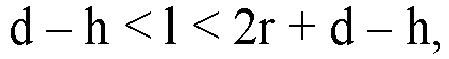
- Tragbarer Reparatursatz nach Anspruch 1, bei der die Anordnung der mechanischen Verbindung so ausgebildet ist, dass nach der Verbindung bzw. Befestigung der Auslassleitung am Einlass bzw. Einlassventil (7) der tragbare Reparatursatz (1) eine Lage einnimmt, bei der die Bedienungs- und Anzeigeelemente (5, 6) zur Bedienerseite zeigen und der Dichtmittelbehälter (8) in seiner Betriebslage sich befindet.
- Tragbarer Reparatursatz nach einem der Ansprüche 1 oder 2, bei der die lösbare Verbindung eine bewegliche oder flexible Kupplung aufweist, vorzugsweise eine Drehkupplung, und der Schwerpunkt des tragbaren Reparatursatzes so ausgebildet ist, dass nach der Verbindung bzw. Befestigung der Auslassleitung am Einlass bzw. Einlassventil (7) der tragbare Reparatursatz (1) eine Lage einnimmt, bei der die Bedienungs- und Anzeigeelemente (5, 6) zur Bedienerseite zeigen und der Dichtmittelbehälter (8) in seiner Betriebslage sich befindet.
- Tragbarer Reparatursatz nach einem der Ansprüche 1 bis 3, bei der die lösbare Verbindung eine bewegliche oder flexible Kupplung aufweist, vorzugsweise eine Drehkupplung, und die Formgebung des tragbaren Reparatursatzes (1) so ausgebildet ist, dass nach der Verbindung bzw. Befestigung der Auslassleitung am Einlass bzw. Einlassventil (7) der tragbare Reparatursatz eine Lage einnimmt, bei der die Bedienungs- und Anzeigeelemente (5, 6) zur Bedienerseite zeigen und der Dichtmittelbehälter (8) in seiner Betriebslage sich befindet.
- Tragbarer Reparatursatz nach einem der Ansprüche 1 bis 4, dessen Gesamtgewicht kleiner als 1,5 kg ist, vorzugsweise kleiner als 1 kg.
- Tragbarer Reparatursatz nach einem der Ansprüche 1 bis 5, bei dem die Unterseite des Dichtmittelbehälters (8) senkrecht zur Schwerkraftrichtung ausgerichtet ist, insbesondere auch nach dem Entleeren.
Applications Claiming Priority (2)
| Application Number | Priority Date | Filing Date | Title |
|---|---|---|---|
| DE102015203972.2A DE102015203972A1 (de) | 2015-03-05 | 2015-03-05 | Tragbarer Reparatursatz |
| PCT/EP2015/078750 WO2016138972A1 (de) | 2015-03-05 | 2015-12-07 | Tragbarer reparatursatz |
Publications (2)
| Publication Number | Publication Date |
|---|---|
| EP3265300A1 EP3265300A1 (de) | 2018-01-10 |
| EP3265300B1 true EP3265300B1 (de) | 2024-12-04 |
Family
ID=54838334
Family Applications (1)
| Application Number | Title | Priority Date | Filing Date |
|---|---|---|---|
| EP15807635.6A Active EP3265300B1 (de) | 2015-03-05 | 2015-12-07 | Tragbarer reparatursatz |
Country Status (5)
| Country | Link |
|---|---|
| EP (1) | EP3265300B1 (de) |
| JP (1) | JP6637073B2 (de) |
| CN (1) | CN107405844B (de) |
| DE (1) | DE102015203972A1 (de) |
| WO (1) | WO2016138972A1 (de) |
Cited By (1)
| Publication number | Priority date | Publication date | Assignee | Title |
|---|---|---|---|---|
| US20240326525A1 (en) * | 2023-03-27 | 2024-10-03 | Nantong Xinyue Technology Co., Ltd. | Automotive tire inflation device |
Families Citing this family (14)
| Publication number | Priority date | Publication date | Assignee | Title |
|---|---|---|---|---|
| JP6586913B2 (ja) | 2016-03-28 | 2019-10-09 | 横浜ゴム株式会社 | パンク修理キット |
| DE102016122735A1 (de) | 2016-11-24 | 2018-05-24 | Kt Projektentwicklungs-Gmbh | Kraftfahrzeug mit einer Verdichteranordnung |
| DE102016122736A1 (de) | 2016-11-24 | 2018-05-24 | Kt Projektentwicklungs-Gmbh | Fahrzeug mit Verdichteranordnung |
| DE102016122739A1 (de) | 2016-11-24 | 2018-05-24 | Kt Projektentwicklungs-Gmbh | Verdichteranordnung mit Wulstzylinderkurve |
| DE102016122738A1 (de) | 2016-11-24 | 2018-05-24 | Kt Projektentwicklungs-Gmbh | Verdichteranordnung mit radialen Kolben |
| DE102017106805A1 (de) | 2017-03-03 | 2018-09-06 | Kt Projektentwicklungs-Gmbh | Verdichteranordnung mit Magnetkopplung |
| JP6900786B2 (ja) * | 2017-05-26 | 2021-07-07 | 横浜ゴム株式会社 | パンク修理キット用容器 |
| JP7271981B2 (ja) | 2019-02-06 | 2023-05-12 | 横浜ゴム株式会社 | パンク修理キット |
| DE102019205091A1 (de) * | 2019-04-09 | 2020-10-15 | Continental Reifen Deutschland Gmbh | Pannenhilfesystem zum Abdichten und Aufpumpen von Kraftfahrzeugluftreifen |
| EP3924195B1 (de) | 2019-04-17 | 2024-06-05 | Santa Cruz Bicycles, LLC | Aufpumpsystem für schlauchlose reifen |
| JP7747641B2 (ja) | 2020-01-27 | 2025-10-01 | クリック コーポレーション | 改善された空気圧バルブシステムおよびそれを使用する方法 |
| US11491925B2 (en) | 2020-08-27 | 2022-11-08 | Honda Motor Co., Ltd. | Storage system for a vehicle and interior compartment of a vehicle having same |
| DE102021101463A1 (de) * | 2021-01-25 | 2022-07-28 | Illinois Tool Works Inc. | Reifenreparaturset und verfahren zum aufblasen und/oder abdichten eines reifens |
| WO2023198298A1 (de) | 2022-12-08 | 2023-10-19 | Kt Projektentwicklungs-Gmbh | Reifenreparaturvorrichtung zur anbringung an einem fahrzeugrad |
Family Cites Families (17)
| Publication number | Priority date | Publication date | Assignee | Title |
|---|---|---|---|---|
| FR2635042B1 (de) * | 1988-08-05 | 1990-09-28 | Michelin & Cie | |
| JP2000309254A (ja) * | 1999-04-26 | 2000-11-07 | Sumitomo Rubber Ind Ltd | タイヤのシール・ポンプアップ装置 |
| ITTO20040121A1 (it) * | 2004-02-27 | 2004-05-27 | Tek Srl | Contenitore per un liquido sigillante per la riparazione di oggetti gonfiabili, in particolare pnematici, e kit di riparazione provvisto di tale contenitore |
| ITTO20040117A1 (it) * | 2004-02-27 | 2004-05-27 | Tek Srl | Kit per il gonfiaggio e la riparazione di articoli gonfiabili, in particolare pneumatici |
| DE202005017071U1 (de) * | 2005-10-28 | 2007-03-15 | Stehle, Michael | Einfüllsystem zum Abdichten und Aufpumpen von Reifen |
| DE202006016087U1 (de) | 2006-10-20 | 2007-01-11 | Continental Aktiengesellschaft | Einrichtung in Form eines Reparatursatzes |
| US7798183B2 (en) * | 2006-10-26 | 2010-09-21 | Illinois Tool Works Inc. | Integrated compressor-tire sealant injection device with large mouth sealant container |
| JP2009056681A (ja) * | 2007-08-31 | 2009-03-19 | Honda Motor Co Ltd | タイヤのパンク修理装置 |
| WO2009119317A1 (ja) * | 2008-03-25 | 2009-10-01 | 住友ゴム工業株式会社 | タイヤのパンク修理装置 |
| JP5054627B2 (ja) * | 2008-07-15 | 2012-10-24 | 住友ゴム工業株式会社 | シーリング剤容器の蓋ユニット |
| US8640744B2 (en) * | 2009-01-07 | 2014-02-04 | Trydel Research Pty. Ltd. | Apparatus for repairing and inflating of damaged inflatable articles |
| WO2012060296A1 (ja) * | 2010-11-05 | 2012-05-10 | 住友ゴム工業株式会社 | パンク修理キット |
| DE102012100636A1 (de) * | 2012-01-26 | 2013-08-01 | Continental Reifen Deutschland Gmbh | Rückflusssicherung |
| WO2013120261A1 (zh) * | 2012-02-16 | 2013-08-22 | Jhou Wen-San | 车载用空气压缩机装置 |
| US9259982B2 (en) * | 2012-10-05 | 2016-02-16 | Consumer Products International Llc. | Currency operated tire inflation and repair apparatus and methods |
| JP5321726B1 (ja) * | 2012-12-20 | 2013-10-23 | 横浜ゴム株式会社 | パンク修理装置 |
| DK2955071T3 (en) * | 2013-02-07 | 2018-02-05 | Wen San Chou | Air compressor device for supplying air and filling of rubber |
-
2015
- 2015-03-05 DE DE102015203972.2A patent/DE102015203972A1/de active Pending
- 2015-12-07 EP EP15807635.6A patent/EP3265300B1/de active Active
- 2015-12-07 JP JP2017560872A patent/JP6637073B2/ja active Active
- 2015-12-07 WO PCT/EP2015/078750 patent/WO2016138972A1/de not_active Ceased
- 2015-12-07 CN CN201580077441.4A patent/CN107405844B/zh active Active
Cited By (1)
| Publication number | Priority date | Publication date | Assignee | Title |
|---|---|---|---|---|
| US20240326525A1 (en) * | 2023-03-27 | 2024-10-03 | Nantong Xinyue Technology Co., Ltd. | Automotive tire inflation device |
Also Published As
| Publication number | Publication date |
|---|---|
| JP2018510094A (ja) | 2018-04-12 |
| CN107405844A (zh) | 2017-11-28 |
| JP6637073B2 (ja) | 2020-01-29 |
| CN107405844B (zh) | 2020-04-07 |
| EP3265300A1 (de) | 2018-01-10 |
| WO2016138972A1 (de) | 2016-09-09 |
| DE102015203972A1 (de) | 2016-09-08 |
Similar Documents
| Publication | Publication Date | Title |
|---|---|---|
| EP3265300B1 (de) | Tragbarer reparatursatz | |
| EP0972616B1 (de) | Reparatursatz mit einem tragbaren Behälter | |
| WO2009065653A1 (de) | Vorrichtung mit einer schaltmarkierung zum abdichten und aufpumpen aufblasbarer gegenstände | |
| EP1940604B1 (de) | Einfüllsystem zum abdichten und aufpumpen von reifen | |
| EP1914062A1 (de) | Einrichtung in Form eines Reparatursatzes | |
| EP3383630B1 (de) | Vorrichtung zum abdichten und aufpumpen von kraftfahrzeugreifen | |
| DE102007053241A1 (de) | Vorrichtung mit einer Ventileinheit zum Abdichten und Aufpumpen aufblasbarer Gegenstände | |
| DE102008033477B4 (de) | Vorrichtung zum Einbringen von Luft und/oder Abdichtmittel in einen Reifen | |
| EP2276624B1 (de) | Pannenhilfesystem | |
| DE19961020A1 (de) | Automatische Reifenluftdruckregulierung mit intregierter Reifenpannenbehebung für alle Kraftfahrzeuge | |
| EP3265346B1 (de) | Tragbare kompressor-einrichtung | |
| EP2196305B1 (de) | Verfahren zum Betrieb eines Pannenhilfesystems und Pannenhilfesystem | |
| WO2006133961A2 (de) | Einrichtung zum zuführen von dichtungsflüssigkeit in einen luftreifen | |
| CH711160A1 (de) | Drucksicherungs-Vorrichtung für Druckluft-gefüllte Räder und Verfahren dazu. | |
| DE112016005755B4 (de) | Reparatureinrichtung und verfahren | |
| EP2212101B1 (de) | Vorrichtung mit einer steckverbindung zum abdichten und aufpumpen aufblasbarer gegenstände | |
| DE202008007517U1 (de) | Pannenhilfesystem | |
| EP1275532B1 (de) | Reifenventilanordnung für ein Fahrzeugluftreifen mit Notlaufschlauch | |
| DE102019210757A1 (de) | Verfahren zum Abdichten und/oder Aufpumpen von Fahrzeugluftreifen auf einem Fahrzeugrad sowie Fahrzeugrad zur Durchführung des Verfahrens | |
| EP3953161B1 (de) | Pannenhilfesystem zum abdichten und aufpumpen von kraftfahrzeugluftreifen | |
| DE202008005408U1 (de) | Pannenhilfesystem | |
| WO2025031569A1 (de) | Reifenreparaturvorrichtung zur anbringung an einem fahrzeugrad | |
| DE102022002574A1 (de) | Radkappe-Luftpumpe | |
| DE19906952A1 (de) | Verbindungsleitung | |
| DE102019210742A1 (de) | Verfahren zum Abdichten und/oder Aufpumpen von Fahrzeugluftreifen auf einem Fahrzeugrad sowie Fahrzeugrad zur Durchführung des Verfahrens |
Legal Events
| Date | Code | Title | Description |
|---|---|---|---|
| STAA | Information on the status of an ep patent application or granted ep patent |
Free format text: STATUS: THE INTERNATIONAL PUBLICATION HAS BEEN MADE |
|
| PUAI | Public reference made under article 153(3) epc to a published international application that has entered the european phase |
Free format text: ORIGINAL CODE: 0009012 |
|
| STAA | Information on the status of an ep patent application or granted ep patent |
Free format text: STATUS: REQUEST FOR EXAMINATION WAS MADE |
|
| 17P | Request for examination filed |
Effective date: 20171005 |
|
| AK | Designated contracting states |
Kind code of ref document: A1 Designated state(s): AL AT BE BG CH CY CZ DE DK EE ES FI FR GB GR HR HU IE IS IT LI LT LU LV MC MK MT NL NO PL PT RO RS SE SI SK SM TR |
|
| AX | Request for extension of the european patent |
Extension state: BA ME |
|
| RIN1 | Information on inventor provided before grant (corrected) |
Inventor name: DETERING, RAINER Inventor name: HUANG, DANQING Inventor name: BIALACH, PHILIP MATHIAS Inventor name: ZAUM, CHRISTOPHER |
|
| DAV | Request for validation of the european patent (deleted) | ||
| DAX | Request for extension of the european patent (deleted) | ||
| RAP1 | Party data changed (applicant data changed or rights of an application transferred) |
Owner name: CONTINENTAL REIFEN DEUTSCHLAND GMBH |
|
| STAA | Information on the status of an ep patent application or granted ep patent |
Free format text: STATUS: EXAMINATION IS IN PROGRESS |
|
| 17Q | First examination report despatched |
Effective date: 20210323 |
|
| RAP3 | Party data changed (applicant data changed or rights of an application transferred) |
Owner name: CONTINENTAL REIFEN DEUTSCHLAND GMBH |
|
| GRAP | Despatch of communication of intention to grant a patent |
Free format text: ORIGINAL CODE: EPIDOSNIGR1 |
|
| STAA | Information on the status of an ep patent application or granted ep patent |
Free format text: STATUS: GRANT OF PATENT IS INTENDED |
|
| INTG | Intention to grant announced |
Effective date: 20240715 |
|
| GRAS | Grant fee paid |
Free format text: ORIGINAL CODE: EPIDOSNIGR3 |
|
| GRAA | (expected) grant |
Free format text: ORIGINAL CODE: 0009210 |
|
| STAA | Information on the status of an ep patent application or granted ep patent |
Free format text: STATUS: THE PATENT HAS BEEN GRANTED |
|
| P01 | Opt-out of the competence of the unified patent court (upc) registered |
Free format text: CASE NUMBER: APP_57344/2024 Effective date: 20241021 |
|
| AK | Designated contracting states |
Kind code of ref document: B1 Designated state(s): AL AT BE BG CH CY CZ DE DK EE ES FI FR GB GR HR HU IE IS IT LI LT LU LV MC MK MT NL NO PL PT RO RS SE SI SK SM TR |
|
| REG | Reference to a national code |
Ref country code: GB Ref legal event code: FG4D Free format text: NOT ENGLISH |
|
| REG | Reference to a national code |
Ref country code: CH Ref legal event code: EP |
|
| REG | Reference to a national code |
Ref country code: DE Ref legal event code: R096 Ref document number: 502015016998 Country of ref document: DE |
|
| REG | Reference to a national code |
Ref country code: IE Ref legal event code: FG4D Free format text: LANGUAGE OF EP DOCUMENT: GERMAN |
|
| REG | Reference to a national code |
Ref country code: LT Ref legal event code: MG9D |
|
| REG | Reference to a national code |
Ref country code: NL Ref legal event code: MP Effective date: 20241204 |
|
| PG25 | Lapsed in a contracting state [announced via postgrant information from national office to epo] |
Ref country code: HR Free format text: LAPSE BECAUSE OF FAILURE TO SUBMIT A TRANSLATION OF THE DESCRIPTION OR TO PAY THE FEE WITHIN THE PRESCRIBED TIME-LIMIT Effective date: 20241204 |
|
| PG25 | Lapsed in a contracting state [announced via postgrant information from national office to epo] |
Ref country code: FI Free format text: LAPSE BECAUSE OF FAILURE TO SUBMIT A TRANSLATION OF THE DESCRIPTION OR TO PAY THE FEE WITHIN THE PRESCRIBED TIME-LIMIT Effective date: 20241204 |
|
| PG25 | Lapsed in a contracting state [announced via postgrant information from national office to epo] |
Ref country code: BG Free format text: LAPSE BECAUSE OF FAILURE TO SUBMIT A TRANSLATION OF THE DESCRIPTION OR TO PAY THE FEE WITHIN THE PRESCRIBED TIME-LIMIT Effective date: 20241204 |
|
| PG25 | Lapsed in a contracting state [announced via postgrant information from national office to epo] |
Ref country code: ES Free format text: LAPSE BECAUSE OF FAILURE TO SUBMIT A TRANSLATION OF THE DESCRIPTION OR TO PAY THE FEE WITHIN THE PRESCRIBED TIME-LIMIT Effective date: 20241204 |
|
| PG25 | Lapsed in a contracting state [announced via postgrant information from national office to epo] |
Ref country code: NO Free format text: LAPSE BECAUSE OF FAILURE TO SUBMIT A TRANSLATION OF THE DESCRIPTION OR TO PAY THE FEE WITHIN THE PRESCRIBED TIME-LIMIT Effective date: 20250304 |
|
| PG25 | Lapsed in a contracting state [announced via postgrant information from national office to epo] |
Ref country code: LV Free format text: LAPSE BECAUSE OF FAILURE TO SUBMIT A TRANSLATION OF THE DESCRIPTION OR TO PAY THE FEE WITHIN THE PRESCRIBED TIME-LIMIT Effective date: 20241204 Ref country code: GR Free format text: LAPSE BECAUSE OF FAILURE TO SUBMIT A TRANSLATION OF THE DESCRIPTION OR TO PAY THE FEE WITHIN THE PRESCRIBED TIME-LIMIT Effective date: 20250305 |
|
| PG25 | Lapsed in a contracting state [announced via postgrant information from national office to epo] |
Ref country code: RS Free format text: LAPSE BECAUSE OF FAILURE TO SUBMIT A TRANSLATION OF THE DESCRIPTION OR TO PAY THE FEE WITHIN THE PRESCRIBED TIME-LIMIT Effective date: 20250304 |
|
| PG25 | Lapsed in a contracting state [announced via postgrant information from national office to epo] |
Ref country code: NL Free format text: LAPSE BECAUSE OF FAILURE TO SUBMIT A TRANSLATION OF THE DESCRIPTION OR TO PAY THE FEE WITHIN THE PRESCRIBED TIME-LIMIT Effective date: 20241204 |
|
| PG25 | Lapsed in a contracting state [announced via postgrant information from national office to epo] |
Ref country code: SM Free format text: LAPSE BECAUSE OF FAILURE TO SUBMIT A TRANSLATION OF THE DESCRIPTION OR TO PAY THE FEE WITHIN THE PRESCRIBED TIME-LIMIT Effective date: 20241204 |
|
| PG25 | Lapsed in a contracting state [announced via postgrant information from national office to epo] |
Ref country code: PL Free format text: LAPSE BECAUSE OF FAILURE TO SUBMIT A TRANSLATION OF THE DESCRIPTION OR TO PAY THE FEE WITHIN THE PRESCRIBED TIME-LIMIT Effective date: 20241204 |
|
| PG25 | Lapsed in a contracting state [announced via postgrant information from national office to epo] |
Ref country code: IS Free format text: LAPSE BECAUSE OF FAILURE TO SUBMIT A TRANSLATION OF THE DESCRIPTION OR TO PAY THE FEE WITHIN THE PRESCRIBED TIME-LIMIT Effective date: 20250404 |
|
| PG25 | Lapsed in a contracting state [announced via postgrant information from national office to epo] |
Ref country code: PT Free format text: LAPSE BECAUSE OF FAILURE TO SUBMIT A TRANSLATION OF THE DESCRIPTION OR TO PAY THE FEE WITHIN THE PRESCRIBED TIME-LIMIT Effective date: 20250404 |
|
| PG25 | Lapsed in a contracting state [announced via postgrant information from national office to epo] |
Ref country code: EE Free format text: LAPSE BECAUSE OF FAILURE TO SUBMIT A TRANSLATION OF THE DESCRIPTION OR TO PAY THE FEE WITHIN THE PRESCRIBED TIME-LIMIT Effective date: 20241204 |
|
| PG25 | Lapsed in a contracting state [announced via postgrant information from national office to epo] |
Ref country code: RO Free format text: LAPSE BECAUSE OF FAILURE TO SUBMIT A TRANSLATION OF THE DESCRIPTION OR TO PAY THE FEE WITHIN THE PRESCRIBED TIME-LIMIT Effective date: 20241204 |
|
| PG25 | Lapsed in a contracting state [announced via postgrant information from national office to epo] |
Ref country code: SK Free format text: LAPSE BECAUSE OF FAILURE TO SUBMIT A TRANSLATION OF THE DESCRIPTION OR TO PAY THE FEE WITHIN THE PRESCRIBED TIME-LIMIT Effective date: 20241204 |
|
| PG25 | Lapsed in a contracting state [announced via postgrant information from national office to epo] |
Ref country code: CZ Free format text: LAPSE BECAUSE OF FAILURE TO SUBMIT A TRANSLATION OF THE DESCRIPTION OR TO PAY THE FEE WITHIN THE PRESCRIBED TIME-LIMIT Effective date: 20241204 |
|
| PG25 | Lapsed in a contracting state [announced via postgrant information from national office to epo] |
Ref country code: IT Free format text: LAPSE BECAUSE OF FAILURE TO SUBMIT A TRANSLATION OF THE DESCRIPTION OR TO PAY THE FEE WITHIN THE PRESCRIBED TIME-LIMIT Effective date: 20241204 |
|
| REG | Reference to a national code |
Ref country code: CH Ref legal event code: PL |
|
| PG25 | Lapsed in a contracting state [announced via postgrant information from national office to epo] |
Ref country code: LU Free format text: LAPSE BECAUSE OF NON-PAYMENT OF DUE FEES Effective date: 20241207 |
|
| REG | Reference to a national code |
Ref country code: DE Ref legal event code: R097 Ref document number: 502015016998 Country of ref document: DE |
|
| PG25 | Lapsed in a contracting state [announced via postgrant information from national office to epo] |
Ref country code: SE Free format text: LAPSE BECAUSE OF FAILURE TO SUBMIT A TRANSLATION OF THE DESCRIPTION OR TO PAY THE FEE WITHIN THE PRESCRIBED TIME-LIMIT Effective date: 20241204 |
|
| PG25 | Lapsed in a contracting state [announced via postgrant information from national office to epo] |
Ref country code: MC Free format text: LAPSE BECAUSE OF FAILURE TO SUBMIT A TRANSLATION OF THE DESCRIPTION OR TO PAY THE FEE WITHIN THE PRESCRIBED TIME-LIMIT Effective date: 20241204 |
|
| REG | Reference to a national code |
Ref country code: BE Ref legal event code: MM Effective date: 20241231 |
|
| PG25 | Lapsed in a contracting state [announced via postgrant information from national office to epo] |
Ref country code: DK Free format text: LAPSE BECAUSE OF FAILURE TO SUBMIT A TRANSLATION OF THE DESCRIPTION OR TO PAY THE FEE WITHIN THE PRESCRIBED TIME-LIMIT Effective date: 20241204 |
|
| PLBE | No opposition filed within time limit |
Free format text: ORIGINAL CODE: 0009261 |
|
| STAA | Information on the status of an ep patent application or granted ep patent |
Free format text: STATUS: NO OPPOSITION FILED WITHIN TIME LIMIT |
|
| PG25 | Lapsed in a contracting state [announced via postgrant information from national office to epo] |
Ref country code: BE Free format text: LAPSE BECAUSE OF NON-PAYMENT OF DUE FEES Effective date: 20241231 |
|
| PG25 | Lapsed in a contracting state [announced via postgrant information from national office to epo] |
Ref country code: CH Free format text: LAPSE BECAUSE OF NON-PAYMENT OF DUE FEES Effective date: 20241231 |
|
| PG25 | Lapsed in a contracting state [announced via postgrant information from national office to epo] |
Ref country code: IE Free format text: LAPSE BECAUSE OF NON-PAYMENT OF DUE FEES Effective date: 20241207 |
|
| 26N | No opposition filed |
Effective date: 20250905 |
|
| PGFP | Annual fee paid to national office [announced via postgrant information from national office to epo] |
Ref country code: GB Payment date: 20251219 Year of fee payment: 11 |
|
| PG25 | Lapsed in a contracting state [announced via postgrant information from national office to epo] |
Ref country code: FR Free format text: LAPSE BECAUSE OF NON-PAYMENT OF DUE FEES Effective date: 20250204 |
|
| REG | Reference to a national code |
Ref country code: AT Ref legal event code: MM01 Ref document number: 1747733 Country of ref document: AT Kind code of ref document: T Effective date: 20241207 |
|
| PG25 | Lapsed in a contracting state [announced via postgrant information from national office to epo] |
Ref country code: CY Free format text: LAPSE BECAUSE OF FAILURE TO SUBMIT A TRANSLATION OF THE DESCRIPTION OR TO PAY THE FEE WITHIN THE PRESCRIBED TIME-LIMIT; INVALID AB INITIO Effective date: 20151207 |
|
| PGFP | Annual fee paid to national office [announced via postgrant information from national office to epo] |
Ref country code: DE Payment date: 20251231 Year of fee payment: 11 |
|
| PG25 | Lapsed in a contracting state [announced via postgrant information from national office to epo] |
Ref country code: AT Free format text: LAPSE BECAUSE OF NON-PAYMENT OF DUE FEES Effective date: 20241207 |