EP3263870A1 - Vorrichtung zur verstellung von komponenten einer verbrennungskraftmaschine - Google Patents
Vorrichtung zur verstellung von komponenten einer verbrennungskraftmaschine Download PDFInfo
- Publication number
- EP3263870A1 EP3263870A1 EP17171018.9A EP17171018A EP3263870A1 EP 3263870 A1 EP3263870 A1 EP 3263870A1 EP 17171018 A EP17171018 A EP 17171018A EP 3263870 A1 EP3263870 A1 EP 3263870A1
- Authority
- EP
- European Patent Office
- Prior art keywords
- spring
- lever
- drive shaft
- stop
- cam
- Prior art date
- Legal status (The legal status is an assumption and is not a legal conclusion. Google has not performed a legal analysis and makes no representation as to the accuracy of the status listed.)
- Granted
Links
Images

Classifications
-
- F—MECHANICAL ENGINEERING; LIGHTING; HEATING; WEAPONS; BLASTING
- F02—COMBUSTION ENGINES; HOT-GAS OR COMBUSTION-PRODUCT ENGINE PLANTS
- F02D—CONTROLLING COMBUSTION ENGINES
- F02D11/00—Arrangements for, or adaptations to, non-automatic engine control initiation means, e.g. operator initiated
- F02D11/04—Arrangements for, or adaptations to, non-automatic engine control initiation means, e.g. operator initiated characterised by mechanical control linkages
-
- F—MECHANICAL ENGINEERING; LIGHTING; HEATING; WEAPONS; BLASTING
- F02—COMBUSTION ENGINES; HOT-GAS OR COMBUSTION-PRODUCT ENGINE PLANTS
- F02D—CONTROLLING COMBUSTION ENGINES
- F02D41/00—Electrical control of supply of combustible mixture or its constituents
- F02D41/0002—Controlling intake air
-
- F—MECHANICAL ENGINEERING; LIGHTING; HEATING; WEAPONS; BLASTING
- F02—COMBUSTION ENGINES; HOT-GAS OR COMBUSTION-PRODUCT ENGINE PLANTS
- F02D—CONTROLLING COMBUSTION ENGINES
- F02D9/00—Controlling engines by throttling air or fuel-and-air induction conduits or exhaust conduits
- F02D9/08—Throttle valves specially adapted therefor; Arrangements of such valves in conduits
- F02D9/10—Throttle valves specially adapted therefor; Arrangements of such valves in conduits having pivotally-mounted flaps
- F02D9/1065—Mechanical control linkage between an actuator and the flap, e.g. including levers, gears, springs, clutches, limit stops of the like
-
- F—MECHANICAL ENGINEERING; LIGHTING; HEATING; WEAPONS; BLASTING
- F02—COMBUSTION ENGINES; HOT-GAS OR COMBUSTION-PRODUCT ENGINE PLANTS
- F02D—CONTROLLING COMBUSTION ENGINES
- F02D11/00—Arrangements for, or adaptations to, non-automatic engine control initiation means, e.g. operator initiated
- F02D11/06—Arrangements for, or adaptations to, non-automatic engine control initiation means, e.g. operator initiated characterised by non-mechanical control linkages, e.g. fluid control linkages or by control linkages with power drive or assistance
- F02D11/10—Arrangements for, or adaptations to, non-automatic engine control initiation means, e.g. operator initiated characterised by non-mechanical control linkages, e.g. fluid control linkages or by control linkages with power drive or assistance of the electric type
-
- F—MECHANICAL ENGINEERING; LIGHTING; HEATING; WEAPONS; BLASTING
- F02—COMBUSTION ENGINES; HOT-GAS OR COMBUSTION-PRODUCT ENGINE PLANTS
- F02D—CONTROLLING COMBUSTION ENGINES
- F02D9/00—Controlling engines by throttling air or fuel-and-air induction conduits or exhaust conduits
- F02D9/02—Controlling engines by throttling air or fuel-and-air induction conduits or exhaust conduits concerning induction conduits
- F02D2009/0201—Arrangements; Control features; Details thereof
-
- Y—GENERAL TAGGING OF NEW TECHNOLOGICAL DEVELOPMENTS; GENERAL TAGGING OF CROSS-SECTIONAL TECHNOLOGIES SPANNING OVER SEVERAL SECTIONS OF THE IPC; TECHNICAL SUBJECTS COVERED BY FORMER USPC CROSS-REFERENCE ART COLLECTIONS [XRACs] AND DIGESTS
- Y02—TECHNOLOGIES OR APPLICATIONS FOR MITIGATION OR ADAPTATION AGAINST CLIMATE CHANGE
- Y02T—CLIMATE CHANGE MITIGATION TECHNOLOGIES RELATED TO TRANSPORTATION
- Y02T10/00—Road transport of goods or passengers
- Y02T10/10—Internal combustion engine [ICE] based vehicles
- Y02T10/40—Engine management systems
Definitions
- the present invention relates to a device for adjusting components of an internal combustion engine.
- the device comprises an electric drive unit, a drive shaft, which is rotatable about the electric drive unit, a lever which is rotatably connected to the drive shaft and whose rotation angle is limited in a first position by a first stop in a first direction of rotation and its rotation angle in one second position is limited by a second stop in an opposite direction of rotation, and a spring which is eccentrically connected to the shaft with the lever and over which the lever is loaded depending on its position either in the direction of the first stop or the second stop.
- Actuators of this type are used to adjust switching flaps for opening or closing a flow channel.
- the switching flaps must be mobile in two defined end positions. For example, when a pulsating flow in the flow channel occurs, it is necessary that the switching flap is held with holding force in the end positions.
- springs are usually used in a first end position, while the second end position often has to be held by the electric motor.
- To reduce this power consumption in the one end position was in the DE 10 2005 052 966 A1 proposed an adjusting device for adjusting components in an internal combustion engine, which comprises a bistable spring element which loads a pivotable part of the adjusting device in the direction of two defined by a respective mechanical stop limit positions. In these two end positions, the pivotable part must be kept energy-efficient.
- the prior art has the disadvantage that only two positions can be kept energy efficient. When taking an intermediate position, a holding energy is applied by the drive unit.
- the object of the present invention is thus to provide a device for adjusting components of an internal combustion engine, by means of which an intermediate position of the lever between the first and the second position, without having to supply energy from the outside, can be maintained.
- the inventive device for adjusting components of an internal combustion engine comprises a shaft rotating with the cam having an eccentric to the cam cam contour, which cooperates with a detent spring such that the shaft and the lever between the first position and the second position in a Lock third position.
- a cam according to the present invention is a constructive element which deviates from a rotationally symmetric shape by a formed cam contour.
- the cam contour is designed in such a way that the latching compression spring engages with the cam contour in a third position.
- the lever thus has to the two positions of the lever on a third position. As a result, the lever has improved adjustability.
- the third position can be kept as well as the first position and the second position without energy. This improves the energy consumption of the device.
- a flap is mounted on the drive shaft, which is rotatable in a flow housing. This flap regulates by adjusting the currents in the flow housing. By the third position, the flap can occupy another position energy efficient, so that the adjustability of the flap is improved in the flow housing.
- a first end of the spring is attached to a suspension point on the lever and an opposite second end of the spring is secured to the flow housing.
- the third position in a torque-neutral position of the spring Under a torque-neutral position of the spring according to the present invention is understood that the force exerted by the spring on the lever, in the direction of the lever extension in this position. The lever thus experiences neither a torque in the direction of the first rotational direction nor a torque in the direction of the opposite direction of rotation. In the third position, the torque of the lever is thus zero. As a result, the lever is safe, without supplying holding energy, in the third position durable.
- the third position is located centrally between the first position and the second position. Since displacement of the third position generally results in displacement of the suspension point of the second end of the spring, non-central positioning of the third position results in different retention forces in the first and second positions. Thus, for example, the holding force of the spring in the first position can be much higher than in the second position. Consequently, a central arrangement of the third position leads to equal holding forces in the first and the second position.
- the spring is preferably a coil spring.
- a coil spring is an economically producible component which can be used according to the required spring parameters as needed.
- the second end of the spring is arranged within the maximum angle of rotation which can be traversed by the lever. Due to the stops of the maximum traversable angle of rotation is formed from a resulting between the first and the second position angle.
- the second end of the spring can be arranged within a wide range.
- the position of the second end is selected as a function of the third position, so that the spring in the third position as possible exerts no torque on the lever, so that the third position can be securely held.
- the spring is preferably a compression spring. Since the spring force of the compression spring can be very high, a reliable holding force in the first and second positions without additional holding energy is ensured.
- the second end of the spring is arranged within a region which is arranged axially symmetrically with respect to the shaft axis with respect to the shaft axis through which the lever can be driven.
- An axially symmetric region with respect to the shaft axis is to be understood as meaning that this region has been mirrored on a mirror axis passing through the shaft axis, so that a connecting line between each original point and the mirror point is perpendicular to the mirror axis.
- the area according to the invention is thus a mirrored area of the maximum angle of rotation which can be traversed by the lever.
- the spring is preferably a tension spring.
- the tension spring has the advantage that the risk of buckling of the spring is excluded.
- the cam contour is formed in a preferred embodiment as a recess.
- the recess forms a concave cam contour.
- the recess may be formed, for example, as a half-moon-shaped recess. Since a contact point of a correspondingly shaped mating contour with the cam thus lies on an axis of symmetry of the detent compression spring, the detent compression spring is generally loaded in an axial direction of the detent compression spring.
- the detent pressure spring in the recess of the cam springs.
- the latching compression spring and the recess form a positive connection. Through this connection, the lever is safely preserved in the third position.
- the device has a latching body which can be pressed into the recess of the cam via the latching compression spring.
- the locking body can be easily formed with an exact convex mating contour to the cam contour, so that the lever can be kept in the third position with little play. In addition, the fixation in the third position is improved.
- the stops are formed on the flow housing.
- the attacks can be provided without additional components.
- the stops are formed on a side opposite to the drive unit side of the flow housing. This makes it possible, according to the space, to arrange the attacks also remotely to the drive unit.
- the device according to the invention thus has the advantage that a third position is adjustable, which can be maintained without supplying energy from the outside. This also increases the adjustability of such a device.
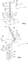
- FIG. 1 shows a device 10 according to the invention.
- the device has a lever 14 which is non-rotatably connected to a drive shaft 18.
- the drive shaft 18 is drivable via an electric drive unit, not shown.
- the lever 14 is shown in a first position. In the first position, the angle of rotation ⁇ of the lever 14 is limited in a first direction of rotation by a first stop 22.
- the first stop 22 is formed on a flow housing 24.
- the device 10 has a spring 26 provided as a tension spring.
- the spring 26, which is designed as a helical spring, is mounted eccentrically to the drive shaft 18 at a suspension point 30 on the lever 14.
- An opposite second end 34 of the spring 26 is on Flow housing 24 attached.
- the second end 34 of the spring 26 is arranged within a region 36, which is arranged axially symmetrically with respect to a shaft axis 38 with respect to a shaft axis 38 which can be traversed by the lever 14.
- the spring 26 loads the lever 14 in response to its position either in the direction of the first stop 22 or a second stop 42.
- the spring 26 thus holds the lever 14 in the first position.
- the drive shaft 18 is rotated via the electric drive unit.
- the device 10 additionally has a cam 46 which rotates together with the drive shaft 18.
- the cam 46 has a cam contour 50, which is formed in the form of a crescent-shaped recess 52.
- the cam 46 cooperates with a latching compression spring 54, which is designed as a leaf spring.
- the latching compression spring 54 has a contour 58, which is a positive contour of the cam contour 50.
- FIG. 2 shows the device 10 in which the lever 14 is in a second position.
- the second position differs from the first position of the lever 14 in that a direction of rotation opposite to the first direction of rotation is limited by the second stop 42.
- FIG. 3 shows the device 10 in which the lever 14 is in a third position.
- the third position is provided centrally between the first and the second position.
- the latching compression spring 54 is locked to the cam contour 50.
- the detent compression spring 54 springs to the cam contour 50 a.
- a direction of the force of the spring 26 extends in a longitudinal direction of the lever 14.
- the lever 14 is thus in a torque-neutral position.
- the lever 14 can thus be kept in the third position without being supplied by holding energy.
- FIG. 4 shows a second embodiment of the device 10 according to the invention, wherein in the following description, like reference numerals are used for equivalent parts.
- the lever 14 in a second position.
- the second embodiment differs from the first embodiment in that a compression spring is used for the spring 26 instead of a tension spring.
- the spring 26 is also a helical spring.
- the second end 34 of the spring 26 is disposed within the maximum traversable by the lever 14 angle of rotation ⁇ on the flow housing 24.
- the spring 26 is provided to a large extent in a shaped as a hollow cylinder sleeve 59, which guides the spring 26.
- the sleeve 59 is formed from a first sleeve part 60 and a telescopically displaceable on the first sleeve part 60 second sleeve part 61.
- the cam 46 cooperates with a latching body 62, which is pressed by the latching compression spring 54 in the direction of the cam 46.
- the latching compression spring 54 which is designed as a helical spring, and the latching body 62 are provided in a recess 66.
- the latching body 62 has, on a side facing the cam 46, a positive contour matching the cam contour 50. In a third position, the latching body 62 can thus spring into the cam contour 50, so that the latching body 62 locks the lever 14 in the third position.
- the device according to the invention is not limited to the described embodiments.
- the various options for the spring with the formed as a leaf spring detent compression spring or the detent body can be combined.
- the device according to the invention has the advantage that a third position is adjustable, which is durable without additional holding energy. This also increases the adjustability of such a device.
Landscapes
- Engineering & Computer Science (AREA)
- Chemical & Material Sciences (AREA)
- Combustion & Propulsion (AREA)
- Mechanical Engineering (AREA)
- General Engineering & Computer Science (AREA)
- Transmission Devices (AREA)
- Control Of Throttle Valves Provided In The Intake System Or In The Exhaust System (AREA)
Abstract
Description
- Die vorliegende Erfindung betrifft eine Vorrichtung zur Verstellung von Komponenten einer Verbrennungskraftmaschine. Die Vorrichtung umfasst eine elektrische Antriebseinheit, eine Antriebswelle, welche über die elektrische Antriebseinheit drehbar ist, einen Hebel, welcher drehfest mit der Antriebswelle verbunden ist und dessen Drehwinkel in einer ersten Stellung durch einen ersten Anschlag in einer ersten Drehrichtung begrenzt ist und dessen Drehwinkel in einer zweiten Stellung durch einen zweiten Anschlag in einer entgegengesetzten Drehrichtung begrenzt ist, und eine Feder, welche exzentrisch zur Welle mit dem Hebel verbunden ist und über die der Hebel in Abhängigkeit seiner Position entweder in Richtung des ersten Anschlags oder des zweiten Anschlags belastet ist.
- Stellvorrichtungen dieser Art dienen zur Verstellung von Schaltklappen zum Öffnen oder Schließen eines Strömungskanals. Die Schaltklappen müssen dabei in zwei definierte Endstellungen fahrbar sein. Beispielsweise bei Auftreten einer pulsierenden Strömung im Strömungskanal ist es erforderlich, dass die Schaltklappe mit Haltekraft in den Endstellungen gehalten wird. Hierzu werden zumeist in einer ersten Endstellung Federn verwendet, während die zweite Endstellung häufig vom Elektromotor gehalten werden muss. Um diesen Stromverbrauch in der einen Endstellung zu reduzieren, wurde in der
DE 10 2005 052 966 A1 eine Stellvorrichtung zur Verstellung von Komponenten in einer Verbrennungskraftmaschine vorgeschlagen, die ein bistabiles Federelement umfasst, welches ein schwenkbares Teil der Stellvorrichtung in Richtung zweier durch je einen mechanischen Anschlag definierter Endlagen belastet. In diesen beiden Endlagen ist das schwenkbare Teil energieeffizient zu halten. - Der Stand der Technik hat den Nachteil, dass lediglich zwei Stellungen energieeffizient gehalten werden können. Beim Einnehmen einer Zwischenstellung ist eine Halteenergie von der Antriebseinheit aufzubringen.
- Die Aufgabe der vorliegenden Erfindung liegt somit darin, eine Vorrichtung zur Verstellung von Komponenten einer Verbrennungskraftmaschine zu schaffen, mittels welcher eine Zwischenstellung des Hebels zwischen der ersten und der zweiten Stellung, ohne Halteenergie von außen zuführen zu müssen, gehalten werden kann.
- Diese Aufgabe wird durch eine Vorrichtung zur Verstellung von Komponenten einer Verbrennungskraftmaschine mit den Merkmalen des Anspruchs 1 gelöst.
- Die erfindungsgemäße Vorrichtung zur Verstellung von Komponenten einer Verbrennungskraftmaschine umfasst eine sich mit der Welle drehende Nocke, welche eine exzentrisch zur Welle ausgebildete Nockenkontur aufweist, die mit einer Rastdruckfeder derart zusammenwirkt, dass die Welle und der Hebel zwischen der ersten Stellung und der zweiten Stellung in einer dritten Stellung verrasten. Eine Nocke gemäß der vorliegenden Erfindung ist ein konstruktives Element, welches von einer rotationssymmetrischen Form durch eine ausgebildete Nockenkontur abweicht. Die Nockenkontur ist derart ausgebildet, dass die Rastdruckfeder mit der Nockenkontur in einer dritten Stellung verrastet. Der Hebel weist somit zu den beiden Stellungen des Hebels noch eine dritte Stellung auf. Dadurch weist der Hebel eine verbesserte Einstellbarkeit auf. Die dritte Stellung kann ebenso wie die erste Stellung und die zweite Stellung ohne Energieaufwand gehalten werden. Dadurch ist der Energieverbrauch der Vorrichtung verbessert.
- In einer bevorzugten Ausgestaltung der Erfindung ist auf der Antriebswelle eine Klappe befestigt, die in einem Strömungsgehäuse drehbar ist. Diese Klappe regelt durch Verstellen die Strömungen in dem Strömungsgehäuse. Durch die dritte Stellung kann die Klappe eine weitere Stellung energieeffizient einnehmen, so dass die Einstellbarkeit der Klappe im Strömungsgehäuse verbessert ist.
- In einer bevorzugten Ausführung der Erfindung ist ein erstes Ende der Feder an einem Aufhängepunkt am Hebel befestigt und ein entgegengesetztes zweites Ende der Feder ist am Strömungsgehäuse befestigt. Dadurch kann die Feder ohne Vorsehen weiterer Elemente in der Vorrichtung angeordnet werden.
- In einer weiteren bevorzugten Ausgestaltung der Erfindung ist die dritte Stellung in einer drehmomentenwirkungsneutralen Stellung der Feder. Unter einer drehmomentenwirkungsneutralen Stellung der Feder wird gemäß der vorliegenden Erfindung verstanden, dass die Kraft, die die Feder auf den Hebel ausübt, in Richtung der Hebelerstreckung in dieser Position verläuft. Der Hebel erfährt somit weder ein Drehmoment in Richtung der ersten Drehrichtung noch ein Drehmoment in Richtung der entgegengesetzten Drehrichtung. In der dritten Stellung ist das Drehmoment des Hebels somit Null. Dadurch ist der Hebel sicher, ohne Zuführen von Halteenergie, in der dritten Stellung haltbar.
- Vorzugsweise ist die dritte Stellung mittig zwischen der ersten Stellung und der zweiten Stellung angeordnet. Da eine Verschiebung der dritten Stellung generell auch eine Verschiebung des Aufhängepunktes des zweiten Endes der Feder zur Folge hat, führt eine nicht mittige Positionierung der dritten Stellung zu verschiedenen Haltekräften in der ersten und der zweiten Stellung. Somit kann z.B. die Haltekraft der Feder in der ersten Stellung sehr viel höher sein als in der zweiten Stellung. Folglich führt eine mittige Anordnung der dritten Stellung zu gleichen Haltekräften in der ersten und der zweiten Stellung.
- Die Feder ist vorzugsweise eine Schraubenfeder. Eine Schraubenfeder ist ein wirtschaftlich herstellbares Bauelement, welches entsprechend der benötigten Federparameter bedarfsgerecht eingesetzt werden kann.
- In einer weiteren bevorzugten Ausgestaltung ist das zweite Ende der Feder innerhalb des vom Hebel maximal durchfahrbaren Drehwinkels angeordnet. Aufgrund der Anschläge ist der maximal durchfahrbare Drehwinkel gebildet aus einem sich zwischen der ersten und der zweiten Stellung ergebenden Winkel. Daraus ergibt sich, dass das zweite Ende der Feder innerhalb eines großen Bereiches angeordnet werden kann. Vorteilhafterweise wird jedoch die Position des zweiten Endes in Abhängigkeit zu der dritten Stellung gewählt, so dass die Feder in der dritten Stellung möglichst kein Drehmoment auf den Hebel ausübt, so dass die dritte Stellung sicher gehalten werden kann.
- Die Feder ist vorzugsweise eine Druckfeder. Da die Federkraft der Druckfeder sehr hoch gewählt werden kann, ist auch eine zuverlässige Haltekraft in der ersten und der zweiten Stellung ohne zusätzliche Halteenergie sicher gestellt.
- In einer bevorzugten Ausführung der Erfindung ist das zweite Ende der Feder innerhalb eines Bereiches angeordnet, welcher zum vom Hebel maximal durchfahrbaren Drehwinkels bezüglich der Wellenachse achssymmetrisch angeordnet ist. Unter einem achssymmetrisch angeordneten Bereich bezüglich der Wellenachse ist zu verstehen, dass dieser Bereich an einer durch die Wellenachse verlaufenden Spiegelachse gespiegelt wurde, so dass eine Verbindungslinie zwischen jedem ursprünglichen Punkt und dem Spiegelpunkt senkrecht zur Spiegelachse ist. Der erfindungsgemäße Bereich ist somit ein gespiegelter Bereich des vom Hebel maximal durchfahrbaren Drehwinkels. Auch hier ergibt sich, dass das zweite Ende der Feder innerhalb eines großen Bereiches angeordnet werden kann.
- Die Feder ist vorzugsweise eine Zugfeder. Im Vergleich mit einer Druckfeder hat die Zugfeder den Vorteil, dass die Gefahr eines Knickens der Feder ausgeschlossen ist.
- Die Nockenkontur ist in einer bevorzugten Ausführung als Ausnehmung ausgeformt. Die Ausnehmung formt eine konkave Nockenkontur aus. Die Ausnehmung kann beispielsweise als halbmondförmige-Ausnehmung ausgebildet sein. Da ein Kontaktpunkt einer entsprechend ausgeformten Gegenkontur mit der Nocke somit auf einer Symmetrieachse der Rastdruckfeder liegt, wird die Rastdruckfeder in der Regel in einer axialen Richtung der Rastdruckfeder belastet.
- Vorzugsweise federt die Rastdruckfeder in die Ausnehmung der Nocke ein. Dadurch bilden die Rastdruckfeder und die Ausnehmung eine formschlüssige Verbindung. Durch diese Verbindung ist der Hebel sicher in der dritten Stellung haltbar.
- In einer weiterführenden Ausführungsform weist die Vorrichtung einen Rastkörper, welcher über die Rastdruckfeder in die Ausnehmung der Nocke drückbar ist. Der Rastkörper kann auf einfache Weise mit einer exakten konvexen Gegenkontur zur Nockenkontur ausgebildet werden, so dass der Hebel mit wenig Spiel in der dritten Stellung gehalten werden kann. Zusätzlich wird die Fixierung in der dritten Stellung verbessert.
- Vorteilhafterweise sind die Anschläge am Strömungsgehäuse ausgebildet. Die Anschläge können dadurch ohne zusätzliche Bauteile vorgesehen werden.
- Vorzugsweise sind die Anschläge an einer zur Antriebseinheit entgegengesetzten Seite des Strömungsgehäuses ausgebildet. Dadurch ist es möglich, entsprechend der Platzverhältnisse, die Anschläge auch entfernt zu der Antriebseinheit anzuordnen.
- Die erfindungsgemäße Vorrichtung hat somit den Vorteil, dass eine dritte Stellung einstellbar ist, welche ohne Halteenergie von außen zuführen zu müssen gehalten werden kann. Dadurch wird zudem die Einstellbarkeit einer solchen Vorrichtung erhöht.
- Weitere Einzelheiten und Vorteile der vorliegenden Erfindung ergeben sich aus der nachfolgenden Beschreibung der Ausführungsbeispiele in Verbindung mit den Zeichnungen. In diesen zeigen:
- Figur 1:
- Ansicht einer erfindungsgemäßen Vorrichtung in einer ersten Stellung des Hebels,
- Figur 2:
- Ansicht einer erfindungsgemäßen Vorrichtung in einer zweiten Stellung des Hebels,
- Figur 3:
- Ansicht einer erfindungsgemäßen Vorrichtung in einer dritten Stellung des Hebels, und
- Figur 4:
- Ansicht eines zweiten Ausführungsbeispiels der Erfindung in einer zweiten Stellung des Hebels
-
Figur 1 zeigt eine erfindungsgemäße Vorrichtung 10. Die Vorrichtung weist einen Hebel 14 auf, welcher drehfest mit einer Antriebswelle 18 verbunden ist. Die Antriebswelle 18 ist über eine nicht gezeigte elektrische Antriebseinheit antreibbar. In derFigur 1 ist der Hebel 14 in einer ersten Stellung gezeigt. In der ersten Stellung ist der Drehwinkel α des Hebels 14 in einer ersten Drehrichtung durch einen ersten Anschlag 22 begrenzt. Der erste Anschlag 22 ist an einem Strömungsgehäuse 24 ausgebildet. - Ferner weist die Vorrichtung 10 eine als Zugfeder vorgesehene Feder 26 auf. Die Feder 26, die als Schraubenfeder ausgebildet ist, ist exzentrisch zur Antriebswelle 18 an einem Aufhängepunkt 30 am Hebel 14 befestigt. Ein entgegengesetztes zweites Ende 34 der Feder 26 ist am Strömungsgehäuse 24 befestigt. Das zweite Ende 34 der Feder 26 ist innerhalb eines Bereiches 36 angeordnet, welcher zum vom Hebel 14 maximal durchfahrbaren Drehwinkels α bezüglich einer Wellenachse 38 achssymmetrisch angeordnet ist. Die Feder 26 belastet den Hebel 14 in Abhängigkeit seiner Position entweder in Richtung des ersten Anschlages 22 oder eines zweiten Anschlages 42. Die Feder 26 hält den Hebel 14 somit in der ersten Stellung. Um den Hebel 14 aus der ersten Stellung zu bewegen, wird die Antriebswelle 18 über die elektrische Antriebseinheit gedreht.
- Die Vorrichtung 10 weist zusätzlich eine Nocke 46 auf, welche sich zusammen mit der Antriebswelle 18 dreht. An einer zur Wellenachse 38 gegenüberliegenden Seite des Hebels 14 weist die Nocke 46 eine Nockenkontur 50 auf, welche in Form einer halbmondförmigen Ausnehmung 52 ausgeformt ist. Die Nocke 46 wirkt mit einer Rastdruckfeder 54 zusammen, welche als Blattfeder ausgebildet ist. Die Rastdruckfeder 54 weist eine Kontur 58 auf, welche eine Positiv-Kontur der Nockenkontur 50 ist.
-
Figur 2 zeigt die Vorrichtung 10, bei welcher der Hebel 14 in einer zweite Stellung ist. Die zweite Stellung unterscheidet sich von der ersten Stellung des Hebels 14 dadurch, dass eine zur ersten Drehrichtung entgegengesetzte Drehrichtung durch den zweiten Anschlag 42 begrenzt ist. -
Figur 3 zeigt die Vorrichtung 10, bei welcher der Hebel 14 in einer dritten Stellung ist. Die dritte Stellung ist mittig zwischen der ersten und der zweiten Stellung vorgesehen. In der dritten Stellung ist die Rastdruckfeder 54 mit der Nockenkontur 50 verrastet. Die Rastdruckfeder 54 federt dazu in die Nockenkontur 50 ein. Eine Richtung der Kraft der Feder 26 verläuft in einer Längsrichtung des Hebels 14. Der Hebel 14 ist somit in einer drehmomentenwirkungsneutralen Stellung. Der Hebel 14 kann somit ohne zuführen von Halteenergie in der dritten Stellung gehalten werden. -
Figur 4 zeigt ein zweites Ausführungsbeispiel der erfindungsgemäßen Vorrichtung 10, wobei in der folgenden Beschreibung für gleichwirkende Teile gleiche Bezugszeichen verwendet werden. Bei dem inFigur 4 gezeigten Ausführungsbeispiel der Vorrichtung 10 ist der Hebel 14 in einer zweiten Stellung. Das zweite Ausführungsbeispiel unterscheidet sich unter anderem von dem ersten Ausführungsbeispiel dadurch, dass für die Feder 26 anstelle einer Zugfeder eine Druckfeder verwendet wird. Die Feder 26 ist dabei ebenfalls eine Schraubenfeder. Das zweite Ende 34 der Feder 26 ist innerhalb des vom Hebel 14 maximal durchfahrbaren Drehwinkels α am Strömungsgehäuse 24 angeordnet. Um ein Knicken der Feder 26 zu vermeiden ist die Feder 26 zu einem großen Teil in einer als Hohlzylinder geformten Hülse 59 vorgesehen, welche die Feder 26 führt. Die Hülse 59 ist dabei aus einem ersten Hülsenteil 60 und einem auf dem ersten Hülsenteil 60 teleskopartig verschiebbaren zweiten Hülsenteil 61 gebildet. - Die Nocke 46 wirkt mit einem Rastkörper 62 zusammen, welcher über die Rastdruckfeder 54 in Richtung der Nocke 46 gedrückt wird. Die Rastdruckfeder 54, welche als Schraubenfeder ausgebildet ist, und der Rastkörper 62 sind in einer Aussparung 66 vorgesehen. Der Rastkörper 62 weist an einer der Nocke 46 zugewandten Seite eine zur Nockenkontur 50 passende Positiv-Kontur auf. In einer dritten Stellung kann der Rastkörper 62 somit in die Nockenkontur 50 einfedern, so dass der Rastkörper 62 den Hebel 14 in der dritten Stellung verrastet.
- Die erfindungsgemäße Vorrichtung ist nicht auf die beschriebenen Ausführungsbeispiele begrenzt. So können die verschiedenen Optionen für die Feder mit der als Blattfeder ausgebildeten Rastdruckfeder oder des Rastkörpers kombiniert werden.
- Die erfindungsgemäße Vorrichtung hat den Vorteil, dass eine dritte Stellung einstellbar ist, welche ohne zusätzliche Halteenergie haltbar ist. Dadurch wird zudem die Einstellbarkeit einer solchen Vorrichtung erhöht.
-
- 10
- Vorrichtung
- 14
- Hebel
- 18
- Antriebswelle
- 22
- erster Anschlag
- 24
- Strömungsgehäuse
- 26
- Feder
- 30
- Aufhängepunkt
- 34
- zweites Ende
- 36
- Bereich
- 38
- Wellenachse
- 42
- zweiter Anschlag
- 46
- Nocke
- 50
- Nockenkontur
- 52
- Ausnehmung
- 54
- Rastdruckfeder
- 58
- Kontur
- 59
- Hülse
- 60
- erstes Hülsenteil
- 61
- zweites Hülsenteil
- 62
- Rastkörper
- 66
- Aussparung
- α
- Drehwinkel
Claims (15)
- Vorrichtung (10) zur Verstellung von Komponenten einer Verbrennungskraftmaschine, wobei die Vorrichtung umfasst:- eine elektrische Antriebseinheit,- eine Antriebswelle (18), welche über die elektrische Antriebseinheit drehbar ist,- einen Hebel (14), welcher drehfest mit der Antriebswelle (18) verbunden ist und dessen Drehwinkel (α) in einer ersten Stellung durch einen ersten Anschlag (22) in einer ersten Drehrichtung begrenzt ist und dessen Drehwinkel (α) in einer zweiten Stellung durch einen zweiten Anschlag (42) in einer entgegengesetzten Drehrichtung begrenzt ist, und- eine Feder (26), welche exzentrisch zur Antriebswelle (18) mit dem Hebel (14) verbunden ist und über die der Hebel (14) in Abhängigkeit seiner Position entweder in Richtung des ersten Anschlags (22) oder des zweiten Anschlags (42) belastet ist,gekennzeichnet durch,
eine sich mit der Antriebswelle (18) drehende Nocke (46), welche eine exzentrisch zur Antriebswelle (18) ausgebildete Nockenkontur (50) aufweist, die mit einer Rastdruckfeder (54) derart zusammenwirkt, dass die Antriebswelle (18) und der Hebel (14) zwischen der ersten Stellung und der zweiten Stellung in einer dritten Stellung verrasten. - Vorrichtung (10) nach Anspruch 1, dadurch gekennzeichnet, dass auf der Antriebswelle (18) eine Klappe befestigt ist, die in einem Strömungsgehäuse (24) drehbar ist.
- Vorrichtung (10) nach Anspruch 2, dadurch gekennzeichnet, dass ein erstes Ende der Feder (26) an einem Aufhängepunkt (30) am Hebel (14) befestigt ist und ein entgegengesetztes zweites Ende (34) der Feder (26) am Strömungsgehäuse (24) befestigt ist.
- Vorrichtung (10) nach einem der vorherigen Ansprüche, dadurch gekennzeichnet, dass die dritte Stellung in einer drehmomentenwirkungsneutralen Stellung der Feder (26) ist.
- Vorrichtung (10) nach einem der vorherigen Ansprüche, dadurch gekennzeichnet, dass die dritte Stellung mittig zwischen der ersten Stellung und der zweiten Stellung angeordnet ist.
- Vorrichtung (10) nach einem der vorherigen Ansprüche, dadurch gekennzeichnet, dass die Feder (26) eine Schraubenfeder ist.
- Vorrichtung (10) nach einem der vorherigen Ansprüche, dadurch gekennzeichnet, dass das zweite Ende (34) der Feder (26) innerhalb des vom Hebel (14) maximal durchfahrbaren Drehwinkels (α) angeordnet ist.
- Vorrichtung (10) nach Anspruch 7, dadurch gekennzeichnet, dass die Feder (26) eine Druckfeder ist.
- Vorrichtung (10) nach einem der Ansprüche 1 bis 6, dadurch gekennzeichnet, dass das zweite Ende (34) der Feder (26) innerhalb eines Bereiches (36) angeordnet ist, welcher zum vom Hebel (14) maximal durchfahrbaren Drehwinkel (α) bezüglich der Wellenachse (38) achssymmetrisch angeordnet ist.
- Vorrichtung (10) nach Anspruch 9, dadurch gekennzeichnet, dass die Feder (26) eine Zugfeder ist.
- Vorrichtung (10) nach einem der vorherigen Ansprüche, dadurch gekennzeichnet, dass die Nockenkontur (50) als Ausnehmung (52) ausgeformt ist.
- Vorrichtung (10) nach Anspruch 11, dadurch gekennzeichnet, dass die Rastdruckfeder (54) in die Ausnehmung (52) der Nocke (46) einfedert.
- Vorrichtung (10) nach Anspruch 11, gekennzeichnet durch, einen Rastkörper (62), welcher über die Rastdruckfeder (54) in die Ausnehmung (52) der Nocke (46) drückbar ist.
- Vorrichtung (10) nach einem der vorherigen Ansprüche, dadurch gekennzeichnet, dass die Anschläge (22, 42) am Strömungsgehäuse (24) ausgebildet sind.
- Vorrichtung (10) nach einem der vorherigen Ansprüche, dadurch gekennzeichnet, dass die Anschläge (22, 42) an einer zur Antriebseinheit entgegengesetzten Seite des Strömungsgehäuses (24) ausgebildet sind.
Applications Claiming Priority (1)
| Application Number | Priority Date | Filing Date | Title |
|---|---|---|---|
| DE102016111319.0A DE102016111319B4 (de) | 2016-06-21 | 2016-06-21 | Vorrichtung zur Verstellung von Komponenten einer Verbrennungskraftmaschine |
Publications (2)
| Publication Number | Publication Date |
|---|---|
| EP3263870A1 true EP3263870A1 (de) | 2018-01-03 |
| EP3263870B1 EP3263870B1 (de) | 2019-12-25 |
Family
ID=58709833
Family Applications (1)
| Application Number | Title | Priority Date | Filing Date |
|---|---|---|---|
| EP17171018.9A Active EP3263870B1 (de) | 2016-06-21 | 2017-05-15 | Vorrichtung zur verstellung von komponenten einer verbrennungskraftmaschine |
Country Status (2)
| Country | Link |
|---|---|
| EP (1) | EP3263870B1 (de) |
| DE (1) | DE102016111319B4 (de) |
Cited By (1)
| Publication number | Priority date | Publication date | Assignee | Title |
|---|---|---|---|---|
| EP3617567A1 (de) * | 2018-08-27 | 2020-03-04 | Continental Automotive GmbH | Ventil zur steuerung von abgas oder frischluft in einer antriebseinheit |
Citations (4)
| Publication number | Priority date | Publication date | Assignee | Title |
|---|---|---|---|---|
| US2424503A (en) * | 1942-05-15 | 1947-07-22 | Pierce Governor Company | Velocity governor |
| EP1255036A2 (de) * | 2001-05-04 | 2002-11-06 | Walbro Corporation | Arretierungsmechanismus für eine Vergaserdrosselklappe |
| DE102005052966A1 (de) | 2005-11-07 | 2007-05-10 | Pierburg Gmbh | Stellvorrichtung zur Verstellung von Komponenten in einer Verbrennungskraftmaschine |
| DE102012219822A1 (de) * | 2011-10-31 | 2013-05-02 | Denso Corporation | Niederdruck-Abgasrückführungs-System |
Family Cites Families (2)
| Publication number | Priority date | Publication date | Assignee | Title |
|---|---|---|---|---|
| DE19611511A1 (de) * | 1996-03-23 | 1997-09-25 | Pierburg Ag | Mechanismus zur Verdrehung einer Welle |
| DE10324398A1 (de) * | 2003-05-28 | 2004-12-23 | Schatz Thermo Engineering | Hochgeschwindigkeitsstelleinrichtung |
-
2016
- 2016-06-21 DE DE102016111319.0A patent/DE102016111319B4/de active Active
-
2017
- 2017-05-15 EP EP17171018.9A patent/EP3263870B1/de active Active
Patent Citations (4)
| Publication number | Priority date | Publication date | Assignee | Title |
|---|---|---|---|---|
| US2424503A (en) * | 1942-05-15 | 1947-07-22 | Pierce Governor Company | Velocity governor |
| EP1255036A2 (de) * | 2001-05-04 | 2002-11-06 | Walbro Corporation | Arretierungsmechanismus für eine Vergaserdrosselklappe |
| DE102005052966A1 (de) | 2005-11-07 | 2007-05-10 | Pierburg Gmbh | Stellvorrichtung zur Verstellung von Komponenten in einer Verbrennungskraftmaschine |
| DE102012219822A1 (de) * | 2011-10-31 | 2013-05-02 | Denso Corporation | Niederdruck-Abgasrückführungs-System |
Non-Patent Citations (1)
| Title |
|---|
| "Mechanisms and Mechanical Devices Sourcebook Third Edition", 1 January 2001, MCGRAW-HILL COMPANIES, INC., article NEIL SCLATER: "Sixteen Latch, Toggle, and Trigger Devices", XP055408339 * |
Cited By (1)
| Publication number | Priority date | Publication date | Assignee | Title |
|---|---|---|---|---|
| EP3617567A1 (de) * | 2018-08-27 | 2020-03-04 | Continental Automotive GmbH | Ventil zur steuerung von abgas oder frischluft in einer antriebseinheit |
Also Published As
| Publication number | Publication date |
|---|---|
| DE102016111319A1 (de) | 2017-12-21 |
| EP3263870B1 (de) | 2019-12-25 |
| DE102016111319B4 (de) | 2021-12-09 |
Similar Documents
| Publication | Publication Date | Title |
|---|---|---|
| DE2809390C2 (de) | Elektrisches Antriebsaggregat, insbesondere für Wischermotor | |
| DE102007048316B4 (de) | Hydraulische Axialkolbenmaschine | |
| DE602005001818T2 (de) | Kupplungsmechanismus für Schlösser | |
| DE102013202436A1 (de) | Lenksäulenteleskop und E/A-Verriegelungsvorrichtung | |
| DE102020211284A1 (de) | Hydrostatische Axialkolbenmaschine in Schrägscheibenbauweise | |
| EP1746296B1 (de) | Kugelgelenklenker | |
| DE602004003658T2 (de) | Schlüssel zur Betätigung eines Schlosses | |
| EP3077656B1 (de) | Kraftstoffpumpe | |
| EP3263870B1 (de) | Vorrichtung zur verstellung von komponenten einer verbrennungskraftmaschine | |
| WO2006069667A1 (de) | Druckbegrenzungsventil mit reduzierter differenzfläche | |
| DE4125706C1 (de) | ||
| DE10102776A1 (de) | Vorrichtung zur Rückstellung eines Drehglieds | |
| DE102017205772A1 (de) | Kugelventil | |
| DE69922444T2 (de) | Feder- Verriegelungsvorrichtung | |
| DE69409607T2 (de) | Anhängevorrichtung für Fahrzeuge, insbesondere für landwirtschaftliche Schlepper und dergleichen | |
| DE202022106186U1 (de) | Nullungsvorrichtung | |
| DE102018107108A1 (de) | Umschaltventil zum Steuern eines Hydraulikflüssigkeitsstroms und Pleuel für eine Brennkraftmaschine mit variabler Verdichtung mit einem Umschaltventil | |
| EP3361069B1 (de) | Pleuel einer brennkraftmaschine mit variabler verdichtung mit einem rückschlagventil | |
| DE102017107673A1 (de) | Pleuel für eine variable Verdichtung einer Brennkraftmaschine | |
| DE60103240T2 (de) | System zum Zusammenbau von einem Einspritzventil einer Brennkraftmaschine | |
| EP1303679B1 (de) | Rammbohrgerät | |
| DE19750614C2 (de) | Vorrichtung zum Verändern des Verdrängungsvolumens einer hydrostatischen Maschine | |
| DE102012011071A1 (de) | Anhängekupplung für ein Kraftfahrzeug | |
| DE3039006C2 (de) | Einzelkraftstoffeinspritzvorrichtung für Brennkraftmaschinen | |
| AT232321B (de) | Einspritzpumpe für Einspritzbrennkraftmaschinen |
Legal Events
| Date | Code | Title | Description |
|---|---|---|---|
| PUAI | Public reference made under article 153(3) epc to a published international application that has entered the european phase |
Free format text: ORIGINAL CODE: 0009012 |
|
| STAA | Information on the status of an ep patent application or granted ep patent |
Free format text: STATUS: THE APPLICATION HAS BEEN PUBLISHED |
|
| AK | Designated contracting states |
Kind code of ref document: A1 Designated state(s): AL AT BE BG CH CY CZ DE DK EE ES FI FR GB GR HR HU IE IS IT LI LT LU LV MC MK MT NL NO PL PT RO RS SE SI SK SM TR |
|
| AX | Request for extension of the european patent |
Extension state: BA ME |
|
| STAA | Information on the status of an ep patent application or granted ep patent |
Free format text: STATUS: REQUEST FOR EXAMINATION WAS MADE |
|
| 17P | Request for examination filed |
Effective date: 20180629 |
|
| RBV | Designated contracting states (corrected) |
Designated state(s): AL AT BE BG CH CY CZ DE DK EE ES FI FR GB GR HR HU IE IS IT LI LT LU LV MC MK MT NL NO PL PT RO RS SE SI SK SM TR |
|
| GRAP | Despatch of communication of intention to grant a patent |
Free format text: ORIGINAL CODE: EPIDOSNIGR1 |
|
| STAA | Information on the status of an ep patent application or granted ep patent |
Free format text: STATUS: GRANT OF PATENT IS INTENDED |
|
| RIC1 | Information provided on ipc code assigned before grant |
Ipc: F02D 9/10 20060101AFI20190708BHEP Ipc: F02D 11/04 20060101ALI20190708BHEP |
|
| INTG | Intention to grant announced |
Effective date: 20190726 |
|
| GRAS | Grant fee paid |
Free format text: ORIGINAL CODE: EPIDOSNIGR3 |
|
| GRAA | (expected) grant |
Free format text: ORIGINAL CODE: 0009210 |
|
| STAA | Information on the status of an ep patent application or granted ep patent |
Free format text: STATUS: THE PATENT HAS BEEN GRANTED |
|
| AK | Designated contracting states |
Kind code of ref document: B1 Designated state(s): AL AT BE BG CH CY CZ DE DK EE ES FI FR GB GR HR HU IE IS IT LI LT LU LV MC MK MT NL NO PL PT RO RS SE SI SK SM TR |
|
| REG | Reference to a national code |
Ref country code: GB Ref legal event code: FG4D Free format text: NOT ENGLISH |
|
| REG | Reference to a national code |
Ref country code: CH Ref legal event code: EP |
|
| REG | Reference to a national code |
Ref country code: AT Ref legal event code: REF Ref document number: 1217382 Country of ref document: AT Kind code of ref document: T Effective date: 20200115 |
|
| REG | Reference to a national code |
Ref country code: DE Ref legal event code: R096 Ref document number: 502017003242 Country of ref document: DE |
|
| REG | Reference to a national code |
Ref country code: IE Ref legal event code: FG4D Free format text: LANGUAGE OF EP DOCUMENT: GERMAN |
|
| REG | Reference to a national code |
Ref country code: NL Ref legal event code: MP Effective date: 20191225 |
|
| PG25 | Lapsed in a contracting state [announced via postgrant information from national office to epo] |
Ref country code: FI Free format text: LAPSE BECAUSE OF FAILURE TO SUBMIT A TRANSLATION OF THE DESCRIPTION OR TO PAY THE FEE WITHIN THE PRESCRIBED TIME-LIMIT Effective date: 20191225 Ref country code: GR Free format text: LAPSE BECAUSE OF FAILURE TO SUBMIT A TRANSLATION OF THE DESCRIPTION OR TO PAY THE FEE WITHIN THE PRESCRIBED TIME-LIMIT Effective date: 20200326 Ref country code: BG Free format text: LAPSE BECAUSE OF FAILURE TO SUBMIT A TRANSLATION OF THE DESCRIPTION OR TO PAY THE FEE WITHIN THE PRESCRIBED TIME-LIMIT Effective date: 20200325 Ref country code: LT Free format text: LAPSE BECAUSE OF FAILURE TO SUBMIT A TRANSLATION OF THE DESCRIPTION OR TO PAY THE FEE WITHIN THE PRESCRIBED TIME-LIMIT Effective date: 20191225 Ref country code: NO Free format text: LAPSE BECAUSE OF FAILURE TO SUBMIT A TRANSLATION OF THE DESCRIPTION OR TO PAY THE FEE WITHIN THE PRESCRIBED TIME-LIMIT Effective date: 20200325 Ref country code: SE Free format text: LAPSE BECAUSE OF FAILURE TO SUBMIT A TRANSLATION OF THE DESCRIPTION OR TO PAY THE FEE WITHIN THE PRESCRIBED TIME-LIMIT Effective date: 20191225 Ref country code: LV Free format text: LAPSE BECAUSE OF FAILURE TO SUBMIT A TRANSLATION OF THE DESCRIPTION OR TO PAY THE FEE WITHIN THE PRESCRIBED TIME-LIMIT Effective date: 20191225 |
|
| REG | Reference to a national code |
Ref country code: LT Ref legal event code: MG4D |
|
| PG25 | Lapsed in a contracting state [announced via postgrant information from national office to epo] |
Ref country code: RS Free format text: LAPSE BECAUSE OF FAILURE TO SUBMIT A TRANSLATION OF THE DESCRIPTION OR TO PAY THE FEE WITHIN THE PRESCRIBED TIME-LIMIT Effective date: 20191225 Ref country code: HR Free format text: LAPSE BECAUSE OF FAILURE TO SUBMIT A TRANSLATION OF THE DESCRIPTION OR TO PAY THE FEE WITHIN THE PRESCRIBED TIME-LIMIT Effective date: 20191225 |
|
| PG25 | Lapsed in a contracting state [announced via postgrant information from national office to epo] |
Ref country code: AL Free format text: LAPSE BECAUSE OF FAILURE TO SUBMIT A TRANSLATION OF THE DESCRIPTION OR TO PAY THE FEE WITHIN THE PRESCRIBED TIME-LIMIT Effective date: 20191225 |
|
| PG25 | Lapsed in a contracting state [announced via postgrant information from national office to epo] |
Ref country code: NL Free format text: LAPSE BECAUSE OF FAILURE TO SUBMIT A TRANSLATION OF THE DESCRIPTION OR TO PAY THE FEE WITHIN THE PRESCRIBED TIME-LIMIT Effective date: 20191225 Ref country code: RO Free format text: LAPSE BECAUSE OF FAILURE TO SUBMIT A TRANSLATION OF THE DESCRIPTION OR TO PAY THE FEE WITHIN THE PRESCRIBED TIME-LIMIT Effective date: 20191225 Ref country code: PT Free format text: LAPSE BECAUSE OF FAILURE TO SUBMIT A TRANSLATION OF THE DESCRIPTION OR TO PAY THE FEE WITHIN THE PRESCRIBED TIME-LIMIT Effective date: 20200520 Ref country code: CZ Free format text: LAPSE BECAUSE OF FAILURE TO SUBMIT A TRANSLATION OF THE DESCRIPTION OR TO PAY THE FEE WITHIN THE PRESCRIBED TIME-LIMIT Effective date: 20191225 Ref country code: EE Free format text: LAPSE BECAUSE OF FAILURE TO SUBMIT A TRANSLATION OF THE DESCRIPTION OR TO PAY THE FEE WITHIN THE PRESCRIBED TIME-LIMIT Effective date: 20191225 |
|
| PG25 | Lapsed in a contracting state [announced via postgrant information from national office to epo] |
Ref country code: IS Free format text: LAPSE BECAUSE OF FAILURE TO SUBMIT A TRANSLATION OF THE DESCRIPTION OR TO PAY THE FEE WITHIN THE PRESCRIBED TIME-LIMIT Effective date: 20200425 Ref country code: SK Free format text: LAPSE BECAUSE OF FAILURE TO SUBMIT A TRANSLATION OF THE DESCRIPTION OR TO PAY THE FEE WITHIN THE PRESCRIBED TIME-LIMIT Effective date: 20191225 Ref country code: SM Free format text: LAPSE BECAUSE OF FAILURE TO SUBMIT A TRANSLATION OF THE DESCRIPTION OR TO PAY THE FEE WITHIN THE PRESCRIBED TIME-LIMIT Effective date: 20191225 |
|
| REG | Reference to a national code |
Ref country code: DE Ref legal event code: R097 Ref document number: 502017003242 Country of ref document: DE |
|
| PG25 | Lapsed in a contracting state [announced via postgrant information from national office to epo] |
Ref country code: ES Free format text: LAPSE BECAUSE OF FAILURE TO SUBMIT A TRANSLATION OF THE DESCRIPTION OR TO PAY THE FEE WITHIN THE PRESCRIBED TIME-LIMIT Effective date: 20191225 Ref country code: DK Free format text: LAPSE BECAUSE OF FAILURE TO SUBMIT A TRANSLATION OF THE DESCRIPTION OR TO PAY THE FEE WITHIN THE PRESCRIBED TIME-LIMIT Effective date: 20191225 |
|
| PLBE | No opposition filed within time limit |
Free format text: ORIGINAL CODE: 0009261 |
|
| STAA | Information on the status of an ep patent application or granted ep patent |
Free format text: STATUS: NO OPPOSITION FILED WITHIN TIME LIMIT |
|
| PG25 | Lapsed in a contracting state [announced via postgrant information from national office to epo] |
Ref country code: SI Free format text: LAPSE BECAUSE OF FAILURE TO SUBMIT A TRANSLATION OF THE DESCRIPTION OR TO PAY THE FEE WITHIN THE PRESCRIBED TIME-LIMIT Effective date: 20191225 |
|
| 26N | No opposition filed |
Effective date: 20200928 |
|
| PG25 | Lapsed in a contracting state [announced via postgrant information from national office to epo] |
Ref country code: MC Free format text: LAPSE BECAUSE OF FAILURE TO SUBMIT A TRANSLATION OF THE DESCRIPTION OR TO PAY THE FEE WITHIN THE PRESCRIBED TIME-LIMIT Effective date: 20191225 Ref country code: LI Free format text: LAPSE BECAUSE OF NON-PAYMENT OF DUE FEES Effective date: 20200531 Ref country code: CH Free format text: LAPSE BECAUSE OF NON-PAYMENT OF DUE FEES Effective date: 20200531 Ref country code: IT Free format text: LAPSE BECAUSE OF FAILURE TO SUBMIT A TRANSLATION OF THE DESCRIPTION OR TO PAY THE FEE WITHIN THE PRESCRIBED TIME-LIMIT Effective date: 20191225 |
|
| PG25 | Lapsed in a contracting state [announced via postgrant information from national office to epo] |
Ref country code: PL Free format text: LAPSE BECAUSE OF FAILURE TO SUBMIT A TRANSLATION OF THE DESCRIPTION OR TO PAY THE FEE WITHIN THE PRESCRIBED TIME-LIMIT Effective date: 20191225 |
|
| REG | Reference to a national code |
Ref country code: BE Ref legal event code: MM Effective date: 20200531 |
|
| PG25 | Lapsed in a contracting state [announced via postgrant information from national office to epo] |
Ref country code: LU Free format text: LAPSE BECAUSE OF NON-PAYMENT OF DUE FEES Effective date: 20200515 |
|
| PG25 | Lapsed in a contracting state [announced via postgrant information from national office to epo] |
Ref country code: IE Free format text: LAPSE BECAUSE OF NON-PAYMENT OF DUE FEES Effective date: 20200515 |
|
| PG25 | Lapsed in a contracting state [announced via postgrant information from national office to epo] |
Ref country code: BE Free format text: LAPSE BECAUSE OF NON-PAYMENT OF DUE FEES Effective date: 20200531 |
|
| GBPC | Gb: european patent ceased through non-payment of renewal fee |
Effective date: 20210515 |
|
| PG25 | Lapsed in a contracting state [announced via postgrant information from national office to epo] |
Ref country code: GB Free format text: LAPSE BECAUSE OF NON-PAYMENT OF DUE FEES Effective date: 20210515 |
|
| PG25 | Lapsed in a contracting state [announced via postgrant information from national office to epo] |
Ref country code: TR Free format text: LAPSE BECAUSE OF FAILURE TO SUBMIT A TRANSLATION OF THE DESCRIPTION OR TO PAY THE FEE WITHIN THE PRESCRIBED TIME-LIMIT Effective date: 20191225 Ref country code: MT Free format text: LAPSE BECAUSE OF FAILURE TO SUBMIT A TRANSLATION OF THE DESCRIPTION OR TO PAY THE FEE WITHIN THE PRESCRIBED TIME-LIMIT Effective date: 20191225 Ref country code: CY Free format text: LAPSE BECAUSE OF FAILURE TO SUBMIT A TRANSLATION OF THE DESCRIPTION OR TO PAY THE FEE WITHIN THE PRESCRIBED TIME-LIMIT Effective date: 20191225 |
|
| PG25 | Lapsed in a contracting state [announced via postgrant information from national office to epo] |
Ref country code: MK Free format text: LAPSE BECAUSE OF FAILURE TO SUBMIT A TRANSLATION OF THE DESCRIPTION OR TO PAY THE FEE WITHIN THE PRESCRIBED TIME-LIMIT Effective date: 20191225 |
|
| REG | Reference to a national code |
Ref country code: AT Ref legal event code: MM01 Ref document number: 1217382 Country of ref document: AT Kind code of ref document: T Effective date: 20220515 |
|
| PG25 | Lapsed in a contracting state [announced via postgrant information from national office to epo] |
Ref country code: AT Free format text: LAPSE BECAUSE OF NON-PAYMENT OF DUE FEES Effective date: 20220515 |
|
| PGFP | Annual fee paid to national office [announced via postgrant information from national office to epo] |
Ref country code: DE Payment date: 20250521 Year of fee payment: 9 |
|
| PGFP | Annual fee paid to national office [announced via postgrant information from national office to epo] |
Ref country code: FR Payment date: 20250528 Year of fee payment: 9 |
|
| REG | Reference to a national code |
Ref country code: DE Ref legal event code: R082 Ref document number: 502017003242 Country of ref document: DE |