EP3263273A1 - Laserschweissen - Google Patents
Laserschweissen Download PDFInfo
- Publication number
- EP3263273A1 EP3263273A1 EP17175276.9A EP17175276A EP3263273A1 EP 3263273 A1 EP3263273 A1 EP 3263273A1 EP 17175276 A EP17175276 A EP 17175276A EP 3263273 A1 EP3263273 A1 EP 3263273A1
- Authority
- EP
- European Patent Office
- Prior art keywords
- weld line
- laser welding
- bodies
- shielding gas
- component
- Prior art date
- Legal status (The legal status is an assumption and is not a legal conclusion. Google has not performed a legal analysis and makes no representation as to the accuracy of the status listed.)
- Withdrawn
Links
Images
Classifications
-
- B—PERFORMING OPERATIONS; TRANSPORTING
- B23—MACHINE TOOLS; METAL-WORKING NOT OTHERWISE PROVIDED FOR
- B23K—SOLDERING OR UNSOLDERING; WELDING; CLADDING OR PLATING BY SOLDERING OR WELDING; CUTTING BY APPLYING HEAT LOCALLY, e.g. FLAME CUTTING; WORKING BY LASER BEAM
- B23K26/00—Working by laser beam, e.g. welding, cutting or boring
- B23K26/20—Bonding
- B23K26/21—Bonding by welding
- B23K26/24—Seam welding
-
- B—PERFORMING OPERATIONS; TRANSPORTING
- B23—MACHINE TOOLS; METAL-WORKING NOT OTHERWISE PROVIDED FOR
- B23K—SOLDERING OR UNSOLDERING; WELDING; CLADDING OR PLATING BY SOLDERING OR WELDING; CUTTING BY APPLYING HEAT LOCALLY, e.g. FLAME CUTTING; WORKING BY LASER BEAM
- B23K37/00—Auxiliary devices or processes, not specially adapted for a procedure covered by only one of the other main groups of this subclass
- B23K37/04—Auxiliary devices or processes, not specially adapted for a procedure covered by only one of the other main groups of this subclass for holding or positioning work
-
- B—PERFORMING OPERATIONS; TRANSPORTING
- B23—MACHINE TOOLS; METAL-WORKING NOT OTHERWISE PROVIDED FOR
- B23K—SOLDERING OR UNSOLDERING; WELDING; CLADDING OR PLATING BY SOLDERING OR WELDING; CUTTING BY APPLYING HEAT LOCALLY, e.g. FLAME CUTTING; WORKING BY LASER BEAM
- B23K26/00—Working by laser beam, e.g. welding, cutting or boring
- B23K26/12—Working by laser beam, e.g. welding, cutting or boring in a special environment or atmosphere, e.g. in an enclosure
- B23K26/123—Working by laser beam, e.g. welding, cutting or boring in a special environment or atmosphere, e.g. in an enclosure in an atmosphere of particular gases
-
- B—PERFORMING OPERATIONS; TRANSPORTING
- B23—MACHINE TOOLS; METAL-WORKING NOT OTHERWISE PROVIDED FOR
- B23K—SOLDERING OR UNSOLDERING; WELDING; CLADDING OR PLATING BY SOLDERING OR WELDING; CUTTING BY APPLYING HEAT LOCALLY, e.g. FLAME CUTTING; WORKING BY LASER BEAM
- B23K26/00—Working by laser beam, e.g. welding, cutting or boring
- B23K26/14—Working by laser beam, e.g. welding, cutting or boring using a fluid stream, e.g. a jet of gas, in conjunction with the laser beam; Nozzles therefor
- B23K26/1462—Nozzles; Features related to nozzles
- B23K26/1464—Supply to, or discharge from, nozzles of media, e.g. gas, powder, wire
- B23K26/147—Features outside the nozzle for feeding the fluid stream towards the workpiece
-
- B—PERFORMING OPERATIONS; TRANSPORTING
- B23—MACHINE TOOLS; METAL-WORKING NOT OTHERWISE PROVIDED FOR
- B23K—SOLDERING OR UNSOLDERING; WELDING; CLADDING OR PLATING BY SOLDERING OR WELDING; CUTTING BY APPLYING HEAT LOCALLY, e.g. FLAME CUTTING; WORKING BY LASER BEAM
- B23K37/00—Auxiliary devices or processes, not specially adapted for a procedure covered by only one of the other main groups of this subclass
- B23K37/04—Auxiliary devices or processes, not specially adapted for a procedure covered by only one of the other main groups of this subclass for holding or positioning work
- B23K37/0426—Fixtures for other work
- B23K37/0435—Clamps
Definitions
- the present invention relates to a laser welding process, and a holding fixture for holding components during a laser welding process.
- a holding fixture to constrain or immobilise components to be welded during the welding process, thereby avoiding relative movement of the components to be welded during the welding process.
- a shielding gas is generally an inert, or a semi-inert, gas intended to protect the weld area from being affected by atmospheric gases.
- Performing welding in a substantially evacuated chamber, or in a fully-enclosed welding environment filled with a shielding gas has significant drawbacks, such as the time needed to evacuate the chamber, or to replace air in an enclosed welding environment with a shielding atmosphere.
- Other drawbacks are the cost of such chambers/enclosed environments, and the cost of consumables such as shielding gas.
- Another option is to supply shielding gas from a laser welding head, so that the gas is applied directly to the weld pool as welding occurs, and application of the shielding gas follows the movement of the laser welding head.
- Such processes also suffer a problem, in particular when movement of the laser head is rapid, wherein the trailing shielding gas cannot provide adequate shielding behind the weld pool. This can cause unwanted oxidation of the welded material.
- a further problem arises when the weld penetrates through the thickness of the component such that the side of the weld distal from the head may not receive adequate shielding gas.
- the present invention aims to address the above problems, and, in general terms, the present invention incorporates a shielding gas supply system into a holding fixture for use in a laser welding process.
- the present invention provides a laser welding process including:
- the present invention provides a holding fixture for holding a first and a second body during a laser welding process in which the bodies are welded together along at least one weld line to form a joined component, the holding fixture having:
- the present invention can reduce the cost and/or volume of shielding gas used per component build, improve build rate, and reduce the cost of secondary operations, and reduce in process dwell/delays. More particularly, the plenums formed in the clamps enable the provision of shielding gas along the weld line at both front and back sides of the component, and accordingly provide shielding gas at both sides of a through-thickness weld. In this way, the quality of the weld can also be improved. Additionally, because the shielding gas is directed to the weld line, the amount of shielding gas used can be substantially less than is used in a process involving a conventional fully-enclosed weld environment.
- the plenums are formed as respective elongate channels which run parallel to the path of the weld line.
- the first and second bodies may be immobilised in the laser welding holding fixture such that before laser welding to form the joined component, there is a gap of 0.2 mm or less between the bodies along the weld line.
- the gap may be 0.1 mm or less. Presence of a gap can promote proper evacuation of vapours produced during the welding process, which vapours may otherwise affect weld quality. Placing a maximum limit on the gap size can help to ensure weld quality and prevent a weak join along the weld line.
- a gap is not necessarily required, and accordingly the first and second bodies may abut one another along the weld line
- the first and second bodies to be welded may have respective datum features.
- the holding fixture may also have corresponding datum features which match the datum feature of the first and second bodies.
- the laser welding process may further include a step, preliminary to immobilising the first and second bodies, of locating the first and second bodies in the holding fixture such that the datum features match up with corresponding datum features of the fixture. This can enable more accurate positioning of the bodies to be welded, and accordingly may increase the quality of the weld in the joined component.
- the laser welding is typically performed from the front side of the component.
- the type of welding performed in the welding process is not particularly limited.
- the welding may be lap welding, butt welding, or fillet welding, or any combination of these types of welding.
- Filler wire or powder may be used when welding.
- the number of weld lines is not particularly limited. For example, there may be one or more first weld lines around an edge portion of the component, and one or more additional weld lines within a central portion of the component e.g. to form one or more internal pockets within the component.
- Each weld line can have corresponding plenums formed in the back and front clamps for the supply of the shielding gas. Thus each clamp can have more than one plenum.
- the plenum formed in the front clamp may be laterally offset from the weld line, and the shielding gas may be supplied through a slit extending through the front clamp from the front clamp plenum to an outlet adjacent the front surface of the component at the weld line, such that a layer of shielding gas is formed over the weld line.
- the shielding gas may be supplied through a slit extending through the front clamp from the front clamp plenum to an outlet adjacent the front surface of the component at the weld line, such that a layer of shielding gas is formed over the weld line.
- the slit outlet may be spaced a distance of at least 3 mm from the centre of the weld line, or preferably a distance of at least 5 mm therefrom.
- the layer of shielding gas may then extend laterally from the outlet to provide shielding coverage for at least 3 mm, or at least 5 mm, beyond the centre of the weld line.
- the holding fixture may have plural front clamps, each forming one or more plenums for supplying the shielding gas to the front side of the component along one or more respective weld lines.
- the number of front clamps is not particularly limited, but there may be at least two front clamps.
- the fixture may, for example, have two front clamps for clamping edge portions of the first and second bodies.
- the fixture may further have an additional front clamp for clamping a central portion of the first and second bodies.
- the front clamps may be applied simultaneously, or they may be applied sequentially, in any suitable order. Sequential application of front clamps can allow a multi-stage clamping and welding process, in cases where a weld line may otherwise be obstructed by one or more front clamps.
- the plenum formed in the back clamp may be a channel located directly behind, and opening onto, the weld line.
- the channel may be a U-shaped channel, or a channel with any other profile suitable for the flow requirements of the shielding gas through the plenum.
- the width of the channel may be wider than the intended width of the weld.
- the width of the channel may be at least 2mm wider than the width of the weld bead of the weld.
- the width of the channel is at least 4 mm wider than the width of the weld bead, allowing approximately 2 mm of clearance on either side of the weld. This can help to provide full coverage of the shielding gas across the width of the weld during the laser welding process.
- the shielding gas which is used in the laser welding process is not particularly limited, and may be any suitable inert or semi-inert gas. Additionally, the shielding gas may be selected appropriately according to the materials of the first and second bodies, or may be selected for reasons for cost and/or process efficiency.
- the shielding gas may be, for example, argon.
- the bodies may be formed, for example, of titanium or titanium alloy (e.g. 6/4 titanium alloy), or of stainless steel.
- the holding fixture may be used in combination with a laser welding system to provide laser welding of the first and second bodies together along the weld line.
- the laser welding system may have a controller, adapted to control features of the laser welding system, i.e. the movement and characteristics of the laser beam.
- the laser welding system controller may also be adapted to control the supply of the shielding gas from the plenums in the back and front clamps. Where there are multiple back and front plenums (e.g. because there are multiple weld lines), the controller may control the supply of gas such that gas is only supplied to a subset of the total number of plenums at any one time, i.e. as the weld lines are welded. This may improve the efficiency of shielding gas utilisation.
- the controller may also control shielding gas flow times to given plenums, e.g. to ensure adequate purging before welding.
- Flow rate control devices which control the flow of shielding gas into the plenums may be provided. These may be digital or analogue. Provision of flow rate control devices can help to optimise shielding gas utilisation.
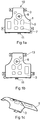
- Figures 1 shows (a) front, (b) back and (c) perspective views of a joined component 10.
- the joined component 10 includes a first body 1 and a second body 3, welded together along multiple weld lines 5. These weld lines are located both at edge portions of the component, and also at central portions of the joined component for forming internal pockets 7 in the component.
- the component may be formed of 6/4 titanium alloy, and may subsequently undergo superplastic forming into a final shape.
- the first and second bodies 1, 3 are, in this embodiment, skins, each being approximately 1 mm thick. Each body has datum features which include a central hole 9, and a cut out or slot 11 located on the bottom edge of the skin.
- the second body 3 also includes location tabs 13. These features match corresponding features in a holding fixture (described see below) to enable accurate location of the bodies within the holding fixture.
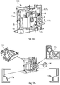
- Figure 2 shows (a) a perspective view of a holding fixture 100 in use, and (b) separate views of a number of parts of the fixture with arrows indicating the parts' locations within the fixture.
- the first and second bodies 1, 3 are correctly located in the fixture by matching of corresponding datum features of the bodies and the holding fixture. A central datum bung 14 is fitted to assist with this location.
- the bodies are then immobilised in the holding fixture 100 by a back clamp 15 and three front clamps 17a, b, c.
- the back clamp is rigidly attached to a base support 16. Two of the front clamps 17a, b are for clamping edge portions of the first and second bodies 1, 3, and one front clamp 17c is for clamping a central portion of the first and second bodies.
- the front clamps may be secured to the back clamp by toggle clamping, with toggles 19 applied to edge portions of each front clamp.
- Respective plenums (described below) are formed in the back and front clamps, the plenums being adapted to supply a shielding gas to back and front sides of the component along the weld lines 5.
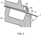
- Figure 3 shows, for example, a cross-section, transversely to a weld line 5 (the location of which is indicated by a dashed circle), through the back clamp 15 and one of the front 17 clamps of the holding fixture 100 in use.
- the first 1 and the second 3 body are immobilised between the clamps.
- a plenum 21 is formed in the front clamp as an elongate channel which runs parallel to, but laterally offset from, the path of the weld line 5,.
- Shielding gas is supplied through a slit 23 extending through the front clamp from the plenum 21 to an outlet 25 adjacent the front surface of the component at the weld line, such that a layer of shielding gas flows laterally over the weld line.
- a plenum 27 is also formed in the back clamp as a channel located directly behind, and opening onto, the weld line at the back surface of the component.
- the plenum 27 is conveniently formed as a U-shaped channel. This configuration enables provision of shielding gas to both surfaces of the component along the weld line, whist avoiding any obstruction by the front clamp of the laser beam on its way to the weld line.
- the holding fixture may be configured to immobilise the bodies such that a precisely controlled gap of e.g. 0.2 mm or less is formed between the bodies along the weld line. This can assist removal of vapours during the welding process.
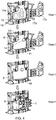
- Figure 4 shows a production process flow for a laser welding process which uses the holding fixture 100.
- the process flow shown is a two-stage clamping and welding process, with the first and second bodies welded together along multiple weld lines to form a joined component.
- Stage 1 the holding fixture 100 is attached to a machine bed (not shown) of a laser welding system by the base support 16, and all the front clamps 17a, b, c are opened.
- the back clamp 15 remains in a fixed position relative to the machine bed throughout the process.
- Stage 2 includes locating the first and second bodies 1, 3 to the holding fixture 100 by matching datum features 9, 11 and location tabs 13 of the first and second bodies with corresponding datum features on the holding fixture. This allows for accurate location of the skins to the holding fixture and can increase accuracy in the final built part.
- a central datum bung 14 is then fitted. The central datum bung acts as a preliminary hold until the front clamps are applied (Stage 3), and aids loading the first and second bodies in a vertical position.
- Stage 3 includes applying both left hand and right hand front clamps for immobilising the first and second bodies in the holding fixture.
- the left hand and right hand front clamps 17a, b are secured by toggle clamps 19 to provide even clamping forces around the component.
- the shielding gas supply is turned on, and argon (the shielding gas) is supplied to back and front sides of the component along a first weld line 5 around the perimeter of the component through plenums 21, 27 formed in respectively the front and back clamps.
- each of the front clamps 17a, b may have a respective plenum 21 each covering its half of the first weld line, while the rear clamp may have a single plenum covering the whole first weld line.
- the first and second skins 1, 3 are laser welded along the first weld line to form a joined component 10.
- the laser weld penetrates through the thickness of the component, from the front side to the back side of the component; but by supplying the argon to both sides of the weld from the plenums, it can be adequately protected from atmospheric gases.
- Performing the first weld before the third front clamp 17c is applied allows for un-interrupted welding along the first weld line, without obstruction by portions of the third clamp.
- Stage 4 includes applying the third front clamp 17c to a central portion of the joined component, and securing this with a toggle clamp 19.
- the shielding gas supply is turned on, and argon (the shielding gas) is supplied to back and front sides of the component along additional weld lines 5, through further plenums 21, 27 formed in the front clamp 17c and the back clamp.
- the first and second skins 1, 3 are laser welded along the respectively weld lines, e.g. to form internal pockets 7 in the joined component 10. Again the laser welds which are formed penetrate through the thickness of the component, from the front side to the back side of the component.
- the process such as that as shown in Figure 4 may be semi-automated. This can reduce human error and improve consistency of manufacturing to decrease the number of components having manufacturing errors. Additionally, semi-automation can reduce process dwells or other delays within the manufacturing process.
- the holding fixture may be used in combination with a laser welding system having a controller.
- the laser welding system controller may be conveniently adapted to control the supply of the shielding gas from the plenums in the back and front clamps. This control may be, for example, CNC controlled input/output switching of the supply of argon shielding gas to parts of the fixture, with automatic switch-off of shielding gas once it is no longer needed. This can improve shielding gas utilisation and reduce associated process costs.
- the process is easily adapted to suit a wide range of part geometries, in varying degrees of 3D orientation, by appropriate configuration of the holding fixture.
- the process is also easily adaptable to different weld types. Whilst Figure 4 shows lap welding, butt welding or fillet welding may equally be performed using the process. Where appropriate for the type of welding, filler wire or powder may be used during the welding process.
Landscapes
- Engineering & Computer Science (AREA)
- Physics & Mathematics (AREA)
- Optics & Photonics (AREA)
- Mechanical Engineering (AREA)
- Plasma & Fusion (AREA)
- Laser Beam Processing (AREA)
Applications Claiming Priority (1)
| Application Number | Priority Date | Filing Date | Title |
|---|---|---|---|
| GBGB1611190.8A GB201611190D0 (en) | 2016-06-28 | 2016-06-28 | Laser welding |
Publications (1)
| Publication Number | Publication Date |
|---|---|
| EP3263273A1 true EP3263273A1 (de) | 2018-01-03 |
Family
ID=56891713
Family Applications (1)
| Application Number | Title | Priority Date | Filing Date |
|---|---|---|---|
| EP17175276.9A Withdrawn EP3263273A1 (de) | 2016-06-28 | 2017-06-09 | Laserschweissen |
Country Status (3)
| Country | Link |
|---|---|
| US (1) | US10792763B2 (de) |
| EP (1) | EP3263273A1 (de) |
| GB (1) | GB201611190D0 (de) |
Cited By (1)
| Publication number | Priority date | Publication date | Assignee | Title |
|---|---|---|---|---|
| WO2020070195A1 (de) * | 2018-10-02 | 2020-04-09 | Trumpf Werkzeugmaschinen Gmbh + Co. Kg | Verfahren und spannvorrichtung zur herstellung einer schweissnaht an einer stossstelle zwischen zwei werkstücken mit einem laserstrahl |
Families Citing this family (1)
| Publication number | Priority date | Publication date | Assignee | Title |
|---|---|---|---|---|
| US11192205B2 (en) | 2019-05-19 | 2021-12-07 | Raytheon Technologies Corporation | Self-leveling container for laser welding |
Citations (5)
| Publication number | Priority date | Publication date | Assignee | Title |
|---|---|---|---|---|
| JPH10180472A (ja) * | 1996-12-25 | 1998-07-07 | Honda Motor Co Ltd | レーザ溶接装置 |
| KR20010027723A (ko) * | 1999-09-15 | 2001-04-06 | 신현준 | 판재 용접장치 |
| DE10261073A1 (de) * | 2002-12-24 | 2004-07-08 | Rolls-Royce Deutschland Ltd & Co Kg | Verfahren zum Fügen von Werkstücken aus Titanaluminid mittels eines Lötverfahrens |
| CN102935568B (zh) * | 2012-11-15 | 2015-01-07 | 西安交通大学 | 复杂空间形状钛合金薄壁件的激光焊接夹具与保护装置 |
| CN204818440U (zh) * | 2015-08-26 | 2015-12-02 | 航天海鹰(哈尔滨)钛业有限公司 | 一种钛合金精密成形件激光焊接气体保护装置 |
Family Cites Families (3)
| Publication number | Priority date | Publication date | Assignee | Title |
|---|---|---|---|---|
| US6153853A (en) * | 1996-12-25 | 2000-11-28 | Honda Giken Kogyo Kabushiki Kaisha | Laser beam welding apparatus |
| JP3954704B2 (ja) * | 1997-10-31 | 2007-08-08 | 株式会社コスメック | クランプ装置 |
| JP6218324B2 (ja) * | 2014-01-29 | 2017-10-25 | 株式会社タチエス | 車両用シートのシートフレーム成形方法、シートフレームおよび車両用シート |
-
2016
- 2016-06-28 GB GBGB1611190.8A patent/GB201611190D0/en not_active Ceased
-
2017
- 2017-06-09 EP EP17175276.9A patent/EP3263273A1/de not_active Withdrawn
- 2017-06-14 US US15/622,635 patent/US10792763B2/en not_active Expired - Fee Related
Patent Citations (5)
| Publication number | Priority date | Publication date | Assignee | Title |
|---|---|---|---|---|
| JPH10180472A (ja) * | 1996-12-25 | 1998-07-07 | Honda Motor Co Ltd | レーザ溶接装置 |
| KR20010027723A (ko) * | 1999-09-15 | 2001-04-06 | 신현준 | 판재 용접장치 |
| DE10261073A1 (de) * | 2002-12-24 | 2004-07-08 | Rolls-Royce Deutschland Ltd & Co Kg | Verfahren zum Fügen von Werkstücken aus Titanaluminid mittels eines Lötverfahrens |
| CN102935568B (zh) * | 2012-11-15 | 2015-01-07 | 西安交通大学 | 复杂空间形状钛合金薄壁件的激光焊接夹具与保护装置 |
| CN204818440U (zh) * | 2015-08-26 | 2015-12-02 | 航天海鹰(哈尔滨)钛业有限公司 | 一种钛合金精密成形件激光焊接气体保护装置 |
Non-Patent Citations (2)
| Title |
|---|
| "Handbuch Vorrichtungen", 31 December 1986, VIEWEG+TEUBNER VERLAG, ISBN: 978-3-322-89713-8, article HEINRICH MATUSZEWSKI: "Handbuch Vorrichtungen", pages: 47, XP055426394, DOI: 10.1007/978-3-322-89713-8 * |
| FLORIAN OEFFELE: "Remote-Laserstrahlschweißen mit brillanten Laserstrahlquellen", 31 December 2012 (2012-12-31), pages 75 - 79, XP055425937, Retrieved from the Internet <URL:https://mediatum.ub.tum.de/doc/1096019/1096019.pdf> [retrieved on 20171116] * |
Cited By (1)
| Publication number | Priority date | Publication date | Assignee | Title |
|---|---|---|---|---|
| WO2020070195A1 (de) * | 2018-10-02 | 2020-04-09 | Trumpf Werkzeugmaschinen Gmbh + Co. Kg | Verfahren und spannvorrichtung zur herstellung einer schweissnaht an einer stossstelle zwischen zwei werkstücken mit einem laserstrahl |
Also Published As
| Publication number | Publication date |
|---|---|
| US20170368639A1 (en) | 2017-12-28 |
| GB201611190D0 (en) | 2016-08-10 |
| US10792763B2 (en) | 2020-10-06 |
Similar Documents
| Publication | Publication Date | Title |
|---|---|---|
| US10792763B2 (en) | Laser welding | |
| US10562136B2 (en) | Method of forming a seat frame of a vehicle seat, seat frame for use in vehicle seat, and vehicle seat having the seat frame | |
| CN102281985B (zh) | 激光焊接方法 | |
| US20230001511A1 (en) | Method for butt welding at least two metal sheets | |
| US10486266B2 (en) | Laser metal deposition welding of automotive parts | |
| US20150314363A1 (en) | Method of forming a vehicle body structure from a pre-welded blank assembly | |
| US20200156170A1 (en) | Systems and methods for multi-path gouging | |
| EP2248624B1 (de) | Verfahren zum Strahlschweißen unter Verwendung belüfteter Zwischenlagen ; entsprechende Strahlschweißer und belüftete Zwischenlagen | |
| US10226839B2 (en) | Butt jointed closed section hollow structural element | |
| US9221121B2 (en) | Welding process for welding three elements using two angled energy beams | |
| US9981342B2 (en) | Method for assembling fuel supply pipe, and fuel supply pipe assembly device | |
| CN113333905B (zh) | 焊接的方法、装置和自动化焊接系统 | |
| KR20180020638A (ko) | 맞대기 용접용 레이저 아크 용접장치 | |
| US10046442B2 (en) | Vehicle body manufacturing apparatus | |
| JP6442863B2 (ja) | 溶接装置、溶接方法及び溶接部品加工装置 | |
| US20210162543A1 (en) | Method for trimming a bent tube | |
| JP5476083B2 (ja) | レーザ溶接方法 | |
| JPH0244627B2 (ja) | Denkionsuikitonokantainoseizohoho | |
| JP2024070882A (ja) | 溶接部の加工方法 | |
| JP6887254B2 (ja) | 外板溶接用治具を用いた溶接方法及び外板溶接用治具を用いた鉄道車両用外板の製造方法 | |
| CN220362094U (zh) | 一种刀具焊接装置及焊接设备 | |
| CN109382568A (zh) | 部件的制造方法 | |
| JP2681497B2 (ja) | アーク加工装置及び方法 | |
| JP2011147944A (ja) | レーザ・アーク複合溶接法 | |
| KR20130138459A (ko) | 플럭스가 자동 공급되는 티그 용접용 토치 및 이것을 이용한 용접방법 |
Legal Events
| Date | Code | Title | Description |
|---|---|---|---|
| PUAI | Public reference made under article 153(3) epc to a published international application that has entered the european phase |
Free format text: ORIGINAL CODE: 0009012 |
|
| STAA | Information on the status of an ep patent application or granted ep patent |
Free format text: STATUS: THE APPLICATION HAS BEEN PUBLISHED |
|
| AK | Designated contracting states |
Kind code of ref document: A1 Designated state(s): AL AT BE BG CH CY CZ DE DK EE ES FI FR GB GR HR HU IE IS IT LI LT LU LV MC MK MT NL NO PL PT RO RS SE SI SK SM TR |
|
| AX | Request for extension of the european patent |
Extension state: BA ME |
|
| STAA | Information on the status of an ep patent application or granted ep patent |
Free format text: STATUS: REQUEST FOR EXAMINATION WAS MADE |
|
| 17P | Request for examination filed |
Effective date: 20180703 |
|
| RBV | Designated contracting states (corrected) |
Designated state(s): AL AT BE BG CH CY CZ DE DK EE ES FI FR GB GR HR HU IE IS IT LI LT LU LV MC MK MT NL NO PL PT RO RS SE SI SK SM TR |
|
| RAP1 | Party data changed (applicant data changed or rights of an application transferred) |
Owner name: ROLLS-ROYCE PLC |
|
| STAA | Information on the status of an ep patent application or granted ep patent |
Free format text: STATUS: EXAMINATION IS IN PROGRESS |
|
| 17Q | First examination report despatched |
Effective date: 20210521 |
|
| STAA | Information on the status of an ep patent application or granted ep patent |
Free format text: STATUS: THE APPLICATION IS DEEMED TO BE WITHDRAWN |
|
| 18D | Application deemed to be withdrawn |
Effective date: 20211001 |