EP3263263B1 - Outil de fraisage avec des inserts de coupe remplaçables - Google Patents
Outil de fraisage avec des inserts de coupe remplaçables Download PDFInfo
- Publication number
- EP3263263B1 EP3263263B1 EP16177229.8A EP16177229A EP3263263B1 EP 3263263 B1 EP3263263 B1 EP 3263263B1 EP 16177229 A EP16177229 A EP 16177229A EP 3263263 B1 EP3263263 B1 EP 3263263B1
- Authority
- EP
- European Patent Office
- Prior art keywords
- cassettes
- hobbing tool
- recesses
- flange
- set forth
- Prior art date
- Legal status (The legal status is an assumption and is not a legal conclusion. Google has not performed a legal analysis and makes no representation as to the accuracy of the status listed.)
- Active
Links
- 230000013011 mating Effects 0.000 claims description 4
- 239000000463 material Substances 0.000 description 7
- 229910000997 High-speed steel Inorganic materials 0.000 description 3
- 239000007787 solid Substances 0.000 description 2
- 229910000831 Steel Inorganic materials 0.000 description 1
- 229910001315 Tool steel Inorganic materials 0.000 description 1
- 230000006978 adaptation Effects 0.000 description 1
- 230000003466 anti-cipated effect Effects 0.000 description 1
- 230000000712 assembly Effects 0.000 description 1
- 238000000429 assembly Methods 0.000 description 1
- 230000005540 biological transmission Effects 0.000 description 1
- 239000010959 steel Substances 0.000 description 1
Images


Classifications
-
- B—PERFORMING OPERATIONS; TRANSPORTING
- B23—MACHINE TOOLS; METAL-WORKING NOT OTHERWISE PROVIDED FOR
- B23F—MAKING GEARS OR TOOTHED RACKS
- B23F21/00—Tools specially adapted for use in machines for manufacturing gear teeth
- B23F21/12—Milling tools
- B23F21/16—Hobs
- B23F21/163—Hobs with inserted cutting elements
- B23F21/166—Hobs with inserted cutting elements in exchangeable arrangement
Definitions
- the present invention relates to hobbing tools and, more particularly, to hobbing tools with replaceable cutting inserts.
- a hobbing tool having the features of the preamble of independent claim 1, is known from document CN 103 071 864 A .
- hobs for generating gears below a certain size are generally solid tools made of high speed steel (HSS) or cemented carbide.
- HSS high speed steel
- Replaceable cutting inserts in hobbing tools are uncommon due to the low quality of those tools and their inability to guarantee fine quality of the gear.
- Indexable inserts are typically used in hobbing tools for roughing, pre-grinding, or pre-shaving operations.
- Other types of hobbing tools that have provided higher quality gears include inserted-blade cutter assemblies with removable blades, but these blades are made of solid cemented carbide or HSS and are different from each other. They do not provide an indexable insert solution and, therefore, wear on the cutting edges of the blade requires removal and sharpening and recoating or replacement of the blade.
- a hobbing tool comprises a hob body comprising at least one axially extending slot, at least one cassette removably disposed in the at least one slot, wherein the at least one cassette comprises at least one seating recess having at least a bottom abutment surface and two side abutment surfaces, and at least one cutting insert removably mounted in the at least one seating recess, at least one cutting insert having at least one bottom supporting surface and two side supporting surfaces that abut the bottom abutment surface and the two side abutment surfaces when the at least one cutting insert is received in the at least one seating recess.
- the hob body comprises a plurality of axially extending slots.
- the hobbing tool comprises a corresponding plurality of cassettes removably mounted in the plurality of axially extending slots. Each cassette of the plurality of cassettes is identical to every other cassette of the plurality of cassettes.
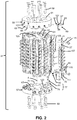
- a hobbing tool 21 is shown in FIG. 1 , and in exploded form in FIG. 2 .
- the hobbing tool 21 includes a hob body 23 comprising at least one axially extending slot 25 and, typically, a plurality of slots -- sixteen are shown in the hobbing tool in FIG. 2 .
- the hobbing tool 21 also includes at least one cassette 27 removably disposed in the at least one slot 25, with each cassette being disposed in a respective slot.
- Each slot 25 is ordinarily identical to every other slot and each cassette 27 is ordinarily identical to every other cassette, and the slots are compatible with the cassettes so that any cassette can be received in any slot.
- Each cassette 27 comprises at least one seating recess 29 having, as seen, for example, in FIG. 5 at least a bottom abutment surface 31 and two side abutment surfaces 33 and 35.
- a cutting insert 37 is removably mounted in each seating recess 29.
- the cutting insert 37 has at least one bottom supporting surface 39 and two side supporting surfaces 41 and 43 that abut the bottom abutment surface 31 and the two side abutment surfaces 33 and 35 when the cutting insert is received in the at least one seating recess.
- the side abutment surfaces 33 and 35 are typically generally flat and define an angle ⁇ between them.
- the side supporting surfaces 41 and 43 are also typically generally flat and define an angle of ⁇ or slightly greater than ⁇ between them to ensure that each side supporting surface contacts a corresponding side abutment surface at all times.
- the cutting insert 37 is clamped in the seating recess 29 by a suitable clamping means, such as a screw 45 that extends through a central through hole 47 in the cutting insert and that has external threads that mate with internal threads in a hole 49 in the cassette 27.
- suitable clamping means include but are not limited to clamps having arms that contact a top surface of the insert to clamp it in place.
- the illustrated cutting insert 37 has four sides of equal length and is indexable to two positions so that two different cutting edges 51 can be disposed in a working position.
- the illustrated cutting insert 37 is single sided, however, it is also possible to provide double-sided inserts in which each side can function as a bottom supporting surface 39 when it abuts the bottom abutment surface 31 of the seating recess 29, while the opposite side can function as a top chip surface 53.
- the illustrated cutting insert has two cutting edges 51 associated with the top chip surface 53.
- the insert has four surfaces that are each associated with respective ones of the four sides of equal length.
- the cutting insert 37 is indexable so that, when two of the four surfaces associated with respective ones of the four sides of equal length abut either of the two side abutment surfaces 33 and 35, those two surfaces function as the side supporting surfaces 41 and 43.
- the illustrated cutting insert 37 is indexable to two positions, however, other cutting inserts may not be indexable, or may be indexable to more positions than the illustrated cutting insert, such as by providing a double-sided cutting insert or by providing a cutting insert with more than four sides.
- the hobbing tool 21 comprises a top flange 55 and a bottom flange 57 attached to the hob body 23, typically by bolts 59 that extend through holes 61 in the flanges and that have external threads that mate with internal threads of holes 63 in the hob body 23.
- the holes 61 in the flanges 55 and 57 and the holes 63 in the hob body 23 typically but not necessarily extend parallel to the axis A of the hobbing tool 21.
- the top flange 55 has a bottom end 65 facing the hob body 23 and the bottom flange 57 has a top end 67 facing the hob body 23.
- the bottom end 65 of the top flange 55 and the top end 67 of the bottom flange 57 each comprise top recesses 69 and bottom recesses 71 equal in number to the number of cassettes 27 for receiving top ends 73 and bottom ends 75, respectively, of respective ones of the of cassettes.
- Each recess 69 and 71 of the plurality of recesses in one or, as illustrated, both of the top flange 55 and the bottom flange 57 has a different axial depth than any other recess of the plurality of recesses in the one of the top flange and the bottom flange, i.e., they are "stepped".
- the changes in depth of the recesses can result in the cutting inserts 37 on cassettes 27 mounted on the hobbing tool 21 forming a helix. It is not, however, necessary that the cassettes 27 and inserts 37 form a helix. In addition to forming a single helix as shown in FIGS.
- the hobbing tool 21 can comprise an anvil arrangement 77, seen in FIGS. 4A and 4C , disposed in each of the plurality of bottom recesses 71.
- the anvil arrangement 77 can prevent direct contact between the cassettes 27 and the axial bottoms of the bottom recesses 71 to reduce the possibility of damage to the recesses, and can also facilitate minor adjustment of the positions of the cassettes relative to one another.
- the anvil arrangement 77 can comprise an anvil 79 and an anvil screw 81 disposed in each of the plurality of bottom recesses 71.
- the anvil screw 81 can mate with internal threads in holes 83 in the bottom flange 57.
- the anvil 79 can comprise an abutment surface 85 for abutting a bottom end 75 of a respective one of the plurality of cassettes 27.
- the position of each cassette 27 can be adjusted by providing an anvil 79 of different size, by providing shims (not shown) between the anvil 79 and the bottom recesses 71, or by other means such as by providing a differential screw arrangement including internal threads in a through hole 87 in the anvil for mating with corresponding external threads on the anvil screw 81.
- the holes 83 in the bottom flange 57 are non-perpendicular to an axis A ( FIG. 2 ) of the hobbing tool and may be parallel to the axis.
- the internal threads in the holes 83 in the bottom flange 57 and the external threads on the anvil screw 81 that mate with the internal threads in the holes in the bottom flange 57 can have a different pitch or different thread hand than the internal threads in the through hole 87 of the anvil 79 that mate with the external threads on the anvil screw for mating with the internal threads in the through hole in the anvil to facilitate adjustments of the position of the abutment surface 85.
- the head of the anvil screw 81 can be sealed, such as with wax (not shown) to prevent further movement.
- the hobbing tool 21 can also comprise a wedge arrangement 89, seen in FIGS. 4A and 4C , disposed in each of the plurality of top recesses 69.
- the wedge arrangement 89 can facilitate securely clamping the cassettes 27 in the slots 25 in the hob body 23 and between the top and bottom flanges 55 and 57.
- the wedge arrangement 89 can comprise a wedge 91 and a wedge screw 93 disposed in each of the plurality of top recesses 69.
- the wedge screw 93 can mate with internal threads in holes 95 in the top flange 55 and can extend through a hole 97 in the wedge 91.
- the hole 97 in the wedge may be internally threaded and mate with external threads on the wedge screw 93 that have a different pitch or different thread hand than the threads that mate with the internal threads in the holes 95 so that the wedge arrangement forms a differential screw arrangement.
- An abutment surface 99 of the wedge 91 abuts a top end 73 of a respective one of the plurality of cassettes 27 and a wedge surface 101 of the wedge abuts a wedge surface 103 of a respective top recess 69.
- the holes 95 in the top flange 55 are ordinarily perpendicular to or non-parallel with the axis A of the hobbing tool 21.
- worm screws 105 can be provided in internally threaded holes 107 in the cassettes 27 to assist in securing the cassettes in the slots 25 in the hob body 23.
- the holes 107 in the cassettes 27 are positioned so that, when the cassettes are disposed in slots 25 in the hob body 23, one end 109 of a hole 107 is exposed and the other end 111 is adjacent a wall 113 of the slot.
- the worm screws 105 will typically have an end with a hex or other non-circular external or internal shape to be turned by a structure such as an Allen wrench. As the worm screws 105 are tightened so that they extend out of the end of holes 107 adjacent the walls of the slots 25, the worm screws will assist in clamping the cassettes 27 to assist in resisting tangential forces on the cassettes.
- each cassette 27 of the plurality of cassettes can be removably mounted in a respective one of the plurality of axially extending slots 25 by screws 115 that extend through axially elongated slots 117 in tops and bottoms of each cassette and that mate with internal threads in holes 119 in the hob body 23. Heads of the screws 115 clamp against surfaces of the cassette adjacent the axially elongated slots 117 to clamp the cassettes 27 relative to the hob body 23.
- While position of the cassettes 27 relative to the hob body 23 can be adjusted by positioning the cassettes in a desired position relative to the hob body and then tightening the screws 115, the screws are particularly useful for facilitating ensuring a secure attachment of the cassettes 27 to the hob body 23, while the anvil arrangement 77 and the wedge arrangement 89 facilitate small adjustments in the position of the cassettes prior to tightening of the screws 115 (typically during assembly of the hob).
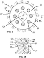
- the screws 115 typically extend in a generally radial direction relative to the axis A of the hobbing tool 21 and provide a clamping force that is directed in a generally radial direction, while the worm screws 105, axes of which bisect the hobbing tool as seen in FIG. 4B , extend in a more tangential direction relative to an exterior surface of the hobbing tool and provide a clamping force in a generally tangential direction.
- a hobbing tool 21 will be partially pre-assembled with anvil arrangements 77 attached in the bottom flange 57 and with the top and bottom flanges 55 and 57 attached to the hob body 23.
- Anvil arrangements 77 may be attached in the bottom flange 57 before or after attachment of the bottom flange to the hob body 23.
- the anvil arrangements 77 and top and bottom flanges 55 and 57 will ordinarily not be adjusted during normal use and may be done by a manufacturer, which can facilitate erasing axial pitch deviations between cassettes due to improper positioning of cassettes by an end user.
- Cutting inserts 37 are attached to cassettes 27 in seating recesses 29 of the cassettes with the screws 45.
- the cassettes are then positioned in slots 25 in the hobbing tool 21 so that bottom ends 75 of the cassettes abut against the abutment surfaces 85 of the anvils 79 of the anvil arrangements 77.
- the cutting inserts 37 might be attached to the cassettes 27 after the cassettes are in the slots 25 in some embodiments of the present invention, it will be seen that, in the illustrated embodiment, the screws 45 may be wholly or partially obscured by the hob body 23 when the cassettes are in the slots.
- the cassettes 27 are then loosely secured in the slots 25 by the screws 115 that extend through the axially elongated slots 117 into the internally threaded holes 119 in the hob body 23.
- the cassettes 27 are then clamped in an axial direction between the anvil arrangement 77 and the wedge arrangement 89 by wedging the wedges 91 between the top ends 73 of the cassettes and the bottom ends of the top recesses 69 of the top flange 55.
- the cassettes 27 are then clamped in a generally tangential direction by tightening the worm screws 105 so that they extend out of the ends 111 of the holes 107 in the cassettes and abut against the walls 113 of the slots 25.
- cassettes 27 are fully secured in the slots 25 by fully tightening the screws 115 that extend through the axially elongated slots 117 into the internally threaded holes 119 in the hob body 23.
- Cutting inserts 37 can be indexed according to a schedule or upon observation of damage to a particular insert.
- the steps for removing the cassette 27 to permit indexing of cutting inserts 37 will ordinarily be the same as the steps for attaching the cassette, performed in reverse order.
- the cutting inserts 37 can be made of any suitable material, such as a coated cemented carbide material.
- the hob body 23, the cassettes 27, and the top and bottom flanges 55 and 57 are made of suitable materials, such as tool steel or quenched and tempered steel.
- the term 'small' module hob may here mean a hob with a working diameter that is 5 to 8 times a longest length of the cutting insert 37.
- One or more calibration pins can be provided to extend through one or more calibration holes 121 ( FIG. 2 ) in the hob body 23 to be received in corresponding calibration holes 123 ( FIG. 2 ) extending part of the way through the bottom flange 57 and calibration holes (not shown) extending part of the way through the top flange 55. In this way, correct orientation of the top flange 55, the bottom flange 57, and the hob body 23 can be facilitated during assembly and in the event of disassembly and reassembly and the calibration pins need not be exposed except after disassembly.
- Torque transmission from a drive shaft will typically be via a non-circular central opening 125 in the hob body 23 as seen, for example, in FIG. 3 .
- the drive shaft need not contact the top and bottom flanges 55 and 57.
- the single block design of the cassettes 27 facilitates providing a precise pitch between adjacent cutting inserts 37 because each cassette is identical to every other cassette. Repeatability of proper locating of cutting inserts relative to their insert pockets is facilitated by provision of the bottom and angled supporting surfaces 39, 41, and 43 of the cutting inserts, and the bottom and angled abutment surfaces 31, 33, and 35 of the seating recesses 29.
Landscapes
- Engineering & Computer Science (AREA)
- Mechanical Engineering (AREA)
- Gear Processing (AREA)
Claims (13)
- Outil à tailler à la fraise-mère (21) comprenant :un corps de fraise-mère (23) comprenant au moins une fente (25) s'étendant axialement ;au moins une cassette (27) disposée de manière amovible dans la au moins une fente (25),la au moins une cassette (27) comprenant au moins un logement de réception (29) ayant au moins une surface de butée inférieure (31) et deux surfaces de butée latérales (33, 35), au moins une plaquette de coupe (37) étant montée de manière amovible dans le au moins un logement de réception (29), la au moins une plaquette de coupe (37) ayant au moins une surface de support inférieure (39) et deux surfaces de support latérales (41, 43) qui viennent en butée contre la surface de butée inférieure (31) ainsi que les deux surfaces de butée latérales (33, 35) lorsque la au moins une plaquette de coupe (37) est reçue dans le au moins un logement de réception (29),dans lequel le corps de fraise-mère (23) comprend une pluralité de fentes (25) s'étendant axialement et l'outil à tailler à la fraise-mère (21) comprend une pluralité correspondante de cassettes (27) montées de manière amovible dans la pluralité de fentes (25) s'étendant axialement, caractérisé en ce que chaque cassette (27) parmi la pluralité de cassettes (27) est identique à chaque autre cassette (27) de la pluralité de cassettes (27).
- Outil à tailler à la fraise-mère (21) selon la revendication 1, dans lequel l'outil à tailler à la fraise-mère (21) comprend un flasque supérieure (55) et un flasque inférieure (57) fixés au corps de fraise-mère (23).
- Outil à tailler à la fraise-mère (21) selon la revendication 2, dans lequel l'outil à tailler à la fraise-mère (21) comprend une pluralité de cassettes (27), le corps de fraise-mère (23) comprend une pluralité correspondante de fentes (25), le flasque supérieure (55) comporte une extrémité inférieure (65) tournée vers le corps de fraise-mère (23) et le flasque inférieure (67) présente une extrémité supérieure (67) tournée vers le corps de fraise-mère (23), et l'extrémité inférieure (65) du flasque supérieur (55)) et l'extrémité supérieure (67) du flasque inférieure (57) comprennent chacune une pluralité correspondante d'évidements supérieurs (69) et d'évidements inférieurs (71) destinés à recevoir respectivement des extrémités supérieures et inférieures (73 et 75) respectives de la pluralité de cassettes (27).
- Outil à tailler à la fraise-mère (21) selon la revendication 3, dans lequel chaque évidement d'au moins un parmi la pluralité d'évidements supérieurs (69) dans le flasque supérieure (55) et la pluralité d'évidements inférieurs (71) dans le flasque inférieure (57) a une profondeur axiale différente de celle de tout autre évidement de le au moins un parmi la pluralité d'évidements supérieurs (69) dans le flasque supérieure (55) et la pluralité d'évidements inférieurs (71) dans le flasque inférieure (57).
- Outil à tailler à la fraise-mère (21) selon la revendication 4, dans lequel chaque évidement de la pluralité d'évidements (71) dans le flasque inférieure (57) a une profondeur axiale différente de celle de tout autre évidement de la pluralité d'évidements (71) dans le flasque inférieure (57).
- Outil à tailler à la fraise-mère (21) selon l'une quelconque des revendications 4 à 5, dans lequel chaque évidement de la pluralité d'évidements (69) dans le flasque supérieur (55) a une profondeur axiale différente de celle de tout autre évidement de la pluralité d'évidements (69) dans le flasque supérieure (55).
- Outil à tailler à la fraise-mère (21) selon l'une quelconque des revendications 3 à 6, dans lequel l'outil à tailler à la fraise-mère (21) comprend un agencement formant enclume (77) comprenant une enclume (79) et une vis d'enclume (81) disposée dans chacune de la pluralité d'évidements inférieures (71), la vis d'enclume (81) s'accouplant avec des filets internes dans des orifices (83) dans le flasque inférieure (57), une surface de butée (85) de chaque enclume (79) venant en butée contre une extrémité inférieure (75) d'une cassette respective parmi la pluralité de cassettes (27).
- Outil à tailler à la fraise-mère (21) selon l'une quelconque des revendications 3 à 7, dans lequel l'outil à tailler à la fraise-mère (21) comprend un agencement formant coin (89) comprenant un coin (91) et une vis associée au coin (93) disposée dans chacun de la pluralité de renfoncements supérieurs (69), la vis associée au coin (93) s'accouplant avec des filets internes dans des orifices (95) dans le flasque supérieure (55) et avec des filets internes dans des orifices (97) dans le coin (91), une surface de butée (99) du coin (91) venant en butée contre une extrémité supérieure (73) de l'une respective parmi la pluralité de cassettes (27) et une surface en coin (101) du coin (91) venant en butée contre une surface en coin (103) d'un évidement supérieur respectif (69).
- Outil à tailler à la fraise-mère (21) selon l'une quelconque des revendications 3 à 8, dans lequel chaque cassette (27) de la pluralité de cassettes (27) est montée de manière amovible dans respectivement l'une de la pluralité de fentes (25) s'étendant axialement au moyen de vis (115) qui s'étendent à travers des fentes allongées axialement (117) dans les sommets et les fonds de chaque cassette (27) et qui s'accouplent avec des filets internes dans des orifices (119) dans le corps de fraise-mère (23).
- Outil à tailler à la fraise-mère (21) selon l'une quelconque des revendications 1 à 9, dans lequel la pluralité de cassettes (27) sont montées par rapport au corps de fraise-mère (23) de sorte que des plaquettes de coupe (37) sur la pluralité de cassettes (27) forment une hélice.
- Outil à tailler à la fraise-mère (21) selon l'une quelconque des revendications 1 à 10, dans lequel chaque cassette (27) de la pluralité de cassettes (27) comprend une pluralité de logements de réception (29) et dans lequel une pluralité correspondante de plaquettes de coupe (37) est montée de manière amovible dans chacun de la pluralité de logements de réception (29).
- Outil à tailler à la fraise-mère (21) selon l'une quelconque des revendications 1 à 11, dans lequel la au moins une plaquette de coupe (37) présente quatre côtés (41, 43) de même longueur.
- Outil à tailler à la fraise-mère (21) selon l'une quelconque des revendications 1 à 12, dans lequel la au moins une plaquette de coupe (37) peut être indexée sur quatre positions.
Priority Applications (4)
| Application Number | Priority Date | Filing Date | Title |
|---|---|---|---|
| EP16177229.8A EP3263263B1 (fr) | 2016-06-30 | 2016-06-30 | Outil de fraisage avec des inserts de coupe remplaçables |
| US16/311,446 US10654119B2 (en) | 2016-06-30 | 2017-04-07 | Hobbing tool with replaceable cutting inserts |
| PCT/EP2017/058441 WO2018001585A1 (fr) | 2016-06-30 | 2017-04-07 | Outil de fraisage doté de plaquettes de coupe remplaçables |
| CN201780034673.0A CN109311108B (zh) | 2016-06-30 | 2017-04-07 | 具有可更换的切削刀片的滚齿刀具 |
Applications Claiming Priority (1)
| Application Number | Priority Date | Filing Date | Title |
|---|---|---|---|
| EP16177229.8A EP3263263B1 (fr) | 2016-06-30 | 2016-06-30 | Outil de fraisage avec des inserts de coupe remplaçables |
Publications (2)
| Publication Number | Publication Date |
|---|---|
| EP3263263A1 EP3263263A1 (fr) | 2018-01-03 |
| EP3263263B1 true EP3263263B1 (fr) | 2019-01-23 |
Family
ID=56368834
Family Applications (1)
| Application Number | Title | Priority Date | Filing Date |
|---|---|---|---|
| EP16177229.8A Active EP3263263B1 (fr) | 2016-06-30 | 2016-06-30 | Outil de fraisage avec des inserts de coupe remplaçables |
Country Status (4)
| Country | Link |
|---|---|
| US (1) | US10654119B2 (fr) |
| EP (1) | EP3263263B1 (fr) |
| CN (1) | CN109311108B (fr) |
| WO (1) | WO2018001585A1 (fr) |
Families Citing this family (1)
| Publication number | Priority date | Publication date | Assignee | Title |
|---|---|---|---|---|
| CN114799366B (zh) * | 2022-03-09 | 2024-07-19 | 哈尔滨诶埃科技有限公司 | 一种镶嵌式高阶精度全转位内冷齿轮滚刀 |
Family Cites Families (14)
| Publication number | Priority date | Publication date | Assignee | Title |
|---|---|---|---|---|
| DE147635C (fr) | ||||
| DE191524C (fr) * | ||||
| AT301300B (de) * | 1969-08-13 | 1972-08-25 | Plansee Metallwerk | Abwälzfräser |
| DE2159336A1 (de) * | 1970-12-16 | 1972-07-06 | Dijet Kogyo K K | Fraeser |
| JPS522388U (fr) * | 1975-06-24 | 1977-01-08 | ||
| DD147635A1 (de) * | 1979-12-06 | 1981-04-15 | Manfred Seifert | Waelzfraeser mit schneidelementen in eingesetzten schneidentraegern |
| DE3241696C1 (de) * | 1982-11-11 | 1984-06-07 | Wälztechnik Saacke-Zorn GmbH & Co KG, 7530 Pforzheim | Hochleistungs-Waelzfraeser |
| DE3535079A1 (de) * | 1985-10-02 | 1987-04-09 | Bernhard Ranker | Hochleistungs-waelzfraeser |
| JP2559034B2 (ja) * | 1986-12-17 | 1996-11-27 | 株式会社小松製作所 | スロアウエイ式ホブの製造方法 |
| JPH01228718A (ja) * | 1988-03-10 | 1989-09-12 | Toyota Motor Corp | 可変アデンダムホブ |
| SE531858C2 (sv) * | 2007-12-21 | 2009-08-25 | Sandvik Intellectual Property | Fräsverktyg för spånavskiljande bearbetning, samt skärkropp och grundkropp härför |
| CN103071864B (zh) * | 2013-01-29 | 2015-02-04 | 福州大学 | 平面二次包络环面蜗杆传动镶齿可转位蜗轮滚刀 |
| DE202015004072U1 (de) * | 2015-06-11 | 2016-09-14 | Johne & Co. Präzisionswerkzeuge GmbH | Wälzfräszähne-Halter, Wälzfräswerkzeug und Bausatz zum Zusammenbauen eines Wälzfräswerkzeugs |
| JP6035697B1 (ja) * | 2015-12-24 | 2016-11-30 | 株式会社タンガロイ | 切削インサートおよび切削工具 |
-
2016
- 2016-06-30 EP EP16177229.8A patent/EP3263263B1/fr active Active
-
2017
- 2017-04-07 CN CN201780034673.0A patent/CN109311108B/zh active Active
- 2017-04-07 WO PCT/EP2017/058441 patent/WO2018001585A1/fr active Application Filing
- 2017-04-07 US US16/311,446 patent/US10654119B2/en active Active
Non-Patent Citations (1)
| Title |
|---|
| None * |
Also Published As
| Publication number | Publication date |
|---|---|
| US10654119B2 (en) | 2020-05-19 |
| EP3263263A1 (fr) | 2018-01-03 |
| US20190232405A1 (en) | 2019-08-01 |
| CN109311108A (zh) | 2019-02-05 |
| CN109311108B (zh) | 2021-06-15 |
| WO2018001585A1 (fr) | 2018-01-04 |
Similar Documents
| Publication | Publication Date | Title |
|---|---|---|
| US8961075B2 (en) | Milling tool as well as set of milling inserts of a milling tool | |
| EP1868779B1 (fr) | Fraise en bout orbitale | |
| EP2487001B1 (fr) | Insert de découpe pour outil de fraisage | |
| US8926232B2 (en) | Milling tool as well as segment therefor | |
| US8696258B2 (en) | Cutting tool and cartridge for the same | |
| US6280122B1 (en) | Milling tool with precisely positionable inserts | |
| EP1890833A1 (fr) | Plaquette et outil de fraisage, et plaque de calage destinee a ces outils | |
| EP2285518B1 (fr) | Outil de coupe avec insert de coupe ayant de multiples arêtes de coupe, et insert de coupe pour celui-ci | |
| US20190168315A1 (en) | Rotary tool having exchangeable cutting inserts and tool main-body set for a rotary tool | |
| US7059810B2 (en) | Gear hobbing cutter system | |
| EP3041633B1 (fr) | Outil de coupe périphérique utilisant des lames de type bâton | |
| EP1810768B1 (fr) | Outil de coupe rotatif avec mécanisme de réglage du jeu de la lame de fraise | |
| EP2896745A1 (fr) | Outil de fraisage | |
| KR20150054679A (ko) | 기어 호빙 공구, 기어 호빙 공구용 인서트 홀더, 칩 제거 유닛, 및 인서트 키트 | |
| JP2013056396A (ja) | インデキサブル式ねじ切りフライス | |
| EP3263263B1 (fr) | Outil de fraisage avec des inserts de coupe remplaçables | |
| US20080170915A1 (en) | Face hobbing or gear cutting head for cutting gears, such as spiral, bevel, spiral-bevel, and hypoid gears | |
| CN106457433B (zh) | 组合式滚刀 | |
| CN114799366B (zh) | 一种镶嵌式高阶精度全转位内冷齿轮滚刀 | |
| RU70473U1 (ru) | Протяжка для обработки эвольвентных шлицев | |
| JPH0372407B2 (fr) |
Legal Events
| Date | Code | Title | Description |
|---|---|---|---|
| PUAI | Public reference made under article 153(3) epc to a published international application that has entered the european phase |
Free format text: ORIGINAL CODE: 0009012 |
|
| STAA | Information on the status of an ep patent application or granted ep patent |
Free format text: STATUS: THE APPLICATION HAS BEEN PUBLISHED |
|
| AK | Designated contracting states |
Kind code of ref document: A1 Designated state(s): AL AT BE BG CH CY CZ DE DK EE ES FI FR GB GR HR HU IE IS IT LI LT LU LV MC MK MT NL NO PL PT RO RS SE SI SK SM TR |
|
| AX | Request for extension of the european patent |
Extension state: BA ME |
|
| STAA | Information on the status of an ep patent application or granted ep patent |
Free format text: STATUS: REQUEST FOR EXAMINATION WAS MADE |
|
| 17P | Request for examination filed |
Effective date: 20180703 |
|
| RBV | Designated contracting states (corrected) |
Designated state(s): AL AT BE BG CH CY CZ DE DK EE ES FI FR GB GR HR HU IE IS IT LI LT LU LV MC MK MT NL NO PL PT RO RS SE SI SK SM TR |
|
| GRAP | Despatch of communication of intention to grant a patent |
Free format text: ORIGINAL CODE: EPIDOSNIGR1 |
|
| STAA | Information on the status of an ep patent application or granted ep patent |
Free format text: STATUS: GRANT OF PATENT IS INTENDED |
|
| INTG | Intention to grant announced |
Effective date: 20180928 |
|
| RIN1 | Information on inventor provided before grant (corrected) |
Inventor name: CONSONNI, ANDREA |
|
| GRAS | Grant fee paid |
Free format text: ORIGINAL CODE: EPIDOSNIGR3 |
|
| GRAA | (expected) grant |
Free format text: ORIGINAL CODE: 0009210 |
|
| STAA | Information on the status of an ep patent application or granted ep patent |
Free format text: STATUS: THE PATENT HAS BEEN GRANTED |
|
| AK | Designated contracting states |
Kind code of ref document: B1 Designated state(s): AL AT BE BG CH CY CZ DE DK EE ES FI FR GB GR HR HU IE IS IT LI LT LU LV MC MK MT NL NO PL PT RO RS SE SI SK SM TR |
|
| REG | Reference to a national code |
Ref country code: GB Ref legal event code: FG4D |
|
| REG | Reference to a national code |
Ref country code: CH Ref legal event code: EP |
|
| REG | Reference to a national code |
Ref country code: AT Ref legal event code: REF Ref document number: 1091061 Country of ref document: AT Kind code of ref document: T Effective date: 20190215 |
|
| REG | Reference to a national code |
Ref country code: IE Ref legal event code: FG4D |
|
| REG | Reference to a national code |
Ref country code: DE Ref legal event code: R096 Ref document number: 602016009377 Country of ref document: DE |
|
| REG | Reference to a national code |
Ref country code: NL Ref legal event code: MP Effective date: 20190123 |
|
| PG25 | Lapsed in a contracting state [announced via postgrant information from national office to epo] |
Ref country code: NL Free format text: LAPSE BECAUSE OF FAILURE TO SUBMIT A TRANSLATION OF THE DESCRIPTION OR TO PAY THE FEE WITHIN THE PRESCRIBED TIME-LIMIT Effective date: 20190123 |
|
| PG25 | Lapsed in a contracting state [announced via postgrant information from national office to epo] |
Ref country code: LT Free format text: LAPSE BECAUSE OF FAILURE TO SUBMIT A TRANSLATION OF THE DESCRIPTION OR TO PAY THE FEE WITHIN THE PRESCRIBED TIME-LIMIT Effective date: 20190123 Ref country code: PL Free format text: LAPSE BECAUSE OF FAILURE TO SUBMIT A TRANSLATION OF THE DESCRIPTION OR TO PAY THE FEE WITHIN THE PRESCRIBED TIME-LIMIT Effective date: 20190123 Ref country code: SE Free format text: LAPSE BECAUSE OF FAILURE TO SUBMIT A TRANSLATION OF THE DESCRIPTION OR TO PAY THE FEE WITHIN THE PRESCRIBED TIME-LIMIT Effective date: 20190123 Ref country code: NO Free format text: LAPSE BECAUSE OF FAILURE TO SUBMIT A TRANSLATION OF THE DESCRIPTION OR TO PAY THE FEE WITHIN THE PRESCRIBED TIME-LIMIT Effective date: 20190423 Ref country code: FI Free format text: LAPSE BECAUSE OF FAILURE TO SUBMIT A TRANSLATION OF THE DESCRIPTION OR TO PAY THE FEE WITHIN THE PRESCRIBED TIME-LIMIT Effective date: 20190123 Ref country code: PT Free format text: LAPSE BECAUSE OF FAILURE TO SUBMIT A TRANSLATION OF THE DESCRIPTION OR TO PAY THE FEE WITHIN THE PRESCRIBED TIME-LIMIT Effective date: 20190523 Ref country code: ES Free format text: LAPSE BECAUSE OF FAILURE TO SUBMIT A TRANSLATION OF THE DESCRIPTION OR TO PAY THE FEE WITHIN THE PRESCRIBED TIME-LIMIT Effective date: 20190123 |
|
| REG | Reference to a national code |
Ref country code: AT Ref legal event code: MK05 Ref document number: 1091061 Country of ref document: AT Kind code of ref document: T Effective date: 20190123 |
|
| PG25 | Lapsed in a contracting state [announced via postgrant information from national office to epo] |
Ref country code: IS Free format text: LAPSE BECAUSE OF FAILURE TO SUBMIT A TRANSLATION OF THE DESCRIPTION OR TO PAY THE FEE WITHIN THE PRESCRIBED TIME-LIMIT Effective date: 20190523 Ref country code: LV Free format text: LAPSE BECAUSE OF FAILURE TO SUBMIT A TRANSLATION OF THE DESCRIPTION OR TO PAY THE FEE WITHIN THE PRESCRIBED TIME-LIMIT Effective date: 20190123 Ref country code: HR Free format text: LAPSE BECAUSE OF FAILURE TO SUBMIT A TRANSLATION OF THE DESCRIPTION OR TO PAY THE FEE WITHIN THE PRESCRIBED TIME-LIMIT Effective date: 20190123 Ref country code: GR Free format text: LAPSE BECAUSE OF FAILURE TO SUBMIT A TRANSLATION OF THE DESCRIPTION OR TO PAY THE FEE WITHIN THE PRESCRIBED TIME-LIMIT Effective date: 20190424 Ref country code: RS Free format text: LAPSE BECAUSE OF FAILURE TO SUBMIT A TRANSLATION OF THE DESCRIPTION OR TO PAY THE FEE WITHIN THE PRESCRIBED TIME-LIMIT Effective date: 20190123 Ref country code: BG Free format text: LAPSE BECAUSE OF FAILURE TO SUBMIT A TRANSLATION OF THE DESCRIPTION OR TO PAY THE FEE WITHIN THE PRESCRIBED TIME-LIMIT Effective date: 20190423 |
|
| REG | Reference to a national code |
Ref country code: DE Ref legal event code: R097 Ref document number: 602016009377 Country of ref document: DE |
|
| PG25 | Lapsed in a contracting state [announced via postgrant information from national office to epo] |
Ref country code: AL Free format text: LAPSE BECAUSE OF FAILURE TO SUBMIT A TRANSLATION OF THE DESCRIPTION OR TO PAY THE FEE WITHIN THE PRESCRIBED TIME-LIMIT Effective date: 20190123 Ref country code: DK Free format text: LAPSE BECAUSE OF FAILURE TO SUBMIT A TRANSLATION OF THE DESCRIPTION OR TO PAY THE FEE WITHIN THE PRESCRIBED TIME-LIMIT Effective date: 20190123 Ref country code: EE Free format text: LAPSE BECAUSE OF FAILURE TO SUBMIT A TRANSLATION OF THE DESCRIPTION OR TO PAY THE FEE WITHIN THE PRESCRIBED TIME-LIMIT Effective date: 20190123 Ref country code: CZ Free format text: LAPSE BECAUSE OF FAILURE TO SUBMIT A TRANSLATION OF THE DESCRIPTION OR TO PAY THE FEE WITHIN THE PRESCRIBED TIME-LIMIT Effective date: 20190123 Ref country code: RO Free format text: LAPSE BECAUSE OF FAILURE TO SUBMIT A TRANSLATION OF THE DESCRIPTION OR TO PAY THE FEE WITHIN THE PRESCRIBED TIME-LIMIT Effective date: 20190123 Ref country code: SK Free format text: LAPSE BECAUSE OF FAILURE TO SUBMIT A TRANSLATION OF THE DESCRIPTION OR TO PAY THE FEE WITHIN THE PRESCRIBED TIME-LIMIT Effective date: 20190123 |
|
| PG25 | Lapsed in a contracting state [announced via postgrant information from national office to epo] |
Ref country code: SM Free format text: LAPSE BECAUSE OF FAILURE TO SUBMIT A TRANSLATION OF THE DESCRIPTION OR TO PAY THE FEE WITHIN THE PRESCRIBED TIME-LIMIT Effective date: 20190123 |
|
| PLBE | No opposition filed within time limit |
Free format text: ORIGINAL CODE: 0009261 |
|
| STAA | Information on the status of an ep patent application or granted ep patent |
Free format text: STATUS: NO OPPOSITION FILED WITHIN TIME LIMIT |
|
| PG25 | Lapsed in a contracting state [announced via postgrant information from national office to epo] |
Ref country code: AT Free format text: LAPSE BECAUSE OF FAILURE TO SUBMIT A TRANSLATION OF THE DESCRIPTION OR TO PAY THE FEE WITHIN THE PRESCRIBED TIME-LIMIT Effective date: 20190123 |
|
| 26N | No opposition filed |
Effective date: 20191024 |
|
| PG25 | Lapsed in a contracting state [announced via postgrant information from national office to epo] |
Ref country code: MC Free format text: LAPSE BECAUSE OF FAILURE TO SUBMIT A TRANSLATION OF THE DESCRIPTION OR TO PAY THE FEE WITHIN THE PRESCRIBED TIME-LIMIT Effective date: 20190123 |
|
| REG | Reference to a national code |
Ref country code: CH Ref legal event code: PL |
|
| PG25 | Lapsed in a contracting state [announced via postgrant information from national office to epo] |
Ref country code: SI Free format text: LAPSE BECAUSE OF FAILURE TO SUBMIT A TRANSLATION OF THE DESCRIPTION OR TO PAY THE FEE WITHIN THE PRESCRIBED TIME-LIMIT Effective date: 20190123 |
|
| REG | Reference to a national code |
Ref country code: BE Ref legal event code: MM Effective date: 20190630 |
|
| PG25 | Lapsed in a contracting state [announced via postgrant information from national office to epo] |
Ref country code: TR Free format text: LAPSE BECAUSE OF FAILURE TO SUBMIT A TRANSLATION OF THE DESCRIPTION OR TO PAY THE FEE WITHIN THE PRESCRIBED TIME-LIMIT Effective date: 20190123 |
|
| PG25 | Lapsed in a contracting state [announced via postgrant information from national office to epo] |
Ref country code: IE Free format text: LAPSE BECAUSE OF NON-PAYMENT OF DUE FEES Effective date: 20190630 |
|
| PG25 | Lapsed in a contracting state [announced via postgrant information from national office to epo] |
Ref country code: CH Free format text: LAPSE BECAUSE OF NON-PAYMENT OF DUE FEES Effective date: 20190630 Ref country code: BE Free format text: LAPSE BECAUSE OF NON-PAYMENT OF DUE FEES Effective date: 20190630 Ref country code: LI Free format text: LAPSE BECAUSE OF NON-PAYMENT OF DUE FEES Effective date: 20190630 Ref country code: LU Free format text: LAPSE BECAUSE OF NON-PAYMENT OF DUE FEES Effective date: 20190630 |
|
| PG25 | Lapsed in a contracting state [announced via postgrant information from national office to epo] |
Ref country code: FR Free format text: LAPSE BECAUSE OF NON-PAYMENT OF DUE FEES Effective date: 20190630 |
|
| GBPC | Gb: european patent ceased through non-payment of renewal fee |
Effective date: 20200630 |
|
| PG25 | Lapsed in a contracting state [announced via postgrant information from national office to epo] |
Ref country code: GB Free format text: LAPSE BECAUSE OF NON-PAYMENT OF DUE FEES Effective date: 20200630 |
|
| PG25 | Lapsed in a contracting state [announced via postgrant information from national office to epo] |
Ref country code: CY Free format text: LAPSE BECAUSE OF FAILURE TO SUBMIT A TRANSLATION OF THE DESCRIPTION OR TO PAY THE FEE WITHIN THE PRESCRIBED TIME-LIMIT Effective date: 20190123 |
|
| PG25 | Lapsed in a contracting state [announced via postgrant information from national office to epo] |
Ref country code: HU Free format text: LAPSE BECAUSE OF FAILURE TO SUBMIT A TRANSLATION OF THE DESCRIPTION OR TO PAY THE FEE WITHIN THE PRESCRIBED TIME-LIMIT; INVALID AB INITIO Effective date: 20160630 Ref country code: MT Free format text: LAPSE BECAUSE OF FAILURE TO SUBMIT A TRANSLATION OF THE DESCRIPTION OR TO PAY THE FEE WITHIN THE PRESCRIBED TIME-LIMIT Effective date: 20190123 |
|
| PG25 | Lapsed in a contracting state [announced via postgrant information from national office to epo] |
Ref country code: MK Free format text: LAPSE BECAUSE OF FAILURE TO SUBMIT A TRANSLATION OF THE DESCRIPTION OR TO PAY THE FEE WITHIN THE PRESCRIBED TIME-LIMIT Effective date: 20190123 |
|
| P01 | Opt-out of the competence of the unified patent court (upc) registered |
Effective date: 20230603 |
|
| PGFP | Annual fee paid to national office [announced via postgrant information from national office to epo] |
Ref country code: DE Payment date: 20240507 Year of fee payment: 9 |
|
| PGFP | Annual fee paid to national office [announced via postgrant information from national office to epo] |
Ref country code: IT Payment date: 20240513 Year of fee payment: 9 |