EP3263256B2 - Rotating tool - Google Patents
Rotating tool Download PDFInfo
- Publication number
- EP3263256B2 EP3263256B2 EP16755267.8A EP16755267A EP3263256B2 EP 3263256 B2 EP3263256 B2 EP 3263256B2 EP 16755267 A EP16755267 A EP 16755267A EP 3263256 B2 EP3263256 B2 EP 3263256B2
- Authority
- EP
- European Patent Office
- Prior art keywords
- coating film
- rotating tool
- end mill
- hipims
- film
- Prior art date
- Legal status (The legal status is an assumption and is not a legal conclusion. Google has not performed a legal analysis and makes no representation as to the accuracy of the status listed.)
- Active
Links
- 239000011248 coating agent Substances 0.000 claims description 101
- 238000000576 coating method Methods 0.000 claims description 101
- 238000005520 cutting process Methods 0.000 claims description 92
- IJGRMHOSHXDMSA-UHFFFAOYSA-N Atomic nitrogen Chemical compound N#N IJGRMHOSHXDMSA-UHFFFAOYSA-N 0.000 claims description 10
- 239000000463 material Substances 0.000 claims description 10
- 150000001875 compounds Chemical class 0.000 claims description 6
- 229910052782 aluminium Inorganic materials 0.000 claims description 5
- XAGFODPZIPBFFR-UHFFFAOYSA-N aluminium Chemical compound [Al] XAGFODPZIPBFFR-UHFFFAOYSA-N 0.000 claims description 5
- ZOXJGFHDIHLPTG-UHFFFAOYSA-N Boron Chemical compound [B] ZOXJGFHDIHLPTG-UHFFFAOYSA-N 0.000 claims description 3
- OKTJSMMVPCPJKN-UHFFFAOYSA-N Carbon Chemical compound [C] OKTJSMMVPCPJKN-UHFFFAOYSA-N 0.000 claims description 3
- QVGXLLKOCUKJST-UHFFFAOYSA-N atomic oxygen Chemical compound [O] QVGXLLKOCUKJST-UHFFFAOYSA-N 0.000 claims description 3
- 229910052796 boron Inorganic materials 0.000 claims description 3
- 229910052799 carbon Inorganic materials 0.000 claims description 3
- 229910021480 group 4 element Inorganic materials 0.000 claims description 3
- 229910021478 group 5 element Inorganic materials 0.000 claims description 3
- 229910021476 group 6 element Inorganic materials 0.000 claims description 3
- 229910052757 nitrogen Inorganic materials 0.000 claims description 3
- 239000001301 oxygen Substances 0.000 claims description 3
- 229910052760 oxygen Inorganic materials 0.000 claims description 3
- 230000000737 periodic effect Effects 0.000 claims description 3
- 229910052710 silicon Inorganic materials 0.000 claims description 3
- 239000010703 silicon Substances 0.000 claims description 3
- 239000010408 film Substances 0.000 description 181
- 239000010936 titanium Substances 0.000 description 64
- 238000000168 high power impulse magnetron sputter deposition Methods 0.000 description 63
- 238000000034 method Methods 0.000 description 51
- 230000015572 biosynthetic process Effects 0.000 description 31
- 238000012360 testing method Methods 0.000 description 28
- 230000002093 peripheral effect Effects 0.000 description 8
- 239000007888 film coating Substances 0.000 description 7
- 238000009501 film coating Methods 0.000 description 7
- 239000007789 gas Substances 0.000 description 7
- 238000004519 manufacturing process Methods 0.000 description 7
- XKRFYHLGVUSROY-UHFFFAOYSA-N Argon Chemical compound [Ar] XKRFYHLGVUSROY-UHFFFAOYSA-N 0.000 description 6
- 229910010037 TiAlN Inorganic materials 0.000 description 6
- 125000004429 atom Chemical group 0.000 description 6
- 230000003247 decreasing effect Effects 0.000 description 6
- 150000002500 ions Chemical class 0.000 description 6
- 238000001755 magnetron sputter deposition Methods 0.000 description 6
- 230000008569 process Effects 0.000 description 5
- ATJFFYVFTNAWJD-UHFFFAOYSA-N Tin Chemical compound [Sn] ATJFFYVFTNAWJD-UHFFFAOYSA-N 0.000 description 4
- 238000003754 machining Methods 0.000 description 4
- 239000000758 substrate Substances 0.000 description 4
- 229910052786 argon Inorganic materials 0.000 description 3
- 238000013461 design Methods 0.000 description 3
- 239000010410 layer Substances 0.000 description 3
- 239000000203 mixture Substances 0.000 description 3
- 239000010935 stainless steel Substances 0.000 description 3
- 229910001220 stainless steel Inorganic materials 0.000 description 3
- 230000003746 surface roughness Effects 0.000 description 3
- 229910052719 titanium Inorganic materials 0.000 description 3
- XUIMIQQOPSSXEZ-UHFFFAOYSA-N Silicon Chemical compound [Si] XUIMIQQOPSSXEZ-UHFFFAOYSA-N 0.000 description 2
- RTAQQCXQSZGOHL-UHFFFAOYSA-N Titanium Chemical compound [Ti] RTAQQCXQSZGOHL-UHFFFAOYSA-N 0.000 description 2
- 229910045601 alloy Inorganic materials 0.000 description 2
- 239000000956 alloy Substances 0.000 description 2
- 238000007796 conventional method Methods 0.000 description 2
- 229910003460 diamond Inorganic materials 0.000 description 2
- 239000010432 diamond Substances 0.000 description 2
- 229910001873 dinitrogen Inorganic materials 0.000 description 2
- 238000005516 engineering process Methods 0.000 description 2
- 229910052751 metal Inorganic materials 0.000 description 2
- 239000002184 metal Substances 0.000 description 2
- 230000000704 physical effect Effects 0.000 description 2
- 238000012545 processing Methods 0.000 description 2
- 239000011347 resin Substances 0.000 description 2
- 229920005989 resin Polymers 0.000 description 2
- 230000007704 transition Effects 0.000 description 2
- UONOETXJSWQNOL-UHFFFAOYSA-N tungsten carbide Chemical compound [W+]#[C-] UONOETXJSWQNOL-UHFFFAOYSA-N 0.000 description 2
- 229910052582 BN Inorganic materials 0.000 description 1
- PZNSFCLAULLKQX-UHFFFAOYSA-N Boron nitride Chemical compound N#B PZNSFCLAULLKQX-UHFFFAOYSA-N 0.000 description 1
- 229910000975 Carbon steel Inorganic materials 0.000 description 1
- 229910000997 High-speed steel Inorganic materials 0.000 description 1
- 229910008482 TiSiN Inorganic materials 0.000 description 1
- 239000010962 carbon steel Substances 0.000 description 1
- 239000000919 ceramic Substances 0.000 description 1
- 239000011195 cermet Substances 0.000 description 1
- 230000008859 change Effects 0.000 description 1
- 229910052804 chromium Inorganic materials 0.000 description 1
- 238000005553 drilling Methods 0.000 description 1
- 230000000694 effects Effects 0.000 description 1
- 229910052735 hafnium Inorganic materials 0.000 description 1
- 230000006872 improvement Effects 0.000 description 1
- 239000011261 inert gas Substances 0.000 description 1
- 238000007733 ion plating Methods 0.000 description 1
- QRXWMOHMRWLFEY-UHFFFAOYSA-N isoniazide Chemical compound NNC(=O)C1=CC=NC=C1 QRXWMOHMRWLFEY-UHFFFAOYSA-N 0.000 description 1
- 238000005259 measurement Methods 0.000 description 1
- 229910021645 metal ion Inorganic materials 0.000 description 1
- 229910052750 molybdenum Inorganic materials 0.000 description 1
- 229910052758 niobium Inorganic materials 0.000 description 1
- 125000004433 nitrogen atom Chemical group N* 0.000 description 1
- 238000005240 physical vapour deposition Methods 0.000 description 1
- 230000004044 response Effects 0.000 description 1
- 102220005308 rs33960931 Human genes 0.000 description 1
- 239000002356 single layer Substances 0.000 description 1
- 238000005478 sputtering type Methods 0.000 description 1
- 239000000126 substance Substances 0.000 description 1
- 229910052715 tantalum Inorganic materials 0.000 description 1
- 239000010409 thin film Substances 0.000 description 1
- 229910052721 tungsten Inorganic materials 0.000 description 1
- 229910052720 vanadium Inorganic materials 0.000 description 1
- 229910052726 zirconium Inorganic materials 0.000 description 1
Images

Classifications
-
- B—PERFORMING OPERATIONS; TRANSPORTING
- B23—MACHINE TOOLS; METAL-WORKING NOT OTHERWISE PROVIDED FOR
- B23C—MILLING
- B23C5/00—Milling-cutters
- B23C5/16—Milling-cutters characterised by physical features other than shape
-
- B—PERFORMING OPERATIONS; TRANSPORTING
- B23—MACHINE TOOLS; METAL-WORKING NOT OTHERWISE PROVIDED FOR
- B23B—TURNING; BORING
- B23B51/00—Tools for drilling machines
-
- B—PERFORMING OPERATIONS; TRANSPORTING
- B23—MACHINE TOOLS; METAL-WORKING NOT OTHERWISE PROVIDED FOR
- B23B—TURNING; BORING
- B23B51/00—Tools for drilling machines
- B23B51/02—Twist drills
-
- B—PERFORMING OPERATIONS; TRANSPORTING
- B23—MACHINE TOOLS; METAL-WORKING NOT OTHERWISE PROVIDED FOR
- B23C—MILLING
- B23C5/00—Milling-cutters
- B23C5/02—Milling-cutters characterised by the shape of the cutter
- B23C5/10—Shank-type cutters, i.e. with an integral shaft
-
- B—PERFORMING OPERATIONS; TRANSPORTING
- B23—MACHINE TOOLS; METAL-WORKING NOT OTHERWISE PROVIDED FOR
- B23D—PLANING; SLOTTING; SHEARING; BROACHING; SAWING; FILING; SCRAPING; LIKE OPERATIONS FOR WORKING METAL BY REMOVING MATERIAL, NOT OTHERWISE PROVIDED FOR
- B23D77/00—Reaming tools
-
- C—CHEMISTRY; METALLURGY
- C23—COATING METALLIC MATERIAL; COATING MATERIAL WITH METALLIC MATERIAL; CHEMICAL SURFACE TREATMENT; DIFFUSION TREATMENT OF METALLIC MATERIAL; COATING BY VACUUM EVAPORATION, BY SPUTTERING, BY ION IMPLANTATION OR BY CHEMICAL VAPOUR DEPOSITION, IN GENERAL; INHIBITING CORROSION OF METALLIC MATERIAL OR INCRUSTATION IN GENERAL
- C23C—COATING METALLIC MATERIAL; COATING MATERIAL WITH METALLIC MATERIAL; SURFACE TREATMENT OF METALLIC MATERIAL BY DIFFUSION INTO THE SURFACE, BY CHEMICAL CONVERSION OR SUBSTITUTION; COATING BY VACUUM EVAPORATION, BY SPUTTERING, BY ION IMPLANTATION OR BY CHEMICAL VAPOUR DEPOSITION, IN GENERAL
- C23C14/00—Coating by vacuum evaporation, by sputtering or by ion implantation of the coating forming material
- C23C14/06—Coating by vacuum evaporation, by sputtering or by ion implantation of the coating forming material characterised by the coating material
- C23C14/0641—Nitrides
-
- C—CHEMISTRY; METALLURGY
- C23—COATING METALLIC MATERIAL; COATING MATERIAL WITH METALLIC MATERIAL; CHEMICAL SURFACE TREATMENT; DIFFUSION TREATMENT OF METALLIC MATERIAL; COATING BY VACUUM EVAPORATION, BY SPUTTERING, BY ION IMPLANTATION OR BY CHEMICAL VAPOUR DEPOSITION, IN GENERAL; INHIBITING CORROSION OF METALLIC MATERIAL OR INCRUSTATION IN GENERAL
- C23C—COATING METALLIC MATERIAL; COATING MATERIAL WITH METALLIC MATERIAL; SURFACE TREATMENT OF METALLIC MATERIAL BY DIFFUSION INTO THE SURFACE, BY CHEMICAL CONVERSION OR SUBSTITUTION; COATING BY VACUUM EVAPORATION, BY SPUTTERING, BY ION IMPLANTATION OR BY CHEMICAL VAPOUR DEPOSITION, IN GENERAL
- C23C14/00—Coating by vacuum evaporation, by sputtering or by ion implantation of the coating forming material
- C23C14/22—Coating by vacuum evaporation, by sputtering or by ion implantation of the coating forming material characterised by the process of coating
- C23C14/34—Sputtering
- C23C14/3485—Sputtering using pulsed power to the target
-
- C—CHEMISTRY; METALLURGY
- C23—COATING METALLIC MATERIAL; COATING MATERIAL WITH METALLIC MATERIAL; CHEMICAL SURFACE TREATMENT; DIFFUSION TREATMENT OF METALLIC MATERIAL; COATING BY VACUUM EVAPORATION, BY SPUTTERING, BY ION IMPLANTATION OR BY CHEMICAL VAPOUR DEPOSITION, IN GENERAL; INHIBITING CORROSION OF METALLIC MATERIAL OR INCRUSTATION IN GENERAL
- C23C—COATING METALLIC MATERIAL; COATING MATERIAL WITH METALLIC MATERIAL; SURFACE TREATMENT OF METALLIC MATERIAL BY DIFFUSION INTO THE SURFACE, BY CHEMICAL CONVERSION OR SUBSTITUTION; COATING BY VACUUM EVAPORATION, BY SPUTTERING, BY ION IMPLANTATION OR BY CHEMICAL VAPOUR DEPOSITION, IN GENERAL
- C23C14/00—Coating by vacuum evaporation, by sputtering or by ion implantation of the coating forming material
- C23C14/22—Coating by vacuum evaporation, by sputtering or by ion implantation of the coating forming material characterised by the process of coating
- C23C14/34—Sputtering
- C23C14/35—Sputtering by application of a magnetic field, e.g. magnetron sputtering
-
- C—CHEMISTRY; METALLURGY
- C23—COATING METALLIC MATERIAL; COATING MATERIAL WITH METALLIC MATERIAL; CHEMICAL SURFACE TREATMENT; DIFFUSION TREATMENT OF METALLIC MATERIAL; COATING BY VACUUM EVAPORATION, BY SPUTTERING, BY ION IMPLANTATION OR BY CHEMICAL VAPOUR DEPOSITION, IN GENERAL; INHIBITING CORROSION OF METALLIC MATERIAL OR INCRUSTATION IN GENERAL
- C23C—COATING METALLIC MATERIAL; COATING MATERIAL WITH METALLIC MATERIAL; SURFACE TREATMENT OF METALLIC MATERIAL BY DIFFUSION INTO THE SURFACE, BY CHEMICAL CONVERSION OR SUBSTITUTION; COATING BY VACUUM EVAPORATION, BY SPUTTERING, BY ION IMPLANTATION OR BY CHEMICAL VAPOUR DEPOSITION, IN GENERAL
- C23C30/00—Coating with metallic material characterised only by the composition of the metallic material, i.e. not characterised by the coating process
- C23C30/005—Coating with metallic material characterised only by the composition of the metallic material, i.e. not characterised by the coating process on hard metal substrates
-
- B—PERFORMING OPERATIONS; TRANSPORTING
- B23—MACHINE TOOLS; METAL-WORKING NOT OTHERWISE PROVIDED FOR
- B23B—TURNING; BORING
- B23B2228/00—Properties of materials of tools or workpieces, materials of tools or workpieces applied in a specific manner
- B23B2228/10—Coatings
- B23B2228/105—Coatings with specified thickness
-
- B—PERFORMING OPERATIONS; TRANSPORTING
- B23—MACHINE TOOLS; METAL-WORKING NOT OTHERWISE PROVIDED FOR
- B23C—MILLING
- B23C2210/00—Details of milling cutters
- B23C2210/40—Flutes, i.e. chip conveying grooves
-
- B—PERFORMING OPERATIONS; TRANSPORTING
- B23—MACHINE TOOLS; METAL-WORKING NOT OTHERWISE PROVIDED FOR
- B23C—MILLING
- B23C2224/00—Materials of tools or workpieces composed of a compound including a metal
-
- B—PERFORMING OPERATIONS; TRANSPORTING
- B23—MACHINE TOOLS; METAL-WORKING NOT OTHERWISE PROVIDED FOR
- B23C—MILLING
- B23C2228/00—Properties of materials of tools or workpieces, materials of tools or workpieces applied in a specific manner
- B23C2228/10—Coating
Definitions
- the present invention relates to a rotating tool including a base member and a coating film formed on the base member.
- a tool in which a hard coating film such as TiAlN is provided on a surface of a hard base member such as WC based cemented carbide.
- a hard coating film such as TiAlN
- WC based cemented carbide By providing such a coating film on the surface of the base member, the wear resistance of the base member can be improved, thereby achieving an extended life of the tool.
- Non-Patent Document 1 discloses a tool in which a coating film is provided on a surface of a base member by an arc ion plating (AIP) method.
- AIP arc ion plating
- MS magnetron sputtering
- JP2005022071A relates to a hard film coated drill.
- JPS61288914A relates to a surface coated end mill.
- PTD 1 Japanese Patent Laying-Open No. 2012-36506
- the present disclosure has an object to provide a rotating tool having an excellent wear resistance.
- a rotating tool according to one embodiment of the present invention is according to claim 1.
- a rotating tool having an excellent wear resistance can be provided.
- the present inventors found that: in the conventional rotating tool, the film thickness of the coating film formed on the surface of the flute portion is remarkably smaller than the film thickness of the coating film formed on the surface of the cutting edge portion, thus resulting in a decreased wear resistance of the rotating tool.
- the present inventors considered that there is a problem in a conventional method of forming a coating film such as the AIP method or the MS method, and conducted diligent study by paying attention to a High Power Impulse Magnetron Sputtering (HiPIMS) method described in J. Mater. Res., vol.27, No.5 (2012), 780-792 (Non-Patent Document 2) as an alternative to the foregoing formation method.
- HiPIMS High Power Impulse Magnetron Sputtering
- the present embodiment is not limited thereto.
- Fig. 1 is a schematic plan view showing an exemplary rotating tool according to the present embodiment.
- Fig. 2 is a cross sectional view taken along an X-X line shown in Fig. 1 .
- an end mill with four cutting edges will be illustrated.
- a rotating tool 10 includes: a base member 11 serving as a main body of rotating tool 10; and a coating film 12 that coats a surface of base member 11.
- the whole surface of base member 11 included in rotating tool 10 may be coated with coating film 12, or a part of base member 11 may be coated therewith.
- a surface of base member 11 constituting a shank 2 may not be coated and only a surface of the base member constituting a blade head 1 may be coated with coating film 12.
- rotating tool 10 an end mill will be illustrated as rotating tool 10; however, examples of rotating tool 10 include a drill in addition to the end mill. Moreover, in addition to those above, examples of rotating tool 10 include a rooter, a reamer, and the like as long as rotating tool 10 includes: base member 11 having a cutting edge portion for cutting a workpiece at least in contact with the workpiece, and a flute portion for bringing swarf to outside; and coating film 12. Particularly, rotating tool 10 of the present embodiment can be suitably used as a rotating tool for high precision machining.
- Base member 11 serves as the main body of rotating tool 10 and has a shape corresponding to that of rotating tool 10.
- Base member 11 includes blade head 1 and shank 2.
- Blade head 1 includes peripheral cutting edge portions 3, flute portions 4, and an end cutting edge portion 5.
- Each peripheral cutting edge portion 3 and end cutting edge portion 5 are regions for cutting the workpiece, and each flute portion 4 is a region for bringing swarf produced by the cutting to outside.
- peripheral cutting edge portion 3 includes a cutting edge portion (not shown), which is a portion having no relief angle relative to the workpiece. The cutting edge portion is a portion to be in contact with the workpiece during cutting.
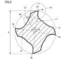
- each of peripheral cutting edge portion 3 and flute portion 4 is determined as follows.
- a circle S is a hypothetical circle that includes a cross section of blade head 1 inside and that is drawn by connecting cutting edge tips 3a.
- Circle S has a diameter D. It should be noted that each of cutting edge tips 3a is a portion serving as a starting point via which the workpiece is cut.
- Peripheral cutting edge portion 3 A circle S1 is a hypothetical circle that has a central point corresponding to a contact point between cutting edge tip 3a and circle S and that has a radius D1 of 2/10D. In the outer circumference of base member 11, peripheral cutting edge portion 3 represents a region located within (and on) hypothetical circle S1.
- Lines L1 and L2 are hypothetical lines that connect facing cutting edge tips 3a to central point P of circle S.
- a line L3 is a hypothetical line that equally divides an angle 2 ⁇ formed by line L1 and line L2.
- a circle S2 is a hypothetical circle that has a central point corresponding to a contact point between line L3 and the outer circumference of base member 11 and that has a radius D2 of 1/10D.
- flute portion 4 represents a region located within (and on) hypothetical circle S2.
- base member 11 As the material of base member 11, a material conventionally known for a base member 11 of a rotating tool can be used without a particular limitation. Examples thereof include tungsten carbide (WC) based cemented carbide, cermet, a high-speed steel, ceramics, a cubic boron nitride sintered material, a diamond sintered material, and the like. It should be noted that base member 11 may be formed in one piece or may be formed in a combination of a plurality of components.
- WC tungsten carbide
- Coating film 12 is configured to coat the entire surface of base member 11 or a portion of the surface. Moreover, coating film 12 may have a single layer structure constituted of one layer, or may have a multi-layer structure constituted of two or more layers. In a reference example, a ratio B/A of a film thickness B of coating film 12 coating a surface of flute portion 4 to a film thickness A of coating film 12 coating a surface of cutting edge portion is not less than 0.8 (in the present invention it is 1.01 to 3.90). Accordingly, rotating tool 10 can be excellent in wear resistance.
- rotating tool 10 of the present embodiment is excellent in wear resistance in comparison with a conventional rotating tool.
- An expected wear resistance of a rotating tool from a design of the rotating tool is found from not only a physical property of the base member but also a physical property of the coating film provided on the surface of the base member.
- the conventional rotating tool tends to be unable to exhibit a wear resistance comparable to the wear resistance expected from the design.
- ratio B/A of film thickness B of the coating film formed on the surface of the flute portion to film thickness A of the coating film formed on the surface of the cutting edge portion is too small, i.e., about not more than 0.5, with the result that the wear resistance of the flute portion is lower than the wear resistance expected from the design and accordingly the wear resistance of the rotating tool is insufficient.
- Such a too small ratio is related with a fact that the coating film of the conventional rotating tool is produced by the MS method or the AIP method.
- the MS method since an ionization ratio of atoms serving as a target in plasma is too low, the ions cannot be sufficiently drawn to the flute portion by a substrate bias.
- the ionization ratio is sufficient; however, pressure in the chamber needs to be high in order to reduce the number of metal droplets generated from the target. Accordingly, the pressure in the chamber becomes too high, with the result that a mean free path of the ions tends to be too short. When the mean free path of the ions is short, the ions are likely to be dispersed, thus making it difficult to draw the ions to the flute portion.
- a coating film having a uniform film thickness cannot be formed on a surface of a base member for a rotating tool having a shape more complicated than those of other tools, thus resulting in a small film thickness B of the coating film on the flute portion located in the complicated portion of the base member.
- film thickness B When film thickness B is small, wear of the flute portion is promoted faster than expected. This leads to a decreased smoothness of the flute portion to result in a decreased dischargeability for swarf. Accordingly, a cutting resistance is increased. When the cutting resistance is increased, wear at the cutting edge portion is also promoted faster than expected, with the result that the wear resistance of the rotating tool becomes insufficient. Moreover, if the coating film is formed to have a sufficiently large film thickness B at the flute portion, film thickness A thereof at the cutting edge portion becomes too large. Accordingly, adhesion between the coating film and the base member is decreased, thereby causing a decreased wear resistance.
- rotating tool 10 of the present embodiment includes coating film 12 formed using the HiPIMS method instead of the MS method and the AIP method.
- HiPIMS method large electric power is applied to the target at a short pulse, thereby achieving a high ionization ratio.
- the HiPIMS method is one type of sputtering, pressure in the chamber can be low.
- coating film 12 having the uniform film thickness is formed on the surface of base member 11, whereby the above-described ratio B/A can indicate a high value to be not less than 0.8 (not less than 0.8 in a reference example, 1.01 to 3.90 in the present invention). Therefore, the above-described problem in the conventional rotating tool can be solved by rotating tool 10 of the present embodiment.
- rotating tool 10 of the present embodiment can have a higher wear resistance than that of the conventional rotating tool. Further, the high wear resistance leads to not only a long life but also an improved cutting precision, thereby obtaining a good surface condition such as surface roughness in a workpiece.
- rotating tool 10 of the present embodiment is suitable as a high precision machining rotating tool.
- Film thickness A and film thickness B of coating film 12 can be measured by cutting rotating tool 10 in a longitudinal direction (lateral direction in Fig. 1 ) and observing the cross section using a scanning electron microscope (SEM).
- ratio B/A is determined in the following manner: film thicknesses A of arbitrary points (four points in total in the present embodiment) of the respective cutting edges are measured, film thicknesses B of arbitrary points (four points in total in the present embodiment) of the respective flute portions are measured, and the total value of all the values of measured film thicknesses B are divided by the total value of all the values of measured film thicknesses A.
- deviation of the arbitrary point of each of the cutting edges from the center (cutting edge tip 3a) of circle S1 is not more than 100 ⁇ m; and deviation of the arbitrary point of each of the flute portions from the center of circle S2 is not more than 100 ⁇ m.
- ratio B/A is preferably not less than 1 (reference example).
- rotating tool 10 can be more excellent in wear resistance.
- ratio B/A is preferably not more than 4.15.
- the wear resistance is excellent particularly when ratio B/A is 1.05 to 3.90; and the wear resistance is excellent more remarkably when ratio B/A is 1.22 to 3.90.
- film thickness A is not less than 0.1 ⁇ m and not more than 10 ⁇ m (hereinafter, such a notation will be also simply expressed as "0.1 to 10 ⁇ m").
- film thickness A is less than 0.1 ⁇ m, the functional characteristics (inclusive of the improved wear resistance) resulting from the inclusion of coating film 12 may be unlikely to be exhibited sufficiently.
- film thickness A is more than 10 ⁇ m, the adhesion between base member 11 and coating film 12 tends to be decreased.
- Film thickness A is more preferably 2.0 to 6.0 ⁇ m.
- coating film 12 of the present invention is composed of not less than one compound including: at least one element selected from a group consisting of a group 4 element (Ti, Zr, Hf, or the like), a group 5 element (V, Nb, Ta, or the like), a group 6 element (Cr, Mo, W, or the like) in the periodic table, aluminum (Al), and silicon (Si); and at least one element selected from a group consisting of boron (B), carbon (C), nitrogen (N), and oxygen (O).
- TiAlN, TiN, CrN, AlCrN, AlCrSiN, TiAlSiN, TiSiN, TiCN, TiAlON, and TiAlBNO are preferable.
- TiAlN, TiN, CrN, AlCrN, AlCrSiN, TiAlSiN, and TiCN are more preferable.
- a coating film 12 having a high hardness and more suitable for rotating tool 10 can be provided.
- Rotating tool 10 of the present embodiment can be produced by using the HiPIMS method to form coating film 12 on the surface of base member 11.
- the following describes a case where a coating film composed of TiAlN is formed as an exemplary coating film 12.
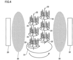
- Fig. 4 shows a state of arrangement of the base member within a chamber during formation of the coating film.
- targets 20 each serving as a source material of coating film 12 are disposed at the side walls of the chamber (not shown). It should be noted that Fig. 4 shows two targets 20 but the number of targets 20 is not particularly limited. For example, when coating film 12 composed of TiAlN is to be formed, a plurality of Ti targets and a plurality of Al targets can be disposed in the chamber.
- a turntable 21 is disposed.
- a plurality of placement tables (substrates) 23 are disposed at/along two rotation shafts 22.
- a plurality of base members 11 are placed.
- the number of rotation shafts 22 is not limited to that shown in Fig. 4 and may be two or more. In this case, the number of turntables 21 and placement tables 23 can also be increased in response to an increase in the number of the rotation shafts.
- Placement table 23 is electrically connected to a negative electrode of a bias power supply.
- the bias supply has a positive electrode that is connected to a ground and that is electrically connected to the chamber (not shown).
- a negative electrode of a short pulse power supply is connected to the target.
- the short pulse power supply has a positive electrode connected to a ground (not shown).
- coating film 12 inert gas and nitrogen gas are introduced into the chamber in vacuum and large electric power is applied to target 20 at a short pulse. Accordingly, plasma 30 is generated in the chamber. Then, ions are collided with target 20, whereby metal atoms and metal ions are brought out from target 20 to adhere to the surface of base member 11 together with the nitrogen atoms. It should be noted that turntable 21 and rotation shafts 22 are rotated in the respective directions of arrows shown in the figure. On this occasion, coating film 12 in which ratio B/A is not less than 0.8 can be formed by setting film formation conditions as follows.
- the pulse width is more preferably 100 ⁇ s to 1 ms, and the bias is preferably not more than 60 V.
- a film formation condition mode is more preferably set at a transition mode, and a partial pressure of the reactive gas (nitrogen gas in the present embodiment) is preferably in consideration of hysteresis loss.
- the base member was prepared.
- the base member of each of samples No. 1 to No. 8, No. 10 to No. 13 and A to F was composed of cemented carbide provided by Sumitomo Electric Industries, and had a shape "SSEHVL4160-R10" (with a diameter of 16 mm and four cutting edges).
- the base member of sample No. 9 was composed of cemented carbide provided by Sumitomo Electric Industries, and had a shape "SSEHVL4100-R10" (with a diameter of 10 mm and four cutting edges).
- the prepared base member was placed on a placement table (substrate) (see Fig. 4 ) in a chamber of an HiPIMS apparatus.
- a placement table substrate
- an alloy target of titanium (50 atom %) and aluminum (50 atom %) was placed as a target.
- the film formation process was performed under the following film formation conditions while introducing argon (Ar) gas and nitrogen (N 2 ) gas.
- film formation conditions other than the pulse width were the same.
- the pulse width of each sample is shown in Table 1. It should be noted that the film formation time was set at a time appropriate to attain a coating film having an intended film thickness.
- Pulse width Pulse time: 25 ⁇ s to 50 ms (changed for each sample; see Table 1)
- the "pulse power density” is a value obtained by dividing an "average power within a pulse” by an "area of a racetrack in a target surface".
- Test 3 Pulse Width (ms) Bias Voltage (-V) Film Thickness A ( ⁇ m) Film Thickness B ( ⁇ m) Ratio (B/A) Cutting Distance (m) Ra ( ⁇ m) Feed Force (N) Ra ( ⁇ m) Feed Force (N) 1* HiPIMS Ti 50 Al 50 N End Mill 0.025 60 2.67 1.71 0.64 5.0 - - - - 2* HiPIMS Ti 50 Al 50 N End Mill 0.05 60 2.78 1.97 0.71 5.5 - - - - 3* HiPIMS Ti 50 Al 50 N End Mill 0.1 60 2.91 2.68 0.92 7.5 - - - - 4 HiPIMS Ti 50 Al 50 N End Mill 0.
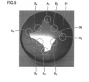
- a cutting machine including a diamond rotating blade was used to partially cut the cutting edge portion of the rotating tool, thereby obtaining a cut piece 50.
- obtained cut piece 50 was embedded in a resin 51 and a cross section of cut piece 50 (surface of cut piece 50 observed in Fig. 5 ) was observed by an SEM.
- Film thicknesses A of the coating film coating the surfaces of cutting edge portions A 1 to A 4 were measured, and film thicknesses B of the coating film coating the surfaces of flute portions B 1 to B 4 were measured. From the respective average values of the film thicknesses A, B, the ratio therebetween was determined.
- the film thickness of the coating film coating each of the surfaces of cutting edge portions A 1 to A 4 was measured at one arbitrary point in the outer circumference of the blade head with a deviation of not more than 100 ⁇ m from the cutting edge tip.
- the film thickness of the coating film coating each of the surfaces of flute portions B 1 to B 4 was measured at one arbitrary point with a deviation of not more than 100 ⁇ m (see Fig. 3 ) from a position at which line L4 is in contact with the outer circumference of blade head 1.
- the value of the total of the four film thicknesses measured at the flute portions was divided by the value of the total of the four film thicknesses measured at the cutting edge portions, thereby obtaining ratio B/A. Results thereof are shown in Table 1.
- the "amount of cut ap" represents an amount of cut in the axial direction of the rotating tool.
- Produced sample No. 8 was subjected to a cutting test (processed side surface quality test) 2 to evaluate tool performance. Cutting conditions were set as described below. A surface roughness (Ra) of a workpiece after the cutting test and feed force (N) during cutting were measured. Results thereof are shown in Table 1. In Table 1, a smaller Ra indicates a more smooth surface of the workpiece, and a smaller feed force (N) indicates a smaller resistance between the workpiece and the rotating tool.
- the “amount of cut ap” represents an amount of cut in the axial direction of the rotating tool
- the “amount of cut ae” represents an amount of cut in the radial direction of the rotating tool
- Produced sample No. 9 was subjected to a cutting test (processed side surface quality test) 3 to evaluate tool performance. Cutting conditions were set as described below. A surface roughness (Ra) of the workpiece after the cutting test and feed force (N) during cutting were measured. Results thereof are shown in Table 1. In Table 1, a smaller Ra indicates a more smooth surface of the workpiece, and a smaller feed force (N) indicates a smaller resistance between the workpiece and the rotating tool.
- the “amount of cut ap” represents an amount of cut in the axial direction of the rotating tool
- the “amount of cut ae” represents an amount of cut in the radial direction of the rotating tool
- Rotating tools (end mills) of samples No. 14 to No. 16 were obtained in the same manner as that for sample No. 7 except that the pulse power density was changed as shown in Table 2.
- Rotating tools (end mills) of samples No. 17 to No. 20 were obtained in the same manner as that for sample No. 7 except that the pulse average power was changed as shown in Table 2.
- Rotating tools (end mills) of samples No. 21 to No. 24 were obtained in the same manner as that for sample No. 7 except that the bias voltage was changed as shown in Table 2.
- the film thickness of the coating film of each of the obtained rotating tools of samples No. 14 to No. 24 was measured by the same method as that described above, and ratio B/A was determined. Results thereof are shown in Table 2. [Table 2] Sample No.
- ratio B/A of the coating film in order to obtain ratio B/A of the coating film to be not less than 0.8, it was found preferable to set the pulse power density to be not less than 1.5 kW/cm 2 , set the pulse average power to be not less than 4 kW, and set the bias voltage to be not more than 80 V.
- Rotating tools (end mills) of samples No. 25 to No. 31 were obtained in the same manner as that for sample No. 7 except that the film formation time was changed as shown in Table 3.
- the film thickness of the coating film of each of the obtained rotating tools of samples No. 25 to No. 31 was measured by the same method as that described above, and ratio B/A was determined.
- cutting test 1 was performed using each of the rotating tools of samples No. 25 to No. 31 to measure a cutting distance until the tool life was reached. Results thereof are shown in Table 3. [Table 3] Sample No.
- ratio B/A became not less than 0.8 when film thickness A of the coating film was not less than 0.07 ⁇ m.
- ratio B/A can be readily controlled to be not less than 0.8 when film thickness A of the coating film is not less than 0.07 ⁇ m.
- the cutting distance of each of samples No. 7, No. 28, and No. 29 was particularly long. Based on this fact, it was found that the wear resistance is particularly excellent when film thickness A of the coating film is 2.08 to 5.71 ⁇ m.
- Rotating tools (end mills) of samples No. 32 to No. 41 and G were obtained in the same manner as that for sample No. 7 except that the composition of the coating film was changed as shown in Table 4. It should be noted that in order to change the composition of the coating film as shown in Table 4, a type of target in the chamber and a type of gas to be introduced were changed appropriately. The film thickness of the coating film of each of the obtained rotating tools of samples No. 32 to No. 41 and G was measured by the same method as that described above, and ratio B/A was determined. Results thereof are shown in Table 4. [Table 4] Sample No.
- ratio B/A became not less than 0.8 also in each of samples No. 32 to No. 41 and G.
- the film thickness of the coating film of each of the obtained rotating tools of samples No. 42 to No. 44 was measured by the same method as that described above, and ratio B/A was determined. Results thereof are shown in Table 5.
- Each of produced samples No. 42 to No. 44 was subjected to a cutting test (drilling test) 4 to evaluate a tool life. Cutting conditions were set as described below. Thrust (N) and torque (N) during the cutting were measured. Results thereof are shown in Table 5. In Table 5, larger thrust (N) and torque (N) indicate a larger cutting resistance.
- the base member of each of samples No. 45 to No. 49, No. 51 to No. 53 and No. 55 to No. 61 was composed of cemented carbide provided by Sumitomo Electric Industries, and had a shape "SSEHVL4160-R10" (with a diameter of 16 mm and four cutting edges).
- the base member of sample No. 50 was composed of cemented carbide provided by Sumitomo Electric Industries, and had a shape "SSEHVL4100-R10" (with a diameter of 10 mm and four cutting edges).
- the prepared base member of sample No. 45 was placed on a placement table (substrate) in a chamber of an AIP apparatus. In the chamber, an alloy target of titanium (50 atom %) and aluminum (50 atom %) was placed as a target. Then, the film formation process was performed under the following film formation conditions while introducing argon (Ar) gas and nitrogen (N 2 ) gas. It should be noted that the film formation time was set at a time appropriate to attain a coating film having an intended film thickness.
- Arc current 150 A Bias voltage: 40 V Pressure in chamber: 4.5 Pa.
- rotating tools end mills or drill
- the arc current and/or the bias voltage were changed as shown in Table 6.
- Rotating tools (end mills) of samples No. 55 to No. 61 were obtained in the same manner as that for sample No. 45 except that the composition of the coating film and the bias voltage were changed as shown in Table 6.
- the film thickness of the coating film of each of the obtained rotating tools of samples No. 46 to No. 61 was measured by the same method as that described above, and ratio B/A was determined. Results thereof are shown in Table 6.
- ratio B/A was less than 0.8, i.e., was not more than 0.7.
- samples No. 47 to No. 51 and No. 54 were subjected to one of cutting tests 1 to 4, but had a wear resistance inferior to those of the rotating tools in each of which ratio B/A was not less than 0.8.
Landscapes
- Chemical & Material Sciences (AREA)
- Engineering & Computer Science (AREA)
- Mechanical Engineering (AREA)
- Chemical Kinetics & Catalysis (AREA)
- Materials Engineering (AREA)
- Metallurgy (AREA)
- Organic Chemistry (AREA)
- Physical Vapour Deposition (AREA)
- Drilling Tools (AREA)
- Cutting Tools, Boring Holders, And Turrets (AREA)
Description
- The present invention relates to a rotating tool including a base member and a coating film formed on the base member.
- As a tool, there has been known a tool in which a hard coating film such as TiAlN is provided on a surface of a hard base member such as WC based cemented carbide. By providing such a coating film on the surface of the base member, the wear resistance of the base member can be improved, thereby achieving an extended life of the tool.
- For example, each of Japanese Patent Laying-Open No.
2012-36506 -
JP2005022071A JPS61288914A - PTD 1: Japanese Patent Laying-Open No.
2012-36506 -
- NPD 1: Machining of Difficult-To-Machine Materials by PVD Coated Tool, Shimamura et al., Journal of the Japan Society for Abrasive Technology Vol.57, No.8 (2013), 536-541
- NPD 2: An introduction to thin film processing using high-power impulse magnetron sputtering, J. Mater. Res., vol.27, No.5 (2012), 780-792
- However, in the rotating tool including the coating film formed by each of the above-described conventional techniques, a degree of improvement in wear resistance by the inclusion of the coating film may be insufficient.
- In view of the above problem, the present disclosure has an object to provide a rotating tool having an excellent wear resistance.
- A rotating tool according to one embodiment of the present invention is according to
claim 1. - According to the description above, a rotating tool having an excellent wear resistance can be provided.
-
-
Fig. 1 is a schematic plan view showing an exemplary rotating tool according to one embodiment of the present embodiment. -
Fig. 2 is a cross sectional view taken along an X-X line shown inFig. 1 . -
Fig. 3 is a schematic view for illustrating each region of a peripheral cutting edge portion and a flute portion. -
Fig. 4 is a schematic view showing a state of arrangement of a base member in a chamber during formation of a coating film. -
Fig. 5 illustrates a method of measuring a film thickness. - First, embodiments of the present invention are listed and described.
- As a result of study to solve the above-described problem, the present inventors found that: in the conventional rotating tool, the film thickness of the coating film formed on the surface of the flute portion is remarkably smaller than the film thickness of the coating film formed on the surface of the cutting edge portion, thus resulting in a decreased wear resistance of the rotating tool. Based on this knowledge, the present inventors considered that there is a problem in a conventional method of forming a coating film such as the AIP method or the MS method, and conducted diligent study by paying attention to a High Power Impulse Magnetron Sputtering (HiPIMS) method described in J. Mater. Res., vol.27, No.5 (2012), 780-792 (Non-Patent Document 2) as an alternative to the foregoing formation method. As a result, a rotating tool having an excellent wear resistance has been completed.
- [1] A rotating tool according to one embodiment of the present invention is according to
claim 1.
According to the rotating tool, wear of the coating film coating the surface of the flute portion can be suppressed, thereby attaining an excellent wear resistance. - [2] The rotating tool is an end mill. Conventionally, in an end mill, the above-described ratio tends to be particularly small. However, according to the above-described rotating tool, the ratio is larger than that of the conventional one, thereby attaining an excellent wear resistance.
- [3] The rotating tool is a drill. Conventionally, in a drill, the above-described ratio tends to be particularly small. However, according to the above-described rotating tool, the ratio is larger than that of the conventional one, thereby attaining an excellent wear resistance.
- [4] In the rotating tool, the ratio B/A is not less than 1.01. Accordingly, the wear resistance can be more excellent.
- [5] In the rotating tool, the film thickness A is not less than 0.1 µm and not more than 10 µm. Accordingly, the wear resistance can be more excellent.
- [6] In the rotating tool, the film thickness A is not less than 2.0 µm and not more than 6.0 µm. Accordingly, the wear resistance can be more excellent.
- [7] In the rotating tool, a material of the coating film is not less than one compound composed of: at least one element selected from a group consisting of a
group 4 element, agroup 5 element, a group 6 element in a periodic table, aluminum, and silicon; and at least one element selected from a group consisting of boron, carbon, nitrogen, and oxygen. Accordingly, the rotating tool can include a coating film having a high hardness. - Although the following describes one embodiment (hereinafter, referred to as "the present embodiment") of the present invention in detail, the present embodiment is not limited thereto.
-
Fig. 1 is a schematic plan view showing an exemplary rotating tool according to the present embodiment.Fig. 2 is a cross sectional view taken along an X-X line shown inFig. 1 . In the present embodiment, an end mill with four cutting edges will be illustrated. - With reference to
Fig. 1 and Fig. 2 , a rotatingtool 10 includes: abase member 11 serving as a main body of rotatingtool 10; and acoating film 12 that coats a surface ofbase member 11. The whole surface ofbase member 11 included in rotatingtool 10 may be coated withcoating film 12, or a part ofbase member 11 may be coated therewith. For example, a surface ofbase member 11 constituting ashank 2 may not be coated and only a surface of the base member constituting ablade head 1 may be coated withcoating film 12. - In the present embodiment, an end mill will be illustrated as rotating
tool 10; however, examples of rotatingtool 10 include a drill in addition to the end mill. Moreover, in addition to those above, examples of rotatingtool 10 include a rooter, a reamer, and the like as long as rotatingtool 10 includes:base member 11 having a cutting edge portion for cutting a workpiece at least in contact with the workpiece, and a flute portion for bringing swarf to outside; andcoating film 12. Particularly, rotatingtool 10 of the present embodiment can be suitably used as a rotating tool for high precision machining. -
Base member 11 serves as the main body of rotatingtool 10 and has a shape corresponding to that of rotatingtool 10.Base member 11 includesblade head 1 andshank 2.Blade head 1 includes peripheralcutting edge portions 3,flute portions 4, and an endcutting edge portion 5. Each peripheralcutting edge portion 3 and end cuttingedge portion 5 are regions for cutting the workpiece, and eachflute portion 4 is a region for bringing swarf produced by the cutting to outside. Particularly, peripheralcutting edge portion 3 includes a cutting edge portion (not shown), which is a portion having no relief angle relative to the workpiece. The cutting edge portion is a portion to be in contact with the workpiece during cutting. - Here, in the present specification, each of peripheral
cutting edge portion 3 andflute portion 4 is determined as follows. With reference toFig. 3 , a circle S is a hypothetical circle that includes a cross section ofblade head 1 inside and that is drawn by connectingcutting edge tips 3a. Circle S has a diameter D. It should be noted that each of cuttingedge tips 3a is a portion serving as a starting point via which the workpiece is cut. - Peripheral cutting edge portion 3: A circle S1 is a hypothetical circle that has a central point corresponding to a contact point between cutting
edge tip 3a and circle S and that has a radius D1 of 2/10D. In the outer circumference ofbase member 11, peripheralcutting edge portion 3 represents a region located within (and on) hypothetical circle S1. - Flute portion 4: Lines L1 and L2 are hypothetical lines that connect facing cutting
edge tips 3a to central point P of circle S. A line L3 is a hypothetical line that equally divides an angle 2α formed by line L1 and line L2. A circle S2 is a hypothetical circle that has a central point corresponding to a contact point between line L3 and the outer circumference ofbase member 11 and that has a radius D2 of 1/10D. In the outer circumference ofbase member 11,flute portion 4 represents a region located within (and on) hypothetical circle S2. - As the material of
base member 11, a material conventionally known for abase member 11 of a rotating tool can be used without a particular limitation. Examples thereof include tungsten carbide (WC) based cemented carbide, cermet, a high-speed steel, ceramics, a cubic boron nitride sintered material, a diamond sintered material, and the like. It should be noted thatbase member 11 may be formed in one piece or may be formed in a combination of a plurality of components. -
Coating film 12 is configured to coat the entire surface ofbase member 11 or a portion of the surface. Moreover,coating film 12 may have a single layer structure constituted of one layer, or may have a multi-layer structure constituted of two or more layers. In a reference example, a ratio B/A of a film thickness B ofcoating film 12 coating a surface offlute portion 4 to a film thickness A ofcoating film 12 coating a surface of cutting edge portion is not less than 0.8 (in the present invention it is 1.01 to 3.90). Accordingly, rotatingtool 10 can be excellent in wear resistance. - The following describes a reason why rotating
tool 10 of the present embodiment is excellent in wear resistance in comparison with a conventional rotating tool. An expected wear resistance of a rotating tool from a design of the rotating tool is found from not only a physical property of the base member but also a physical property of the coating film provided on the surface of the base member. However, the conventional rotating tool tends to be unable to exhibit a wear resistance comparable to the wear resistance expected from the design. Regarding this, the present inventors have found the following knowledge: in the conventional rotating tool, ratio B/A of film thickness B of the coating film formed on the surface of the flute portion to film thickness A of the coating film formed on the surface of the cutting edge portion is too small, i.e., about not more than 0.5, with the result that the wear resistance of the flute portion is lower than the wear resistance expected from the design and accordingly the wear resistance of the rotating tool is insufficient. - Such a too small ratio is related with a fact that the coating film of the conventional rotating tool is produced by the MS method or the AIP method. Specifically, in the MS method, since an ionization ratio of atoms serving as a target in plasma is too low, the ions cannot be sufficiently drawn to the flute portion by a substrate bias. In the AIP method, the ionization ratio is sufficient; however, pressure in the chamber needs to be high in order to reduce the number of metal droplets generated from the target. Accordingly, the pressure in the chamber becomes too high, with the result that a mean free path of the ions tends to be too short. When the mean free path of the ions is short, the ions are likely to be dispersed, thus making it difficult to draw the ions to the flute portion. Accordingly, in each of these methods, a coating film having a uniform film thickness cannot be formed on a surface of a base member for a rotating tool having a shape more complicated than those of other tools, thus resulting in a small film thickness B of the coating film on the flute portion located in the complicated portion of the base member.
- When film thickness B is small, wear of the flute portion is promoted faster than expected. This leads to a decreased smoothness of the flute portion to result in a decreased dischargeability for swarf. Accordingly, a cutting resistance is increased. When the cutting resistance is increased, wear at the cutting edge portion is also promoted faster than expected, with the result that the wear resistance of the rotating tool becomes insufficient. Moreover, if the coating film is formed to have a sufficiently large film thickness B at the flute portion, film thickness A thereof at the cutting edge portion becomes too large. Accordingly, adhesion between the coating film and the base member is decreased, thereby causing a decreased wear resistance.
- On the other hand, rotating
tool 10 of the present embodiment includescoating film 12 formed using the HiPIMS method instead of the MS method and the AIP method. In the HiPIMS method, large electric power is applied to the target at a short pulse, thereby achieving a high ionization ratio. Moreover, since the HiPIMS method is one type of sputtering, pressure in the chamber can be low. - By using the HiPIMS method, coating
film 12 having the uniform film thickness is formed on the surface ofbase member 11, whereby the above-described ratio B/A can indicate a high value to be not less than 0.8 (not less than 0.8 in a reference example, 1.01 to 3.90 in the present invention). Therefore, the above-described problem in the conventional rotating tool can be solved by rotatingtool 10 of the present embodiment. Hence, rotatingtool 10 of the present embodiment can have a higher wear resistance than that of the conventional rotating tool. Further, the high wear resistance leads to not only a long life but also an improved cutting precision, thereby obtaining a good surface condition such as surface roughness in a workpiece. - Moreover, when the film thickness of the coating film needs to be small as in a high precision machining rotating tool, film thickness B in the flute portion becomes too small in the conventional rotating tool, with the result that the tool life tends to be very short. According to rotating
tool 10 of the present embodiment, however, this can be overcome. Therefore, rotatingtool 10 of the present embodiment is suitable as a high precision machining rotating tool. - Film thickness A and film thickness B of
coating film 12 can be measured by cutting rotatingtool 10 in a longitudinal direction (lateral direction inFig. 1 ) and observing the cross section using a scanning electron microscope (SEM). In the present specification, ratio B/A is determined in the following manner: film thicknesses A of arbitrary points (four points in total in the present embodiment) of the respective cutting edges are measured, film thicknesses B of arbitrary points (four points in total in the present embodiment) of the respective flute portions are measured, and the total value of all the values of measured film thicknesses B are divided by the total value of all the values of measured film thicknesses A. It should be noted that with reference toFig. 3 , for example, when rotatingtool 10 has four cutting edges and has a blade head with a diameter (diameter of circle S inFig. 3 ) of about 10 mm, it is preferable that: deviation of the arbitrary point of each of the cutting edges from the center (cuttingedge tip 3a) of circle S1 is not more than 100 µm; and deviation of the arbitrary point of each of the flute portions from the center of circle S2 is not more than 100 µm. - In
coating film 12, ratio B/A is preferably not less than 1 (reference example). In this case, rotatingtool 10 can be more excellent in wear resistance. Moreover, from results of Examples described later (see Table 1), it is confirmed thatrotating tool 10 is more excellent in wear resistance when ratio B/A is 1.01 to 3.90 (present invention), specifically, is not less than 1.01. Moreover, it is also confirmed that ratio B/A is preferably not more than 4.15. Further, it is also confirmed that: the wear resistance is excellent particularly when ratio B/A is 1.05 to 3.90; and the wear resistance is excellent more remarkably when ratio B/A is 1.22 to 3.90. - Moreover, in the present invention, in coating
film 12, film thickness A is not less than 0.1 µm and not more than 10 µm (hereinafter, such a notation will be also simply expressed as "0.1 to 10 µm"). When film thickness A is less than 0.1 µm, the functional characteristics (inclusive of the improved wear resistance) resulting from the inclusion ofcoating film 12 may be unlikely to be exhibited sufficiently. When film thickness A is more than 10 µm, the adhesion betweenbase member 11 andcoating film 12 tends to be decreased. Film thickness A is more preferably 2.0 to 6.0 µm. - As the material of
coating film 12, a material conventionally known for acoating film 12 of a rotating tool can be used without a particular limitation (reference example). Particularly,coating film 12 of the present invention is composed of not less than one compound including: at least one element selected from a group consisting of agroup 4 element (Ti, Zr, Hf, or the like), agroup 5 element (V, Nb, Ta, or the like), a group 6 element (Cr, Mo, W, or the like) in the periodic table, aluminum (Al), and silicon (Si); and at least one element selected from a group consisting of boron (B), carbon (C), nitrogen (N), and oxygen (O). - Among these, TiAlN, TiN, CrN, AlCrN, AlCrSiN, TiAlSiN, TiSiN, TiCN, TiAlON, and TiAlBNO are preferable. TiAlN, TiN, CrN, AlCrN, AlCrSiN, TiAlSiN, and TiCN are more preferable. In this case, a
coating film 12 having a high hardness and more suitable for rotatingtool 10 can be provided. - It should be noted that when a compound is indicated by a chemical formula such as TiAlN in the present specification, it is assumed that the compound includes ones with all the conventionally known atomic ratios when the atomic ratio of the compound is not particularly limited, and is not necessarily limited to ones with atomic ratios falling within the stoichiometric range.
- Rotating
tool 10 of the present embodiment can be produced by using the HiPIMS method to formcoating film 12 on the surface ofbase member 11. With reference toFig. 4 , the following describes a case where a coating film composed of TiAlN is formed as anexemplary coating film 12. -
Fig. 4 shows a state of arrangement of the base member within a chamber during formation of the coating film. With reference toFig. 4 , targets 20 each serving as a source material ofcoating film 12 are disposed at the side walls of the chamber (not shown). It should be noted thatFig. 4 shows twotargets 20 but the number oftargets 20 is not particularly limited. For example, when coatingfilm 12 composed of TiAlN is to be formed, a plurality of Ti targets and a plurality of Al targets can be disposed in the chamber. - At the center between the plurality of targets disposed in the chamber, a
turntable 21 is disposed. Onturntable 21, a plurality of placement tables (substrates) 23 are disposed at/along tworotation shafts 22. On each placement table 23, a plurality ofbase members 11 are placed. It should be noted that the number ofrotation shafts 22 is not limited to that shown inFig. 4 and may be two or more. In this case, the number ofturntables 21 and placement tables 23 can also be increased in response to an increase in the number of the rotation shafts. - Placement table 23 is electrically connected to a negative electrode of a bias power supply. The bias supply has a positive electrode that is connected to a ground and that is electrically connected to the chamber (not shown). Moreover, a negative electrode of a short pulse power supply is connected to the target. The short pulse power supply has a positive electrode connected to a ground (not shown).
- During the formation of coating
film 12, inert gas and nitrogen gas are introduced into the chamber in vacuum and large electric power is applied to target 20 at a short pulse. Accordingly,plasma 30 is generated in the chamber. Then, ions are collided withtarget 20, whereby metal atoms and metal ions are brought out fromtarget 20 to adhere to the surface ofbase member 11 together with the nitrogen atoms. It should be noted thatturntable 21 androtation shafts 22 are rotated in the respective directions of arrows shown in the figure. On this occasion,coating film 12 in which ratio B/A is not less than 0.8 can be formed by setting film formation conditions as follows. -
- Pulse width (pulse time): 100 µs to 10 ms
- Pulse power density: not less than 1.5 kW/cm2
- Pulse average power: not less than 4 kW
- Bias voltage: not more than 80 V
- Pressure in chamber: not more than 1 Pa
- Film formation time: 4 to 650 minutes.
- Regarding the film formation conditions above, the pulse width is more preferably 100 µs to 1 ms, and the bias is preferably not more than 60 V. Moreover, a film formation condition mode is more preferably set at a transition mode, and a partial pressure of the reactive gas (nitrogen gas in the present embodiment) is preferably in consideration of hysteresis loss.
- While the present invention will be described in more detail with reference to Examples, the present invention is not limited thereto. In each of samples No. 1 to No. 44 and A to G, a coating film was formed on a base member by the HiPIMS method. In each of samples No. 45 to No. 61, a coating film was formed on a base member by the AlP method.
- First, the base member was prepared. The base member of each of samples No. 1 to No. 8, No. 10 to No. 13 and A to F was composed of cemented carbide provided by Sumitomo Electric Industries, and had a shape "SSEHVL4160-R10" (with a diameter of 16 mm and four cutting edges). The base member of sample No. 9 was composed of cemented carbide provided by Sumitomo Electric Industries, and had a shape "SSEHVL4100-R10" (with a diameter of 10 mm and four cutting edges).
- The prepared base member was placed on a placement table (substrate) (see
Fig. 4 ) in a chamber of an HiPIMS apparatus. In the chamber, an alloy target of titanium (50 atom %) and aluminum (50 atom %) was placed as a target. Then, the film formation process was performed under the following film formation conditions while introducing argon (Ar) gas and nitrogen (N2) gas. Regarding the respective samples, film formation conditions other than the pulse width were the same. The pulse width of each sample is shown in Table 1. It should be noted that the film formation time was set at a time appropriate to attain a coating film having an intended film thickness. - Pulse width (pulse time): 25 µs to 50 ms (changed for each sample; see Table 1)
- Pulse power density: 1.5 kW/cm2
- Pulse average power: 6 kW
- Bias voltage: 30 to 60 V (changed for each sample; see Table 1)
- Pressure in chamber: 0.60 to 0.70 Pa
- Partial pressure of argon gas: 0.4 Pa
- Mode: transition mode
- It should be noted that the "pulse power density" is a value obtained by dividing an "average power within a pulse" by an "area of a racetrack in a target surface".
[Table 1] Sample No. Production Method Type of Coating Film Tool Film Formation Conditions Film Thickness of Coating Film Test 1 Test 2 Test 3 Pulse Width (ms) Bias Voltage (-V) Film Thickness A (µm) Film Thickness B (µm) Ratio (B/A) Cutting Distance (m) Ra (µm) Feed Force (N) Ra (µm) Feed Force (N) 1* HiPIMS Ti50Al50N End Mill 0.025 60 2.67 1.71 0.64 5.0 - - - - 2* HiPIMS Ti50Al50N End Mill 0.05 60 2.78 1.97 0.71 5.5 - - - - 3* HiPIMS Ti50Al50N End Mill 0.1 60 2.91 2.68 0.92 7.5 - - - - 4 HiPIMS Ti50Al50N End Mill 0.25 60 2.99 3.02 1.01 9.0 - - - - 5* HiPIMS Ti50Al50N End Mill 0.5 60 3.11 3.02 0.97 8.5 - - - - 6 HiPIMS Ti50Al50N End Mill 0.75 60 3.20 3.36 1.05 10.0 - - - - 7* HiPIMS Ti50Al50N End Mill 1 60 3.02 2.69 0.89 8.0 - - - 8* HiPIMS Ti50Al50N End Mill 2.5 60 2.35 1.94 0.82 - 0.35 550 - - 9 HiPIMS Ti50Al50N End Mill 2.5 60 2.13 2.24 1.05 - - - 0.31 155 10* HiPIMS Ti50Al50N End Mill 5 60 3.24 2.72 0.84 7.0 - - - - 11* HiPIMS Ti50Al50N End Mill 10 60 3.12 2.53 0.81 8.0 - - - - 12* HiPIMS Ti50Al50N End Mill 20 60 3.38 2.60 0.77 - - - - - 13* HiPIMS Ti50Al50N End Mill 50 60 2.98 1.79 0.60 - - - - - A HiPIMS Ti50Al50N End Mill 0.6 60 3.02 3.68 1.22 11.5 - - - - B HiPIMS Ti50Al50N End Mill 0.625 50 3.28 4.92 1.50 12 - - - - C HiPIMS Ti50Al50N End Mill 0.65 40 2.95 6.11 2.07 12.5 - - - - D HiPIMS Ti50Al50N End Mill 0.675 30 2.89 7.46 2.58 13.5 - - - - E HiPIMS Ti50Al50N End Mill 0.7 30 2.81 10.96 3.90 11.0 - - - - F* HiPIMS Ti50Al50N End Mill 0.725 30 2.77 11.50 4.15 8.5 - - - - *Reference Examples - For each of the rotating tools (end mills) of samples No. 1 to No. 13 and A to F obtained by the above-described film formation process, film thickness A of the coating film coating the surface of the cutting edge portion and film thickness B of the coating film coating the surface of the flute portion were measured in the coating film thereof. Then, ratio B/A was determined.
- Specifically, first, a cutting machine including a diamond rotating blade was used to partially cut the cutting edge portion of the rotating tool, thereby obtaining a
cut piece 50. Next, as shown inFig. 5 , obtainedcut piece 50 was embedded in aresin 51 and a cross section of cut piece 50 (surface ofcut piece 50 observed inFig. 5 ) was observed by an SEM. Film thicknesses A of the coating film coating the surfaces of cutting edge portions A1 to A4 were measured, and film thicknesses B of the coating film coating the surfaces of flute portions B1 to B4 were measured. From the respective average values of the film thicknesses A, B, the ratio therebetween was determined. - Specifically, the film thickness of the coating film coating each of the surfaces of cutting edge portions A1 to A4 was measured at one arbitrary point in the outer circumference of the blade head with a deviation of not more than 100 µm from the cutting edge tip. The film thickness of the coating film coating each of the surfaces of flute portions B1 to B4 was measured at one arbitrary point with a deviation of not more than 100 µm (see
Fig. 3 ) from a position at which line L4 is in contact with the outer circumference ofblade head 1. Then, the value of the total of the four film thicknesses measured at the flute portions was divided by the value of the total of the four film thicknesses measured at the cutting edge portions, thereby obtaining ratio B/A. Results thereof are shown in Table 1. - Each of produced samples No. 1 to No. 7, No. 10, No. 11 and A to F was subjected to a cutting test (flute processing life test) 1 to evaluate a tool life. Cutting conditions were set as described below. A cutting distance was measured until the tool life was reached, specifically, until the maximum wear of the cutting edge portion became 0.1 mm. Results thereof are shown in Table 1. In Table 1, a longer cutting distance indicates a longer tool life.
- Workpiece: stainless steel (SUS304)
Amount of cut ap: 4.8 mm
Rotational speed: 1200 /min
Feed speed: 130 mm/min
Air blow: performed - Here, the "amount of cut ap" represents an amount of cut in the axial direction of the rotating tool.
- Produced sample No. 8 was subjected to a cutting test (processed side surface quality test) 2 to evaluate tool performance. Cutting conditions were set as described below. A surface roughness (Ra) of a workpiece after the cutting test and feed force (N) during cutting were measured. Results thereof are shown in Table 1. In Table 1, a smaller Ra indicates a more smooth surface of the workpiece, and a smaller feed force (N) indicates a smaller resistance between the workpiece and the rotating tool.
- Workpiece: stainless steel (SUS304)
Cutting speed: 30 m/min
Feed speed (fz): 0.083 mm/blade
Amount of cut ap: 16.0 mm
Amount of cut ae: 1.6 mm
Air blow: performed - Here, the "amount of cut ap" represents an amount of cut in the axial direction of the rotating tool, and the "amount of cut ae" represents an amount of cut in the radial direction of the rotating tool.
- Produced sample No. 9 was subjected to a cutting test (processed side surface quality test) 3 to evaluate tool performance. Cutting conditions were set as described below. A surface roughness (Ra) of the workpiece after the cutting test and feed force (N) during cutting were measured. Results thereof are shown in Table 1. In Table 1, a smaller Ra indicates a more smooth surface of the workpiece, and a smaller feed force (N) indicates a smaller resistance between the workpiece and the rotating tool.
- Workpiece: stainless steel (SUS304)
Cutting speed: 50 m/min
Feed speed (fz): 0.050 mm/blade
Amount of cut ap: 10.0 mm
Amount of cut ae: 1.0 mm
Air blow: performed - Here, the "amount of cut ap" represents an amount of cut in the axial direction of the rotating tool, and the "amount of cut ae" represents an amount of cut in the radial direction of the rotating tool.
- As shown in Table 1, regarding cutting
test 1, a high tool life was confirmed in each of samples No. 3 to No. 7, No. 10, No. 11 and A to F in each of which ratio B/A was not less than 0.8. Moreover, regarding cuttingtests - Rotating tools (end mills) of samples No. 14 to No. 16 were obtained in the same manner as that for sample No. 7 except that the pulse power density was changed as shown in Table 2. Rotating tools (end mills) of samples No. 17 to No. 20 were obtained in the same manner as that for sample No. 7 except that the pulse average power was changed as shown in Table 2. Rotating tools (end mills) of samples No. 21 to No. 24 were obtained in the same manner as that for sample No. 7 except that the bias voltage was changed as shown in Table 2. The film thickness of the coating film of each of the obtained rotating tools of samples No. 14 to No. 24 was measured by the same method as that described above, and ratio B/A was determined. Results thereof are shown in Table 2.
[Table 2] Sample No. Production Method Type of Coating Film Tool Film Formation Conditions Film Thickness of Coating Film Pulse Power Density (kW/cm2) Average Power (kW) Bias Voltage (-V) Film Thickness A (µm) Film Thickness B (µm) Ratio (B/A) 7* HiPIMS Ti50Al50N End mill 1.5 6 60 3.02 2.69 0.89 14* HiPIMS Ti50Al50N End Mill 0.5 6 60 3.14 2.07 0.66 15* HiPIMS Ti50Al50 N End Mill 1 6 60 3.00 2.16 0.72 16* HiPIMS Ti50Al50 N End Mill 2 6 60 2.78 2.42 0.87 17* HiPIMS Ti50Al50N End Mill 1.5 2 60 2.54 1.83 0.72 18* HiPIMS Ti50Al50N End Mill 1.5 4 60 2.79 2.34 0.84 19* HiPIMS Ti50Al50N End Mill 1.5 8 60 2.90 2.73 0.94 20* HiPIMS Ti50Al50N End Mill 1.5 10 60 3.21 2.89 0.90 21* HiPIMS Ti50Al50N End Mill 1.5 6 20 2.98 2.59 0.87 22* HiPIMS Ti50Al50N End Mill 1.5 6 40 2.81 2.53 0.90 23* HiPIMS Ti50Al50N End Mill 1.5 6 80 3.11 2.52 0.81 24* HiPIMS Ti50Al50N End Mill 1.5 6 100 2.94 2.15 0.73 * Reference Examples - As shown in Table 2, in order to obtain ratio B/A of the coating film to be not less than 0.8, it was found preferable to set the pulse power density to be not less than 1.5 kW/cm2, set the pulse average power to be not less than 4 kW, and set the bias voltage to be not more than 80 V.
- Rotating tools (end mills) of samples No. 25 to No. 31 were obtained in the same manner as that for sample No. 7 except that the film formation time was changed as shown in Table 3. The film thickness of the coating film of each of the obtained rotating tools of samples No. 25 to No. 31 was measured by the same method as that described above, and ratio B/A was determined. Then, cutting
test 1 was performed using each of the rotating tools of samples No. 25 to No. 31 to measure a cutting distance until the tool life was reached. Results thereof are shown in Table 3.[Table 3] Sample No. Production Method Type of Coating Film Tool Film Formation Conditions Film Thickness of Coating Film Test 1 Film Formation Time (Minute) Film Thickness A (µm) Film Thickness B (µm) Ratio (B/A) Cutting Distance (m) 7* HiPIMS Ti50Al50N End Mill 180 3.02 2.69 0.89 8.0 25* HiPIMS Ti50Al50 N End Mill 4 0.07 0.06 0.90 3.5 26* HiPIMS Ti50Al50N End Mill 8 0.12 0.10 0.85 6.0 27* HiPIMS Ti50Al50N End Mill 70 1.15 1.00 0.87 7.0 28* HiPIMS Ti50Al50N End Mill 125 2.08 1.83 0.88 8.0 29* HiPIMS Ti50Al50N End Mill 340 5.71 4.68 0.82 9.0 30* HiPIMS Ti50Al50N End Mill 500 8.30 7.47 0.90 7.5 31* HiPIMS Ti50Al50N End Mill 650 10.80 9.07 0.84 5.5 *Reference Examples - As shown in Table 3, it was confirmed that ratio B/A became not less than 0.8 when film thickness A of the coating film was not less than 0.07 µm. In other words, it was found that ratio B/A can be readily controlled to be not less than 0.8 when film thickness A of the coating film is not less than 0.07 µm. The same applies to a case where film thickness A of the coating film is not more than 10.8 µm. Moreover, it was confirmed that the cutting distance of each of samples No. 7, No. 28, and No. 29 was particularly long. Based on this fact, it was found that the wear resistance is particularly excellent when film thickness A of the coating film is 2.08 to 5.71 µm.
- Rotating tools (end mills) of samples No. 32 to No. 41 and G were obtained in the same manner as that for sample No. 7 except that the composition of the coating film was changed as shown in Table 4. It should be noted that in order to change the composition of the coating film as shown in Table 4, a type of target in the chamber and a type of gas to be introduced were changed appropriately. The film thickness of the coating film of each of the obtained rotating tools of samples No. 32 to No. 41 and G was measured by the same method as that described above, and ratio B/A was determined. Results thereof are shown in Table 4.
[Table 4] Sample No. Production Method Type of Coating Film Tool Film Formation Conditions Film Thickness of Coating Film Pulse Width (ms) Bias Voltage (-V) Film Thickness A (µm) Film Thickness B (µm) Ratio (B/A) 32* HiPIMS TiN End Mill 1 60 2.90 2.90 1.00 33* HiPIMS CrN End Mill 1 60 2.71 2.63 0.97 34* HiPIMS Al70Cr30 N End Mill 1 60 3.01 2.56 0.85 35* HiPIMS Ti80Si20 N End Mill 1 60 2.95 2.57 0.87 36* HiPIMS Al45Ti45Si10 N End Mill 1 40 2.76 2.51 0.91 37* HiPIMS Al45Cr45Si10 N End Mill 1 40 3.24 2.98 0.92 38* HiPIMS TiCN End Mill 1 40 2.87 2.38 0.83 39* HiPIMS Ti50Al50 ON End Mill 1 40 2.60 2.34 0.90 40* HiPIMS Ti50Al50 BN End Mill 1 40 2.56 2.33 0.91 41* HiPIMS Ti50Al50 BNO End Mill 1 40 2.61 2.27 0.87 G HiPIMS Al45Ti45Si10N End Mill 0.7 35 2.69 3.69 1.37 *Reference Examples - As shown in Table 4, it was confirmed that ratio B/A became not less than 0.8 also in each of samples No. 32 to No. 41 and G.
- Rotating tools (drills) of samples No. 42 to No. 44 were obtained in the same manner as that for sample No. 7 except that: a base member was used which was composed of cemented carbide provided by Sumitomo Electric Industries and had a shape "MDW0800HGS5" (with a diameter of 8 mm and L/D = 5); and the film formation conditions (the pulse time and the pulse power density) were changed as shown in Table 5. The film thickness of the coating film of each of the obtained rotating tools of samples No. 42 to No. 44 was measured by the same method as that described above, and ratio B/A was determined. Results thereof are shown in Table 5.
- Each of produced samples No. 42 to No. 44 was subjected to a cutting test (drilling test) 4 to evaluate a tool life. Cutting conditions were set as described below. Thrust (N) and torque (N) during the cutting were measured. Results thereof are shown in Table 5. In Table 5, larger thrust (N) and torque (N) indicate a larger cutting resistance.
- Workpiece: carbon steel (S50C)
Cutting speed (rotational speed): 90 m/min
Feed amount: 0.25 mm/rev
Amount of cut 40 mm
Wet cutting.[Table 5] Sample No. Production Method Type of Coating Film Tool Film Formation Conditions Film Thickness of Coating Film Test 4 Pulse Width (ms) Pulse Power Density (kW/cm2) Film Thickness A (µm) Film Thickness B (µm) Ratio (B/A) Thrust (N) Torque (N) 42* HiPIMS Ti50Al50N Drill 1 1.5 2.46 2.12 0.86 1150 450 43* HiPIMS Ti50Al50N Drill 1 0.5 2.73 1.83 0.67 1350 600 44* HiPIMS Ti50Al50N Drill 50 1.5 2.58 1.60 0.62 1400 650 *Reference Examples - As shown in Table 5, as with the end mills (samples No. 1 to No. 41 and A to G), it was confirmed that ratio B/A of the coating film included in the drill became not less than 0.8 when the predetermined film formation conditions were satisfied. Moreover, in sample No. 42 in which ratio B/A was not less than 0.8, it was confirmed that the cutting resistance was smaller than those of samples No. 43 and No. 44 and therefore the wear resistance was excellent.
- First, a base member was prepared. The base member of each of samples No. 45 to No. 49, No. 51 to No. 53 and No. 55 to No. 61 was composed of cemented carbide provided by Sumitomo Electric Industries, and had a shape "SSEHVL4160-R10" (with a diameter of 16 mm and four cutting edges). The base member of sample No. 50 was composed of cemented carbide provided by Sumitomo Electric Industries, and had a shape "SSEHVL4100-R10" (with a diameter of 10 mm and four cutting edges). The base member of sample No. 54 was composed of cemented carbide provided by Sumitomo Electric Industries, and had a shape "MDW0800HGS5" (with a diameter of 8 mm and L/D = 5).
- The prepared base member of sample No. 45 was placed on a placement table (substrate) in a chamber of an AIP apparatus. In the chamber, an alloy target of titanium (50 atom %) and aluminum (50 atom %) was placed as a target. Then, the film formation process was performed under the following film formation conditions while introducing argon (Ar) gas and nitrogen (N2) gas. It should be noted that the film formation time was set at a time appropriate to attain a coating film having an intended film thickness.
- Arc current: 150 A
Bias voltage: 40 V
Pressure in chamber: 4.5 Pa. - The film thickness of the coating film of the obtained rotating tool (end mill) of sample No. 45 was measured by the same method as that described above, and ratio B/A was determined. Moreover, cutting
test 1 described above was performed using the rotating tool of sample No. 45 to measure a cutting distance until the tool life was reached. Results thereof are shown in Table 6.[Table 6] Sample No. Production Method Type of Coating Film Tool Film Formation Conditions Film Thickness of Coating Film Test 1 Test 2 Test 3 Test 4 Arc Current (A) Bias Voltage (-V) Film Thickness A (µm) Film Thickness B (µm) Ratio (B/A) Cutting Distance (m) Ra (µm) Feed Force (N) Ra (µm) Feed Force (N) Thrust (N) Torque (N) 45* AIP Method Ti50Al50N End Mill 150 40 3.21 2.05 0.64 - - - - - - - 46* AIP Method Ti50Al50N End Mill 150 60 3.07 1.93 0.63 - - - - - - - 47* AIP Method Ti50Al50N End Mill 150 80 2.96 1.98 0.67 5.0 - - - - - - 48* AIP Method Ti50Al50N End Mill 150 100 3.10 2.17 0.70 6.0 - - - - - - 49* AIP Method Ti50Al50N End Mill 150 100 2.90 1.77 0.61 - 0.82 650 - - - - 50* AIP Method Ti50Al50N End Mill 150 100 2.26 1.49 0.66 - - - 0.35 165 - - 51* AIP Method Ti50Al50N End Mill 150 150 2.85 1.71 0.60 5.5 - - - - - - 52* AIP Method Ti50Al50N End Mill 150 200 2.87 1.78 0.62 - - - - - - - 53* AIP Method Ti50Al50N End Mill 150 100 2.80 1.48 0.53 - - - - - - - 54* AIP Method Ti50Al50N Drill 100 100 2.68 1.82 0.68 - - - - - 1500 750 55* AIP Method TiN End Mill 150 80 2.90 1.91 0.66 - - - - - - - 56* AIP Method CrN End Mill 150 80 2.93 1.90 0.65 - - - - - - - 57* AIP Method Al70Cr30N End Mill 150 80 2.87 1.81 0.63 - - - - - - - 58* AIP Method Ti80Si20N End Mill 150 80 3.15 1.83 0.58 - - - - - - - 59* AIP Method Al45Ti45Si10N Ti4SS11ON End Mill 150 80 3.07 1.75 0.57 - - - - - - - 60* AIP Method A45Cr45Si10N End Mill 150 80 2.88 1.81 0.63 - - - - - - - 61* AIP Method TiCN End Mill 150 80 2.76 1.68 0.61 - - - - - - - *Reference Examples - Regarding samples No. 46 to No. 54, rotating tools (end mills or drill) were obtained in the same manner as that for sample No. 45 except that the arc current and/or the bias voltage were changed as shown in Table 6. Rotating tools (end mills) of samples No. 55 to No. 61 were obtained in the same manner as that for sample No. 45 except that the composition of the coating film and the bias voltage were changed as shown in Table 6. The film thickness of the coating film of each of the obtained rotating tools of samples No. 46 to No. 61 was measured by the same method as that described above, and ratio B/A was determined. Results thereof are shown in Table 6.
- As shown in Table 6, in the coating film formed by the AIP method, it was confirmed that ratio B/A was less than 0.8, i.e., was not more than 0.7. Moreover, samples No. 47 to No. 51 and No. 54 were subjected to one of cutting
tests 1 to 4, but had a wear resistance inferior to those of the rotating tools in each of which ratio B/A was not less than 0.8. - The embodiments and examples disclosed herein are illustrative and non-restrictive in any respect.
- 1: blade head; 2: shank; 3: peripheral cutting edge portion; 4: flute portion; 5: end cutting edge portion; 10: rotating tool; 11: base member; 12: coating film; 20: target; 21: turntable; 22: rotating shaft; 23: placement table; 30: plasma; 50: cut piece; 51: resin.
Claims (4)
- A rotating tool (10) comprising:a base member (11) including a cutting edge portion (3) and a flute portion (4); anda coating film (12) that coats a surface of the base member (11),a ratio B/A of a film thickness B of the coating film (12) coating a surface of the flute portion (4) to a film thickness A of the coating film (12) coating a surface of the cutting edge portion (3) being 1.01 to 3.90,the film thickness A is not less than 0.1 µm and not more than 10 µm, anda material of the coating film is not less than one compound composed of:at least one element selected from a group consisting of a group 4 element, a group 5 element, a group 6 element in a periodic table, aluminum, and silicon;and at least one element selected from a group consisting of boron, carbon, nitrogen, and oxygen.
- The rotating tool according to claim 1, wherein the rotating tool is an end mill.
- The rotating tool according to claim 1, wherein the rotating tool is a drill.
- The rotating tool according to any preceding claim, wherein the film thickness A is not less than 2.0 µm and not more than 6.0 µm.
Applications Claiming Priority (2)
| Application Number | Priority Date | Filing Date | Title |
|---|---|---|---|
| JP2015033136 | 2015-02-23 | ||
| PCT/JP2016/054295 WO2016136520A1 (en) | 2015-02-23 | 2016-02-15 | Rotating tool |
Publications (4)
| Publication Number | Publication Date |
|---|---|
| EP3263256A1 EP3263256A1 (en) | 2018-01-03 |
| EP3263256A4 EP3263256A4 (en) | 2018-06-27 |
| EP3263256B1 EP3263256B1 (en) | 2019-07-31 |
| EP3263256B2 true EP3263256B2 (en) | 2024-09-04 |
Family
ID=56788477
Family Applications (1)
| Application Number | Title | Priority Date | Filing Date |
|---|---|---|---|
| EP16755267.8A Active EP3263256B2 (en) | 2015-02-23 | 2016-02-15 | Rotating tool |
Country Status (4)
| Country | Link |
|---|---|
| US (1) | US10471523B2 (en) |
| EP (1) | EP3263256B2 (en) |
| JP (1) | JP6973069B2 (en) |
| WO (1) | WO2016136520A1 (en) |
Families Citing this family (4)
| Publication number | Priority date | Publication date | Assignee | Title |
|---|---|---|---|---|
| JP6973069B2 (en) | 2015-02-23 | 2021-11-24 | 住友電気工業株式会社 | Rotating tool |
| JP6717933B2 (en) * | 2016-04-25 | 2020-07-08 | 京セラ株式会社 | Inserts and cutting tools |
| JP6958614B2 (en) * | 2017-05-23 | 2021-11-02 | 住友電気工業株式会社 | Coating and cutting tools |
| WO2025062045A1 (en) * | 2023-09-22 | 2025-03-27 | Oerlikon Surface Solutions Ag, Pfäffikon | Method for producing high performance cutting and/or forming tools with high-rate deposition of hipims deposited tin based coatings |
Citations (3)
| Publication number | Priority date | Publication date | Assignee | Title |
|---|---|---|---|---|
| JPS57184616A (en) † | 1981-05-07 | 1982-11-13 | Nachi Fujikoshi Corp | Drill |
| JPS5890413A (en) † | 1981-11-18 | 1983-05-30 | Nachi Fujikoshi Corp | End mill |
| EP1184114A2 (en) † | 2000-08-31 | 2002-03-06 | Mitsubishi Materials Corporation | Hole forming tool |
Family Cites Families (21)
| Publication number | Priority date | Publication date | Assignee | Title |
|---|---|---|---|---|
| JPS61124314U (en) | 1985-01-19 | 1986-08-05 | ||
| JPS61288914A (en) | 1985-06-14 | 1986-12-19 | Sumitomo Electric Ind Ltd | Surface coated end mill |
| DE3527948A1 (en) | 1985-08-03 | 1987-02-12 | Hawera Praezisionswerkzeuge | Process for the production of tools with coated flute, such as drills, milling tools or the like |
| JPS6455375A (en) * | 1987-08-26 | 1989-03-02 | Nissin Electric Co Ltd | Device for projecting ion beam |
| JPH04210315A (en) * | 1990-08-10 | 1992-07-31 | Nachi Fujikoshi Corp | Rotary cutting tool |
| US5467670A (en) * | 1994-08-15 | 1995-11-21 | General Motors Corporation | Method of manufacture for rotary cutting tool |
| DE19905735A1 (en) * | 1999-02-11 | 2000-08-17 | Kennametal Inc | Process for producing a cutting tool and cutting tool |
| US6592726B1 (en) * | 1999-03-23 | 2003-07-15 | Sumitomo Electric Industries, Ltd. | Vacuum arc evaporation method, vacuum arc evaporation system, and rotary cutting tool |
| JP2003311524A (en) * | 2002-04-18 | 2003-11-05 | Nachi Fujikoshi Corp | Carbide ball end mill |
| JP4344524B2 (en) * | 2003-03-20 | 2009-10-14 | 京セラ株式会社 | End mill manufacturing method |
| JP2005022071A (en) * | 2003-07-04 | 2005-01-27 | Tungaloy Corp | Hard film coated drill |
| WO2005099945A1 (en) * | 2004-04-13 | 2005-10-27 | Sumitomo Electric Hardmetal Corp. | Surface-coated cutting tool |
| JP2006082206A (en) | 2004-09-17 | 2006-03-30 | Sumitomo Electric Hardmetal Corp | Restoring method for cutting edge of coated drill |
| JP2006152424A (en) * | 2004-12-01 | 2006-06-15 | Osg Corp | Hard film, and hard film-coated cutting tool |
| WO2007010601A1 (en) * | 2005-07-20 | 2007-01-25 | Osg Corporation | Drill |
| DE102006042226A1 (en) * | 2006-09-06 | 2008-03-27 | Günther & Co. GmbH | Coated twist drill |
| JP5348223B2 (en) | 2011-11-08 | 2013-11-20 | 株式会社タンガロイ | Covering member |
| JP6024981B2 (en) * | 2012-03-09 | 2016-11-16 | 三菱マテリアル株式会社 | A surface-coated cutting tool that exhibits excellent chipping resistance with a hard coating layer in high-speed intermittent cutting |
| JP2013184271A (en) * | 2012-03-09 | 2013-09-19 | Mitsubishi Materials Corp | Surface-coated cutting tool with hard coating layer maintaining excellent abrasion resistance and chipping resistance |
| US9017809B2 (en) * | 2013-01-25 | 2015-04-28 | Kennametal Inc. | Coatings for cutting tools |
| JP6973069B2 (en) | 2015-02-23 | 2021-11-24 | 住友電気工業株式会社 | Rotating tool |
-
2016
- 2016-02-15 JP JP2017502080A patent/JP6973069B2/en active Active
- 2016-02-15 WO PCT/JP2016/054295 patent/WO2016136520A1/en not_active Ceased
- 2016-02-15 EP EP16755267.8A patent/EP3263256B2/en active Active
- 2016-02-15 US US15/552,644 patent/US10471523B2/en active Active
Patent Citations (3)
| Publication number | Priority date | Publication date | Assignee | Title |
|---|---|---|---|---|
| JPS57184616A (en) † | 1981-05-07 | 1982-11-13 | Nachi Fujikoshi Corp | Drill |
| JPS5890413A (en) † | 1981-11-18 | 1983-05-30 | Nachi Fujikoshi Corp | End mill |
| EP1184114A2 (en) † | 2000-08-31 | 2002-03-06 | Mitsubishi Materials Corporation | Hole forming tool |
Also Published As
| Publication number | Publication date |
|---|---|
| EP3263256B1 (en) | 2019-07-31 |
| EP3263256A4 (en) | 2018-06-27 |
| JP6973069B2 (en) | 2021-11-24 |
| JPWO2016136520A1 (en) | 2017-11-30 |
| US20180029145A1 (en) | 2018-02-01 |
| US10471523B2 (en) | 2019-11-12 |
| WO2016136520A1 (en) | 2016-09-01 |
| EP3263256A1 (en) | 2018-01-03 |
Similar Documents
| Publication | Publication Date | Title |
|---|---|---|
| EP3269479B1 (en) | Surface-coated cutting tool and method for manufacturing same | |
| JP5594575B2 (en) | Surface coated cutting tool with excellent wear resistance due to hard coating layer | |
| EP1690959B1 (en) | Cutting tool made of surface-coated cemented carbide with hard coating layer exhibiting excellent wear resistance in high speed cutting operation of high hardnes steel | |
| EP3263256B2 (en) | Rotating tool | |
| JP2014091169A (en) | Surface-coated cutting tool | |
| EP1535680B1 (en) | Coated cutting tool member | |
| JP5594577B2 (en) | Surface coated cutting tool | |
| JP5286625B2 (en) | Surface-coated cutting tool and manufacturing method thereof | |
| WO2017179233A1 (en) | Hard coating and cutting tool | |
| CN116867590A (en) | Surface coating cutting tools | |
| CN114799286B (en) | Drill bit | |
| JP6102571B2 (en) | Surface coated cutting tool | |
| JP4535249B2 (en) | Method of manufacturing a surface-coated cemented carbide cutting tool that exhibits high wear resistance with a hard coating layer in high-speed cutting | |
| JP4697389B2 (en) | Surface coated cemented carbide cutting tool with excellent wear resistance with hard coating layer in high speed cutting | |
| JP5975342B2 (en) | Surface coated cutting tool | |
| EP4703070A1 (en) | Cutting tool | |
| JP6471546B2 (en) | Surface coated cutting tool | |
| JP5975338B2 (en) | Surface coated cutting tool | |
| JP4158191B2 (en) | A method of forming a hard coating layer on the surface of a cutting tool that exhibits excellent chipping resistance and wear resistance under high-speed heavy cutting conditions | |
| JP4120499B2 (en) | Surface coated cemented carbide cutting tool with excellent wear resistance with high surface coating layer in high speed cutting | |
| JP2008260097A (en) | Surface coated cutting tool | |
| JP4720993B2 (en) | Surface coated high speed tool steel cutting tool with excellent chipping resistance in high speed heavy cutting of difficult-to-cut materials | |
| JP5975343B2 (en) | Surface coated cutting tool | |
| CN120813445A (en) | Coated cutting tool and cutting tool | |
| JP5287383B2 (en) | Surface-coated cutting tool that exhibits excellent chipping resistance and wear resistance with a hard coating layer in high-speed cutting |
Legal Events
| Date | Code | Title | Description |
|---|---|---|---|
| STAA | Information on the status of an ep patent application or granted ep patent |
Free format text: STATUS: THE INTERNATIONAL PUBLICATION HAS BEEN MADE |
|
| PUAI | Public reference made under article 153(3) epc to a published international application that has entered the european phase |
Free format text: ORIGINAL CODE: 0009012 |
|
| STAA | Information on the status of an ep patent application or granted ep patent |
Free format text: STATUS: REQUEST FOR EXAMINATION WAS MADE |
|
| 17P | Request for examination filed |
Effective date: 20170810 |
|
| AK | Designated contracting states |
Kind code of ref document: A1 Designated state(s): AL AT BE BG CH CY CZ DE DK EE ES FI FR GB GR HR HU IE IS IT LI LT LU LV MC MK MT NL NO PL PT RO RS SE SI SK SM TR |
|
| AX | Request for extension of the european patent |
Extension state: BA ME |
|
| DAV | Request for validation of the european patent (deleted) | ||
| DAX | Request for extension of the european patent (deleted) | ||
| A4 | Supplementary search report drawn up and despatched |
Effective date: 20180529 |
|
| RIC1 | Information provided on ipc code assigned before grant |
Ipc: B23B 51/02 20060101ALI20180523BHEP Ipc: B23C 5/16 20060101AFI20180523BHEP Ipc: C23C 14/35 20060101ALI20180523BHEP Ipc: B23B 51/00 20060101ALI20180523BHEP Ipc: C23C 14/06 20060101ALI20180523BHEP Ipc: B23B 27/14 20060101ALI20180523BHEP Ipc: C23C 30/00 20060101ALI20180523BHEP Ipc: B23C 5/10 20060101ALI20180523BHEP |
|
| STAA | Information on the status of an ep patent application or granted ep patent |
Free format text: STATUS: EXAMINATION IS IN PROGRESS |
|
| 17Q | First examination report despatched |
Effective date: 20181127 |
|
| REG | Reference to a national code |
Ref country code: DE Ref legal event code: R079 Ref document number: 602016017776 Country of ref document: DE Free format text: PREVIOUS MAIN CLASS: B23C0005160000 Ipc: C23C0014340000 |
|
| GRAP | Despatch of communication of intention to grant a patent |
Free format text: ORIGINAL CODE: EPIDOSNIGR1 |
|
| STAA | Information on the status of an ep patent application or granted ep patent |
Free format text: STATUS: GRANT OF PATENT IS INTENDED |
|
| RIC1 | Information provided on ipc code assigned before grant |
Ipc: B23B 27/14 20060101ALI20190214BHEP Ipc: C23C 14/34 20060101AFI20190214BHEP Ipc: C23C 30/00 20060101ALI20190214BHEP Ipc: B23B 51/00 20060101ALI20190214BHEP Ipc: B23D 77/00 20060101ALI20190214BHEP Ipc: B23C 5/10 20060101ALI20190214BHEP Ipc: B23B 51/02 20060101ALI20190214BHEP Ipc: C23C 14/06 20060101ALI20190214BHEP Ipc: C23C 14/35 20060101ALI20190214BHEP Ipc: B23C 5/16 20060101ALI20190214BHEP |
|
| INTG | Intention to grant announced |
Effective date: 20190305 |
|
| GRAS | Grant fee paid |
Free format text: ORIGINAL CODE: EPIDOSNIGR3 |
|
| GRAA | (expected) grant |
Free format text: ORIGINAL CODE: 0009210 |
|
| STAA | Information on the status of an ep patent application or granted ep patent |
Free format text: STATUS: THE PATENT HAS BEEN GRANTED |
|
| AK | Designated contracting states |
Kind code of ref document: B1 Designated state(s): AL AT BE BG CH CY CZ DE DK EE ES FI FR GB GR HR HU IE IS IT LI LT LU LV MC MK MT NL NO PL PT RO RS SE SI SK SM TR |
|
| REG | Reference to a national code |
Ref country code: GB Ref legal event code: FG4D Ref country code: CH Ref legal event code: EP |
|
| REG | Reference to a national code |
Ref country code: AT Ref legal event code: REF Ref document number: 1160971 Country of ref document: AT Kind code of ref document: T Effective date: 20190815 |
|
| REG | Reference to a national code |
Ref country code: IE Ref legal event code: FG4D |
|
| REG | Reference to a national code |
Ref country code: DE Ref legal event code: R096 Ref document number: 602016017776 Country of ref document: DE |
|
| REG | Reference to a national code |
Ref country code: SE Ref legal event code: TRGR |
|
| REG | Reference to a national code |
Ref country code: NL Ref legal event code: MP Effective date: 20190731 |
|
| REG | Reference to a national code |
Ref country code: LT Ref legal event code: MG4D |
|
| REG | Reference to a national code |
Ref country code: DE Ref legal event code: R082 Ref document number: 602016017776 Country of ref document: DE Representative=s name: BOULT WADE TENNANT LLP, DE Ref country code: DE Ref legal event code: R082 Ref document number: 602016017776 Country of ref document: DE Representative=s name: MAIER, LL.M., MICHAEL C., DE |
|
| REG | Reference to a national code |
Ref country code: AT Ref legal event code: MK05 Ref document number: 1160971 Country of ref document: AT Kind code of ref document: T Effective date: 20190731 |
|
| PG25 | Lapsed in a contracting state [announced via postgrant information from national office to epo] |
Ref country code: LT Free format text: LAPSE BECAUSE OF FAILURE TO SUBMIT A TRANSLATION OF THE DESCRIPTION OR TO PAY THE FEE WITHIN THE PRESCRIBED TIME-LIMIT Effective date: 20190731 Ref country code: NL Free format text: LAPSE BECAUSE OF FAILURE TO SUBMIT A TRANSLATION OF THE DESCRIPTION OR TO PAY THE FEE WITHIN THE PRESCRIBED TIME-LIMIT Effective date: 20190731 Ref country code: HR Free format text: LAPSE BECAUSE OF FAILURE TO SUBMIT A TRANSLATION OF THE DESCRIPTION OR TO PAY THE FEE WITHIN THE PRESCRIBED TIME-LIMIT Effective date: 20190731 Ref country code: PT Free format text: LAPSE BECAUSE OF FAILURE TO SUBMIT A TRANSLATION OF THE DESCRIPTION OR TO PAY THE FEE WITHIN THE PRESCRIBED TIME-LIMIT Effective date: 20191202 Ref country code: BG Free format text: LAPSE BECAUSE OF FAILURE TO SUBMIT A TRANSLATION OF THE DESCRIPTION OR TO PAY THE FEE WITHIN THE PRESCRIBED TIME-LIMIT Effective date: 20191031 Ref country code: NO Free format text: LAPSE BECAUSE OF FAILURE TO SUBMIT A TRANSLATION OF THE DESCRIPTION OR TO PAY THE FEE WITHIN THE PRESCRIBED TIME-LIMIT Effective date: 20191031 Ref country code: AT Free format text: LAPSE BECAUSE OF FAILURE TO SUBMIT A TRANSLATION OF THE DESCRIPTION OR TO PAY THE FEE WITHIN THE PRESCRIBED TIME-LIMIT Effective date: 20190731 Ref country code: FI Free format text: LAPSE BECAUSE OF FAILURE TO SUBMIT A TRANSLATION OF THE DESCRIPTION OR TO PAY THE FEE WITHIN THE PRESCRIBED TIME-LIMIT Effective date: 20190731 |
|
| REG | Reference to a national code |
Ref country code: DE Ref legal event code: R082 Ref document number: 602016017776 Country of ref document: DE Representative=s name: BOULT WADE TENNANT LLP, DE |
|
| PG25 | Lapsed in a contracting state [announced via postgrant information from national office to epo] |
Ref country code: GR Free format text: LAPSE BECAUSE OF FAILURE TO SUBMIT A TRANSLATION OF THE DESCRIPTION OR TO PAY THE FEE WITHIN THE PRESCRIBED TIME-LIMIT Effective date: 20191101 Ref country code: ES Free format text: LAPSE BECAUSE OF FAILURE TO SUBMIT A TRANSLATION OF THE DESCRIPTION OR TO PAY THE FEE WITHIN THE PRESCRIBED TIME-LIMIT Effective date: 20190731 Ref country code: AL Free format text: LAPSE BECAUSE OF FAILURE TO SUBMIT A TRANSLATION OF THE DESCRIPTION OR TO PAY THE FEE WITHIN THE PRESCRIBED TIME-LIMIT Effective date: 20190731 Ref country code: LV Free format text: LAPSE BECAUSE OF FAILURE TO SUBMIT A TRANSLATION OF THE DESCRIPTION OR TO PAY THE FEE WITHIN THE PRESCRIBED TIME-LIMIT Effective date: 20190731 Ref country code: IS Free format text: LAPSE BECAUSE OF FAILURE TO SUBMIT A TRANSLATION OF THE DESCRIPTION OR TO PAY THE FEE WITHIN THE PRESCRIBED TIME-LIMIT Effective date: 20191130 Ref country code: RS Free format text: LAPSE BECAUSE OF FAILURE TO SUBMIT A TRANSLATION OF THE DESCRIPTION OR TO PAY THE FEE WITHIN THE PRESCRIBED TIME-LIMIT Effective date: 20190731 |
|
| PG25 | Lapsed in a contracting state [announced via postgrant information from national office to epo] |
Ref country code: TR Free format text: LAPSE BECAUSE OF FAILURE TO SUBMIT A TRANSLATION OF THE DESCRIPTION OR TO PAY THE FEE WITHIN THE PRESCRIBED TIME-LIMIT Effective date: 20190731 |
|
| REG | Reference to a national code |
Ref country code: DE Ref legal event code: R026 Ref document number: 602016017776 Country of ref document: DE |
|
| PLBI | Opposition filed |
Free format text: ORIGINAL CODE: 0009260 |
|
| PG25 | Lapsed in a contracting state [announced via postgrant information from national office to epo] |
Ref country code: RO Free format text: LAPSE BECAUSE OF FAILURE TO SUBMIT A TRANSLATION OF THE DESCRIPTION OR TO PAY THE FEE WITHIN THE PRESCRIBED TIME-LIMIT Effective date: 20190731 Ref country code: IT Free format text: LAPSE BECAUSE OF FAILURE TO SUBMIT A TRANSLATION OF THE DESCRIPTION OR TO PAY THE FEE WITHIN THE PRESCRIBED TIME-LIMIT Effective date: 20190731 Ref country code: DK Free format text: LAPSE BECAUSE OF FAILURE TO SUBMIT A TRANSLATION OF THE DESCRIPTION OR TO PAY THE FEE WITHIN THE PRESCRIBED TIME-LIMIT Effective date: 20190731 Ref country code: PL Free format text: LAPSE BECAUSE OF FAILURE TO SUBMIT A TRANSLATION OF THE DESCRIPTION OR TO PAY THE FEE WITHIN THE PRESCRIBED TIME-LIMIT Effective date: 20190731 Ref country code: EE Free format text: LAPSE BECAUSE OF FAILURE TO SUBMIT A TRANSLATION OF THE DESCRIPTION OR TO PAY THE FEE WITHIN THE PRESCRIBED TIME-LIMIT Effective date: 20190731 |
|
| 26 | Opposition filed |
Opponent name: CERATIZIT BALZHEIM GMBH & CO. KG Effective date: 20200416 |
|
| PG25 | Lapsed in a contracting state [announced via postgrant information from national office to epo] |
Ref country code: SK Free format text: LAPSE BECAUSE OF FAILURE TO SUBMIT A TRANSLATION OF THE DESCRIPTION OR TO PAY THE FEE WITHIN THE PRESCRIBED TIME-LIMIT Effective date: 20190731 Ref country code: IS Free format text: LAPSE BECAUSE OF FAILURE TO SUBMIT A TRANSLATION OF THE DESCRIPTION OR TO PAY THE FEE WITHIN THE PRESCRIBED TIME-LIMIT Effective date: 20200224 Ref country code: CZ Free format text: LAPSE BECAUSE OF FAILURE TO SUBMIT A TRANSLATION OF THE DESCRIPTION OR TO PAY THE FEE WITHIN THE PRESCRIBED TIME-LIMIT Effective date: 20190731 Ref country code: SM Free format text: LAPSE BECAUSE OF FAILURE TO SUBMIT A TRANSLATION OF THE DESCRIPTION OR TO PAY THE FEE WITHIN THE PRESCRIBED TIME-LIMIT Effective date: 20190731 |
|
| PLAX | Notice of opposition and request to file observation + time limit sent |
Free format text: ORIGINAL CODE: EPIDOSNOBS2 |
|
| PG2D | Information on lapse in contracting state deleted |
Ref country code: IS |
|
| PG25 | Lapsed in a contracting state [announced via postgrant information from national office to epo] |
Ref country code: IS Free format text: LAPSE BECAUSE OF FAILURE TO SUBMIT A TRANSLATION OF THE DESCRIPTION OR TO PAY THE FEE WITHIN THE PRESCRIBED TIME-LIMIT Effective date: 20191030 |
|
| PG25 | Lapsed in a contracting state [announced via postgrant information from national office to epo] |
Ref country code: SI Free format text: LAPSE BECAUSE OF FAILURE TO SUBMIT A TRANSLATION OF THE DESCRIPTION OR TO PAY THE FEE WITHIN THE PRESCRIBED TIME-LIMIT Effective date: 20190731 |
|
| REG | Reference to a national code |
Ref country code: CH Ref legal event code: PL |
|
| PLBB | Reply of patent proprietor to notice(s) of opposition received |
Free format text: ORIGINAL CODE: EPIDOSNOBS3 |
|
| GBPC | Gb: european patent ceased through non-payment of renewal fee |
Effective date: 20200215 |
|
| REG | Reference to a national code |
Ref country code: BE Ref legal event code: MM Effective date: 20200229 |
|
| PG25 | Lapsed in a contracting state [announced via postgrant information from national office to epo] |
Ref country code: LU Free format text: LAPSE BECAUSE OF NON-PAYMENT OF DUE FEES Effective date: 20200215 Ref country code: MC Free format text: LAPSE BECAUSE OF FAILURE TO SUBMIT A TRANSLATION OF THE DESCRIPTION OR TO PAY THE FEE WITHIN THE PRESCRIBED TIME-LIMIT Effective date: 20190731 |
|
| PG25 | Lapsed in a contracting state [announced via postgrant information from national office to epo] |
Ref country code: CH Free format text: LAPSE BECAUSE OF NON-PAYMENT OF DUE FEES Effective date: 20200229 Ref country code: LI Free format text: LAPSE BECAUSE OF NON-PAYMENT OF DUE FEES Effective date: 20200229 |
|
| PG25 | Lapsed in a contracting state [announced via postgrant information from national office to epo] |
Ref country code: GB Free format text: LAPSE BECAUSE OF NON-PAYMENT OF DUE FEES Effective date: 20200215 Ref country code: IE Free format text: LAPSE BECAUSE OF NON-PAYMENT OF DUE FEES Effective date: 20200215 Ref country code: FR Free format text: LAPSE BECAUSE OF NON-PAYMENT OF DUE FEES Effective date: 20200229 |
|
| PG25 | Lapsed in a contracting state [announced via postgrant information from national office to epo] |
Ref country code: BE Free format text: LAPSE BECAUSE OF NON-PAYMENT OF DUE FEES Effective date: 20200229 |
|
| PLAB | Opposition data, opponent's data or that of the opponent's representative modified |
Free format text: ORIGINAL CODE: 0009299OPPO |
|
| R26 | Opposition filed (corrected) |
Opponent name: CERATIZIT BALZHEIM GMBH & CO. KG Effective date: 20200416 |
|
| APBM | Appeal reference recorded |
Free format text: ORIGINAL CODE: EPIDOSNREFNO |
|
| APBP | Date of receipt of notice of appeal recorded |
Free format text: ORIGINAL CODE: EPIDOSNNOA2O |
|
| APAH | Appeal reference modified |
Free format text: ORIGINAL CODE: EPIDOSCREFNO |
|
| APBQ | Date of receipt of statement of grounds of appeal recorded |
Free format text: ORIGINAL CODE: EPIDOSNNOA3O |
|
| PG25 | Lapsed in a contracting state [announced via postgrant information from national office to epo] |
Ref country code: MT Free format text: LAPSE BECAUSE OF FAILURE TO SUBMIT A TRANSLATION OF THE DESCRIPTION OR TO PAY THE FEE WITHIN THE PRESCRIBED TIME-LIMIT Effective date: 20190731 Ref country code: CY Free format text: LAPSE BECAUSE OF FAILURE TO SUBMIT A TRANSLATION OF THE DESCRIPTION OR TO PAY THE FEE WITHIN THE PRESCRIBED TIME-LIMIT Effective date: 20190731 |
|
| PG25 | Lapsed in a contracting state [announced via postgrant information from national office to epo] |
Ref country code: MK Free format text: LAPSE BECAUSE OF FAILURE TO SUBMIT A TRANSLATION OF THE DESCRIPTION OR TO PAY THE FEE WITHIN THE PRESCRIBED TIME-LIMIT Effective date: 20190731 |
|
| P01 | Opt-out of the competence of the unified patent court (upc) registered |
Effective date: 20230515 |
|
| APAH | Appeal reference modified |
Free format text: ORIGINAL CODE: EPIDOSCREFNO |
|
| APBU | Appeal procedure closed |
Free format text: ORIGINAL CODE: EPIDOSNNOA9O |
|
| PUAH | Patent maintained in amended form |
Free format text: ORIGINAL CODE: 0009272 |
|
| STAA | Information on the status of an ep patent application or granted ep patent |
Free format text: STATUS: PATENT MAINTAINED AS AMENDED |
|
| 27A | Patent maintained in amended form |
Effective date: 20240904 |
|
| AK | Designated contracting states |
Kind code of ref document: B2 Designated state(s): AL AT BE BG CH CY CZ DE DK EE ES FI FR GB GR HR HU IE IS IT LI LT LU LV MC MK MT NL NO PL PT RO RS SE SI SK SM TR |
|
| REG | Reference to a national code |
Ref country code: DE Ref legal event code: R102 Ref document number: 602016017776 Country of ref document: DE |
|
| REG | Reference to a national code |
Ref country code: SE Ref legal event code: RPEO |
|
| PGFP | Annual fee paid to national office [announced via postgrant information from national office to epo] |
Ref country code: DE Payment date: 20241231 Year of fee payment: 10 |
|
| PGFP | Annual fee paid to national office [announced via postgrant information from national office to epo] |
Ref country code: SE Payment date: 20241230 Year of fee payment: 10 |