EP3262476B1 - Werkzeugmaschinen und deren betriebsverfahren - Google Patents
Werkzeugmaschinen und deren betriebsverfahren Download PDFInfo
- Publication number
- EP3262476B1 EP3262476B1 EP16706425.2A EP16706425A EP3262476B1 EP 3262476 B1 EP3262476 B1 EP 3262476B1 EP 16706425 A EP16706425 A EP 16706425A EP 3262476 B1 EP3262476 B1 EP 3262476B1
- Authority
- EP
- European Patent Office
- Prior art keywords
- fluid
- temperature
- assembly
- machine tool
- combination
- Prior art date
- Legal status (The legal status is an assumption and is not a legal conclusion. Google has not performed a legal analysis and makes no representation as to the accuracy of the status listed.)
- Active
Links
Images

Classifications
-
- B—PERFORMING OPERATIONS; TRANSPORTING
- B23—MACHINE TOOLS; METAL-WORKING NOT OTHERWISE PROVIDED FOR
- B23Q—DETAILS, COMPONENTS, OR ACCESSORIES FOR MACHINE TOOLS, e.g. ARRANGEMENTS FOR COPYING OR CONTROLLING; MACHINE TOOLS IN GENERAL CHARACTERISED BY THE CONSTRUCTION OF PARTICULAR DETAILS OR COMPONENTS; COMBINATIONS OR ASSOCIATIONS OF METAL-WORKING MACHINES, NOT DIRECTED TO A PARTICULAR RESULT
- B23Q11/00—Accessories fitted to machine tools for keeping tools or parts of the machine in good working condition or for cooling work; Safety devices specially combined with or arranged in, or specially adapted for use in connection with, machine tools
- B23Q11/14—Methods or arrangements for maintaining a constant temperature in parts of machine tools
- B23Q11/143—Methods or arrangements for maintaining a constant temperature in parts of machine tools comprising heating means
-
- G—PHYSICS
- G05—CONTROLLING; REGULATING
- G05D—SYSTEMS FOR CONTROLLING OR REGULATING NON-ELECTRIC VARIABLES
- G05D23/00—Control of temperature
- G05D23/19—Control of temperature characterised by the use of electric means
- G05D23/1919—Control of temperature characterised by the use of electric means characterised by the type of controller
-
- B—PERFORMING OPERATIONS; TRANSPORTING
- B23—MACHINE TOOLS; METAL-WORKING NOT OTHERWISE PROVIDED FOR
- B23Q—DETAILS, COMPONENTS, OR ACCESSORIES FOR MACHINE TOOLS, e.g. ARRANGEMENTS FOR COPYING OR CONTROLLING; MACHINE TOOLS IN GENERAL CHARACTERISED BY THE CONSTRUCTION OF PARTICULAR DETAILS OR COMPONENTS; COMBINATIONS OR ASSOCIATIONS OF METAL-WORKING MACHINES, NOT DIRECTED TO A PARTICULAR RESULT
- B23Q11/00—Accessories fitted to machine tools for keeping tools or parts of the machine in good working condition or for cooling work; Safety devices specially combined with or arranged in, or specially adapted for use in connection with, machine tools
- B23Q11/0003—Arrangements for preventing undesired thermal effects on tools or parts of the machine
-
- B—PERFORMING OPERATIONS; TRANSPORTING
- B23—MACHINE TOOLS; METAL-WORKING NOT OTHERWISE PROVIDED FOR
- B23Q—DETAILS, COMPONENTS, OR ACCESSORIES FOR MACHINE TOOLS, e.g. ARRANGEMENTS FOR COPYING OR CONTROLLING; MACHINE TOOLS IN GENERAL CHARACTERISED BY THE CONSTRUCTION OF PARTICULAR DETAILS OR COMPONENTS; COMBINATIONS OR ASSOCIATIONS OF METAL-WORKING MACHINES, NOT DIRECTED TO A PARTICULAR RESULT
- B23Q11/00—Accessories fitted to machine tools for keeping tools or parts of the machine in good working condition or for cooling work; Safety devices specially combined with or arranged in, or specially adapted for use in connection with, machine tools
- B23Q11/14—Methods or arrangements for maintaining a constant temperature in parts of machine tools
- B23Q11/141—Methods or arrangements for maintaining a constant temperature in parts of machine tools using a closed fluid circuit for cooling or heating
-
- B—PERFORMING OPERATIONS; TRANSPORTING
- B23—MACHINE TOOLS; METAL-WORKING NOT OTHERWISE PROVIDED FOR
- B23Q—DETAILS, COMPONENTS, OR ACCESSORIES FOR MACHINE TOOLS, e.g. ARRANGEMENTS FOR COPYING OR CONTROLLING; MACHINE TOOLS IN GENERAL CHARACTERISED BY THE CONSTRUCTION OF PARTICULAR DETAILS OR COMPONENTS; COMBINATIONS OR ASSOCIATIONS OF METAL-WORKING MACHINES, NOT DIRECTED TO A PARTICULAR RESULT
- B23Q11/00—Accessories fitted to machine tools for keeping tools or parts of the machine in good working condition or for cooling work; Safety devices specially combined with or arranged in, or specially adapted for use in connection with, machine tools
- B23Q11/14—Methods or arrangements for maintaining a constant temperature in parts of machine tools
- B23Q11/146—Methods or arrangements for maintaining a constant temperature in parts of machine tools by controlling the temperature of a cutting liquid
-
- G—PHYSICS
- G05—CONTROLLING; REGULATING
- G05D—SYSTEMS FOR CONTROLLING OR REGULATING NON-ELECTRIC VARIABLES
- G05D23/00—Control of temperature
- G05D23/01—Control of temperature without auxiliary power
- G05D23/13—Control of temperature without auxiliary power by varying the mixing ratio of two fluids having different temperatures
- G05D23/1393—Control of temperature without auxiliary power by varying the mixing ratio of two fluids having different temperatures characterised by the use of electric means
-
- G—PHYSICS
- G05—CONTROLLING; REGULATING
- G05D—SYSTEMS FOR CONTROLLING OR REGULATING NON-ELECTRIC VARIABLES
- G05D23/00—Control of temperature
- G05D23/19—Control of temperature characterised by the use of electric means
- G05D23/1927—Control of temperature characterised by the use of electric means using a plurality of sensors
- G05D23/193—Control of temperature characterised by the use of electric means using a plurality of sensors sensing the temperaure in different places in thermal relationship with one or more spaces
- G05D23/1931—Control of temperature characterised by the use of electric means using a plurality of sensors sensing the temperaure in different places in thermal relationship with one or more spaces to control the temperature of one space
Definitions
- the present invention relates to machine tools and more particularly to temperature control in such machines.
- a key requirement for the correct function of high precision machines is the temperature control of elements of the machine, and the temperature control of any fluids supplied to the machine. This is particularly true of, for example, roll turning machines and large optical grinding machines, where the dimensional stability of the machine structure must be maintained to fractions of a micrometre over extended periods of time.
- Elements of the machine structure that typically must be temperature controlled include the machine base, linear guideways, workpiece spindles, tool spindles, metrology structures, and other parts which would influence the control of final workpiece dimensions.
- Different types of machine element present different challenges in the way their temperature, and thus dimensional stability, are controlled.
- a machine base and the larger components of a machine are passive, and being generally the bulk of the machine structure must simply be held at a pre-determined temperature, typically 20°C.
- the acceptable limit to variations from that temperature can be as small as ⁇ 0.001°C.
- the entire machine will typically be placed in a temperature controlled environment. However this environment cannot be maintained to such a fine level of thermal stability without extraordinary effort and an accompanying uneconomic cost overhead.
- a method that is known to give good results for maintaining the necessary stable structural control is executed by passing a temperature controlled fluid either over, or through the structure, where the fluid temperature is at the required temperature for the structure in question.
- This method has been referred to as a "Liquid shower” or “Oil Shower” (where oil is the fluid).
- the liquid is caused to flow over the outer and sometimes inner surfaces of the structure.
- Other areas of the machine may have voids, or drillings, through which the temperature controlled fluid is also passed.
- This technology is described for example in a Society of Manufacturing Engineers paper entitled “An Order of Magnitude Improvement in Thermal Stability with Use of Liquid shower on a General Purpose Measuring Machine”; J B Bryan et al, 6th May 1982 .
- the fluid temperature must be maintained to the required temperature to the same level of accuracy as that of the machine structure, for example ⁇ 0.001°C in the aforementioned ultra-precision applications.
- heat is generated by various means, due to inefficiencies of drive motors or from friction between two sliding surfaces for example.
- a temperature controlled fluid is circulated through features such as drillings or cavities in the machine element in question, as close as is possible to the point of heat generation. Temperature control of this fluid with a high degree of accuracy is again desirable.
- a further example of a fluid-related thermally critical machine function is where there is a requirement for the machine to be supplied with fluids related to the machine operating process, for example cutting fluids.
- fluids related to the machine operating process for example cutting fluids.
- These fluids are also required to be temperature controlled to high levels of accuracy as, again, they often come into contact with the machine elements previously described which define the machine's dimensional stability, for example the base.
- these fluids are often switched on and off at various times to suit the machine operation, when the machine's accuracy requirement may be at its highest, the effect of varying fluid temperatures can be highly significant, again potentially requiring levels of control of ⁇ 0.001°C.
- Another example of a fluid requiring a high level of temperature control relates specifically to machines which use hydrostatic bearings.
- the fluid that creates the stiff bearing films within spindles and linear slide systems often flows out of the bearings and over dimensionally critical machine elements, which would again be detrimental to the machine dimensional stability if the temperature of the fluid varied from that of the machine structure.
- the temperature of the fluid rises as it passes through the bearing, proportional to the pressure drop of the fluid, and as this pressure drop is known, and constant, the inlet temperature of the fluid can be lowered proportionally to exit at the machine ambient temperature.
- JP-A-2009-097750 describes a temperature adjustment device for a machine tool.
- the required machine fluid temperature control is often not achieved by one system, but goes through a coarse temperature control device, followed by a single, or sometimes multi-step adjustment process, the final adjustment being made when the temperature variation is close to the required accuracy. In this way, the requirements for a system to have high heating or cooling power while simultaneously maintaining the highest levels of accuracy is avoided.
- the present invention is directed at a fluid temperature control assembly in combination with a machine tool, wherein the assembly is arranged to adjust the temperature of a fluid being supplied to the machine tool to maintain the fluid at a setpoint temperature at a location downstream of the assembly, and the assembly comprises:
- the assembly includes a radio frequency (RF) or microwave energy source to supply energy to the fluid as it passes through the assembly to heat the fluid
- the control arrangement is configured to control the energy source with reference to the temperature signal to heat the fluid so as to maintain the fluid at the setpoint temperature at the downstream location.
- RF radio frequency
- the system does not rely on turbulence (another uncontrollable introduction of heat) to mix the fluid to ensure even temperature distribution.
- the claimed assembly has a through-flow configuration, where electromagnetic energy, which may be from any point in the spectrum from radio frequencies (RF) to millimetric microwave frequencies, acts upon the fluid causing it to heat up in a controlled manner as it passes through the assembly.
- electromagnetic energy which may be from any point in the spectrum from radio frequencies (RF) to millimetric microwave frequencies
- RF energy is preferably coupled to the fluid via an impedance matching arrangement. This may improve the efficiency with which the RF energy is transmitted to the fluid.
- downstream location is at or adjacent to the fluid outlet of the fluid temperature control assembly.
- the downstream location may be in the path of the fluid from the assembly to the machine tool.
- the temperature sensing arrangement may be responsive to the temperature of the fluid further downstream of the temperature control assembly, for example at a particular location on, within, close to or as it leaves the machine tool.
- Methods that may be used to control the temperature of a fluid to high levels of accuracy in accordance with the present invention include the following approaches:
- the setpoint temperature may be constant, or may vary having regard to variations in the amount of heat energy being generated within the machine tool.
- control arrangement is configured to receive an input signal responsive to an operating parameter of the machine tool, and to adjust the setpoint temperature with reference to the input signal.
- the level of unwanted heating can at times be predicted, for example where it is proportional to an operating parameter such as the speed of a spindle for example, and in this case the setpoint temperature of the temperature controlling fluid can be varied to pre-empt the potentially problematic heat generation.
- the present invention further provides a machine tool system including a fluid temperature control assembly in combination with a machine tool as described herein.
- the fluid leaving the machine may be fed back to the fluid inlet of the assembly in a recirculating configuration.
- a cooling arrangement may be provided which is configured to cool the fluid from the machine tool to a temperature below the setpoint temperature before it is fed back to the fluid inlet of the assembly.
- the machine being supplied by the fluid adds some heat energy. Therefore the fluid reservoir generally contains fluid at a higher temperature than is required. This heat can be removed by commercially available cooling systems but not to acceptable temperature accuracy levels.
- the claimed assembly is able to carry out the final small and precisely controlled temperature increase to bring the fluid to the required temperature. Minimizing the size of the increase helps system efficiency (that is, not having to reduce the fluid temperature only to raise it again) and also reduces the amount of energy to be supplied by the assembly, which helps reduce its size and thermal inertia and makes the required precise control easier to achieve.
- the cooling arrangement may comprise a heat exchanger for example.
- the system includes a fluid pressurising arrangement for increasing the pressure of the fluid which is delivered by the cooling arrangement before it is fed back to the fluid inlet of the assembly.
- the present invention is also directed at a method of adjusting the temperature of a fluid being supplied to a machine tool to maintain the fluid at a setpoint temperature at a predetermined location, comprising the steps of:
- the fluid is heated in the heating step using radio frequency (RF) or microwave energy.
- RF radio frequency
- a primary problem associated with controlling the temperature of a fluid to extreme accuracy is encountered in all systems where the temperature change is effected by passing the fluid over a surface, or through a void of an entity that is made to be a different temperature to the fluid, with the intention of passing heat in either direction between the fluid and the surface or entity.
- the combination of boundary layers in the fluid, and the poor thermal conductivities of some of the fluids used can cause difficulties in passing the energy into and out of the fluid, resulting in thermal gradients across the fluid.
- Heat exchanger based systems rely on the ability of the control system to alter the flow rate of the controlling fluid.
- the flow controlling device (valve) must be able to respond precisely to changing requirements to flow, with no delays, hysteresis or nonlinearity. This is not a trivial task.
- thermal inertia of the device can be present in the heating element itself plus any housing, covering, or other interface between the element and the fluid to be controlled.
- a high volume and/or low velocity introduce a time delay between the points where the thermal inputs are being applied, and the result being identified at the output.
- the transport delay can be modelled as a pure phase shift which causes difficulties in maintaining good control.
- a system preferably has the following attributes:
- Figure 1 illustrates the main components of a machine tool system embodying the present invention. It shows a machine tool 2 together with an arrangement for supplying and recirculating a cooling fluid.
- a supply of the fluid is held in a reservoir 4. Fluid is drawn from the reservoir by a low pressure pump 6. This pump feeds the fluid to a low accuracy cooling system 8.
- the setpoint temperature for the fluid when supplied to the machine tool is 20°C by way of example.
- the low accuracy cooling system cools the fluid until its temperature is a little below the setpoint temperature, that is just below 20°C in this example.
- a high pressure pump 10 is provided in the fluid path, after the low accuracy cooling system 8.
- the high pressure fluid outputted by the pump 10 is then fed into the fluid temperature control assembly 12.
- This assembly includes a fluid inlet 14 and a fluid outlet 16.
- a source of RF or microwave energy (not shown) governed by a control arrangement 18.
- a fluid conduit 20 carries the fluid from the outlet 16 of the assembly to the machine tool 2.
- a temperature sensor 22 is responsive to the temperature of the fluid flowing along conduit 20. The sensor outputs a temperature signal responsive to this temperature and this signal is coupled to the control arrangement 18.
- the cooling fluid Once the cooling fluid has passed over and/or through the machine tool 2, it is collected in the machine and then fed back to the fluid reservoir 4 along return conduit 24. Its temperature will have been raised as it absorbs heat from the machine tool and so it will be above the setpoint temperature (that is, above 20°C in this embodiment).
- the temperature sensor 22 is located at or adjacent to the outlet 16 the assembly 12 and the temperature of the fluid being delivered to the machine system is being directly monitored.
- the input or output temperature of the machine tool or both of its input and output temperatures could be chosen for the temperature monitoring points.
- a temperature measured in the fluid delivery system is compared to a setpoint temperature by the control arrangement 12 and any error is fed through signal conditioning into compensation networks which derive a control signal for the energy source in the assembly.
- the fluid is retrieved from the machine tool 2 and collected in the reservoir 4 before being scavenged by the pump 6 and outputted at low pressure.
- the fluid temperature rises due to the heating effect of the pump 6.
- This heat energy and a larger amount of heat energy are removed from the fluid using the cooling system 8.
- the heat energy may be removed at this point using conventional heat exchangers which are subject to the limitations of pressure which in the final part of the system may be too great to contain over the large area necessary for efficient heat exchanging.
- the additional heat removal makes an allowance for the energy which is added to the fluid by the high pressure pump 10.
- High pressure may be needed to feed the bearing systems in the machine at their normal working pressure for example. This pressure could be typically 70 bar (or greater).
- the assembly 12 can be configured to withstand a high delivery pressure, by minimizing the internal area over which the heat transfer from the energy source into the fluid is being made.
- the fluid is fed through a tube which extends through a heating chamber within the assembly.
- the tube is transparent to the electromagnetic energy.
- the tube configuration within the device may be straight or coiled, in a manner best suited to the absorption of the energy within the heating chamber.
- the effective volume of the system where the heat transfer takes place preferably has a small internal surface area to minimise the forces acting on the energy transfer system.
- the fluid to be controlled may travel through a tube having the same diameter as the input and output of the heat control assembly to avoid turbulence in the device.
- the heating chamber is preferably designed in a manner which prevents electromagnetic energy being radiated from the device.
- the point of entry and exit of the tube carrying fluid is also preferably designed to avoid any stray electromagnetic radiation.
- the temperature of the fluid as it passes through the assembly is precisely and evenly adjusted by the electromagnetic energy which is present using an electric field strength that is sufficient to heat the fluid.
- the temperature measurement sensor 22 monitors the outlet temperature, and passes this information to the control arrangement 18.
- the control arrangement will adjust the power in the output stage of the energy source, the output stage being connected via an impedance matching unit to the heating chamber through which the controlled fluid flows.
- the wavelength of the electromagnetic radiation is preferably chosen so that the heating effect within the fluid is as efficient as possible.
- Some fluids are bipolar and their molecules are directly excited by the electromagnetic radiation.
- Other fluids are heated through dielectric loss, generally at much lower frequencies.
- the amount of energy which is transferred to a fluid is dependent on the nature of the fluid, the frequency and the electric field strength of the electromagnetic radiation.
- Lower frequency RF heating needs a greater field strength which can lead to dielectric breakdown. Such dielectric breakdown must be prevented from occurring to avoid degrading the fluid or damaging the heating chamber.
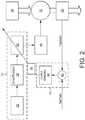
- FIG. 2 shows a block diagram of a fluid temperature control assembly according to an embodiment of the invention.
- RF energy is used to heat the cooling fluid.
- the fluid 30 passes through an electromagnetic heating chamber 32.
- An RF energy source 34 comprises an oscillator 36, a driver circuit 38 and a power amplifier 40.
- a control arrangement 18 comprises a signal comparison arrangement 42 and control circuitry 44.
- An impedance matching network 46 is coupled between the power stage 40 and the electromagnetic heating chamber 32.
- the oscillator 36 produces a carrier wave at the fundamental frequency of excitation for the RF energy source.
- the driver circuit 38 increases the power and optionally selects any one of the harmonics available before being fed to the power stage 40.
- the RF energy is coupled to the heating chamber 32 through the impedance matching network 46 which ensures the RF energy is transmitted efficiently, minimizing standing wave reflections which would otherwise cause parasitic heating in the power amplifier stage 40.
- the temperature of the fluid which has passed through the heating chamber 32 is monitored by the sensor 22.
- the sensor preferably has a fast reaction to changes in temperature.
- Thermistor or Pt1000 devices may be suitable, for example.
- the measured temperature is compared with the system setpoint by comparison arrangement 42 and any differences are fed through an electronic compensation network of control circuitry 44 to derive a gain control signal 48 which modifies the power in the output stage 40 of the RF energy source 34.
- the compensation network is chosen to control the speed of response and stability of the temperature control feedback loop.
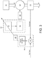
- FIG. 3 illustrates a further embodiment of a fluid temperature control assembly for use in an embodiment of the invention.
- the cooling fluid is heated using microwave energy.
- the microwave energy source 50 comprises an anode current or electromagnet coil driver 52 coupled to a magnetron 54. Microwaves are coupled from the magnetron 52 to the electromagnetic heating chamber 32 by a waveguide 56.
- the control arrangement 18 used to implement feedback control of gain signal 48 may be similar to that described in relation to the embodiment of Figure 2 .
- control assembly depicted in Figure 3 is particularly suitable for use with fluids that respond to higher frequency RF energy. It may use a cavity magnetron 54 similar to the devices normally used in domestic microwave ovens.
- the frequency of the microwave energy is fixed by the design of the microwave cavity within the magnetron 54, but the amount of power available can be varied through control of the average anode current by either pulse or peak control circuitry or by varying the magnetic field strength around the magnetron body.
- a setpoint temperature and maintaining a fluid at a setpoint temperature, this refers to a temperature within a tolerance range around a specific temperature. Depending on the accuracy required, the tolerance range may be ⁇ 0.01°C or as small as ⁇ 0.001°C for example.
Landscapes
- Engineering & Computer Science (AREA)
- Mechanical Engineering (AREA)
- Physics & Mathematics (AREA)
- General Physics & Mathematics (AREA)
- Automation & Control Theory (AREA)
- Remote Sensing (AREA)
- Control Of Temperature (AREA)
Claims (12)
- Fluidtemperaturregulieranordnung (12) in Kombination mit einer Werkzeugmaschine (2), wobei die Anordnung zum Einstellen der Temperatur eines Fluids, das an die Werkzeugmaschine geliefert wird, angeordnet ist, um das Fluid bei einer Solltemperatur an einer Stelle stromabwärts von der Anordnung zu halten, und die Anordnung Folgendes umfasst;
einen Fluideinlass (14) zum Aufnehmen einer Strömung des Fluids bei einer Temperatur unterhalb der Solltemperatur;
einen Fluidauslass (16) zum Abgeben des Fluids;
eine Fluidleitungsanordnung (20), die an den Fluidauslass angeschlossen ist, um das Fluid zu der Werkzeugmaschine (2) zu befördern;
eine Temperatursensoranordnung (22) zum Ausgeben eines Temperatursignals, das auf die Temperatur des Fluids an der stromabwärts gelegenen Stelle anspricht; und
eine Regulieranordnung (18), die zum Aufnehmen des Temperatursignals konfiguriert ist,
dadurch gekennzeichnet, dass
die Anordnung eine Radiofrequenz- (RF-) oder Mikrowellenenergiequelle (34, 50) enthält zum Liefern von Energie an das Fluid, während es durch die Anordnung hindurchgeht, um das Fluid zu erwärmen, und die Regulieranordnung zum Regulieren der Energiequelle mit Bezug auf das Temperatursignal konfiguriert ist, um das Fluid zu erwärmen, um das Fluid bei der Solltemperatur an der stromabwärts gelegenen Stelle zu halten. - Kombination nach Anspruch 1, wobei die RF-Energie mit dem Fluid über eine Impedanzangleichungsanordnung (46) verbunden ist.
- Kombination nach Anspruch 1 oder Anspruch 2, wobei die stromabwärts gelegene Stelle neben dem Fluidauslass (16) liegt.
- Kombination nach Anspruch 1 oder Anspruch 2, wobei die stromabwärts gelegene Stelle im Weg des Fluids von der Anordnung (12) zu der Werkzeugmaschine (2) gelegen ist.
- Kombination nach Anspruch 1 oder Anspruch 2, wobei die stromabwärts gelegene Stelle im Weg des Fluids, das die Werkzeugmaschine (2) verlässt, gelegen ist.
- Kombination nach Anspruch 5, wobei die Regulieranordnung konfiguriert ist, ein weiteres Temperatursignal aufzunehmen, das auf die Temperatur des Fluids im Weg des Fluids von der Anordnung (12) zu der Werkzeugmaschine (2) anspricht, und die Energiequelle ebenfalls unter Bezugnahme auf das weitere Temperatursignal zu regulieren.
- Kombination irgendeines vorhergehenden Anspruchs, wobei die Regulieranordnung (12) zum Aufnehmen eines Eingabesignals, das auf einen Bedienungsparameter der Werkzeugmaschine (2) anspricht, und zum Einstellen der Solltemperatur unter Bezugnahme auf das Eingabesignal konfiguriert ist.
- Werkzeugmaschinensystem, das eine Kombination irgendeines vorhergehenden Anspruchs enthält, wobei das Fluid von der Werkzeugmaschine (2) zurück zu dem Fluideinlass (14) der Anordnung geführt wird.
- Kombination nach einem der Ansprüche 1 bis 7 oder System nach Anspruch 8, die/das eine Kühlanordnung (8) enthält, die zum Kühlen des Fluids auf eine Temperatur unterhalb der Solltemperatur, bevor es zum Fluideinlass (14) der Anordnung (2) geführt wird, konfiguriert ist.
- Kombination oder System nach Anspruch 9, wobei die Kühlanordnung (8) einen Wärmetauscher umfasst.
- Kombination nach einem der Ansprüche 1 bis 7, 9 oder 10 oder System nach einem der Ansprüche 8 bis 10, die/das eine Fluid unter Druck setzende Anordnung (10) zum Erhöhen des Drucks des Fluids, das durch die Kühlanordnung (8) geliefert wird, bevor es zu dem Fuideinlass (14) der Anordnung (12) geführt wird, enthält.
- Verfahren zum Einstellen der Temperatur eines Fluids, das zu einer Werkzeugmaschine (2) geliefert wird, um das Fluid bei einer Solltemperatur an einer vorbestimmten Stelle zu halten, umfassend die Schritte des:Aufnehmens einer Strömung des Fluids bei einer Temperatur unterhalb der Solltemperatur;Erwärmens der Fluidströmung; undFührens der Fluidströmung zu der Werkzeugmaschine,wobei das Fluid im Erwärmungsschritt derart erwärmt wird, dass die Solltemperatur an der vorbestimmten Stelle aufrechterhalten wird,gekennzeichnet durchErwärmen des Fluids im Erwärmungsschritt unter Anwendung von Radiofrequenz- (RF-) oder Mikrowellenenergie.
Applications Claiming Priority (2)
| Application Number | Priority Date | Filing Date | Title |
|---|---|---|---|
| GB1503019.0A GB2535707A (en) | 2015-02-24 | 2015-02-24 | Machine tools and methods of operation thereof |
| PCT/GB2016/050433 WO2016135459A1 (en) | 2015-02-24 | 2016-02-22 | Machine tools and methods of operation thereof |
Publications (2)
| Publication Number | Publication Date |
|---|---|
| EP3262476A1 EP3262476A1 (de) | 2018-01-03 |
| EP3262476B1 true EP3262476B1 (de) | 2019-05-01 |
Family
ID=52822051
Family Applications (1)
| Application Number | Title | Priority Date | Filing Date |
|---|---|---|---|
| EP16706425.2A Active EP3262476B1 (de) | 2015-02-24 | 2016-02-22 | Werkzeugmaschinen und deren betriebsverfahren |
Country Status (4)
| Country | Link |
|---|---|
| US (1) | US10338612B2 (de) |
| EP (1) | EP3262476B1 (de) |
| GB (1) | GB2535707A (de) |
| WO (1) | WO2016135459A1 (de) |
Cited By (1)
| Publication number | Priority date | Publication date | Assignee | Title |
|---|---|---|---|---|
| US12290893B2 (en) | 2019-11-01 | 2025-05-06 | Fives Landis Limited | Temperature control in machine tools |
Families Citing this family (4)
| Publication number | Priority date | Publication date | Assignee | Title |
|---|---|---|---|---|
| TWI628035B (zh) * | 2017-08-09 | 2018-07-01 | 財團法人工業技術研究院 | 熱穩定控制系統與方法 |
| JP6603288B2 (ja) * | 2017-10-25 | 2019-11-06 | ファナック株式会社 | 工作機械の切削液供給装置 |
| CN117500634A (zh) * | 2021-07-01 | 2024-02-02 | Dmg森精机株式会社 | 机床、控制方法以及控制程序 |
| CN117075662B (zh) * | 2023-08-25 | 2024-09-10 | 扬州智能科技有限公司 | 一种自动化机房监控报警系统 |
Family Cites Families (14)
| Publication number | Priority date | Publication date | Assignee | Title |
|---|---|---|---|---|
| US1873769A (en) | 1931-03-03 | 1932-08-23 | Harry J Lang | Fluid temperature control |
| US4324965A (en) * | 1979-07-25 | 1982-04-13 | Hermann Berstorff Maschinenbau Gmbh | Microwave heating method and apparatus including adjustable tuning members |
| JP4626000B2 (ja) * | 1999-12-14 | 2011-02-02 | ダイキン工業株式会社 | 液体冷却装置の温度制御装置 |
| US6827142B2 (en) | 2000-04-27 | 2004-12-07 | Innoventor Engineering, Inc. | Process and apparatus for achieving precision temperature control |
| US6448537B1 (en) * | 2000-12-11 | 2002-09-10 | Eric Anton Nering | Single-wafer process chamber thermal convection processes |
| US7225864B2 (en) * | 2001-02-08 | 2007-06-05 | Oriol Inc. | Multi-channel temperature control system for semiconductor processing facilities |
| DE10328007A1 (de) * | 2003-06-21 | 2005-01-13 | Infineon Technologies Ag | Strukturiertes Halbleiterelement zur Reduzierung von Chargingeffekten |
| US7707841B2 (en) * | 2004-12-14 | 2010-05-04 | Northrop Grumman Ship Systems, Inc. | Phase cooling method and apparatus |
| US8114321B2 (en) | 2005-02-14 | 2012-02-14 | Moldcool International, Llc | Method and apparatus for thermally controlling a mold, die, or injection barrel |
| US7845308B1 (en) * | 2005-10-26 | 2010-12-07 | Lam Research Corporation | Systems incorporating microwave heaters within fluid supply lines of substrate processing chambers and methods for use of such systems |
| JP4875714B2 (ja) | 2006-12-27 | 2012-02-15 | オリオン機械株式会社 | 精密温度調整装置 |
| US8820199B2 (en) * | 2007-09-21 | 2014-09-02 | Air Products And Chemicals, Inc. | Apparatus and method for machining polymers with controlled croygenic cooling |
| JP2009097750A (ja) * | 2007-10-15 | 2009-05-07 | Orion Mach Co Ltd | 精密温度調整装置 |
| WO2012110859A1 (en) * | 2011-02-17 | 2012-08-23 | Meiban International Pte. Ltd. | Micro-temperature controller |
-
2015
- 2015-02-24 GB GB1503019.0A patent/GB2535707A/en not_active Withdrawn
-
2016
- 2016-02-22 WO PCT/GB2016/050433 patent/WO2016135459A1/en not_active Ceased
- 2016-02-22 US US15/549,229 patent/US10338612B2/en active Active
- 2016-02-22 EP EP16706425.2A patent/EP3262476B1/de active Active
Non-Patent Citations (1)
| Title |
|---|
| None * |
Cited By (1)
| Publication number | Priority date | Publication date | Assignee | Title |
|---|---|---|---|---|
| US12290893B2 (en) | 2019-11-01 | 2025-05-06 | Fives Landis Limited | Temperature control in machine tools |
Also Published As
| Publication number | Publication date |
|---|---|
| GB201503019D0 (en) | 2015-04-08 |
| EP3262476A1 (de) | 2018-01-03 |
| US10338612B2 (en) | 2019-07-02 |
| US20180039293A1 (en) | 2018-02-08 |
| WO2016135459A1 (en) | 2016-09-01 |
| GB2535707A (en) | 2016-08-31 |
Similar Documents
| Publication | Publication Date | Title |
|---|---|---|
| US10338612B2 (en) | Machine tools and methods of operation thereof | |
| JP5203612B2 (ja) | プラズマ処理装置 | |
| KR101801070B1 (ko) | 펄스화된 열 전달 유체 흐름을 이용한 플라즈마 프로세싱 장치에서의 온도 제어 | |
| Bora et al. | Magnetothermal instability with generalized Ohm’s law | |
| EP3131104B1 (de) | Kühlung eines statischen elektrischen einlasssystems | |
| JP6112725B2 (ja) | 物質の状態の測定、検出方法及び検出装置 | |
| Wang et al. | Heat transfer correlation models for electrospray evaporative cooling chambers of different geometry types | |
| WO2009017605A1 (en) | System and method for cooling a heat-generating device | |
| Khatak et al. | Enhancement in cooling of electronic components by nanofluids | |
| US20100163221A1 (en) | Local control of heat flow to more accurately regulate machine temperatures | |
| KR20230141544A (ko) | 반도체 제조 장치를 위한 온도 조절 장치, 및 반도체 제조 시스템 | |
| Cao et al. | Pulsed power supply superposed with radio frequency oscillating wave for the improvement of micro-electrical discharge machining process | |
| CN114616074B (zh) | 机床中的温度控制 | |
| Sung et al. | Fast, hot electron production and ion acceleration in a helicon inductive plasma | |
| Oh et al. | Design of a drilling torque controller for a machining center | |
| US20030091487A1 (en) | Continuous flow heating system | |
| Knauf et al. | Low frequency induction heating for the sealing of plastic microfluidic systems | |
| Wang et al. | A highly efficient integrated silicon-microchannel cooler for multi-module electronic microsystems: model design, optimization, and performance validation | |
| US20190288303A1 (en) | Thermal regulation system for a fuel cell | |
| KR101631768B1 (ko) | 스핀들 온도 조절 장치 | |
| Correia et al. | Practical implementation and validation of a novel process for manufacturing milling tools using adhesive bonding | |
| Kim et al. | Hot roller embossing system equipped with a temperature margin-based controller | |
| Ng et al. | Neutral penetration in centrifugally confined plasmas | |
| EP4431222B1 (de) | Prädiktive kühlung für eine laserbearbeitungsvorrichtung | |
| Fan et al. | Design and control of a thermal actuation system." |
Legal Events
| Date | Code | Title | Description |
|---|---|---|---|
| STAA | Information on the status of an ep patent application or granted ep patent |
Free format text: STATUS: THE INTERNATIONAL PUBLICATION HAS BEEN MADE |
|
| PUAI | Public reference made under article 153(3) epc to a published international application that has entered the european phase |
Free format text: ORIGINAL CODE: 0009012 |
|
| STAA | Information on the status of an ep patent application or granted ep patent |
Free format text: STATUS: REQUEST FOR EXAMINATION WAS MADE |
|
| 17P | Request for examination filed |
Effective date: 20170608 |
|
| AK | Designated contracting states |
Kind code of ref document: A1 Designated state(s): AL AT BE BG CH CY CZ DE DK EE ES FI FR GB GR HR HU IE IS IT LI LT LU LV MC MK MT NL NO PL PT RO RS SE SI SK SM TR |
|
| AX | Request for extension of the european patent |
Extension state: BA ME |
|
| DAV | Request for validation of the european patent (deleted) | ||
| DAX | Request for extension of the european patent (deleted) | ||
| GRAP | Despatch of communication of intention to grant a patent |
Free format text: ORIGINAL CODE: EPIDOSNIGR1 |
|
| STAA | Information on the status of an ep patent application or granted ep patent |
Free format text: STATUS: GRANT OF PATENT IS INTENDED |
|
| INTG | Intention to grant announced |
Effective date: 20181109 |
|
| GRAS | Grant fee paid |
Free format text: ORIGINAL CODE: EPIDOSNIGR3 |
|
| GRAA | (expected) grant |
Free format text: ORIGINAL CODE: 0009210 |
|
| STAA | Information on the status of an ep patent application or granted ep patent |
Free format text: STATUS: THE PATENT HAS BEEN GRANTED |
|
| AK | Designated contracting states |
Kind code of ref document: B1 Designated state(s): AL AT BE BG CH CY CZ DE DK EE ES FI FR GB GR HR HU IE IS IT LI LT LU LV MC MK MT NL NO PL PT RO RS SE SI SK SM TR |
|
| REG | Reference to a national code |
Ref country code: GB Ref legal event code: FG4D |
|
| REG | Reference to a national code |
Ref country code: CH Ref legal event code: EP Ref country code: AT Ref legal event code: REF Ref document number: 1127769 Country of ref document: AT Kind code of ref document: T Effective date: 20190515 |
|
| REG | Reference to a national code |
Ref country code: DE Ref legal event code: R096 Ref document number: 602016013173 Country of ref document: DE |
|
| REG | Reference to a national code |
Ref country code: IE Ref legal event code: FG4D |
|
| REG | Reference to a national code |
Ref country code: NL Ref legal event code: MP Effective date: 20190501 |
|
| REG | Reference to a national code |
Ref country code: LT Ref legal event code: MG4D |
|
| PG25 | Lapsed in a contracting state [announced via postgrant information from national office to epo] |
Ref country code: ES Free format text: LAPSE BECAUSE OF FAILURE TO SUBMIT A TRANSLATION OF THE DESCRIPTION OR TO PAY THE FEE WITHIN THE PRESCRIBED TIME-LIMIT Effective date: 20190501 Ref country code: NL Free format text: LAPSE BECAUSE OF FAILURE TO SUBMIT A TRANSLATION OF THE DESCRIPTION OR TO PAY THE FEE WITHIN THE PRESCRIBED TIME-LIMIT Effective date: 20190501 Ref country code: FI Free format text: LAPSE BECAUSE OF FAILURE TO SUBMIT A TRANSLATION OF THE DESCRIPTION OR TO PAY THE FEE WITHIN THE PRESCRIBED TIME-LIMIT Effective date: 20190501 Ref country code: LT Free format text: LAPSE BECAUSE OF FAILURE TO SUBMIT A TRANSLATION OF THE DESCRIPTION OR TO PAY THE FEE WITHIN THE PRESCRIBED TIME-LIMIT Effective date: 20190501 Ref country code: HR Free format text: LAPSE BECAUSE OF FAILURE TO SUBMIT A TRANSLATION OF THE DESCRIPTION OR TO PAY THE FEE WITHIN THE PRESCRIBED TIME-LIMIT Effective date: 20190501 Ref country code: SE Free format text: LAPSE BECAUSE OF FAILURE TO SUBMIT A TRANSLATION OF THE DESCRIPTION OR TO PAY THE FEE WITHIN THE PRESCRIBED TIME-LIMIT Effective date: 20190501 Ref country code: NO Free format text: LAPSE BECAUSE OF FAILURE TO SUBMIT A TRANSLATION OF THE DESCRIPTION OR TO PAY THE FEE WITHIN THE PRESCRIBED TIME-LIMIT Effective date: 20190801 Ref country code: PT Free format text: LAPSE BECAUSE OF FAILURE TO SUBMIT A TRANSLATION OF THE DESCRIPTION OR TO PAY THE FEE WITHIN THE PRESCRIBED TIME-LIMIT Effective date: 20190901 Ref country code: AL Free format text: LAPSE BECAUSE OF FAILURE TO SUBMIT A TRANSLATION OF THE DESCRIPTION OR TO PAY THE FEE WITHIN THE PRESCRIBED TIME-LIMIT Effective date: 20190501 |
|
| PG25 | Lapsed in a contracting state [announced via postgrant information from national office to epo] |
Ref country code: LV Free format text: LAPSE BECAUSE OF FAILURE TO SUBMIT A TRANSLATION OF THE DESCRIPTION OR TO PAY THE FEE WITHIN THE PRESCRIBED TIME-LIMIT Effective date: 20190501 Ref country code: RS Free format text: LAPSE BECAUSE OF FAILURE TO SUBMIT A TRANSLATION OF THE DESCRIPTION OR TO PAY THE FEE WITHIN THE PRESCRIBED TIME-LIMIT Effective date: 20190501 Ref country code: GR Free format text: LAPSE BECAUSE OF FAILURE TO SUBMIT A TRANSLATION OF THE DESCRIPTION OR TO PAY THE FEE WITHIN THE PRESCRIBED TIME-LIMIT Effective date: 20190802 Ref country code: BG Free format text: LAPSE BECAUSE OF FAILURE TO SUBMIT A TRANSLATION OF THE DESCRIPTION OR TO PAY THE FEE WITHIN THE PRESCRIBED TIME-LIMIT Effective date: 20190801 |
|
| REG | Reference to a national code |
Ref country code: AT Ref legal event code: MK05 Ref document number: 1127769 Country of ref document: AT Kind code of ref document: T Effective date: 20190501 |
|
| PG25 | Lapsed in a contracting state [announced via postgrant information from national office to epo] |
Ref country code: IS Free format text: LAPSE BECAUSE OF FAILURE TO SUBMIT A TRANSLATION OF THE DESCRIPTION OR TO PAY THE FEE WITHIN THE PRESCRIBED TIME-LIMIT Effective date: 20190901 |
|
| PG25 | Lapsed in a contracting state [announced via postgrant information from national office to epo] |
Ref country code: CZ Free format text: LAPSE BECAUSE OF FAILURE TO SUBMIT A TRANSLATION OF THE DESCRIPTION OR TO PAY THE FEE WITHIN THE PRESCRIBED TIME-LIMIT Effective date: 20190501 Ref country code: RO Free format text: LAPSE BECAUSE OF FAILURE TO SUBMIT A TRANSLATION OF THE DESCRIPTION OR TO PAY THE FEE WITHIN THE PRESCRIBED TIME-LIMIT Effective date: 20190501 Ref country code: SK Free format text: LAPSE BECAUSE OF FAILURE TO SUBMIT A TRANSLATION OF THE DESCRIPTION OR TO PAY THE FEE WITHIN THE PRESCRIBED TIME-LIMIT Effective date: 20190501 Ref country code: AT Free format text: LAPSE BECAUSE OF FAILURE TO SUBMIT A TRANSLATION OF THE DESCRIPTION OR TO PAY THE FEE WITHIN THE PRESCRIBED TIME-LIMIT Effective date: 20190501 Ref country code: EE Free format text: LAPSE BECAUSE OF FAILURE TO SUBMIT A TRANSLATION OF THE DESCRIPTION OR TO PAY THE FEE WITHIN THE PRESCRIBED TIME-LIMIT Effective date: 20190501 Ref country code: DK Free format text: LAPSE BECAUSE OF FAILURE TO SUBMIT A TRANSLATION OF THE DESCRIPTION OR TO PAY THE FEE WITHIN THE PRESCRIBED TIME-LIMIT Effective date: 20190501 |
|
| REG | Reference to a national code |
Ref country code: DE Ref legal event code: R097 Ref document number: 602016013173 Country of ref document: DE |
|
| PG25 | Lapsed in a contracting state [announced via postgrant information from national office to epo] |
Ref country code: IT Free format text: LAPSE BECAUSE OF FAILURE TO SUBMIT A TRANSLATION OF THE DESCRIPTION OR TO PAY THE FEE WITHIN THE PRESCRIBED TIME-LIMIT Effective date: 20190501 Ref country code: SM Free format text: LAPSE BECAUSE OF FAILURE TO SUBMIT A TRANSLATION OF THE DESCRIPTION OR TO PAY THE FEE WITHIN THE PRESCRIBED TIME-LIMIT Effective date: 20190501 |
|
| PLBE | No opposition filed within time limit |
Free format text: ORIGINAL CODE: 0009261 |
|
| STAA | Information on the status of an ep patent application or granted ep patent |
Free format text: STATUS: NO OPPOSITION FILED WITHIN TIME LIMIT |
|
| PG25 | Lapsed in a contracting state [announced via postgrant information from national office to epo] |
Ref country code: TR Free format text: LAPSE BECAUSE OF FAILURE TO SUBMIT A TRANSLATION OF THE DESCRIPTION OR TO PAY THE FEE WITHIN THE PRESCRIBED TIME-LIMIT Effective date: 20190501 |
|
| 26N | No opposition filed |
Effective date: 20200204 |
|
| PG25 | Lapsed in a contracting state [announced via postgrant information from national office to epo] |
Ref country code: PL Free format text: LAPSE BECAUSE OF FAILURE TO SUBMIT A TRANSLATION OF THE DESCRIPTION OR TO PAY THE FEE WITHIN THE PRESCRIBED TIME-LIMIT Effective date: 20190501 |
|
| PG25 | Lapsed in a contracting state [announced via postgrant information from national office to epo] |
Ref country code: SI Free format text: LAPSE BECAUSE OF FAILURE TO SUBMIT A TRANSLATION OF THE DESCRIPTION OR TO PAY THE FEE WITHIN THE PRESCRIBED TIME-LIMIT Effective date: 20190501 |
|
| REG | Reference to a national code |
Ref country code: CH Ref legal event code: PL |
|
| REG | Reference to a national code |
Ref country code: BE Ref legal event code: MM Effective date: 20200229 |
|
| PG25 | Lapsed in a contracting state [announced via postgrant information from national office to epo] |
Ref country code: LU Free format text: LAPSE BECAUSE OF NON-PAYMENT OF DUE FEES Effective date: 20200222 Ref country code: MC Free format text: LAPSE BECAUSE OF FAILURE TO SUBMIT A TRANSLATION OF THE DESCRIPTION OR TO PAY THE FEE WITHIN THE PRESCRIBED TIME-LIMIT Effective date: 20190501 |
|
| PG25 | Lapsed in a contracting state [announced via postgrant information from national office to epo] |
Ref country code: LI Free format text: LAPSE BECAUSE OF NON-PAYMENT OF DUE FEES Effective date: 20200229 Ref country code: CH Free format text: LAPSE BECAUSE OF NON-PAYMENT OF DUE FEES Effective date: 20200229 |
|
| PG25 | Lapsed in a contracting state [announced via postgrant information from national office to epo] |
Ref country code: IE Free format text: LAPSE BECAUSE OF NON-PAYMENT OF DUE FEES Effective date: 20200222 |
|
| PG25 | Lapsed in a contracting state [announced via postgrant information from national office to epo] |
Ref country code: BE Free format text: LAPSE BECAUSE OF NON-PAYMENT OF DUE FEES Effective date: 20200229 |
|
| PG25 | Lapsed in a contracting state [announced via postgrant information from national office to epo] |
Ref country code: MT Free format text: LAPSE BECAUSE OF FAILURE TO SUBMIT A TRANSLATION OF THE DESCRIPTION OR TO PAY THE FEE WITHIN THE PRESCRIBED TIME-LIMIT Effective date: 20190501 Ref country code: CY Free format text: LAPSE BECAUSE OF FAILURE TO SUBMIT A TRANSLATION OF THE DESCRIPTION OR TO PAY THE FEE WITHIN THE PRESCRIBED TIME-LIMIT Effective date: 20190501 |
|
| PG25 | Lapsed in a contracting state [announced via postgrant information from national office to epo] |
Ref country code: MK Free format text: LAPSE BECAUSE OF FAILURE TO SUBMIT A TRANSLATION OF THE DESCRIPTION OR TO PAY THE FEE WITHIN THE PRESCRIBED TIME-LIMIT Effective date: 20190501 |
|
| PGFP | Annual fee paid to national office [announced via postgrant information from national office to epo] |
Ref country code: GB Payment date: 20260121 Year of fee payment: 11 |
|
| PGFP | Annual fee paid to national office [announced via postgrant information from national office to epo] |
Ref country code: DE Payment date: 20260121 Year of fee payment: 11 |
|
| PGFP | Annual fee paid to national office [announced via postgrant information from national office to epo] |
Ref country code: FR Payment date: 20260121 Year of fee payment: 11 |