EP3261520B1 - Dispositif de détection de fréquence cardiaque et de variabilité de fréquence cardiaque - Google Patents
Dispositif de détection de fréquence cardiaque et de variabilité de fréquence cardiaque Download PDFInfo
- Publication number
- EP3261520B1 EP3261520B1 EP16707210.7A EP16707210A EP3261520B1 EP 3261520 B1 EP3261520 B1 EP 3261520B1 EP 16707210 A EP16707210 A EP 16707210A EP 3261520 B1 EP3261520 B1 EP 3261520B1
- Authority
- EP
- European Patent Office
- Prior art keywords
- sensor
- measurement signal
- heartbeats
- heart rate
- subject
- Prior art date
- Legal status (The legal status is an assumption and is not a legal conclusion. Google has not performed a legal analysis and makes no representation as to the accuracy of the status listed.)
- Active
Links
- 238000000034 method Methods 0.000 claims description 73
- 230000033001 locomotion Effects 0.000 claims description 48
- 238000005259 measurement Methods 0.000 claims description 37
- 238000012545 processing Methods 0.000 claims description 24
- 238000001514 detection method Methods 0.000 claims description 18
- 238000004458 analytical method Methods 0.000 claims description 3
- 230000004044 response Effects 0.000 claims description 3
- 230000035487 diastolic blood pressure Effects 0.000 claims description 2
- 230000001747 exhibiting effect Effects 0.000 claims 2
- 230000008569 process Effects 0.000 description 21
- 210000003491 skin Anatomy 0.000 description 19
- 238000004891 communication Methods 0.000 description 17
- 230000006870 function Effects 0.000 description 13
- 230000008859 change Effects 0.000 description 8
- 230000000694 effects Effects 0.000 description 8
- 230000003936 working memory Effects 0.000 description 8
- 230000003287 optical effect Effects 0.000 description 7
- 238000010586 diagram Methods 0.000 description 6
- 230000015654 memory Effects 0.000 description 6
- 230000005540 biological transmission Effects 0.000 description 5
- 238000013461 design Methods 0.000 description 5
- 238000004422 calculation algorithm Methods 0.000 description 4
- 238000004590 computer program Methods 0.000 description 4
- 238000001914 filtration Methods 0.000 description 4
- 230000000670 limiting effect Effects 0.000 description 4
- 238000012937 correction Methods 0.000 description 3
- 238000009434 installation Methods 0.000 description 3
- 230000037081 physical activity Effects 0.000 description 3
- 210000000434 stratum corneum Anatomy 0.000 description 3
- 230000009471 action Effects 0.000 description 2
- 230000036772 blood pressure Effects 0.000 description 2
- 230000007211 cardiovascular event Effects 0.000 description 2
- 230000003292 diminished effect Effects 0.000 description 2
- 238000007667 floating Methods 0.000 description 2
- 238000012986 modification Methods 0.000 description 2
- 230000004048 modification Effects 0.000 description 2
- 238000013186 photoplethysmography Methods 0.000 description 2
- 230000035945 sensitivity Effects 0.000 description 2
- RYGMFSIKBFXOCR-UHFFFAOYSA-N Copper Chemical compound [Cu] RYGMFSIKBFXOCR-UHFFFAOYSA-N 0.000 description 1
- 241000282412 Homo Species 0.000 description 1
- 241000124008 Mammalia Species 0.000 description 1
- 230000001133 acceleration Effects 0.000 description 1
- 230000002238 attenuated effect Effects 0.000 description 1
- 238000010009 beating Methods 0.000 description 1
- 230000000903 blocking effect Effects 0.000 description 1
- 210000004204 blood vessel Anatomy 0.000 description 1
- 238000004364 calculation method Methods 0.000 description 1
- 230000000747 cardiac effect Effects 0.000 description 1
- 230000010267 cellular communication Effects 0.000 description 1
- 230000006835 compression Effects 0.000 description 1
- 238000007906 compression Methods 0.000 description 1
- 239000000470 constituent Substances 0.000 description 1
- 238000010276 construction Methods 0.000 description 1
- 230000006837 decompression Effects 0.000 description 1
- 230000003247 decreasing effect Effects 0.000 description 1
- 230000001419 dependent effect Effects 0.000 description 1
- 210000000613 ear canal Anatomy 0.000 description 1
- 238000005516 engineering process Methods 0.000 description 1
- 239000000835 fiber Substances 0.000 description 1
- 230000036541 health Effects 0.000 description 1
- 238000007689 inspection Methods 0.000 description 1
- 238000012806 monitoring device Methods 0.000 description 1
- 230000002829 reductive effect Effects 0.000 description 1
- 230000002441 reversible effect Effects 0.000 description 1
- 238000012552 review Methods 0.000 description 1
- 238000005070 sampling Methods 0.000 description 1
- 230000011664 signaling Effects 0.000 description 1
- 238000001228 spectrum Methods 0.000 description 1
- 239000000126 substance Substances 0.000 description 1
- 239000004753 textile Substances 0.000 description 1
- 230000009466 transformation Effects 0.000 description 1
- 230000001052 transient effect Effects 0.000 description 1
- 210000000707 wrist Anatomy 0.000 description 1
Images

Classifications
-
- A—HUMAN NECESSITIES
- A61—MEDICAL OR VETERINARY SCIENCE; HYGIENE
- A61B—DIAGNOSIS; SURGERY; IDENTIFICATION
- A61B5/00—Measuring for diagnostic purposes; Identification of persons
- A61B5/72—Signal processing specially adapted for physiological signals or for diagnostic purposes
- A61B5/7203—Signal processing specially adapted for physiological signals or for diagnostic purposes for noise prevention, reduction or removal
- A61B5/7207—Signal processing specially adapted for physiological signals or for diagnostic purposes for noise prevention, reduction or removal of noise induced by motion artifacts
-
- A—HUMAN NECESSITIES
- A61—MEDICAL OR VETERINARY SCIENCE; HYGIENE
- A61B—DIAGNOSIS; SURGERY; IDENTIFICATION
- A61B5/00—Measuring for diagnostic purposes; Identification of persons
- A61B5/02—Detecting, measuring or recording pulse, heart rate, blood pressure or blood flow; Combined pulse/heart-rate/blood pressure determination; Evaluating a cardiovascular condition not otherwise provided for, e.g. using combinations of techniques provided for in this group with electrocardiography or electroauscultation; Heart catheters for measuring blood pressure
- A61B5/024—Detecting, measuring or recording pulse rate or heart rate
- A61B5/02416—Detecting, measuring or recording pulse rate or heart rate using photoplethysmograph signals, e.g. generated by infrared radiation
-
- A—HUMAN NECESSITIES
- A61—MEDICAL OR VETERINARY SCIENCE; HYGIENE
- A61B—DIAGNOSIS; SURGERY; IDENTIFICATION
- A61B5/00—Measuring for diagnostic purposes; Identification of persons
- A61B5/02—Detecting, measuring or recording pulse, heart rate, blood pressure or blood flow; Combined pulse/heart-rate/blood pressure determination; Evaluating a cardiovascular condition not otherwise provided for, e.g. using combinations of techniques provided for in this group with electrocardiography or electroauscultation; Heart catheters for measuring blood pressure
- A61B5/024—Detecting, measuring or recording pulse rate or heart rate
- A61B5/02405—Determining heart rate variability
-
- A—HUMAN NECESSITIES
- A61—MEDICAL OR VETERINARY SCIENCE; HYGIENE
- A61B—DIAGNOSIS; SURGERY; IDENTIFICATION
- A61B5/00—Measuring for diagnostic purposes; Identification of persons
- A61B5/02—Detecting, measuring or recording pulse, heart rate, blood pressure or blood flow; Combined pulse/heart-rate/blood pressure determination; Evaluating a cardiovascular condition not otherwise provided for, e.g. using combinations of techniques provided for in this group with electrocardiography or electroauscultation; Heart catheters for measuring blood pressure
- A61B5/024—Detecting, measuring or recording pulse rate or heart rate
- A61B5/0245—Detecting, measuring or recording pulse rate or heart rate by using sensing means generating electric signals, i.e. ECG signals
-
- A—HUMAN NECESSITIES
- A61—MEDICAL OR VETERINARY SCIENCE; HYGIENE
- A61B—DIAGNOSIS; SURGERY; IDENTIFICATION
- A61B5/00—Measuring for diagnostic purposes; Identification of persons
- A61B5/05—Detecting, measuring or recording for diagnosis by means of electric currents or magnetic fields; Measuring using microwaves or radio waves
- A61B5/053—Measuring electrical impedance or conductance of a portion of the body
- A61B5/0531—Measuring skin impedance
-
- A—HUMAN NECESSITIES
- A61—MEDICAL OR VETERINARY SCIENCE; HYGIENE
- A61B—DIAGNOSIS; SURGERY; IDENTIFICATION
- A61B5/00—Measuring for diagnostic purposes; Identification of persons
- A61B5/68—Arrangements of detecting, measuring or recording means, e.g. sensors, in relation to patient
- A61B5/6801—Arrangements of detecting, measuring or recording means, e.g. sensors, in relation to patient specially adapted to be attached to or worn on the body surface
- A61B5/6802—Sensor mounted on worn items
- A61B5/681—Wristwatch-type devices
-
- A—HUMAN NECESSITIES
- A61—MEDICAL OR VETERINARY SCIENCE; HYGIENE
- A61B—DIAGNOSIS; SURGERY; IDENTIFICATION
- A61B2560/00—Constructional details of operational features of apparatus; Accessories for medical measuring apparatus
- A61B2560/02—Operational features
- A61B2560/0204—Operational features of power management
- A61B2560/0209—Operational features of power management adapted for power saving
Definitions
- the present disclosure relates to methods and apparatuses for detecting heart rate and/or heart rate variability.
- Heart rate (HR) and heart rate variability (HRV) are measurable quantities that help to assess the health and/or fitness of a living subject.
- HRV measurements may be used in the detection of stress in humans.
- One device used to measure or obtain these parameters is a photoplethysmograph (PPG), which illuminates skin and detects changes in skin volume by inspecting transmitted or reflected light. Changes in volume caused by skin or blood vessels being enlarged or shrunk by heart beats can be measured to detect the heart beats.
- the HR and/or HRV can be determined from the detection of heart beats and intervals between heart beats, sometimes referred to as an inter-beat interval (IBI).
- IBI inter-beat interval
- PPG devices can be relatively compact, and can be portable or can be worn by an individual subject.
- Artifacts may also be countered with the use of accelerometers that can detect motion of the PPG device and provide compensation estimates for signals obtained from the PPG device.
- use of one or more accelerometers to detect motion for motion artifact compensation tends to increase cost, size and power consumption of the overall device.
- SC skin conductance
- An SC-based device measures electrical characteristics of an area of skin to determine various quantities of interest, including HR and/or HRV. For example, during physical activity, SC is attenuated by the beating of the heart, which permits detection of HR and/or HRV.
- SC devices sometimes encounter accuracy challenges in the absence of physical activity.
- WO 2014/147024 A1 discloses an apparatus for electrodermal activity measurement with current compensation.
- the apparatus for measuring electrodermal activity can include a first electrode in contact with a first portion and a second electrode in contact with a second portion of a stratum corneum.
- a processing module is electrically coupled to the electrodes and is operable to (a) bias the first electrode at a first voltage V+ and the second electrode at a second voltage V- (b) measure a current flowing between the first electrode and the second electrode, the current corresponding to the conductance of the stratum corneum, (c) subtract a compensation current from the measured current (d) measure a resulting current producing an amplified output voltage (e) measure a conductance of the stratum corneum, and (f) adjust at least one of the first voltage, the second voltage and the compensation current to desaturate the output voltage.
- US 2010/268056 A1 discloses a washable wearable biosensor.
- the textile, wearable device can support integrated photoplethysmography, skin conductance, motion, and temperature sensors in a small wearable package.
- US 2008/165017 A1 discloses an ear-mounted biosensor.
- the proposed physiological monitoring device includes a device housing shaped to fit behind an ear of a subject and a sensor attached to the device housing so as to sense a physiological characteristic of the subject at a location behind the ear.
- An earphone speaker is directed towards an ear canal of the subject and provides an audible communication to the subject responsively to the physiological characteristic.
- EP 2 696 754 A1 discloses a stress measuring device and method.
- US 2014/094675 A1 discloses arrayed electrodes in a wearable device for determining physiological characteristics.
- US 2012/123232 A1 discloses a method and apparatus for determining heart rate variability using wavelet transformation.
- the techniques and implementations discussed herein relate to methods and apparatuses for sensing cardiac or cardiovascular events in a subject entity.
- detection and/or measurement of heartbeats, heart rate (HR) and/or heart rate variability (HRV) is discussed.
- One or more sensors or sensing techniques are employed to detect and/or measure these quantities, and the sensor(s) may be wearable and/or portable.
- the sensor(s) may operate using a limited power source, such as one or more batteries, a solar energy power source, or any other type of portable or wearable power source.
- the sensors and/or sensing techniques may operate on different principles and may include different power profiles.
- the sensors and/or sensing techniques may be used at the same time or at different times that may overlap partially or completely, or may be mutually exclusive.
- a controller is employed to provide communication and/or control functions for the sensors and/or sensing techniques.
- the controller may be implemented as a processor that accesses instructions from storage and executes the instructions to carry out communication and/or control functions.
- the controller may be analog or digital and may include a number of components such as storage, input/output control and/or management, one or more central processing units and/or arithmetic processing units, a communication interface, a user interface, and may include other components that contribute to implementing methods and/or apparatuses in accordance with the present disclosure.
- the controller may be sufficiently small to be portable or worn by an individual.
- the methods and/or apparatuses according to the present disclosure may be implemented with a wearable device for detecting HR and/or HRV
- the device may be worn on an appendage of the subject, such as on a human wrist.
- the device includes one or more photoplethysmograph (PPG) sensors and/or one or more skin conductance (SC) sensors.
- PPG sensor(s) and/or SC sensor(s) may have ranges of operation that are the same, at least partially overlapping and/or mutually exclusive or nonoverlapping, for the same or different types of sensors collectively.
- one or more PPG sensors are used to detect heartbeats during periods of low activity of the subject.
- one or more SC sensors are used to detect heartbeats during high activity periods of the subject.
- the PPG sensor may consume more energy than the SC sensor during active heartbeat detection.
- the controller controls the PPG sensor(s) and/or the SC sensor(s) to detect HR and/or HRV over different ranges of physical activity or conditions of a subject being monitored by the sensor(s). For example the controller may turn on or turn off one or more sensors.
- the controller may provide signaling to the sensor(s) to cause the sensors to change their range of operation, for example by causing the sensor(s) to be more or less sensitive to certain phenomena that may impact detection of HR and/or HRV
- the controller uses the data obtained from the sensor(s) to determine HR and/or HRV, and so selectively uses data from one or more sensors.
- the selection of data from one or more sensors may include turning a sensor on or off, putting a sensor in a lower or higher power mode, blocking or receiving data from a sensor, applying different algorithms to condition or analyze data from a sensor, or any other action that causes data to be selectively obtained from one or more sensors.
- the selection of data from one or more sensors is based on signal quality of the signals provided by the sensor(s). Other criteria for selection may be derived from other sources, such as one or more accelerometers, time of day, table lookup or algorithm application for sensor signals with certain characteristics, and any other source that may indicate a preference for a certain sensing technique or a sensor to obtain useful data to detect or determine HR and/or HRV.
- an accelerometer may be used or not.
- an accelerometer may be present in an embodiment of the disclosed apparatus or not, or may be present and turned on or off.
- an accelerometer is not used to switch sensors or to reduce motion artifacts.
- the controller may execute instructions (software), in accordance with an algorithm, to assess signal quality from a given sensor and may select one sensor over the other to measure heartbeats.
- the controller may also or otherwise control sensor usage or implement sensing techniques to reduce battery power consumption.
- the disclosed methods and/or apparatuses may measure SC with relatively high precision and/or at a relatively high rate.
- An SC sensor may include skin sensing electronics, an anti-aliasing filter and/or a balanced floating design.
- the controller and/or SC sensor may include filtering of the raw sensor signal, and may include a digital filter for the analog to digital converter output.
- a signal is obtained from the SC sensor that yields a waveform from which peaks caused by the heartbeats can be extracted by analyzing the waveform ripple.
- HR and/or HRV may be obtained from the timestamps of the peaks.
- An SC sensor is shown in European patent application no. 14 18 6956 .
- the data related to HR and/or HRV may be stored, for example using a micro SD card, and/or may be transmitted, for example via a Bluetooth link, to a receiving station such as a mobile phone or other communication/network device.
- the present disclosure also relates to an apparatus for performing the operations herein.
- This apparatus may be specially constructed for the required purposes, or it may comprise a general-purpose computer selectively activated or reconfigured by a computer program stored in the computer.
- a computer program may be stored in a computer readable storage medium, such as, but is not limited to, any type of disk including floppy disks, optical disks, CD-ROMs, magnetic-optical disks, read-only memories (ROMs), random access memories (RAMs), EPROMs, EEPROMs, magnetic or optical cards, application specific integrated circuits (ASICs), or any type of media suitable for storing electronic instructions, and each may be coupled to a computer system bus.
- the computers referred to in the specification may include a single processor or may be architectures employing multiple processor designs for increased computing capability.
- the present disclosure relates to sensors and/or sensing techniques for detecting heart rate (HR) and/or heart rate variability (HRV).
- HR heart rate
- HRV heart rate variability
- Some embodiments of the present disclosure use multiple sensors and/or sensing techniques for sensing heartbeats, which may be used to determine HR and/or HRV
- one or more skin conductance (SC) sensors are employed, and may be used with one or more photoplethysmograph (PPG) sensors to detect and/or measure heartbeats and/or heart inter-beat intervals of a living subject, such as a mammal, including a human.
- SC skin conductance
- PPG photoplethysmograph
- the disclosed methods and apparatuses may be implemented by attachments to a subject's body, including implementation as bands around an appendage, such as wristbands for a human.
- the methods and apparatuses may be implemented with electronics and/or software, and may be optimized for accurately measuring inter-beat intervals (IBIs) while minimizing power usage.
- IBIs inter-beat intervals
- SC may be used to detect heartbeats.
- photoplethysmography may be used to detect heartbeats.
- Embodiments discussed herein may alter the operation of one or more sensors to have greater or lesser sensitivity, power usage and/or sensing range.
- the light output, spectrum or sensitivity of one or more PPG sensors may be modified, such as by being decreased or increased, during periods of low activity. Such modifications may be made while maintaining a certain level of accuracy, and/or without loss of accuracy.
- Some embodiments of the present disclosure may include a motion sensor such as, e.g., an accelerometer.
- the motion sensor may be capable of sensing motion in one or more dimensions.
- the motion sensor may be used to capture data that may be used to reduce motion artifacts from PPG HR sensing or measurements.
- Other embodiments may omit such a motion sensor, or forego the use of such a motion sensor.
- a controller may be used to switch from PPG sensing or measurements to SC sensing or measurements when motion artifacts are detected. Motion artifacts may be detected from the signal provided by the PPG sensor.
- the SC sensor is adapted to measure skin conductance response rise times, which are a proxy for sensing blood pressure.
- skin conductance can be used to detect cardiovascular events that can be used to determine blood pressure, including diastolic blood pressure.
- the SC sensor typically samples skin conductance from tens to hundreds of times per second, with an accuracy of less than one nanoSiemens.
- the output of the SC sensor may be filtered with, e.g., a low-pass filter having a cutoff frequency on the order of the sampling rate of the SC sensor.
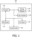
- Device 100 for sensing HR and/or HRV is illustrated in block diagram form.
- Device 100 includes a processor 110, a PPG sensor 112, an SC sensor 114, a storage 116 and a user interface 120.
- Storage 116 may be any type of media that is usable with device 100, and may store software 118.
- Software 118 may include instructions that can be executed by processor 110 to implement HR and/or HRV sensing functions, as well as other functions.
- PPG sensor 112 and SC sensor 114 each may be composed of one or more constituent sensors.
- Device 100 may optionally include an accelerometer 122, which is shown in dashed lines to indicate that it is optional.
- Processor 110 may operate as a controller for PPG sensor 112, SC sensor 114 and/or user interface 120.
- Processor 110 may receive signals from and send signals to PPG sensor 112, SC sensor 114 and/or user interface 120.
- processor 110 may receive raw sensor data from PPG sensor 112 and/or SC sensor 114, and/or may receive signals that represent filtered or processed sensor data from these sensors.
- Processor 110 may store the signals from PPG sensor 112 and/or SC sensor 114 in storage 116.
- Software 118 may be accessed and used by processor 110 to perform the functions desired with respect to controlling PPG sensor 112 and/or SC sensor 114 and/or processing signals or data, including those used in conjunction with storage 116 and/or user interface 120.
- Processor 110 may control PPG sensor 112 and/or SC sensor 114 to achieve various functions, including obtaining sensing data, turning on or off functionality within the sensors or turning the sensors on or off.
- processor 110 may send signals to and receive signals from accelerometer 122.
- the signals received from accelerometer 122 may include raw sensor data and/or filtered or processed sensor data.
- data from accelerometer 122 may be used to cause a switch between sensors or to reduce the impact of motion artifacts.
- Processor 110 can execute software 118 to cause a change in operation of device 100 based on signals received from PPG sensor 112 and/or SC sensor 114 and/or accelerometer 122.
- processor 110 can analyze signals from PPG sensor 112 and determine the presence of motion artifacts or the loss of a reliable signal for determining HR and/or HRV Upon such a determination, processor 110 can disregard signals from PPG sensor 112 in determining HR and/or HRV, and/or can disable output from the sensor, shut PPG sensor 112 off or place it in a low power mode to conserve power.
- Processor 110 may begin using SC sensor 114 as a primary source for signals used to determine HR and/or HRV, which may include turning SC sensor 114 on, enabling an output of the sensor, changing from low power to high power mode, or any other change or switch operation to utilize signals from SC sensor 114 when PPG sensor 112 may provide an unreliable signal.
- SC sensor 114 may include turning SC sensor 114 on, enabling an output of the sensor, changing from low power to high power mode, or any other change or switch operation to utilize signals from SC sensor 114 when PPG sensor 112 may provide an unreliable signal.
- the switching operation undertaken by processor 110 is a controlled change in the operation of device 100 to meet design goals.
- the controlled change may be turning one or more of PPG sensor 112 and/or SC sensor 114 on or off, or putting one or more sensors in a low power mode.
- the controlled change may be selecting which sensor, sensor signal, or sensing technique may be used to detect and/or measure heartbeats.
- the design goals may be obtaining a high degree of reliability, optimized power consumption, or any other goal with respect to desired operation of device 100.
- processor 110 monitors the signals from PPG sensor 112 and/or SC sensor 114 and determines HR and/or HRV from the signals obtained from one or both sensors.
- Processor 110 can determine when the signals from one or more of PPG sensor 112 and/or SC sensor 114 become unreliable for detecting and/or measuring heartbeats, or unreliable for use in calculating HR and/or HRV
- processor 110 can determine when an output signal from PPG sensor 112 may include motion artifacts that may distort the output signal.
- the determination of reliability of a sensor signal by processor 110 can be achieved by analyzing the signals from the sensors for criteria indicative of poor signal quality or loss of a reliable signal according to the sensing technique that can be used to calculate HR and/or HRV
- Waveform 200 may be obtained from SC sensor 114. From a time period of 0 to 150 on the x-axis, which corresponds to 0 to 15 seconds, the subject to which the skin conductance sensor is applied is at rest. At around 150 on the x-axis, the subject begins to move and walks at a steady pace. A ripple in the signal caused by heartbeats becomes pronounced over the timeframe of about 175 to 500 on the x-axis as the subject continues to move. Processor 110 ( Fig.
- SC sensor 114 may receive a signal from SC sensor 114, which may represented by waveform 200, and perform processing on the signal to obtain an indication of a heartbeat, from which HR and/or HRV may be determined.
- SC sensor 114 may process a raw sensor signal and provide processor 110 with a signal that represents a heartbeat, when such can be detected by SC sensor 114.
- SC sensor 114 detects and/or measures skin conductance with high precision and at a relatively high rate.
- SC sensor 114 may be designed with custom sensing electronics that include an anti-aliasing filter and/or a balanced, floating design that may include differential detection and/or measurement.
- a digital filter may be employed by SC sensor 114 to convert a raw analog signal to a digital signal, which may be implemented with an analog to digital converter.
- the digital and/or filtered signal includes peaks that are related to heartbeats, and thus represents a signal from which heartbeats can be extracted. HR and/or HRV may be obtained from the timestamps of the peaks.
- SC sensor 114 As the subject to which SC sensor 114 is applied begin to move, e.g., walks, the ripple caused by the subject's heartbeat becomes more pronounced in the output signal of SC sensor 112.
- a high-pass filter can be applied to the output signal, with a cutoff frequency approximating a normal human heartbeat, e.g. about 1 Hz. This or other filtering may separate the slower skin conductance level variations from the heartbeat events under inspection.
- Signal processing techniques may be applied to the filtered signal to obtain timestamps of the minima of the heartbeat valleys, which may be use to derive IBIs.
- the HR and/or HRV can be deduced from the IBIs.
- the filtering, signal processing, calculations and/or other functions discussed above may be performed by SC sensor 114 or may be performed concurrently or separately by processor 110 or another component or combination of components.
- the thus obtained data for heartbeats, IBIs, HR and/or HRV can be stored in storage 116 and/or on other mediums, such as a micro SD card.
- the data may also or alternatively be transmitted via a communication link, such as a wireless link, which may be, for example, a Bluetooth link, to a receiving station, such as a Bluetooth equipped mobile phone.
- embodiments of the present disclosure may switch from the use of SC sensor 114 to the use of PPG sensor 112 to determine IBI. This switch may reduce power consumed and may contribute to extending the life of a battery in device 100 or otherwise extend the life of device 100.
- PPG sensor 112 may operate in a low power mode when motion artifacts are not present. Typically, PPG sensing reliability may be diminished by being changed in position with respect to the subject being observed. As the subject moves, motion artifacts may appear in an output signal of PPG sensor 112. Thus, when the subject is in motion, corrections or compensation may be applied to remove or diminish the impact of motion artifacts in an output signal of PPG sensor 112.
- the corrections or compensation may be derived from accelerometer 122, which can detect motion and supply a signal to processor 110 to indicate a time, a direction and/or a magnitude of motion of device 100.
- the corrections or compensation may be unnecessary, thus leading to lower power usage.
- processor 110 analyzes an output signal from PPG sensor 112, and upon detection of motion artifacts, selects an output signal from SC sensor 114 to detect and/or measure heartbeats.
- PPG sensor 112 is used to detect heartbeats when the subject is at rest
- SC sensor 114 is used to detect heartbeats when the subject is in motion.
- processor 110 may analyze an output signal from SC sensor 114 and determine the presence or absence of waveform ripples that would be indicative of heartbeats. Such an analysis may be carried out by filtering the output signal as discussed above and detecting peaks or valleys in the filtered signal. In the absence of detection of peaks and/or valleys in the filtered signal, processor 110 may begin using an output signal from PPG sensor 112 to detect heartbeats from the subject. Processor 110 may also turn SC sensor 114 off, or place the sensor in a low power mode.
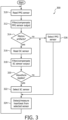
- a flowchart 300 illustrates an example process for detecting and/or measuring heartbeats.
- the process begins with obtaining an output from a PPG sensor, which may be PPG sensor 112, as shown with a block 310.
- the output of the PPG sensor may be filtered or have some type of compensation applied, such as processing for detecting motion artifacts, as illustrated in a block 312. If motion artifacts are detected in the output of the PPG sensor, the device for detecting heartbeats can change its operation.
- the determination of whether motion artifacts are detected in the output of the PPG sensor is illustrated with a decision block 314. If no motion artifacts are detected, the PPG sensor is selected for further heartbeat sensing, as illustrated by a block 326 being reached from the No branch from decision block 314.
- the output of an SC sensor is read, as illustrated with a block 316 being reached from a Yes branch of decision block 314.
- the SC sensor may be implemented as SC sensor 114.
- the output of the SC sensor may be filtered or have some type of compensation applied, such as processing to detect waveform ripples that may be indicative of heartbeats, as is illustrated in a block 318.
- the determination of whether the SC censor output includes waveform ripples is illustrated in a decision block 320. If no waveform ripples are detected in the SC sensor output, the PPG sensor is selected for detecting and/or measuring heartbeats, as illustrated with block 326 being reached from the No branch of decision block 320.
- the SC sensor is selected for further heartbeat sensing, as illustrated by a block 322 being reached via the Yes branch of decision block 320.
- the heartbeat sensing process detects and/or measures the heartbeat from the selected sensor, as illustrated in a block 324. The process continues by looping back to read the PPG sensor, as illustrated with the flowchart path from block 324 2 block 310.
- the process illustrated in flowchart 300 may tend to favor use of the PPG sensor, since that sensor is tested first for motion artifacts, as illustrated in decision block 314. According to other examples, the process illustrated in flowchart 300 can be rearranged to cause the SC sensor to be tested first, or concurrently with the PPG sensor. A switch between sensors can be undertaken when motion artifacts, or the lack thereof, are sensed in the output of the PPG sensor, or when waveform ripples, or lack thereof, are sensed in the output of the SC sensor. In addition, the selection of a sensor in the process illustrated in flowchart 300 may be implemented as turning the sensor(s) on, and/or turning the sensor(s) off, or changing from a low-power mode to a high-power mode, or vice versa.
- selection of the PPG sensor illustrated in block 326 may be implemented by turning off the SC sensor, by placing the SC sensor in a low-power mode or by ignoring the output of the SC sensor for the purpose of detecting and/or measuring heartbeats.
- Selection of the SC sensor illustrated in block 322 may be implemented by turning off the PPG sensor, by placing the PPG sensor in a low-power mode or by ignoring the output of the PPG sensor for the purpose of detecting and/or measuring heartbeats.
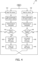
- a flowchart 400 illustrates an example process for detecting and/or measuring heartbeats.
- the process begins with obtaining an output from a PPG sensor, which may be PPG sensor 112, as shown with a block 410, and obtaining an output from an SC sensor, which may be SC sensor 114, as shown with a block 430.
- the output of the PPG sensor may be filtered or have some type of compensation applied, such as processing for detecting motion artifacts, as illustrated in a block 412. Detection and/or measurement of heartbeats using the PPG sensor is attempted, as illustrated with a block 414. If motion artifacts are detected in the output of the PPG sensor, the device for detecting heartbeats can change its operation.
- a decision block 416 The determination of whether motion artifacts are detected in the output of the PPG sensor is illustrated with a decision block 416. If no motion artifacts are detected, further heartbeat detection and/or measurement may be made using the PPG sensor, as illustrated by the No branch from decision block 416 being directed back to block 410 to obtain further PPG sensor readings.
- the output of the SC sensor may be filtered or have some type of compensation applied, such as processing to detect waveform ripples that may be indicative of heartbeats, as is illustrated in a block 432. Detection and/or measurement of heartbeats using the SC sensor is attempted, as illustrated with a block 434. A determination of whether the SC sensor output includes waveform ripples is illustrated in a decision block 434. If waveform ripples are detected, further heartbeat detection and/or measurement may be made using the SC sensor, as illustrated by the Yes branch from a decision block 436 being directed back to block 430 to obtain further SC sensor readings.
- the operation of the heartbeat sensing device can be changed.
- the PPG sensor is placed in a low-power mode, or powered off, as illustrated with a block 418 being reached from the Yes branch of decision block 416.
- the SC sensor is powered up, as illustrated in a block 420. Powering up the SC sensor may be implemented by changing from a low-power mode to a higher power mode, or by turning the sensor on, or by enabling an output of the SC sensor to be used to detect and/or measure heartbeats.
- the sensor output is read, as illustrated with the path from block 420 to block 430 in flowchart 400.
- the SC sensor if waveform ripples are not detected in the output of the sensor, the operation of the heartbeat sensing device can be changed.
- the SC sensor is placed in a low-power mode, or powered off, as illustrated with a block 438 being reached from the No branch of decision block 436.
- the PPG sensor is powered up, as illustrated in a block 440. Powering up the PPG sensor may be implemented by changing from a low-power mode to a higher power mode, or by turning the sensor on, or by enabling an output of the PPG sensor to be used to detect and/or measure heartbeats.
- the sensor output is read, as illustrated with the path from block 440 to block 410 in flowchart 400.
- the process illustrated in flowchart 400 can provide different modes of operation for the heartbeat sensing device, which modes of operation may be implemented in device 100 ( Fig. 1 ).
- modes of operation may be implemented in device 100 ( Fig. 1 ).
- one mode when there are no motion artifacts in the output of the PPG sensor and there are waveform ripples in the output of the SC sensor, each sensor can operate independently and concurrently to provide heartbeat data.
- a second mode motion artifacts are observed in the output of the PPG sensor, leading to the PPG sensor being turned off, or being placed in a low-power state, while waveform ripples are observed in the output of the SC sensor, which continues to operate in a normal state.
- a third mode motion artifacts are not observed in the output of the PPG sensor, which continues to operate in a normal state, while waveform ripples are absent from the output of the SC sensor, leading to the SC sensor being turned off, or being placed in a low-power state.
- motion artifacts are observed in the output of the PPG sensor and waveform ripples are absent from the output of the SC sensor, leading to the sensors being alternately switched between being powered up or powered down. This switching state continues either until motion artifacts are not observed in the output of the PPG sensor, or until waveform ripples are observed in the output of the SC sensor. Accordingly, the process illustrated in flowchart 400 uses the output of the sensor that is best able to provide heartbeat data, and switches between the sensors until a better heartbeat data source can be identified.
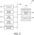
- FIG. 5 provides a schematic illustration of one embodiment of a computer system 500 that can perform the methods provided by various other embodiments, as described herein, and/or can function as the host computer system, a remote kiosk/terminal, a point-of-sale device, a mobile device, and/or a computer system. It should be noted that Fig. 5 is meant only to provide a generalized illustration of various components, any or all of which may be utilized as appropriate. Fig. 5 , therefore, broadly illustrates how individual system elements may be implemented in a relatively separated or relatively more integrated manner.
- the computer system 500 is shown comprising hardware elements that can be electrically coupled via a bus 505 (or may otherwise be in communication, as appropriate).
- the hardware elements may include one or more processors 510, including without limitation one or more general-purpose processors and/or one or more special-purpose processors (such as digital signal processing chips, graphics acceleration processors, and/or the like); one or more input devices 515, which can include without limitation a mouse, a keyboard and/or the like; and one or more output devices 520, which can include without limitation a display device, a printer and/or the like.
- the computer system 500 may further include (and/or be in communication with) one or more non-transitory storage devices 525, which can comprise, without limitation, local and/or network accessible storage, and/or can include, without limitation, a disk drive, a drive array, an optical storage device, solid-state storage device such as a random access memory (“RAM”) and/or a read-only memory (“ROM”), which can be programmable, flash-updateable and/or the like.
- RAM random access memory
- ROM read-only memory
- Such storage devices may be configured to implement any appropriate data stores, including without limitation, various file systems, database structures, and/or the like.
- the computer system 500 might also include a communications subsystem 530, which can include without limitation a modem, a network card (wireless or wired), an infrared communication device, a wireless communication device and/or chipset (such as a Bluetooth TM device, an 802.11 device, a WiFi device, a WiMax device, cellular communication facilities, etc.), and/or the like.
- the communications subsystem 530 may permit data to be exchanged with a network (such as the network described below, to name one example), other computer systems, and/or any other devices described herein.
- the computer system 500 will further comprise a working memory 535, which can include a RAM or ROM device, as described above.
- the computer system 500 also can comprise software elements, shown as being currently located within the working memory 535, including an operating system 540, device drivers, executable libraries, and/or other code, such as one or more application programs 545, which may comprise computer programs provided by various embodiments, and/or may be designed to implement methods, and/or configure systems, provided by other embodiments, as described herein.
- application programs 545 may comprise computer programs provided by various embodiments, and/or may be designed to implement methods, and/or configure systems, provided by other embodiments, as described herein.
- code and/or instructions can be used to configure and/or adapt a general purpose computer (or other device) to perform one or more operations in accordance with the described methods.
- a set of these instructions and/or code might be stored on a computer-readable storage medium, such as the storage device(s) 525 described above.
- the storage medium might be incorporated within a computer system, such as the system 500.
- the storage medium might be separate from a computer system (e.g., a removable medium, such as a compact disc), and/or provided in an installation package, such that the storage medium can be used to program, configure and/or adapt a general purpose computer with the instructions/code stored thereon.
- These instructions might take the form of executable code, which is executable by the computer system 500 and/or might take the form of source and/or installable code, which, upon compilation and/or installation on the computer system 500 (e.g., using any of a variety of generally available compilers, installation programs, compression/decompression utilities, etc.) then takes the form of executable code.
- a computer system (such as the computer system 500) may be employed to perform methods in accordance with various embodiments. According to a set of embodiments, some or all of the procedures of such methods are performed by the computer system 500 in response to processor 510 executing one or more sequences of one or more instructions (which might be incorporated into the operating system 540 and/or other code, such as an application program 545) contained in the working memory 535. Such instructions may be read into the working memory 535 from another computer-readable medium, such as one or more of the storage device(s) 525. Merely by way of example, execution of the sequences of instructions contained in the working memory 535 might cause the processor(s) 510 to perform one or more procedures of the methods described herein.
- machine-readable medium and “computer-readable medium,” as used herein, refer to any medium that participates in providing data that causes a machine to operate in a specific fashion.
- a machine-readable medium contains machine-executable instructions for performing a function, such as a method, for detecting heart rate and/or heart rate variability.
- various computer-readable media might be involved in providing instructions/code to processor(s) 510 for execution and/or might be used to store and/or carry such instructions/code (e.g., as signals).
- a computer-readable medium is a physical and/or tangible storage medium.
- Non-volatile media include, for example, optical and/or magnetic disks, such as the storage device(s) 525.
- Volatile media include, without limitation, dynamic memory, such as the working memory 535.
- Transmission media include, without limitation, coaxial cables, copper wire and fiber optics, including the wires that comprise the bus 505, as well as the various components of the communication subsystem 530 (and/or the media by which the communications subsystem 530 provides communication with other devices).
- transmission media can also take the form of waves (including without limitation radio, acoustic and/or light waves, such as those generated during radio-wave and infrared data communications).
- Various forms of computer-readable media may be involved in carrying one or more sequences of one or more instructions to the processor(s) 510 for execution.
- the instructions may initially be carried on a magnetic disk and/or optical disc of a remote computer.
- a remote computer might load the instructions into its dynamic memory and send the instructions as signals over a transmission medium to be received and/or executed by the computer system 500.
- These signals which might be in the form of electromagnetic signals, acoustic signals, optical signals and/or the like, are all examples of carrier waves on which instructions can be encoded and that may be employed in some embodiments in accordance with the present disclosure.
- the communications subsystem 530 (and/or components thereof) generally will receive the signals, and the bus 505 then might carry the signals (and/or the data, instructions, etc. carried by the signals) to the working memory 535, from which the processor(s) 505 retrieves and executes the instructions.
- the instructions received by the working memory 535 may optionally be stored on a storage device 525 either before or after execution by the processor(s) 510.
- configurations may be described as a process that is depicted as a flow diagram or block diagram. Although each may describe the operations as a sequential process, many of the operations can be performed in parallel or concurrently. In addition, the order of the operations may be rearranged. A process may have additional stages or functions not included in the figure.
- a statement that a value exceeds (or is more than) a first threshold value is equivalent to a statement that the value meets or exceeds a second threshold value that is slightly greater than the first threshold value, e.g., the second threshold value being one value higher than the first threshold value in the resolution of a relevant system.
- a statement that a value is less than (or is within) a first threshold value is equivalent to a statement that the value is less than or equal to a second threshold value that is slightly lower than the first threshold value, e.g., the second threshold value being one value lower than the first threshold value in the resolution of the relevant system.
- examples of the methods may be implemented by hardware, software, firmware, middleware, microcode, hardware description languages, or any combination thereof.
- the program code or code segments to perform the necessary tasks may be stored in a non-transitory computer-readable medium such as a storage medium. Processors may perform the described tasks.
- Embodiments of the present disclosure are described above with reference to block diagrams and/or operational illustrations of methods, systems, and computer program products according to embodiments of the present disclosure.
- the functions/acts noted in the blocks may occur out of the order as shown in any flowchart.
- two blocks shown in succession may in fact be executed substantially concurrent or the blocks may sometimes be executed in the reverse order, depending upon the functionality/acts involved.
- not all of the blocks shown in any flowchart need to be performed and/or executed. For example, if a given flowchart has five blocks containing functions/acts, it may be the case that only three of the five blocks are performed and/or executed. In this example, any of the three of the five blocks may be performed and/or executed.
Landscapes
- Health & Medical Sciences (AREA)
- Life Sciences & Earth Sciences (AREA)
- Engineering & Computer Science (AREA)
- Cardiology (AREA)
- Molecular Biology (AREA)
- General Health & Medical Sciences (AREA)
- Biophysics (AREA)
- Pathology (AREA)
- Veterinary Medicine (AREA)
- Biomedical Technology (AREA)
- Heart & Thoracic Surgery (AREA)
- Medical Informatics (AREA)
- Public Health (AREA)
- Surgery (AREA)
- Animal Behavior & Ethology (AREA)
- Physics & Mathematics (AREA)
- Physiology (AREA)
- Signal Processing (AREA)
- Nuclear Medicine, Radiotherapy & Molecular Imaging (AREA)
- Radiology & Medical Imaging (AREA)
- Artificial Intelligence (AREA)
- Computer Vision & Pattern Recognition (AREA)
- Psychiatry (AREA)
- Dermatology (AREA)
- Measuring Pulse, Heart Rate, Blood Pressure Or Blood Flow (AREA)
Claims (9)
- Appareil (100) pour déterminer une fréquence cardiaque et/ou une variabilité de fréquence cardiaque par détection de battements cardiaques d'un sujet, l'appareil comprenant:un capteur photopléthysmographe (112) configuré pour détecter les battements cardiaques du sujet et fournir un premier signal de mesure influencé par les battements cardiaques;un capteur de conductance cutanée (114) configuré pour détecter les battements cardiaques du sujet et fournir un second signal de mesure influencé par les battements cardiaques; etune unité de traitement (110) configurée pour recevoir le premier signal de mesure et le second signal de mesure,dans lequel l'unité de traitement (110) est configurée pour analyser et déterminer une fiabilité d'un ou plusieurs parmi le premier signal de mesure ou le second signal de mesure pour identifier les battements cardiaques;dans lequel l'analyse du second signal de mesure comprend l'analyse d'une ondulation de forme d'onde; etpour sélectionner ou désélectionner un ou plusieurs parmi le premier signal ou le second signal pour déterminer la fréquence cardiaque ou la variabilité de fréquence cardiaque du sujet sur la base de la fiabilité déterminée.
- Appareil selon la revendication 1, dans lequel l'unité de traitement (110) est configurée pour sélectionner un ou plusieurs parmi le premier signal de mesure ou le second signal de mesure sur la base d'un ou plusieurs parmi le premier signal de mesure ou le second signal de mesure présentant des indices de battements cardiaques.
- Appareil selon la revendication 1, dans lequel l'unité de traitement (110) est configurée pour sélectionner un ou plusieurs parmi le premier signal de mesure ou le second signal de mesure sur la base du premier signal de mesure présentant des indices d'artéfacts de mouvement.
- Appareil selon la revendication 1, dans lequel l'unité de traitement (110) est en outre configurée pour appliquer un filtre numérique à un ou plusieurs parmi le premier signal de mesure ou le second signal de mesure.
- Appareil selon la revendication 1, dans lequel le capteur de conductance cutanée (114) est sensible à des fréquences supérieures à 100 Hz.
- Appareil selon la revendication 1, dans lequel l'unité de traitement (110) est en outre configurée pour activer ou désactiver sélectivement un ou plusieurs parmi le capteur photopléthysmographe (112) ou le capteur de conductance cutanée (114) pour gérer la consommation d'énergie.
- Appareil selon la revendication 1, comprenant en outre un accéléromètre (122), et dans lequel l'unité de traitement (110) est configurée pour activer ou désactiver un ou plusieurs parmi le capteur photopléthysmographe (112) ou le capteur de conductance cutanée (114) en réponse à une sortie de l'accéléromètre (122).
- Appareil selon la revendication 1, dans lequel l'unité de traitement (110) est en outre configurée pour calculer une pression sanguine diastolique à partir d'un ou plusieurs parmi le premier signal de mesure ou le second signal de mesure.
- Procédé pour déterminer une fréquence cardiaque et/ou une variabilité de fréquence cardiaque par détection de battements cardiaques d'un sujet, le procédé consistant à:fournir un capteur photopléthysmographe (112) configuré pour détecter les battements cardiaques du sujet et obtenir un premier signal de mesure influencé par les battements cardiaques;fournir un capteur de conductance cutanée (114) configuré pour détecter les battements cardiaques du sujet et obtenir un second signal de mesure influencé par les battements cardiaques; etfournir une unité de traitement (110) configurée pour recevoir le premier signal de mesure et le second signal de mesure,dans lequel l'unité de traitement (110) est configurée pour analyser et déterminer une fiabilité d'un ou plusieurs parmi le premier signal de mesure ou le second signal de mesure pour identifier les battements cardiaques;dans lequel l'analyse du second signal de mesure comprend l'analyse d'une ondulation de forme d'onde; etpour sélectionner ou désélectionner un ou plusieurs parmi le premier signal ou le second signal pour déterminer la fréquence cardiaque ou la variabilité de fréquence cardiaque du sujet sur la base de la fiabilité déterminée.
Applications Claiming Priority (3)
| Application Number | Priority Date | Filing Date | Title |
|---|---|---|---|
| US201562119977P | 2015-02-24 | 2015-02-24 | |
| US201562265437P | 2015-12-10 | 2015-12-10 | |
| PCT/IB2016/050805 WO2016135583A1 (fr) | 2015-02-24 | 2016-02-16 | Dispositif de détection de fréquence cardiaque et de variabilité de fréquence cardiaque |
Publications (2)
| Publication Number | Publication Date |
|---|---|
| EP3261520A1 EP3261520A1 (fr) | 2018-01-03 |
| EP3261520B1 true EP3261520B1 (fr) | 2023-04-12 |
Family
ID=55451517
Family Applications (1)
| Application Number | Title | Priority Date | Filing Date |
|---|---|---|---|
| EP16707210.7A Active EP3261520B1 (fr) | 2015-02-24 | 2016-02-16 | Dispositif de détection de fréquence cardiaque et de variabilité de fréquence cardiaque |
Country Status (7)
| Country | Link |
|---|---|
| US (1) | US10405761B2 (fr) |
| EP (1) | EP3261520B1 (fr) |
| JP (1) | JP6679602B2 (fr) |
| CN (1) | CN107257654B (fr) |
| AU (1) | AU2016225134A1 (fr) |
| RU (1) | RU2017133140A (fr) |
| WO (1) | WO2016135583A1 (fr) |
Families Citing this family (9)
| Publication number | Priority date | Publication date | Assignee | Title |
|---|---|---|---|---|
| WO2017079580A1 (fr) * | 2015-11-06 | 2017-05-11 | Lifeq Global Limited | Système et procédé écoénergétique pour surveillance physiologique |
| JP2017104382A (ja) * | 2015-12-11 | 2017-06-15 | セイコーエプソン株式会社 | 生体情報検出装置及び生体情報検出装置の制御方法 |
| EP3342332B1 (fr) * | 2016-12-28 | 2024-03-13 | Samsung Electronics Co., Ltd. | Appareil et procédé de combinaison de caractéristiques de bio-signal adaptatif |
| EP3430993A1 (fr) * | 2017-07-21 | 2019-01-23 | Koninklijke Philips N.V. | Appareil permettant de mesurer un paramètre physiologique au moyen d'un capteur vestimentaire |
| KR102170187B1 (ko) * | 2018-02-05 | 2020-10-26 | 서울대학교산학협력단 | 맥파 전달 시간 측정 장치 및 방법 |
| US11331003B2 (en) * | 2018-03-27 | 2022-05-17 | Samsung Electronics Co., Ltd. | Context-aware respiration rate determination using an electronic device |
| US20210219923A1 (en) * | 2018-05-08 | 2021-07-22 | University Of Pittsburgh-Of The Commonwealth System Of Higher Education | System for monitoring and providing alerts of a fall risk by predicting risk of experiencing symptoms related to abnormal blood pressure(s) and/or heart rate |
| WO2023209345A1 (fr) * | 2022-04-27 | 2023-11-02 | Prevayl Innovations Limited | Module électronique et procédé |
| CN116269242B (zh) * | 2023-05-17 | 2023-07-18 | 广州培生智能科技有限公司 | 一种基于互联网的老年人健康状况实时监控系统 |
Family Cites Families (17)
| Publication number | Priority date | Publication date | Assignee | Title |
|---|---|---|---|---|
| KR100455286B1 (ko) | 2002-01-11 | 2004-11-06 | 삼성전자주식회사 | 생리신호획득 및 해석을 이용한 동물의 상태 파악 방법 및장치 |
| KR101084554B1 (ko) | 2003-09-12 | 2011-11-17 | 보디미디어 인코퍼레이티드 | 심장 관련 파라미터를 측정하기 위한 방법 및 장치 |
| US20060178588A1 (en) * | 2005-01-03 | 2006-08-10 | Lee Brody | System and method for isolating effects of basal autonomic nervous system activity on heart rate variability |
| EP1906812A1 (fr) | 2005-07-28 | 2008-04-09 | Boris Schwartz | Biocapteur fixe a l'oreille |
| JP2009528141A (ja) * | 2006-02-28 | 2009-08-06 | コーニンクレッカ フィリップス エレクトロニクス エヌ ヴィ | ネックカラー部に配される電子機器を有するバイオメトリックモニタ |
| US20120123232A1 (en) * | 2008-12-16 | 2012-05-17 | Kayvan Najarian | Method and apparatus for determining heart rate variability using wavelet transformation |
| US8140143B2 (en) * | 2009-04-16 | 2012-03-20 | Massachusetts Institute Of Technology | Washable wearable biosensor |
| KR101025510B1 (ko) | 2009-06-10 | 2011-04-04 | 연세대학교 산학협력단 | 감성인식장치의 개인별 최적화시스템 및 그 최적화 방법 |
| BR112013026063B1 (pt) * | 2011-04-14 | 2021-08-31 | Koninklijke Philips N.V | Dispositivo de medição de estresse para a determinação de um nível de estresse de um usuário, dispositivo trajável usado por um usuário, sistema de medição de estresse, método de medição de estresse para a determinação de um nível de estresse de um usuário, dispositivo de medição de pressão sanguínea e método de medição de pressão sanguínea |
| RU2629795C2 (ru) * | 2011-04-29 | 2017-09-04 | Конинклейке Филипс Н.В. | Устройство для использования в детекторе падения или системе обнаружения падений и способ управления таким устройством |
| JP6149037B2 (ja) * | 2011-09-16 | 2017-06-14 | コーニンクレッカ フィリップス エヌ ヴェKoninklijke Philips N.V. | ポータブル装置、心拍を決定する方法、システム及びコンピュータプログラム |
| CN104254275A (zh) * | 2012-02-22 | 2014-12-31 | 阿克拉里斯医疗有限责任公司 | 生理信号检测装置和系统 |
| US9641239B2 (en) | 2012-06-22 | 2017-05-02 | Fitbit, Inc. | Adaptive data transfer using bluetooth |
| CN203252647U (zh) * | 2012-09-29 | 2013-10-30 | 艾利佛公司 | 用于判定生理特征的可佩带的设备 |
| WO2014147024A1 (fr) | 2013-03-16 | 2014-09-25 | Empatica, Inc. | Appareil pour mesure d'activité électrocutanée à compensation de courant |
| US9014790B2 (en) | 2013-06-03 | 2015-04-21 | Fitbit, Inc. | Heart rate data collection |
| CN106714679A (zh) | 2014-09-30 | 2017-05-24 | 皇家飞利浦有限公司 | 用于皮肤电导测量的可穿戴装置 |
-
2016
- 2016-02-16 US US15/549,244 patent/US10405761B2/en active Active
- 2016-02-16 WO PCT/IB2016/050805 patent/WO2016135583A1/fr active Application Filing
- 2016-02-16 CN CN201680011847.7A patent/CN107257654B/zh active Active
- 2016-02-16 JP JP2017541940A patent/JP6679602B2/ja active Active
- 2016-02-16 RU RU2017133140A patent/RU2017133140A/ru not_active Application Discontinuation
- 2016-02-16 EP EP16707210.7A patent/EP3261520B1/fr active Active
- 2016-02-16 AU AU2016225134A patent/AU2016225134A1/en not_active Abandoned
Also Published As
| Publication number | Publication date |
|---|---|
| JP2018505737A (ja) | 2018-03-01 |
| US10405761B2 (en) | 2019-09-10 |
| EP3261520A1 (fr) | 2018-01-03 |
| CN107257654A (zh) | 2017-10-17 |
| WO2016135583A1 (fr) | 2016-09-01 |
| AU2016225134A1 (en) | 2017-10-12 |
| RU2017133140A (ru) | 2019-03-25 |
| US20180028080A1 (en) | 2018-02-01 |
| JP6679602B2 (ja) | 2020-04-15 |
| CN107257654B (zh) | 2020-08-25 |
Similar Documents
| Publication | Publication Date | Title |
|---|---|---|
| EP3261520B1 (fr) | Dispositif de détection de fréquence cardiaque et de variabilité de fréquence cardiaque | |
| US10595786B2 (en) | Confidence indicator for physiological measurements using a wearable sensor platform | |
| KR102486700B1 (ko) | 혈압 추정 방법 및 장치 | |
| EP3646781A1 (fr) | Dispositif de traitement d'informations, procédé de traitement d'informations, et programme | |
| JP6277716B2 (ja) | 生体情報計測機器、生体情報処理方法及びプログラム | |
| US9504401B2 (en) | Atrial fibrillation analyzer and program | |
| US20080294058A1 (en) | Wearable Device, System and Method for Measuring a Pulse While a User is in Motion | |
| US10750988B2 (en) | Fatigue degree determination device, and fatigue degree determination method | |
| KR20190016891A (ko) | 모션 센서를 이용한 연속 심박수 및 심장박동 이벤트 감지를 위한 시스템 및 방법 | |
| WO2018105447A1 (fr) | Dispositif d'estimation d'état de contact, et dispositif de mesure de signal biologique | |
| US9504400B2 (en) | Atrial fibrillation analyzer, atrial fibrillation analysis system, atrial fibrillation analysis method, and program | |
| JP2016123473A (ja) | 脈波測定装置、および脈波測定装置の駆動制御方法 | |
| JP2016185288A (ja) | 携帯型心電計およびコンピュータプログラム | |
| US11191483B2 (en) | Wearable blood pressure measurement systems | |
| JP2007289540A (ja) | ストレスセンサシステム | |
| US20140194761A1 (en) | Method and apparatus for monitoring biosignal with low power consumption | |
| US20160361023A1 (en) | Techniques for determining physiological properties of a user using vascular-related signals qualified by activity state | |
| CN113365550A (zh) | 用于基于rem睡眠阶段计算恢复指数的方法及其电子设备 | |
| KR101586729B1 (ko) | 생체신호 모니터링 장치 및 시스템, 및 이를 이용한 생체신호 모니터링 방법 | |
| US9730644B1 (en) | Circuits and methods for selecting a mode of operation of a photoplethysmographic sensor | |
| US10390758B2 (en) | Method and apparatus for triage and subsequent escalation based on biosignals or biometrics | |
| JP2007209679A (ja) | 計測装置、計測装置の制御方法および制御プログラム | |
| KR20160062576A (ko) | 생체신호 모니터링 장치 및 시스템, 및 이를 이용한 생체신호 모니터링 방법 | |
| CA3232038A1 (fr) | Dispositif et systeme pour detecter des anomalies du rythme cardiaque | |
| KR101311279B1 (ko) | Ecg 신호 검출 시스템 및 방법 |
Legal Events
| Date | Code | Title | Description |
|---|---|---|---|
| STAA | Information on the status of an ep patent application or granted ep patent |
Free format text: STATUS: THE INTERNATIONAL PUBLICATION HAS BEEN MADE |
|
| PUAI | Public reference made under article 153(3) epc to a published international application that has entered the european phase |
Free format text: ORIGINAL CODE: 0009012 |
|
| STAA | Information on the status of an ep patent application or granted ep patent |
Free format text: STATUS: REQUEST FOR EXAMINATION WAS MADE |
|
| 17P | Request for examination filed |
Effective date: 20170925 |
|
| AK | Designated contracting states |
Kind code of ref document: A1 Designated state(s): AL AT BE BG CH CY CZ DE DK EE ES FI FR GB GR HR HU IE IS IT LI LT LU LV MC MK MT NL NO PL PT RO RS SE SI SK SM TR |
|
| AX | Request for extension of the european patent |
Extension state: BA ME |
|
| DAV | Request for validation of the european patent (deleted) | ||
| DAX | Request for extension of the european patent (deleted) | ||
| RAP1 | Party data changed (applicant data changed or rights of an application transferred) |
Owner name: KONINKLIJKE PHILIPS N.V. |
|
| STAA | Information on the status of an ep patent application or granted ep patent |
Free format text: STATUS: EXAMINATION IS IN PROGRESS |
|
| 17Q | First examination report despatched |
Effective date: 20200729 |
|
| STAA | Information on the status of an ep patent application or granted ep patent |
Free format text: STATUS: EXAMINATION IS IN PROGRESS |
|
| STAA | Information on the status of an ep patent application or granted ep patent |
Free format text: STATUS: EXAMINATION IS IN PROGRESS |
|
| GRAP | Despatch of communication of intention to grant a patent |
Free format text: ORIGINAL CODE: EPIDOSNIGR1 |
|
| STAA | Information on the status of an ep patent application or granted ep patent |
Free format text: STATUS: GRANT OF PATENT IS INTENDED |
|
| RIC1 | Information provided on ipc code assigned before grant |
Ipc: A61B 5/0531 20210101ALI20221028BHEP Ipc: A61B 5/0245 20060101ALI20221028BHEP Ipc: A61B 5/024 20060101ALI20221028BHEP Ipc: A61B 5/00 20060101AFI20221028BHEP |
|
| INTG | Intention to grant announced |
Effective date: 20221205 |
|
| GRAS | Grant fee paid |
Free format text: ORIGINAL CODE: EPIDOSNIGR3 |
|
| GRAA | (expected) grant |
Free format text: ORIGINAL CODE: 0009210 |
|
| STAA | Information on the status of an ep patent application or granted ep patent |
Free format text: STATUS: THE PATENT HAS BEEN GRANTED |
|
| AK | Designated contracting states |
Kind code of ref document: B1 Designated state(s): AL AT BE BG CH CY CZ DE DK EE ES FI FR GB GR HR HU IE IS IT LI LT LU LV MC MK MT NL NO PL PT RO RS SE SI SK SM TR |
|
| REG | Reference to a national code |
Ref country code: GB Ref legal event code: FG4D |
|
| REG | Reference to a national code |
Ref country code: CH Ref legal event code: EP |
|
| REG | Reference to a national code |
Ref country code: DE Ref legal event code: R096 Ref document number: 602016078777 Country of ref document: DE |
|
| REG | Reference to a national code |
Ref country code: IE Ref legal event code: FG4D |
|
| REG | Reference to a national code |
Ref country code: AT Ref legal event code: REF Ref document number: 1559353 Country of ref document: AT Kind code of ref document: T Effective date: 20230515 |
|
| REG | Reference to a national code |
Ref country code: LT Ref legal event code: MG9D |
|
| REG | Reference to a national code |
Ref country code: NL Ref legal event code: MP Effective date: 20230412 |
|
| REG | Reference to a national code |
Ref country code: AT Ref legal event code: MK05 Ref document number: 1559353 Country of ref document: AT Kind code of ref document: T Effective date: 20230412 |
|
| PG25 | Lapsed in a contracting state [announced via postgrant information from national office to epo] |
Ref country code: NL Free format text: LAPSE BECAUSE OF FAILURE TO SUBMIT A TRANSLATION OF THE DESCRIPTION OR TO PAY THE FEE WITHIN THE PRESCRIBED TIME-LIMIT Effective date: 20230412 |
|
| PG25 | Lapsed in a contracting state [announced via postgrant information from national office to epo] |
Ref country code: SE Free format text: LAPSE BECAUSE OF FAILURE TO SUBMIT A TRANSLATION OF THE DESCRIPTION OR TO PAY THE FEE WITHIN THE PRESCRIBED TIME-LIMIT Effective date: 20230412 Ref country code: PT Free format text: LAPSE BECAUSE OF FAILURE TO SUBMIT A TRANSLATION OF THE DESCRIPTION OR TO PAY THE FEE WITHIN THE PRESCRIBED TIME-LIMIT Effective date: 20230814 Ref country code: NO Free format text: LAPSE BECAUSE OF FAILURE TO SUBMIT A TRANSLATION OF THE DESCRIPTION OR TO PAY THE FEE WITHIN THE PRESCRIBED TIME-LIMIT Effective date: 20230712 Ref country code: ES Free format text: LAPSE BECAUSE OF FAILURE TO SUBMIT A TRANSLATION OF THE DESCRIPTION OR TO PAY THE FEE WITHIN THE PRESCRIBED TIME-LIMIT Effective date: 20230412 Ref country code: AT Free format text: LAPSE BECAUSE OF FAILURE TO SUBMIT A TRANSLATION OF THE DESCRIPTION OR TO PAY THE FEE WITHIN THE PRESCRIBED TIME-LIMIT Effective date: 20230412 |
|
| PG25 | Lapsed in a contracting state [announced via postgrant information from national office to epo] |
Ref country code: RS Free format text: LAPSE BECAUSE OF FAILURE TO SUBMIT A TRANSLATION OF THE DESCRIPTION OR TO PAY THE FEE WITHIN THE PRESCRIBED TIME-LIMIT Effective date: 20230412 Ref country code: PL Free format text: LAPSE BECAUSE OF FAILURE TO SUBMIT A TRANSLATION OF THE DESCRIPTION OR TO PAY THE FEE WITHIN THE PRESCRIBED TIME-LIMIT Effective date: 20230412 Ref country code: LV Free format text: LAPSE BECAUSE OF FAILURE TO SUBMIT A TRANSLATION OF THE DESCRIPTION OR TO PAY THE FEE WITHIN THE PRESCRIBED TIME-LIMIT Effective date: 20230412 Ref country code: LT Free format text: LAPSE BECAUSE OF FAILURE TO SUBMIT A TRANSLATION OF THE DESCRIPTION OR TO PAY THE FEE WITHIN THE PRESCRIBED TIME-LIMIT Effective date: 20230412 Ref country code: IS Free format text: LAPSE BECAUSE OF FAILURE TO SUBMIT A TRANSLATION OF THE DESCRIPTION OR TO PAY THE FEE WITHIN THE PRESCRIBED TIME-LIMIT Effective date: 20230812 Ref country code: HR Free format text: LAPSE BECAUSE OF FAILURE TO SUBMIT A TRANSLATION OF THE DESCRIPTION OR TO PAY THE FEE WITHIN THE PRESCRIBED TIME-LIMIT Effective date: 20230412 Ref country code: GR Free format text: LAPSE BECAUSE OF FAILURE TO SUBMIT A TRANSLATION OF THE DESCRIPTION OR TO PAY THE FEE WITHIN THE PRESCRIBED TIME-LIMIT Effective date: 20230713 Ref country code: AL Free format text: LAPSE BECAUSE OF FAILURE TO SUBMIT A TRANSLATION OF THE DESCRIPTION OR TO PAY THE FEE WITHIN THE PRESCRIBED TIME-LIMIT Effective date: 20230412 |
|
| PG25 | Lapsed in a contracting state [announced via postgrant information from national office to epo] |
Ref country code: FI Free format text: LAPSE BECAUSE OF FAILURE TO SUBMIT A TRANSLATION OF THE DESCRIPTION OR TO PAY THE FEE WITHIN THE PRESCRIBED TIME-LIMIT Effective date: 20230412 |
|
| REG | Reference to a national code |
Ref country code: DE Ref legal event code: R097 Ref document number: 602016078777 Country of ref document: DE |
|
| PG25 | Lapsed in a contracting state [announced via postgrant information from national office to epo] |
Ref country code: SK Free format text: LAPSE BECAUSE OF FAILURE TO SUBMIT A TRANSLATION OF THE DESCRIPTION OR TO PAY THE FEE WITHIN THE PRESCRIBED TIME-LIMIT Effective date: 20230412 |
|
| PG25 | Lapsed in a contracting state [announced via postgrant information from national office to epo] |
Ref country code: SM Free format text: LAPSE BECAUSE OF FAILURE TO SUBMIT A TRANSLATION OF THE DESCRIPTION OR TO PAY THE FEE WITHIN THE PRESCRIBED TIME-LIMIT Effective date: 20230412 Ref country code: SK Free format text: LAPSE BECAUSE OF FAILURE TO SUBMIT A TRANSLATION OF THE DESCRIPTION OR TO PAY THE FEE WITHIN THE PRESCRIBED TIME-LIMIT Effective date: 20230412 Ref country code: RO Free format text: LAPSE BECAUSE OF FAILURE TO SUBMIT A TRANSLATION OF THE DESCRIPTION OR TO PAY THE FEE WITHIN THE PRESCRIBED TIME-LIMIT Effective date: 20230412 Ref country code: EE Free format text: LAPSE BECAUSE OF FAILURE TO SUBMIT A TRANSLATION OF THE DESCRIPTION OR TO PAY THE FEE WITHIN THE PRESCRIBED TIME-LIMIT Effective date: 20230412 Ref country code: DK Free format text: LAPSE BECAUSE OF FAILURE TO SUBMIT A TRANSLATION OF THE DESCRIPTION OR TO PAY THE FEE WITHIN THE PRESCRIBED TIME-LIMIT Effective date: 20230412 Ref country code: CZ Free format text: LAPSE BECAUSE OF FAILURE TO SUBMIT A TRANSLATION OF THE DESCRIPTION OR TO PAY THE FEE WITHIN THE PRESCRIBED TIME-LIMIT Effective date: 20230412 |
|
| PLBE | No opposition filed within time limit |
Free format text: ORIGINAL CODE: 0009261 |
|
| STAA | Information on the status of an ep patent application or granted ep patent |
Free format text: STATUS: NO OPPOSITION FILED WITHIN TIME LIMIT |
|
| 26N | No opposition filed |
Effective date: 20240115 |
|
| PGFP | Annual fee paid to national office [announced via postgrant information from national office to epo] |
Ref country code: DE Payment date: 20240228 Year of fee payment: 9 Ref country code: GB Payment date: 20240220 Year of fee payment: 9 |
|
| PG25 | Lapsed in a contracting state [announced via postgrant information from national office to epo] |
Ref country code: SI Free format text: LAPSE BECAUSE OF FAILURE TO SUBMIT A TRANSLATION OF THE DESCRIPTION OR TO PAY THE FEE WITHIN THE PRESCRIBED TIME-LIMIT Effective date: 20230412 |
|
| PG25 | Lapsed in a contracting state [announced via postgrant information from national office to epo] |
Ref country code: SI Free format text: LAPSE BECAUSE OF FAILURE TO SUBMIT A TRANSLATION OF THE DESCRIPTION OR TO PAY THE FEE WITHIN THE PRESCRIBED TIME-LIMIT Effective date: 20230412 Ref country code: IT Free format text: LAPSE BECAUSE OF FAILURE TO SUBMIT A TRANSLATION OF THE DESCRIPTION OR TO PAY THE FEE WITHIN THE PRESCRIBED TIME-LIMIT Effective date: 20230412 |
|
| PGFP | Annual fee paid to national office [announced via postgrant information from national office to epo] |
Ref country code: FR Payment date: 20240226 Year of fee payment: 9 |
|
| PG25 | Lapsed in a contracting state [announced via postgrant information from national office to epo] |
Ref country code: MC Free format text: LAPSE BECAUSE OF FAILURE TO SUBMIT A TRANSLATION OF THE DESCRIPTION OR TO PAY THE FEE WITHIN THE PRESCRIBED TIME-LIMIT Effective date: 20230412 |
|
| REG | Reference to a national code |
Ref country code: CH Ref legal event code: PL |
|
| PG25 | Lapsed in a contracting state [announced via postgrant information from national office to epo] |
Ref country code: LU Free format text: LAPSE BECAUSE OF NON-PAYMENT OF DUE FEES Effective date: 20240216 |