EP3259404B1 - Gravity-base-type structure for supporting and anchoring an offshore wind turbine, and method for towing and installing same in the sea - Google Patents
Gravity-base-type structure for supporting and anchoring an offshore wind turbine, and method for towing and installing same in the sea Download PDFInfo
- Publication number
- EP3259404B1 EP3259404B1 EP16714960.8A EP16714960A EP3259404B1 EP 3259404 B1 EP3259404 B1 EP 3259404B1 EP 16714960 A EP16714960 A EP 16714960A EP 3259404 B1 EP3259404 B1 EP 3259404B1
- Authority
- EP
- European Patent Office
- Prior art keywords
- caisson
- caissons
- block
- base
- sea
- Prior art date
- Legal status (The legal status is an assumption and is not a legal conclusion. Google has not performed a legal analysis and makes no representation as to the accuracy of the status listed.)
- Active
Links
- 238000000034 method Methods 0.000 title claims description 21
- 238000004873 anchoring Methods 0.000 title claims description 18
- 230000005484 gravity Effects 0.000 claims description 27
- 238000007654 immersion Methods 0.000 claims description 20
- XLYOFNOQVPJJNP-UHFFFAOYSA-N water Substances O XLYOFNOQVPJJNP-UHFFFAOYSA-N 0.000 claims description 18
- 230000002093 peripheral effect Effects 0.000 claims description 15
- 230000000284 resting effect Effects 0.000 claims description 13
- 239000007787 solid Substances 0.000 claims description 10
- 238000005192 partition Methods 0.000 claims description 8
- 239000013535 sea water Substances 0.000 claims description 7
- 230000007717 exclusion Effects 0.000 claims description 6
- 230000002706 hydrostatic effect Effects 0.000 claims description 4
- 238000005086 pumping Methods 0.000 claims description 4
- 238000000151 deposition Methods 0.000 claims 1
- 238000009434 installation Methods 0.000 description 13
- 238000007667 floating Methods 0.000 description 9
- 238000005188 flotation Methods 0.000 description 6
- 230000000694 effects Effects 0.000 description 5
- 238000010276 construction Methods 0.000 description 4
- 238000011084 recovery Methods 0.000 description 4
- 239000000463 material Substances 0.000 description 3
- 125000006850 spacer group Chemical group 0.000 description 3
- XEEYBQQBJWHFJM-UHFFFAOYSA-N Iron Chemical compound [Fe] XEEYBQQBJWHFJM-UHFFFAOYSA-N 0.000 description 2
- 229910000831 Steel Inorganic materials 0.000 description 2
- 230000000368 destabilizing effect Effects 0.000 description 2
- 238000004519 manufacturing process Methods 0.000 description 2
- 239000010959 steel Substances 0.000 description 2
- 230000000903 blocking effect Effects 0.000 description 1
- 238000006073 displacement reaction Methods 0.000 description 1
- 230000002687 intercalation Effects 0.000 description 1
- 238000009830 intercalation Methods 0.000 description 1
- 229910052742 iron Inorganic materials 0.000 description 1
- 239000007788 liquid Substances 0.000 description 1
- 230000000750 progressive effect Effects 0.000 description 1
- 230000002787 reinforcement Effects 0.000 description 1
Images


Classifications
-
- E—FIXED CONSTRUCTIONS
- E02—HYDRAULIC ENGINEERING; FOUNDATIONS; SOIL SHIFTING
- E02B—HYDRAULIC ENGINEERING
- E02B17/00—Artificial islands mounted on piles or like supports, e.g. platforms on raisable legs or offshore constructions; Construction methods therefor
- E02B17/02—Artificial islands mounted on piles or like supports, e.g. platforms on raisable legs or offshore constructions; Construction methods therefor placed by lowering the supporting construction to the bottom, e.g. with subsequent fixing thereto
- E02B17/025—Reinforced concrete structures
-
- B—PERFORMING OPERATIONS; TRANSPORTING
- B63—SHIPS OR OTHER WATERBORNE VESSELS; RELATED EQUIPMENT
- B63B—SHIPS OR OTHER WATERBORNE VESSELS; EQUIPMENT FOR SHIPPING
- B63B35/00—Vessels or similar floating structures specially adapted for specific purposes and not otherwise provided for
- B63B35/003—Vessels or similar floating structures specially adapted for specific purposes and not otherwise provided for for transporting very large loads, e.g. offshore structure modules
-
- F—MECHANICAL ENGINEERING; LIGHTING; HEATING; WEAPONS; BLASTING
- F03—MACHINES OR ENGINES FOR LIQUIDS; WIND, SPRING, OR WEIGHT MOTORS; PRODUCING MECHANICAL POWER OR A REACTIVE PROPULSIVE THRUST, NOT OTHERWISE PROVIDED FOR
- F03D—WIND MOTORS
- F03D13/00—Assembly, mounting or commissioning of wind motors; Arrangements specially adapted for transporting wind motor components
- F03D13/10—Assembly of wind motors; Arrangements for erecting wind motors
-
- E—FIXED CONSTRUCTIONS
- E02—HYDRAULIC ENGINEERING; FOUNDATIONS; SOIL SHIFTING
- E02B—HYDRAULIC ENGINEERING
- E02B17/00—Artificial islands mounted on piles or like supports, e.g. platforms on raisable legs or offshore constructions; Construction methods therefor
- E02B2017/0039—Methods for placing the offshore structure
-
- E—FIXED CONSTRUCTIONS
- E02—HYDRAULIC ENGINEERING; FOUNDATIONS; SOIL SHIFTING
- E02B—HYDRAULIC ENGINEERING
- E02B17/00—Artificial islands mounted on piles or like supports, e.g. platforms on raisable legs or offshore constructions; Construction methods therefor
- E02B2017/0056—Platforms with supporting legs
- E02B2017/0065—Monopile structures
-
- E—FIXED CONSTRUCTIONS
- E02—HYDRAULIC ENGINEERING; FOUNDATIONS; SOIL SHIFTING
- E02B—HYDRAULIC ENGINEERING
- E02B17/00—Artificial islands mounted on piles or like supports, e.g. platforms on raisable legs or offshore constructions; Construction methods therefor
- E02B2017/0056—Platforms with supporting legs
- E02B2017/0069—Gravity structures
-
- E—FIXED CONSTRUCTIONS
- E02—HYDRAULIC ENGINEERING; FOUNDATIONS; SOIL SHIFTING
- E02B—HYDRAULIC ENGINEERING
- E02B17/00—Artificial islands mounted on piles or like supports, e.g. platforms on raisable legs or offshore constructions; Construction methods therefor
- E02B2017/0056—Platforms with supporting legs
- E02B2017/0073—Details of sea bottom engaging footing
-
- E—FIXED CONSTRUCTIONS
- E02—HYDRAULIC ENGINEERING; FOUNDATIONS; SOIL SHIFTING
- E02B—HYDRAULIC ENGINEERING
- E02B17/00—Artificial islands mounted on piles or like supports, e.g. platforms on raisable legs or offshore constructions; Construction methods therefor
- E02B2017/0091—Offshore structures for wind turbines
-
- F—MECHANICAL ENGINEERING; LIGHTING; HEATING; WEAPONS; BLASTING
- F03—MACHINES OR ENGINES FOR LIQUIDS; WIND, SPRING, OR WEIGHT MOTORS; PRODUCING MECHANICAL POWER OR A REACTIVE PROPULSIVE THRUST, NOT OTHERWISE PROVIDED FOR
- F03D—WIND MOTORS
- F03D13/00—Assembly, mounting or commissioning of wind motors; Arrangements specially adapted for transporting wind motor components
- F03D13/20—Arrangements for mounting or supporting wind motors; Masts or towers for wind motors
- F03D13/22—Foundations specially adapted for wind motors
-
- F—MECHANICAL ENGINEERING; LIGHTING; HEATING; WEAPONS; BLASTING
- F03—MACHINES OR ENGINES FOR LIQUIDS; WIND, SPRING, OR WEIGHT MOTORS; PRODUCING MECHANICAL POWER OR A REACTIVE PROPULSIVE THRUST, NOT OTHERWISE PROVIDED FOR
- F03D—WIND MOTORS
- F03D13/00—Assembly, mounting or commissioning of wind motors; Arrangements specially adapted for transporting wind motor components
- F03D13/20—Arrangements for mounting or supporting wind motors; Masts or towers for wind motors
- F03D13/25—Arrangements for mounting or supporting wind motors; Masts or towers for wind motors specially adapted for offshore installation
-
- F—MECHANICAL ENGINEERING; LIGHTING; HEATING; WEAPONS; BLASTING
- F05—INDEXING SCHEMES RELATING TO ENGINES OR PUMPS IN VARIOUS SUBCLASSES OF CLASSES F01-F04
- F05B—INDEXING SCHEME RELATING TO WIND, SPRING, WEIGHT, INERTIA OR LIKE MOTORS, TO MACHINES OR ENGINES FOR LIQUIDS COVERED BY SUBCLASSES F03B, F03D AND F03G
- F05B2240/00—Components
- F05B2240/90—Mounting on supporting structures or systems
- F05B2240/95—Mounting on supporting structures or systems offshore
-
- Y—GENERAL TAGGING OF NEW TECHNOLOGICAL DEVELOPMENTS; GENERAL TAGGING OF CROSS-SECTIONAL TECHNOLOGIES SPANNING OVER SEVERAL SECTIONS OF THE IPC; TECHNICAL SUBJECTS COVERED BY FORMER USPC CROSS-REFERENCE ART COLLECTIONS [XRACs] AND DIGESTS
- Y02—TECHNOLOGIES OR APPLICATIONS FOR MITIGATION OR ADAPTATION AGAINST CLIMATE CHANGE
- Y02E—REDUCTION OF GREENHOUSE GAS [GHG] EMISSIONS, RELATED TO ENERGY GENERATION, TRANSMISSION OR DISTRIBUTION
- Y02E10/00—Energy generation through renewable energy sources
- Y02E10/70—Wind energy
- Y02E10/72—Wind turbines with rotation axis in wind direction
-
- Y—GENERAL TAGGING OF NEW TECHNOLOGICAL DEVELOPMENTS; GENERAL TAGGING OF CROSS-SECTIONAL TECHNOLOGIES SPANNING OVER SEVERAL SECTIONS OF THE IPC; TECHNICAL SUBJECTS COVERED BY FORMER USPC CROSS-REFERENCE ART COLLECTIONS [XRACs] AND DIGESTS
- Y02—TECHNOLOGIES OR APPLICATIONS FOR MITIGATION OR ADAPTATION AGAINST CLIMATE CHANGE
- Y02E—REDUCTION OF GREENHOUSE GAS [GHG] EMISSIONS, RELATED TO ENERGY GENERATION, TRANSMISSION OR DISTRIBUTION
- Y02E10/00—Energy generation through renewable energy sources
- Y02E10/70—Wind energy
- Y02E10/727—Offshore wind turbines
Definitions
- the present invention relates to wind turbines installed offshore, at sea. More particularly, the technical field of the invention is that of the manufacture, transport and installation of wind turbine support and anchoring structure. electrical energy production, especially offshore wind turbines of great capacity, intended to be installed at sea, especially off the coast and in large numbers to form wind farms.
- a marine wind turbine generally includes a multi-blade, horizontal axis engine and an electric generator coupled to the engine, which are attached to the upper end of a vertically elongated support such as a mast or pylon supported by a structure.
- wind turbines installed at sea are generally assembled on site on a supporting and anchoring structure forming a base resting and / or anchored to the bottom, support structure of which upper end comprises a higher device, in particular a tubular cavity, adapted to receive the pylon of the wind turbine, in particular a cavity provided with a flange on which an identical counter-flange integral with the pylon of the wind turbine is bolted to ensure the embedding of the whole.
- the invention applies particularly, that is to say without limitation, to wind turbines comprising a generator whose power is in a range from 100kW to 10 MW; the mass of such a generator can reach or exceed 300 or 500 tons; the length of a pylon supporting this generator may be of the order of 50 to 100 meters, and the mass of the tower may be in a range of 100 to 500 tons.
- Marine wind turbines have been described in WO 01/34977 and WO 03/004870 for example. They are mounted on the ground and then transported by boat to their off-shore offshore operation site.
- One embodiment consists in placing on the ground a solid gravity base type or solid gravity base but weighted resting on the sea floor and ensuring an anchoring by its own weight, at the top of which is secured a flange on which it is positioned the pylon of the wind turbine equipped with an identical counterflange. More particularly, such a base supports a cavity upper tubular for receiving the base of the pylon of said wind turbine, said tubular cavity which remains above the surface of the sea when said structure is installed at the bottom of the sea.
- said base is solid solid, usually concrete, or hollow, that is to say forming a box but filled with ballasting means, including aggregates of high density materials such as iron aggregates .
- ballasting means including aggregates of high density materials such as iron aggregates .
- said base in order to optimize the quantity of material used and to reduce the cost, said base forms a hollow box, in particular with a concrete wall, which is filled with seawater gradually during their immersion so that their wall does not support an excessive hydrostatic pressure differential when submerged.
- These bases have very little buoyant volume and are relatively lighter, but they still require large crane means to install them.
- a third variant is to fill water only a part of the internal volume of the base to give it a floating volume that can be modulated and control for its towing at sea and its descent to the bottom of the sea
- several compartments are delimited by concrete separating partitions in the internal volume of the box forming said base, which has the effect of limiting the effects of free surface and to save ballasts of relatively small volume.
- These bases are said to be "self-installing” in that they do not require large installation means since they are able to immerse themselves alone. They offer a greater volume of flotation giving them the required stability. But, the thickness of the walls must be able to compensate the hydrostatic pressure difference with the outside during immersion (some parts may be subject to significant pressure differences depending on the depth of immersion.
- the hollow or solid caissons resting on the seabed constituting these gravity bases have a parallelepiped shape, or a surface of revolution, in particular cylindrical or preferably frustoconical.
- a first solution consists of a transport on a barge and then deposited by a crane of large size and therefore expensive given the mass and size of this tubular structure.
- GB 2481321 a system of cylindrically shaped floats applied around a wind turbine base is described.
- the floats have a relatively small volume portion that can be ballasted and are combined with thrusters to move the floats including for the descent of the structure at the bottom of the sea.
- thrusters to move the floats including for the descent of the structure at the bottom of the sea.
- the complete immersion at the bottom of the sea of the structure always requires the implementation of a complex additional system of ballasting-deballasting with the water of sea internal to the pylon of the wind turbine.
- a wind turbine is described whose wall of the base is a hollow double skin structure intended to be filled with concrete.
- Float boxes 26 are used around the emergent part of the base for towing the tower on the surface.
- the floats mechanically cooperate with the base such that a limited relative vertical translation of the floats relative to the base is allowed according to the relative ballast level of the floats and the base. But the floats 26 are still floating on the surface even if their ballasting allows to lower the base to shallow depth (8 to 30m).
- the present invention aims to facilitate the installation of a support structure and wind turbine anchor type gravity base comprising a hollow or solid box resting on the seabed and ensuring anchoring by its own weight, on a submerged site far ribs, offering support structure and wind turbine anchorage easier to build and install. More particularly, the object of the present invention is to provide a new method of transport and removal of a gravity base of this type, in particular both easier and less expensive to implement than the methods of the prior art, and provide a new wind turbine base of the gravity base type which is optimized in quantity of material but which is also partly auto-fixable with installation means relatively compact and inexpensive and easy to implement.
- the addition of the second boxes makes it possible to eliminate all the separating partitions required inside the first box, if necessary, which also avoids the use of walls of the second box that withstands the pressure of the water. which also represents a gain in weight and construction time of the gravity base.
- the size and plurality of the second boxes makes it possible to have ballast compartments of smaller size and with reduced surface effects.
- the base thus equipped becomes floating, and the transport of the base can be achieved by simple towing, the establishment of said second boxes is easy by moving in floating to said outer surface of the first box.
- the immersion can be achieved by ballasting only said second boxes.
- the base can be stabilized by controlling the distribution of the water filling in the different second boxes around said first box.
- first box with an empty internal volume that is allowed to fill with water during the immersion so as to eliminate the problems of pressure difference on each side of its walls. It is thus possible to obtain a very good Stability reserve during all phases of immersion and thus eliminate any possible partition walls inside the base which represents a saving in weight and time of construction of the first box.
- the effects of liquid hulls are no longer sufficiently destabilizing against the additional thrust provided by the second boxes.
- the installation sequence can be performed only by controlling the filling of the second boxes.
- step b) at the end of step b), once said base stationed at the bottom of the sea, said second caissons remain partially filled only with seawater.
- said second caissons remain partially filled only with seawater.
- the distance (d) between said inner walls and outer walls of said second boxes is 1/5 to 1/3 of their height (h) in the axial direction ZZ '.
- said second boxes extend over more than half the height of said first block or first box of the base, preferably from the upper end of said base to below its center of gravity, preferably over the entire height of said first block or first box.
- the dimensioning and positioning of said second boxes and their possible partial filling rate can be determined according to the weight and volume of said first box and so that the metacentric height (GM) of said structure support remains positive and that the base once equipped said second boxes according to the invention remains stable during its towing at sea, preferably with a shallow draft, and during the immersion phase.
- the term "metacentric height" (GM) here refers to the distance between the center of gravity of said tower (G) and its metacentre (M).
- the metacentre is defined as the intersection between the axis of the resultant buoyancy thrust applied to the center of buoyancy or center of hull and the vertical axis passing through the center of gravity.
- step a) said second caissons are applied against the first block or first caisson by providing an intermediate space between the internal face of each second caisson and the lateral external surface of the first block or first caisson, said spacer space being sealed by at least one seal, and a depression is made in this intermediate space to fix said second box against said first box, and- after step b), said second boxes are detached, releasing at the external hydrostatic pressure, said interspace.
- said intermediate space represents a distance d between the first block or box and the second box 1 to 10 cm.
- Said first block or first box comprises a frustoconical outer lateral surface with preferably a base plate constituting a peripheral flat flange below its base and a flat upper surface forming an upper peripheral flat flange around a mat and / or tubular support cavity.
- said inner side surfaces and outer side surfaces of said second boxes are parts frustoconical surfaces. It is understood that said portions are angular sections of frustoconical surfaces extending over the entire height of the lateral surface of the first block or box and only part of the lateral circumference of said first box.
- the two lateral joint parts are arranged symmetrically with respect to the plane of symmetry P1 of said second box passing through the axis of revolution ZZ 'of the first block or first box
- At least a portion of said second boxes each comprise a plurality of internal compartments partitioned by partition walls and each inner compartment being autonomous.
- said dividing partitions extend in a radial plane with respect to said axis of revolution ZZ 'of said second box.
- said second caissons and / or said internally partitioned compartments of said second caissons are equipped with valves opening on the outside, preferably a plurality of valves of different diameters according to said second caissons and / or in said internal compartments, and deballasting said second boxes and / or said internal compartments using pumping means on an assistance boat connected to flexible hoses.
- said first box comprises a single internal compartment that is filled with water during immersion in step b).
- an underwater support and anchor wind turbine structure 12 comprising a gravity base 1 comprising a first box 2, made of concrete, having an external lateral surface 2a, frustoconical, with a circular upper platform 2b supporting a mat la the top of which a tubular cavity is adapted to receive the base of the tower 12a of a wind turbine 12, said first box 2 comprises at its base a cylindrical concrete slab forming a raft 2c whose lower plane surface 2d is able to rest at the bottom of the sea.
- the solid block 2 is in fact a first box containing an internal compartment 2i delimiting an empty volume that can be filled with water via a valve 2k less.
- said first box 2 is surrounded by second balloon and 3, 3-1, and 3-2 steel ballast boxes.
- the two second boxes 3-1 and 3-2 are of the same shape and arranged symmetrically with respect to a plane P1 passing through the axis ZZ 'of the lateral frustoconical surface 2a of the first box 2 and the mat 1a.
- This arrangement of the second caissons 3-1 and 3-2 is advantageous in that it has a maximum overlap of the first caisson 2 while facilitating the attachment of the second caissons 3-1 and 3-2 to the surface of the first caisson 2.
- the semi-frustoconical shape of the walls of the second caissons 3-1, 3-2 allows them to float in a position vertical suitable to be moved in flotation and assembled symmetrically around and against the first box without the help of a crane.
- the combination of the two second boxes 3-1 and 3-2 completely covers the outer surface of the first box 2, it is sufficient to maintain between each second box 3-1 and 3-2 and the outer surface of the first caisson 2, a depression by pumping the air from the intermediate space 4 between the joints 5 on the one hand and the inner surface 3a and outer surface 2a to achieve a fixation between said second caissons 3-1 and 3-2 and said block or first box 2 by simple air depression.
- This seal 5 thus delimits two interspace spaces 4 between the internal faces 3a of each of the two second caissons 3-1 and 3-2 and the external face of the first block or first caisson 2.
- the two lateral joint portions 5-3 are arranged symmetrically with respect to a plane of symmetry of said second box 3-1, 3-2 passing through the axis of revolution ZZ 'of the first box 2.
- the ends of the cylindrical surface 3d and annular surface 3e, the closest to the outer surface of the block or first well 2 are joined together by a semi-frustoconical internal lateral surface 3a, of the same shape as the part of the frustoconical lateral external surface. 2a of the first box 2 vis-à-vis which it is applied.
- the ends of the cylindrical surface 3d and annular surface 3e furthest from the first box 2 are joined together by a surface of revolution forming an external lateral surface 3c of the second box 3 comprising portions of semi-frustoconical shape vis-a-vis with respect to the semi-frustoconical portion of the inner lateral surface 3a.
- the angle of inclination ⁇ 3 of the frustoconical lower part of said external lateral surface 3c of each second box relative to the horizontal is greater than the angle of inclination ⁇ 1 of the frustoconical upper part of said external lateral surface 3c by report horizontally.
- the angle of inclination ⁇ 2 of the frustoconical internal lateral surface 3a is intermediate between ⁇ 1 and ⁇ 3.
- the external lateral surface 3c and internal lateral surface 3a of the second caisson 3 are spaced a distance d less than a value corresponding to about 1/5 to 1/3, in particular about 1/4 of the height h of the frustoconical lateral surface. 2a of the first box 2.
- the intercalation of the seals 5-1 and 5-2 makes it possible to provide an intermediate space 4 with a width of 1 to 10 cm between the lateral external surface 2a of the first box 2 and the internal surface 3a of the second box 3.
- each second caisson 3-1 and 3-2 is fixed to the mat by a mechanical fastening system 7. 1 of the jack, key and / or screw type at the semi-cylindrical surfaces 3d type jack, key and / or screws which provide the connection between the two second boxes 3-1, 3-2.
- the lower surface 3c of the second caissons 3-1 and 3-2 is fixed to the upper surface of the slab 2c to a mechanical fastening mode 7-2 of the jack, key and / or screw type.
- a ring 7 welded around and on the mat of the base 1 acting as shoulder on the underside of which come to rest the two floats 3-1 and 3-2 to complete their fixation and prevent any vertical translation .
- the first box is blocked by the two second boxes 3-1 and 3-2 surrounding it.
- the first well 2 typically represents a mass of 1000T to 7000T vacuum (and 2 to 3 times more once filled with water) corresponding to a height h of 4 to 20 m and a smaller diameter of the 2d surface resting at the bottom of the sea from 20 to 60m and a diameter of the upper platform 2b from 5 to 12 m.
- each second box 3-1, 3-2 comprises three internal compartments 3i separated by partition walls 3j, arranged radially that is to say in a plane passing through the axis ZZ 'surfaces of internal revolution 3a and external surface of revolution 3d.
- Each inner compartment 3i is preferably equipped with a plurality of valves 3b opening on the outside, preferably of different diameters, to allow for half of the valves, a slow and controlled ballasting during the immersion phase and for the other half of the valves a faster deballasting for the dismantling and the recovery of the second caissons 3-1, 3-2, once the base placed on the bottom of the sea.
- valves 3b, 2k and 4a of the first caisson 2 and the second caissons 3-1, 3-2 are connected to a network of flexible pipes 8 connected to an assistance boat 9 having a pump for the purpose of disconnecting the second caissons 3-1, 3-2 to recover them and déballaster said second caissons 3-1, 3-2 after disconnection of the outer surface of the block or first caisson 2.
- FIG 4 there is shown a first embodiment of a frustoconical central compartment 2 1, inside the block or first box 2, which can be partially filled with ballast means such as rubble or preferably filled with water through its upper valve 2k to facilitate the control of its immersion during its gradual descent to the seabed and / or to control its stability during the flotation and especially to equalize the pressures on both sides of the sea.
- ballast means such as rubble or preferably filled with water
- the thickness of the concrete walls of the first box are typically 0.5 to 1m thick.
- valves 3b and 2k can be opened via control cables 8a and the water and air supply can be via pipes 8b for the valves 3b and 8c for the valves 4a for the space 4.
- control cables and supply or evacuation / suction pipes are connected to pumping means on the deck of a surface assistance ship 9 as shown in FIG. Figure 5C .
- the second boxes 3-1, 3-2 can advantageously remain partially empty and the compartment 2i is completely filled with water. At this time, if necessary, the second caissons are completely filled with water. Once full, they can be disconnected and begin partial emptying second boxes 3-1 and 3-2, the central compartment 2i remaining filled with water. Because the second boxes are full, they become heavy on the first box 2 so that the mechanical fasteners 7-1, 7-2 are no longer in tension at the time of release of the second boxes which allows better control of their recovery by deballasting after disconnection.
Landscapes
- Engineering & Computer Science (AREA)
- General Engineering & Computer Science (AREA)
- Mechanical Engineering (AREA)
- Combustion & Propulsion (AREA)
- Chemical & Material Sciences (AREA)
- Ocean & Marine Engineering (AREA)
- Life Sciences & Earth Sciences (AREA)
- Sustainable Development (AREA)
- Sustainable Energy (AREA)
- Transportation (AREA)
- Civil Engineering (AREA)
- Structural Engineering (AREA)
- Revetment (AREA)
- Wind Motors (AREA)
Description
La présente invention est relative aux éoliennes installées au large des côtes, en mer. Plus particulièrement, le domaine technique de l'invention est celui de la fabrication, du transport et de l'installation de structure de support et d'ancrage d'éolienne de production d'énergie électrique, plus particulièrement d'éoliennes offshore de très grande capacité, destinées à être installées en mer, plus particulièrement au large des côtes et en grand nombre pour former des champs d'éoliennes.The present invention relates to wind turbines installed offshore, at sea. More particularly, the technical field of the invention is that of the manufacture, transport and installation of wind turbine support and anchoring structure. electrical energy production, especially offshore wind turbines of great capacity, intended to be installed at sea, especially off the coast and in large numbers to form wind farms.
Une éolienne marine comporte généralement un moteur à plusieurs pales et à axe horizontal, ainsi qu'un générateur électrique accouplé au moteur, qui sont fixés à l'extrémité supérieure d'un support allongé verticalement tel qu'un mât ou pylône supporté par une structure de support et d'ancrage au fond de la mer. Plus particulièrement, les éoliennes installées en mer sont en général assemblées sur site sur une structure de support et d'ancrage formant une embase reposant et/ou ancrée au fond, structure support dont l'extrémité supérieure comprend un dispositif supérieur, notamment une cavité tubulaire, apte à recevoir le pylône de l'éolienne, notamment une cavité munie d'une bride sur laquelle une contre-bride identique, solidaire du pylône de l'éolienne est boulonnée pour assurer l'encastrement de l'ensemble.A marine wind turbine generally includes a multi-blade, horizontal axis engine and an electric generator coupled to the engine, which are attached to the upper end of a vertically elongated support such as a mast or pylon supported by a structure. In particular, wind turbines installed at sea are generally assembled on site on a supporting and anchoring structure forming a base resting and / or anchored to the bottom, support structure of which upper end comprises a higher device, in particular a tubular cavity, adapted to receive the pylon of the wind turbine, in particular a cavity provided with a flange on which an identical counter-flange integral with the pylon of the wind turbine is bolted to ensure the embedding of the whole.
L'invention s'applique particulièrement, c'est-à-dire non limitativement, aux éoliennes comportant un générateur dont la puissance est située dans une plage allant de 100kW à 10 MW ; la masse d'un tel générateur peut atteindre ou dépasser 300 ou 500 tonnes ; la longueur d'un pylône supportant ce générateur peut être de l'ordre de 50 à 100 mètres, et la masse du pylône peut être située dans une plage allant de 100 à 500 tonnes.The invention applies particularly, that is to say without limitation, to wind turbines comprising a generator whose power is in a range from 100kW to 10 MW; the mass of such a generator can reach or exceed 300 or 500 tons; the length of a pylon supporting this generator may be of the order of 50 to 100 meters, and the mass of the tower may be in a range of 100 to 500 tons.
Des éoliennes maritimes ont été décrites dans
La construction, le transport et l'installation de telles structures support d'éoliennes et leur installation en mer présentent de grandes difficultés. On a proposé différentes solutions pour la construction, le transport et l'installation des éoliennes offshore et de leur structure de support et d'ancrage.The construction, transport and installation of such wind turbine support structures and their installation at sea present great difficulties. Various solutions have been proposed for the construction, transport and installation of offshore wind turbines and their supporting and anchoring structure.
Les solutions proposées impliquent la mise en oeuvre en général de moyens de levage par traction conventionnelle avec des engins de levage du type grue. Toutefois, les structures support et éoliennes une fois construites représentent de grandes dimensions et des charges importantes, et leur installation à l'aide de grues agissant par traction requiert des grues de grandes dimensions, et notamment d'une hauteur supérieure à celle de la structure et de l'éolienne. Pour des éoliennes des dimensions mentionnées ci-dessus, il est nécessaire de mettre en oeuvre des grues d'au moins 350 tonnes munies de flèche de levage d'au moins 50m, généralement de près de 100 m de long, de telles grues étant difficiles à monter et à déplacer, notamment à transporter et à opérer en mer. On peut difficilement envisager de transporter de tels moyens de levage du type grue sur des barges flottantes, comme cela peut être le cas dans certaines opérations des champs pétroliers offshore, compte tenu des coûts importants occasionnés.The proposed solutions involve the implementation in general of conventional traction lifting means with crane-type lifting gear. However, the support structures and wind turbines once built represent large dimensions and large loads, and their installation using traction cranes requires large cranes, and in particular of a height greater than that of the structure. and the wind turbine. For wind turbines of the dimensions mentioned above, it is necessary to implement cranes of at least 350 tons equipped with lifting boom of at least 50 m, generally nearly 100 m long, such cranes being difficult. In particular, it is difficult to envisage transporting such crane-type lifting means on floating barges, as may be the case in certain operations of offshore oil fields, taking into account significant costs incurred.
Plusieurs types de structure de support et d'ancrage d'éolienne sont connus.Several types of support structure and wind turbine anchor are known.
Un mode de réalisation consiste à poser sur le sol une structure de type embase gravitaire massive pleine ou creuse mais lestée reposant sur le sol marin et assurant un ancrage de par son propre poids, au sommet de laquelle est solidaire une bride sur laquelle on vient positionner le pylône de l'éolienne équipée d'une contre-bride identique. Plus particulièrement, une telle embase supporte une cavité tubulaire supérieure destinée à recevoir la base du pylône de ladite éolienne, ladite cavité tubulaire qui restant émergée au-dessus de la surface de la mer lorsque ladite structure est installée au fond de la mer.One embodiment consists in placing on the ground a solid gravity base type or solid gravity base but weighted resting on the sea floor and ensuring an anchoring by its own weight, at the top of which is secured a flange on which it is positioned the pylon of the wind turbine equipped with an identical counterflange. More particularly, such a base supports a cavity upper tubular for receiving the base of the pylon of said wind turbine, said tubular cavity which remains above the surface of the sea when said structure is installed at the bottom of the sea.
On distingue plusieurs variantes de réalisation de ces structures de support et d'ancrage du type embase gravitaire.There are several variants of these support structures and anchoring type gravity base.
Dans une première variante, ladite embase est massive pleine, en général en béton, ou creuse, c'est-à-dire formant un caisson mais rempli de moyens de lestage, notamment des granulats de matériaux de haute densité tels que des granulats de fer. Ces embases nécessitent de gros moyens de grutage pour les installer car elles ne flottent pas du tout.In a first variant, said base is solid solid, usually concrete, or hollow, that is to say forming a box but filled with ballasting means, including aggregates of high density materials such as iron aggregates . These bases require large crane means to install them because they do not float at all.
Dans une deuxième variante, pour optimiser la quantité de matière mise en oeuvre et en diminuer le coût, ladite embase forme un caisson creux, notamment à paroi en béton, que l'on remplit d'eau de mer progressivement durant leur immersion pour que leur paroi ne supporte pas un différentiel de pression hydrostatique excessif lorsqu'elles sont immergées. Ces embases ont très peu de volume de flottaison et sont relativement plus légères, mais elles nécessitent encore de gros moyens de grutage pour les installer.In a second variant, in order to optimize the quantity of material used and to reduce the cost, said base forms a hollow box, in particular with a concrete wall, which is filled with seawater gradually during their immersion so that their wall does not support an excessive hydrostatic pressure differential when submerged. These bases have very little buoyant volume and are relatively lighter, but they still require large crane means to install them.
Une troisième variante consiste à ne remplir d'eau qu' une partie seulement du volume interne de l'embase pour lui conférer un volume de flottaison que l'on peut moduler et contrôler pour son remorquage en mer et sa descente au fond de la mer. Pour ce faire, on ménage plusieurs compartiments délimités par des cloisons séparatives en béton dans le volume interne du caisson formant ladite embase, ce qui a pour effet de limiter les effets de carène liquide et de ménager des ballasts de relativement faible volume. Ces embases sont dites « autoinstallables » en ce qu'elles ne nécessitent pas de gros moyens d'installation puisqu'elles sont capables de s'immerger seules. Elles offrent un volume de flottaison plus important leur conférant la stabilité requise. Mais, l'épaisseur des parois doit pouvoir compenser la différence de pression hydrostatique avec l'extérieur lors de l'immersion (certaines parties peuvent être soumises à des différences de pression importantes en fonction de la profondeur d'immersion.A third variant is to fill water only a part of the internal volume of the base to give it a floating volume that can be modulated and control for its towing at sea and its descent to the bottom of the sea To do this, several compartments are delimited by concrete separating partitions in the internal volume of the box forming said base, which has the effect of limiting the effects of free surface and to save ballasts of relatively small volume. These bases are said to be "self-installing" in that they do not require large installation means since they are able to immerse themselves alone. They offer a greater volume of flotation giving them the required stability. But, the thickness of the walls must be able to compensate the hydrostatic pressure difference with the outside during immersion (some parts may be subject to significant pressure differences depending on the depth of immersion.
En général, les caissons creux ou massifs reposant sur le fond marin constituant ces embases gravitaires présentent une forme parallélépipédique, ou de surface de révolution, notamment cylindrique ou de préférence tronconique.In general, the hollow or solid caissons resting on the seabed constituting these gravity bases have a parallelepiped shape, or a surface of revolution, in particular cylindrical or preferably frustoconical.
Il existe plusieurs façons de transporter et d'installer en mer des embases gravitaires de ce type.There are several ways to transport and install gravity bases of this type at sea.
Une première solution consiste en un transport sur une barge puis dépose par une grue de taille importante et donc couteuse compte tenu de la masse et encombrement de cette structure tubulaire.A first solution consists of a transport on a barge and then deposited by a crane of large size and therefore expensive given the mass and size of this tubular structure.
Une autre solution consiste dans l'ajout de flotteurs fixés à la structure pour transporter par remorquage la structure en flottaison puis dépose au fond de la mer par ballastage des flotteurs. Mais, cette solution est aussi onéreuse car elle nécessite des renforts locaux sur la structure de manière à faire passer les efforts au niveau des fixations des flotteurs sur la structure.Another solution is the addition of floats attached to the structure for towing the floating structure and then deposited at the bottom of the sea ballast floats. But, this solution is also expensive because it requires local reinforcements on the structure so as to pass the efforts at the fixations of the floats on the structure.
Dans
Du fait du nombre important d'embases à poser par champ, il est nécessaire de développer une embase impliquant des moyens de transport et de pose moins couteux à mettre en oeuvre.Due to the large number of bases to be installed per field, it is necessary to develop a base involving less expensive means of transport and installation to implement.
Dans
Dans
La présente invention vise à faciliter l'installation d'une structure de support et ancrage d'éolienne du type embase gravitaire comprenant un caisson creux ou massif reposant sur le fond marin et assurant un ancrage de par son propre poids, sur un site immergé loin des côtes, proposant structure de support et ancrage d'éolienne plus simple à construire et à installer. Plus particulièrement, le but de la présente invention est de fournir un nouveau procédé de transport et dépose d'une embase gravitaire de ce type, notamment à la fois plus facile et moins couteux à mettre en oeuvre que les procédés de l'art antérieur, et fournir une nouvelle embase d'éolienne du type embase gravitaire qui soit optimisée en quantité de matière mais qui soit aussi en partie autoinstallable avec des moyens d'installation relativement peu encombrant et peu couteux et de mise en oeuvre aisée.The present invention aims to facilitate the installation of a support structure and wind turbine anchor type gravity base comprising a hollow or solid box resting on the seabed and ensuring anchoring by its own weight, on a submerged site far ribs, offering support structure and wind turbine anchorage easier to build and install. More particularly, the object of the present invention is to provide a new method of transport and removal of a gravity base of this type, in particular both easier and less expensive to implement than the methods of the prior art, and provide a new wind turbine base of the gravity base type which is optimized in quantity of material but which is also partly auto-fixable with installation means relatively compact and inexpensive and easy to implement.
Pour ce faire, la présente invention fournit un procédé de transport et dépose au fond de la mer d'une structure sous-marine de support et d'ancrage d'un équipement marin, de préférence une éolienne, ladite structure sous-marine de support et d'ancrage comprenant une embase gravitaire comprenant un premier bloc massif ou de préférence premier caisson creux rempli au moins partiellement de moyens de lestage, reposant sur le fond marin et assurant un ancrage de par son propre poids ; ledit premier bloc ou caisson gravitaire comprenant une surface externe supérieure supportant un mat et/ou cavité tubulaire apte à recevoir la base du pylône d'une éolienne, une surface inférieure plane apte à reposer au fond de la mer et une surface externe latérale, de préférence imperméable, procédé dans lequel on réalise les étapes suivantes :a) on remorque ladite embase équipée d'éléments de flottaison, puisb) on descend ladite embase au fond de la mer,et dans lequel:- avant l'étape a), on fixe de manière amovible sur la surface externe dudit premier bloc ou premier caisson gravitaire, une pluralité de deuxièmes caissons creux de flottabilité et ballastage, et- à l'étape a), on vide au moins partiellement au moins une partie desdits deuxièmes caissons, et- à l'étape b), on ajoute de l'eau de mer dans lesdits deuxièmes caissons pour descendre ladite embase jusqu'au fond de la mer, de préférence lesdits deuxièmes caissons restant partiellement seulement remplis d'eau de mer, et- après l'étape b), on désolidarise lesdits deuxièmes caissons et on les vide, de préférence progressivement, de manière à les remonter en surface par flottaison, de préférence progressivement,caractérisé en ce que :- on fixe une pluralité de dits deuxièmes caissons de même forme et mêmes dimensions, symétriquement répartis sur ladite surface latérale externe de forme tronconique du premier bloc ou premier caisson par rapport à un plan de symétrie dudit premier bloc ou caisson passant par l'axe de révolution ZZ' du premier bloc ou premier caisson, les surfaces latérales externes et surfaces latérales internes desdits deuxièmes caissons définissant des surfaces de révolution de forme tronconique autour d'un même axe de révolution ZZ' que ladite surface latérale externe dudit premier bloc ou premier caisson,- chaque dit deuxième caisson comprenant une surface latérale interne épousant la forme de la partie de dite surface latérale externe de premier bloc ou caisson en vis à vis de laquelle il est appliqué, lesdits deuxièmes caissons étant disposés de manière à ce que l'ensemble desdits deuxièmes caissons recouvre la totalité de ladite surface latérale externe, chaque dit deuxième caisson comprenant au moins une vanne ouvrant sur l'extérieur, et
- la distance (d) entre lesdites surfaces internes et surfaces externes desdits deuxièmes caissons est inférieure à 1/3 de leur hauteur dans la direction axiale ZZ', et
- à l'étape b), la descente de l'embase peut être réalisée en contrôlant uniquement le remplissage des deuxièmes caissons.
A l'étape a), le volume interne desdits deuxièmes caissons peut rester entièrement vide.
On entend par «vanne ouvrant sur l'extérieur» une vanne débouchant sur une face du deuxième caisson autre que la face en vis-à-vis de ladite surface externe de premier caisson sur laquelle elle est appliquée.
On comprend que lesdits deuxièmes caissons sont disposés ou répartis autour de ladite surface externe de manière à pouvoir contrôler et de préférence équilibrer la flottaison apportée par le ou les deuxièmes caissons autour de ladite embase pour que son assiette et/ou sa gite soit stabilisée et son tirant d'eau puisse être ajusté plus aisément.
Contrairement aux systèmes de flotteurs additionnels habituels, le recouvrement homogène de toute la surface externe latérale du premier caisson par les deuxièmes caissons sur la totalité de sa circonférence et sur toute sa hauteur permet :
- de répartir de manière homogène les charges transférées au niveau des fixations sur le premier caisson et la reprise des efforts par le premier caisson conférant une meilleure résistance mécanique structurelle, et
- de mettre en oeuvre un ou des deuxième caissons d'épaisseur relativement réduite ce qui en facilite la mise en place et la fixation entre eux et/ou sur l'embase ainsi que le déplacement de l'ensemble.
- the distance (d) between said inner surfaces and outer surfaces of said second boxes is less than 1/3 of their height in the axial direction ZZ ', and
- in step b), the lowering of the base can be achieved by controlling only the filling of the second boxes.
In step a), the internal volume of said second boxes can remain completely empty.
The term "valve opening on the outside" a valve opening on a face of the second box other than the face vis-à-vis said outer surface of first box on which it is applied.
It is understood that said second boxes are arranged or distributed around said outer surface so as to control and preferably balance the floatation provided by the second or caissons around said base so that its plate and / or its cottage is stabilized and its Draft can be adjusted more easily.
Unlike the usual additional buoyancy systems, the homogeneous covering of the entire external lateral surface of the first caisson by the second caissons over its entire circumference and over its entire height allows:
- homogeneously distribute the transferred loads at the fasteners on the first caisson and the recovery of forces by the first caisson conferring a better structural mechanical strength, and
- to implement one or second boxes of relatively small thickness which facilitates the establishment and attachment between them and / or on the base and the displacement of the assembly.
L'ajout des deuxièmes caissons permet d'éliminer toutes les cloisons séparatives requises à l'intérieur du premier caisson le cas échéant ce qui par la même aussi évite de mettre en oeuvre des parois du deuxième caisson résistant à la pression de l'eau ce qui représente aussi un gain de poids et de temps de construction de l'embase gravitaire.The addition of the second boxes makes it possible to eliminate all the separating partitions required inside the first box, if necessary, which also avoids the use of walls of the second box that withstands the pressure of the water. which also represents a gain in weight and construction time of the gravity base.
La taille et pluralité des deuxièmes caissons permet de disposer de compartiments de ballastage de plus petite dimension et avec des effets de carène liquide réduit.The size and plurality of the second boxes makes it possible to have ballast compartments of smaller size and with reduced surface effects.
Du fait que l'embase ainsi équipée devient flottante, et le transport de l'embase peut être réalisé par simple remorquage, la mise en place desdits deuxièmes caissons est aisée en les déplaçant en flottaison jusqu'à ladite surface externe du premier caisson.Because the base thus equipped becomes floating, and the transport of the base can be achieved by simple towing, the establishment of said second boxes is easy by moving in floating to said outer surface of the first box.
Une fois l'embase équipée de ses deuxièmes caissons arrivée sur le site, l'immersion peut être réalisée en ballastant uniquement lesdits deuxièmes caissons.Once the base equipped with its second boxes arrived at the site, the immersion can be achieved by ballasting only said second boxes.
A tous les stades de l'immersion, l'embase peut être stabilisée en contrôlant la répartition du remplissage d'eau dans les différents deuxièmes caissons autour dudit premier caisson.At all stages of immersion, the base can be stabilized by controlling the distribution of the water filling in the different second boxes around said first box.
Il est possible de mettre en oeuvre un premier caisson avec un volume interne vide que l'on laisse se remplir d'eau lors de l'immersion de manière à éliminer les problèmes de différence de pression de chaque côté de ses parois. Il est ainsi possible d'obtenir une très bonne réserve de stabilité durant toutes les phases d'immersion et donc d'éliminer tous les cloisons séparatives éventuelles à l'intérieur de l'embase ce qui représente un gain de poids et de temps de construction du premier caisson. Les effets de carènes liquides ne sont plus suffisamment déstabilisants face à la poussée supplémentaire fournie par les deuxièmes caissons.It is possible to implement a first box with an empty internal volume that is allowed to fill with water during the immersion so as to eliminate the problems of pressure difference on each side of its walls. It is thus possible to obtain a very good Stability reserve during all phases of immersion and thus eliminate any possible partition walls inside the base which represents a saving in weight and time of construction of the first box. The effects of liquid hulls are no longer sufficiently destabilizing against the additional thrust provided by the second boxes.
Une fois l'immersion de l'embase réalisée, il est facile par ballastage puis déballastage des deuxièmes caissons de les déconnecter de l'embase et de les récupérer en flottaison.Once the immersion of the base carried out, it is easy by ballasting and déballastage second caissons to disconnect them from the base and recover them in flotation.
La séquence d'installation peut donc être réalisée uniquement en pilotant le remplissage des deuxièmes caissons.The installation sequence can be performed only by controlling the filling of the second boxes.
De préférence, à l'issue de l'étape b), une fois ladite embase posée au fond de la mer, lesdits deuxièmes caissons restent partiellement seulement rempli(s) d'eau de mer. Ainsi, il est plus facile de les désolidariser en les remplissant entièrement d'eau avant de les désolidariser puis contrôler leur remontée en surface par déballastage après leur déconnection.Preferably, at the end of step b), once said base stationed at the bottom of the sea, said second caissons remain partially filled only with seawater. Thus, it is easier to separate them by filling them completely with water before separating them and then controlling their rise to the surface by deballasting after their disconnection.
Plus particulièrement, la distance (d) entre lesdites parois internes et parois externes desdits deuxièmes caissons est de 1/5 à 1/3 de leur hauteur (h) dans la direction axiale ZZ'.More particularly, the distance (d) between said inner walls and outer walls of said second boxes is 1/5 to 1/3 of their height (h) in the axial direction ZZ '.
Plus particulièrement, lesdits deuxièmes caissons s'étendent sur plus de la moitié de la hauteur dudit premier bloc ou premier caisson de l'embase, de préférence depuis l'extrémité supérieure de ladite embase jusqu'en dessous de son centre de gravité, de préférence sur toute la hauteur dudit premier bloc ou premier caisson.More particularly, said second boxes extend over more than half the height of said first block or first box of the base, preferably from the upper end of said base to below its center of gravity, preferably over the entire height of said first block or first box.
Avantageusement, le dimensionnement et positionnement desdits deuxièmes caissons et leur taux de remplissage partiel éventuel peuvent être déterminés en fonction du poids et volume dudit premier caisson et de manière à ce que la hauteur métacentrique (GM) de ladite structure support reste positif et que l'embase une fois équipée desdits deuxièmes caissons selon l'invention reste stable pendant son remorquage en mer, de préférence avec un faible tirant d'eau, et pendant la phase d'immersion.
De façon connue, on entend ici par « hauteur métacentrique » (GM) la distance entre le centre de gravité de ladite tour (G) et son métacentre (M). Le métacentre se définit comme l'intersection entre l'axe de la résultante de la poussée d'Archimède appliquée au centre de flottabilité ou centre de carène et l'axe vertical passant par le centre de gravité.
Selon d'autres caractéristiques préférées:- à l'étape a), lesdits deuxièmes caissons sont appliqués contre le premier bloc ou premier caisson en ménageant un espace intercalaire entre la face interne de chaque deuxième caisson et la surface externe latérale du premier bloc ou premier caisson, ledit espace intercalaire étant rendu étanche par au moins un joint, et on réalise une dépression dans cet espace intercalaire pour fixer ledit deuxième caisson contre ledit premier caisson, et- après l'étape b), on désolidarise lesdits deuxièmes caissons, en remettant à la pression hydrostatique extérieure ledit espace intercalaire.
Typiquement, ledit espace intercalaire représente une distance d entre le premier bloc ou caisson et le deuxième caisson de 1 à 10 cm. Ledit premier bloc ou premier caisson comprend une surface latérale externe tronconique avec de préférence un radier constituant un rebord plat périphérique inférieur à sa base et une surface supérieure plate formant un rebord plat périphérique supérieur autour d'un mat et/ou cavité tubulaire de support de pylône.
Plus particulièrement, lesdites surfaces latérales internes et surfaces latérales externes desdits deuxièmes caissons sont des parties de surfaces tronconiques. On comprend que lesdites parties sont des sections angulaires de surfaces tronconiques s'étendant sur toute la hauteur de la surface latérale du premier bloc ou caisson et une partie seulement de la circonférence latérale dudit premier caisson.Advantageously, the dimensioning and positioning of said second boxes and their possible partial filling rate can be determined according to the weight and volume of said first box and so that the metacentric height (GM) of said structure support remains positive and that the base once equipped said second boxes according to the invention remains stable during its towing at sea, preferably with a shallow draft, and during the immersion phase.
In a known manner, the term "metacentric height" (GM) here refers to the distance between the center of gravity of said tower (G) and its metacentre (M). The metacentre is defined as the intersection between the axis of the resultant buoyancy thrust applied to the center of buoyancy or center of hull and the vertical axis passing through the center of gravity.
According to other preferred features: in step a), said second caissons are applied against the first block or first caisson by providing an intermediate space between the internal face of each second caisson and the lateral external surface of the first block or first caisson, said spacer space being sealed by at least one seal, and a depression is made in this intermediate space to fix said second box against said first box, and- after step b), said second boxes are detached, releasing at the external hydrostatic pressure, said interspace.
Typically, said intermediate space represents a distance d between the first block or box and the second box 1 to 10 cm. Said first block or first box comprises a frustoconical outer lateral surface with preferably a base plate constituting a peripheral flat flange below its base and a flat upper surface forming an upper peripheral flat flange around a mat and / or tubular support cavity. pylon.
More particularly, said inner side surfaces and outer side surfaces of said second boxes are parts frustoconical surfaces. It is understood that said portions are angular sections of frustoconical surfaces extending over the entire height of the lateral surface of the first block or box and only part of the lateral circumference of said first box.
Plus particulièrement encore, on fixe deux deuxièmes caissons recouvrant chacun sensiblement la moitié de ladite surface externe latérale tronconique dudit premier bloc ou premier caisson, la face interne de chaque deuxième caisson coopérant en fixation étanche sur le premier bloc ou premier caisson avec au moins un joint périphérique comprenant :
- une partie semi-circulaire de joint supérieur au niveau dudit rebord plat périphérique supérieur, et
- une partie semi-circulaire de joint inférieur au niveau dudit rebord plat périphérique inférieur, et
- deux parties de joint latérales, disposées de préférence dans des plans radiaux par rapport à l'axe de révolution ZZ' du premier bloc ou premier caisson, chaque dite partie de joint latérale s'étendant depuis une extrémité de la partie de joint semi-circulaire supérieure jusqu'à une extrémité de la partie de joint semi-circulaire inférieure située du même côté par rapport à un plan de symétrie dudit deuxième caisson passant par l'axe de révolution ZZ' du premier bloc ou premier caisson.
- a semicircular portion of upper seal at said upper peripheral flat flange, and
- a semicircular portion of lower seal at said lower peripheral flat flange, and
- two lateral joint parts, preferably arranged in radial planes with respect to the axis of revolution ZZ 'of the first block or first box, each said side seam part extending from one end of the semi-circular joint part greater than one end of the lower semicircular joint portion located on the same side with respect to a plane of symmetry of said second box passing through the axis of revolution ZZ 'of the first block or first box.
On comprend que les deux parties de joint latérales sont disposées symétriquement par rapport au plan de symétrie P1 dudit deuxième caisson passant par l'axe de révolution ZZ' du premier bloc ou premier caissonIt is understood that the two lateral joint parts are arranged symmetrically with respect to the plane of symmetry P1 of said second box passing through the axis of revolution ZZ 'of the first block or first box
Plus particulièrement encore, au moins une partie desdits deuxièmes caissons comprennent chacun une pluralité de compartiments internes cloisonnés par des cloisons séparatives et chaque compartiment interne étant autonome.More particularly, at least a portion of said second boxes each comprise a plurality of internal compartments partitioned by partition walls and each inner compartment being autonomous.
Plus particulièrement, lesdites cloisons séparatives s'étendent dans un plan radial par rapport audit axe de révolution ZZ' dudit deuxième caisson.More particularly, said dividing partitions extend in a radial plane with respect to said axis of revolution ZZ 'of said second box.
Plus particulièrement encore, lesdits deuxièmes caissons et/ou desdits compartiments internes cloisonnés desdits deuxièmes caissons sont équipés de vannes ouvrant sur l'extérieur, de préférence une pluralité de vannes de différents diamètres selon lesdits deuxièmes caissons et/ou selon lesdits compartiments internes, et on réalise le déballastage desdits deuxièmes caissons et/ou dits compartiments internes à l'aide de moyens de pompage sur un bateau d'assistance reliés à des tuyaux souples.More particularly, said second caissons and / or said internally partitioned compartments of said second caissons are equipped with valves opening on the outside, preferably a plurality of valves of different diameters according to said second caissons and / or in said internal compartments, and deballasting said second boxes and / or said internal compartments using pumping means on an assistance boat connected to flexible hoses.
Ceci permet de réaliser un ballastage lent et contrôlé durant la phase d'immersion avec les vannes de plus petit diamètre et pour les autres vannes de plus grand diamètre un ballastage rapide une fois l'embase posée.This makes it possible to carry out a slow and controlled ballasting during the immersion phase with the smaller diameter valves and for the other larger diameter valves, a rapid ballast once the base is placed.
Plus particulièrement encore, ledit premier caisson comprend un unique compartiment interne que l'on remplit d'eau en cours d'immersion à l'étape b).More particularly still, said first box comprises a single internal compartment that is filled with water during immersion in step b).
La présente invention fournit également une structure sous-marine de support et d'ancrage comprenant une embase gravitaire comprenant un premier bloc massif ou premier caisson creux rempli au moins partiellement de moyens de lestage, de préférence de l'eau, reposant sur le fond marin et assurant un ancrage de par son propre poids; ledit premier bloc ou premier caisson gravitaire comprenant une surface supérieur supportant un mat et/ou cavité tubulaire apte à recevoir la base du pylône d'une éolienne, une surface inférieure plane apte à reposer au fond de la mer et une surface externe latérale, de préférence imperméable, utile dans un procédé selon l'invention et telle que définie ci-dessus caractérisée en ce qu'elle comprend une pluralité de dits deuxièmes caissons de même forme et mêmes dimensions, fixés audit premier bloc ou caisson, symétriquement répartis sur ladite surface externe latéral de forme tronconique du premier bloc ou premier caisson par rapport à un plan de symétrie dudit premier bloc ou caisson passant par l'axe de révolution ZZ' du premier bloc ou premier caisson, les surfaces externes et surfaces internes desdits deuxièmes caissons définissant des surfaces de révolution de forme tronconique autour d'un même axe de révolution ZZ' que ladite surface externe dudit premier bloc ou premier caisson,
- chaque dit deuxième caisson comprenant une surface interne épousant la forme de la partie de dite surface externe de premier bloc ou caisson en vis à vis de laquelle il est appliqué, lesdits deuxièmes caissons étant disposés de manière à ce que l'ensemble desdits deuxièmes caissons recouvre la totalité de ladite surface externe latérale, chaque dit deuxième caisson comprenant au moins une vanne ouvrant sur l'extérieur,
- la distance (d) entre lesdites surfaces internes et surfaces externes desdits deuxièmes caissons est inférieure à 1/3, de préférence inférieure de 1/5 à 1/3, de leur hauteur dans la direction axiale ZZ'.
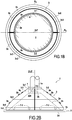
D'autres caractéristiques et avantages de la présente invention apparaîtront à la lumière de la description qui va suivre, qui se réfère aux dessins annexés et qui illustre sans aucun caractère limitatif des modes préférentiels de réalisation de l'invention :- la
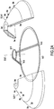
- la
figure 2B est une vue montrant un deuxième mode de fixation au mat la et/ou au radier 2c des deux deuxièmes caissons 3-1 et 3-2, combiné à blocage dans la direction verticale avecun épaulement 7 ; - la
figure 3 montre en coupe horizontale selon AA d'un deuxième caisson 3-1 comprenant des 3compartiments internes 3i séparés par deux cloisons verticales 3j disposées radialement équipés de vannes 3b débouchant sur l'extérieur ; - la
figure 4 représente une vue en coupe vertical axial dupremier caisson 2 montrant un compartiment central vide avec des parois latérales tronconique 2a, supérieure 2b et inférieure 2c ; - la
figure 5A montre une embase 1 flottant ensurface 10 en coupe verticale avec les deuxièmes caissons 3-1 et 3-2 et le compartiment central 2i vides ; - la
figure 5B montre la descente au fond de la mer de l'embase avec un ballastage complet du compartiment central 2i du premier caisson et ballastage partiel des deuxièmes caissons 3-1, 3-2 ; - la
figure 5C montre une embase 1 après sa dépose au fond de lamer 11, en cours de ballastage avant démontage, puis déballastage et récupération après démontage des deuxièmes caissons 3-1 et 3-2 ; - la
figure 6 montre une embase au fond de la mer après démontage des deuxièmes caissons et pose de l'éolienne 12 au sommet d'une cavité tubulaire 1a.
- each said second box comprising an inner surface conforming to the shape of the portion of said outer surface of the first block or box facing which it is applied, said second boxes being arranged in such a way that all of said second boxes cover the totality of said lateral external surface, each said second box comprising at least one valve opening on the outside,
- the distance (d) between said inner surfaces and outer surfaces of said second boxes is less than 1/3, preferably 1/5 to 1/3, of their height in the axial direction ZZ '.
Other features and advantages of the present invention will emerge in the light of the description which follows, which refers to the appended drawings and which illustrates, without any limiting character, the preferred embodiments of the invention:
- the
Figure 2B is a view showing a second mode of attachment to the mat and / or thefloor 2c of the two second boxes 3-1 and 3-2, combined blocking in the vertical direction with ashoulder 7; - the
figure 3 shows in horizontal section along AA of a second box 3-1 comprising 3internal compartments 3i separated by twovertical partitions 3j arranged radially equipped withvalves 3b opening on the outside; - the
figure 4 represents an axial vertical sectional view of thefirst caisson 2 showing an empty central compartment with frustoconicallateral walls 2a, upper 2b and lower 2c; - the
Figure 5A shows a base 1 floating in thesurface 10 in vertical section with the second boxes 3-1 and 3-2 and thecentral compartment 2i empty; - the
Figure 5B shows the descent to the bottom of the sea of the base with a full ballast of thecentral compartment 2i of the first caisson and partial ballasting of the second caissons 3-1, 3-2; - the
Figure 5C shows a base 1 after its removal to the bottom of thesea 11, being ballasted before disassembly, then deballasting and recovery after disassembly of the second caissons 3-1 and 3-2; - the
figure 6 shows a base at the bottom of the sea after disassembly of the second boxes and installation of thewind turbine 12 at the top of atubular cavity 1a.
Sur la
Sur la
Dans tous les modes de réalisation, ledit premier caisson 2 est entouré de deuxièmes caissons de flottabilité et ballastage 3, 3-1, et 3-2 en acier.In all embodiments, said
Dans un premier mode de réalisation de l'invention décrite dans les
- une surface supérieure demi-cylindrique verticale 3d apte à épouser une demi-circonférence du mat la et à reposer sur la demi surface annulaire de la plateforme supérieure 2b du
premier caisson 2 via un joint d'étanchéité dei semi-circulaire 5-1 décrit ci-après, et - une surface inférieure annulaire
plate 3e reposant sur le rebord périphérique plat annulaire 2c constituant la surface supérieure du radier 2c s'étendant sur une demi circonférence de celui-ci, coopérant avec celui-ci via un deuxième joint d'étanchéité semi-circulaire 5-2 ; et - une
surface latérale interne 3a etsurface latérale externe 3c assurant la liaison entre les extrémités des surfaces 3d et 3e.
- a vertical semi-cylindrical
upper surface 3d capable of conforming to a half-circumference of the mat and resting on the annular half surface of theupper platform 2b of thefirst box 2 via a semicircular seal 5-1 described herein. -after, and - a flat lower
annular bottom surface 3 resting on the annular flatperipheral flange 2c constituting the upper surface of theraft 2c extending over a half circumference thereof, cooperating therewith via a second semicircular seal 5 2; and - an inner
lateral surface 3a and outerlateral surface 3c ensuring the connection between the ends of thesurfaces
Les deux deuxièmes caissons 3-1 et 3-2 sont de même forme et disposés symétriquement par rapport à un plan P1 passant par l'axe ZZ' de la surface tronconique latérale 2a du premier caisson 2 et du mat 1a.The two second boxes 3-1 and 3-2 are of the same shape and arranged symmetrically with respect to a plane P1 passing through the axis ZZ 'of the lateral
Cette disposition des deuxièmes caissons 3-1 et 3-2 est avantageuse en ce qu'elle présente un recouvrement maximal du premier caisson 2 tout en facilitant la fixation des deuxièmes caissons 3-1 et 3-2 à la surface du premier caisson 2.This arrangement of the second caissons 3-1 and 3-2 is advantageous in that it has a maximum overlap of the
En effet, la forme semi tronconique des parois des deuxièmes caissons 3-1, 3-2 leur permet de pouvoir flotter dans une position verticale appropriée pour être déplacés en flottaison et assemblés symétriquement autour et contre le premier caisson sans l'aide d'une grue. En outre, du fait que la combinaison des deux deuxièmes caissons 3-1 et 3-2 recouvre entièrement la surface externe du premier caisson 2, il suffit de maintenir entre chaque deuxième caisson 3-1 et 3-2 et la surface externe du premier caisson 2, une dépression en pompant l'air de l'espace intercalaire 4 entre les joints 5 d'une part et les surface interne 3a et surface externe 2a pour réaliser une fixation entre lesdits deuxièmes caissons 3-1 et 3-2 et ledit bloc ou premier caisson 2 par simple dépression d'air.Indeed, the semi-frustoconical shape of the walls of the second caissons 3-1, 3-2 allows them to float in a position vertical suitable to be moved in flotation and assembled symmetrically around and against the first box without the help of a crane. In addition, because the combination of the two second boxes 3-1 and 3-2 completely covers the outer surface of the
Sur la
- un joint circulaire supérieur 5-1 au niveau du rebord plat périphérique d'une plateforme supérieure 2b, et
- un joint circulaire inférieur 5-2 de plus grand diamètre posant au niveau du rebord plat périphérique inférieur du radier 2c, et
- deux joints latéraux 5-3 disposés dans des plans radiaux passant par l'axe ZZ' et assurant la jonction entre le joint circulaire supérieur 5-1 et le joint circulaire inférieur 5-2 avec deux paires de joints latéraux 5-3 disposées diamétralement opposées.
- an upper circular seal 5-1 at the flat peripheral edge of an
upper platform 2b, and - a lower circular joint 5-2 of larger diameter posing at the level of the lower peripheral flat rim of the
slab 2c, and - two lateral joints 5-3 arranged in radial planes passing through the axis ZZ 'and ensuring the junction between the upper circular joint 5-1 and the lower circular joint 5-2 with two pairs of lateral joints 5-3 arranged diametrically opposite .
Ainsi, la face interne 3a de chacun des deux caissons 3-1, 3-2 repose sur :
- une partie semi-circulaire de joint supérieur 5-1 au niveau dudit rebord plat périphérique supérieur 2b, et
- une partie semi-circulaire de joint inférieur 5-2 au niveau dudit rebord plat périphérique inférieur 2d, et
- deux parties de joint latérales 5-3, disposées de préférence dans des plans radiaux l'axe de révolution ZZ' du premier bloc ou premier caisson, chaque dite partie de joint latérale 5-3 s'étendant depuis une extrémité de la partie semi-circulaire de joint supérieur 5-1 jusqu'à une extrémité de la partie semi-circulaire de joint inférieur située du même côté par à un plan de symétrie dudit deuxième caisson passant par l'axe de révolution ZZ' du premier bloc ou premier caisson.
- a semicircular portion of upper seal 5-1 at said upper peripheral
flat flange 2b, and - a semicircular portion of lower seal 5-2 at said lower peripheral
flat flange 2d, and - two lateral joint parts 5-3, preferably arranged in radial planes the axis of revolution ZZ 'of the first block or first box, each said side seam part 5-3 extending from one end of the semi-circular part; 5-1 upper joint ring to one end of the semicircular lower seal portion located in the same side by a plane of symmetry of said second box passing through the axis of revolution ZZ 'of the first block or first box.
Ce joint 5 délimite donc deux espaces intercalaires 4 entre les faces internes 3a de chacun des deux deuxièmes caissons 3-1 et 3-2 et la face externe du premier bloc ou premier caisson 2.This seal 5 thus delimits two
On comprend que les deux parties de joint latérales 5-3 sont disposées symétriquement par rapport à un plan de symétrie dudit deuxième caisson 3-1, 3-2 passant par l'axe de révolution ZZ' du premier caisson 2.It will be understood that the two lateral joint portions 5-3 are arranged symmetrically with respect to a plane of symmetry of said second box 3-1, 3-2 passing through the axis of revolution ZZ 'of the
Ainsi, une fois l'immersion de l'embase réalisée et son installation au fond de la mer, il est facile, par déballastage des deuxièmes caissons 3-1 et 3-2 d'une part, et d'autre part par remise à la pression de l'espace intercalaire 4 de faire remonter et récupérer en surface en flottaison les deuxième caisson 3-1 et 3-2.Thus, once the immersion of the base carried out and its installation at the bottom of the sea, it is easy, by déballastage second caissons 3-1 and 3-2 on the one hand, and on the other hand by delivery to the pressure of the
Les extrémités des surface cylindrique 3d et surface annulaire 3e, les plus proches de la surface externe du bloc ou premier caisson 2 sont réunies entre elles par une surface latérale interne 3a semi-tronconique, de même forme que la partie de la surface externe latérale tronconique 2a du premier caisson 2 en vis-à-vis de laquelle elle est appliquée. De même, les extrémités des surface cylindrique 3d et surface annulaire 3e les plus éloignées du premier caisson 2 sont réunies entre elles par une surface de révolution formant une surface latérale externe 3c du deuxième caisson 3 comprenant des parties de forme semi-tronconique en vis-à-vis de la partie semi-tronconique de la surface latérale interne 3a.The ends of the
Plus précisément, sur les
- une dite surface supérieure semi-cylindrique 3d s'étendant entre une première surface supérieure plate horizontale semi- annulaire 3d1 et une deuxième surface supérieure plate horizontale semi- annulaire 3d2, cette dernière étant apte à reposer sur ladite surface semi-annulaire de la plateforme supérieure 2b du premier caisson, et
- ladite
surface latérale interne 3a tronconique assure la jonction entre le bord externe 3a1 de ladite deuxième surface semi-annulaire 3d2 et le bord interne semi circulaire 3e1 de la surface inférieure semi-annulaire 3e, et - le bord externe semi-circulaire 3e2 de la surface inférieure semi-annulaire 3e est surmontée d'une surface inférieure semi-cylindrique verticale 3e3, et
- ladite
surface latérale externe 3c tronconique assure la jonction entre le bord externe 3c1 de ladite première surface semi-annulaire 3d1 et le bord externe semi-circulaire 3c1 de ladite première surface supérieure plate horizontale semi-annulaire 3d1 et le bord supérieure semi-circulaire 3c2 de ladite surface inférieure semi-cylindrique verticale 3e3.
- a said semi-cylindrical
upper surface 3d extending between a first semi-annular horizontal flat upper surface 3d1 and a second horizontal semi-annular flat upper surface 3d2, the latter being able to rest on said semi-annular surface of theupper platform 2b of the first box, and - said frustoconical internal
lateral surface 3a provides the junction between the outer edge 3a1 of said second semi-annular surface 3d2 and the semi-circular inner edge 3e1 of thelower semi-annular surface 3e, and - the semicircular outer edge 3e2 of the semi-annular
lower surface 3e is surmounted by a vertical semi-cylindrical lower surface 3e3, and - said frustoconical outer
lateral surface 3c provides the junction between the outer edge 3c1 of said first semi-annular surface 3d1 and the semicircular outer edge 3c1 of said first horizontal semi-annular flat upper surface 3d1 and the semicircular upper edge 3c2 of said vertical semi-cylindrical lower surface 3e3.
Sur les
- une partie supérieure tronconique entre ledit bord externe 3c1 de ladite première surface semi-annulaire 3d1 et une limite semi-circulaire intermédiaire 3c3 à mi-hauteur de l'embase, et
- une partie inférieure tronconique entre le bord semi-circulaire 3c2 de ladite surface inférieure semi-cylindrique verticale 3e3 et ladite limite semi-circulaire intermédiaire 3c3.
- a frustoconical upper portion between said outer edge 3c1 of said first semi-annular surface 3d1 and an intermediate semicircular limit 3c3 halfway up the base, and
- a frustoconical lower portion between the semi-circular edge 3c2 of said vertical semi-cylindrical lower surface 3e3 and said intermediate semi-circular boundary 3c3.
L'angle d'inclinaison α3 de la partie inférieure tronconique de ladite surface latérale externe 3c de chaque deuxième caisson par rapport à l'horizontale est supérieure à l'angle d'inclinaison α1 de la partie supérieure tronconique de ladite surface latérale externe 3c par rapport à l'horizontale. Et l'angle d'inclinaison α2 de la surface latérale interne 3a tronconique est intermédiaire compris entre α1 et α3.The angle of inclination α3 of the frustoconical lower part of said external
Les surface latérale externe 3c et surface latérale interne 3a du deuxième caisson 3 sont espacées d'une distance d inférieure à une valeur correspondant à environ 1/5 à 1/3, notamment environ 1/4 de la hauteur h de la surface latérale tronconique 2a du premier caisson 2.The external
L'intercalation des joints d'étanchéité 5-1 et 5-2 permet de ménager un espace intercalaire 4 de largeur de 1 à 10 cm entre la surface externe latérale 2a du premier caisson 2 et la surface interne 3a du deuxième caisson 3.The intercalation of the seals 5-1 and 5-2 makes it possible to provide an
Sur la
Dans un mode de réalisation, le premier caisson 2 représente typiquement une masse de 1000T à 7000T à vide (et 2 à 3 fois plus une fois rempli d'eau) correspondant à une hauteur h de 4 à 20 m et un diamètre inférieur de la surface 2d reposant au fond de la mer de 20 à 60m et un diamètre de la, plateforme supérieur 2b de 5 à 12 m.In one embodiment, the
Plus particulièrement, lesdits deuxièmes caissons de flottabilité et ballastage sont de dimensions et poids suivants :
- poids de 200 à 2000T,
- hauteur, h=3 à 30 m,
- distance d entre les faces
interne 3a etexterne 3c de 1 à 5m, - grand diamètre inférieur externe: de 20 à 80 m,
- petit diamètre supérieur de 5 à 25m.
- weight from 200 to 2000T,
- height, h = 3 to 30 m,
- distance d between the
inner faces 3a and outer 3c of 1 to 5m, - large external lower diameter: from 20 to 80 m,
- small diameter greater than 5 to 25m.
Sur la
Chaque compartiment interne 3i est équipé de préférence d'une pluralité de vannes 3b ouvrant sur l'extérieur, de préférence de différents diamètres, pour permettre pour la moitié des vannes, un ballastage lent et contrôlé durant la phase d'immersion et pour l'autre moitié des vannes un déballastage plus rapide pour le démontage et la récupération des deuxièmes caissons 3-1, 3-2, une fois l'embase posée au fond de la mer.Each
Pour ce faire, les vannes 3b, 2k et 4a du premier caisson 2 et des deuxièmes caissons 3-1, 3-2 sont connectés à un réseau de tuyaux souples 8 reliés à un bateau d'assistance 9 disposant de pompe dans le but de désolidariser les deuxièmes caissons 3-1, 3-2 pour les récupérer et déballaster lesdits deuxièmes caissons 3-1, 3-2 après désolidarisation de la surface externe du bloc ou premier caisson 2.To do this, the
Du fait de la multiplicité des compartiments 3i, les effets de carène liquide ne sont plus suffisamment déstabilisants et la multiplicité des compartiments 3i permet de contrôler l'assiette, la gite et le tirant d'eau de manière parfaitement ajustée des deuxièmes caissons 3-1 et 3-2 pour venir enveloppé la surface externe du bloc ou premier caisson 2 sans moyen de grutage. La séquence d'installation desdits deuxièmes caissons 3-1 et 3-2 et la mise en place de la structure au fond de la mer est donc réalisée uniquement en pilotant et en contrôlant le remplissage des différents compartiments 3i des deuxièmes caissons 3-1 et 3-2. De même, ce mode de réalisation permet d'obtenir une très bonne stabilité de l'embase gravitaire 1 durant toutes les phases d'immersion.Due to the multiplicity of the
Sur la
Sur la
Sur la
L'ouverture des vannes 3b et 2k peut être réalisée via des câbles de commande 8a et l'alimentation en eau et en air peut se faire via des tuyaux 8b pour les vannes 3b et 8c pour les vannes 4a pour l'espace 4. Ces câbles de pilotage et tuyaux d'alimentation ou évacuation/ aspiration sont reliés à des moyens de pompage sur le pont d'un navire d'assistance en surface 9 comme représenté sur la
Une fois arrivés au fond de la mer, les deuxièmes caissons 3-1, 3-2 peuvent avantageusement rester partiellement vides et le compartiment 2i est entièrement rempli d'eau. A ce moment, le cas échéant, on remplit entièrement d'eau les deuxièmes caissons. Une fois pleins, on peut les déconnecter et commencer le vidage partiel des deuxièmes caissons 3-1 et 3-2, le compartiment central 2i restant rempli d'eau. Du fait que les deuxièmes caissons sont pleins, ils deviennent pesants sur le premier caisson 2 de sorte que les fixations mécaniques 7-1, 7-2 ne sont plus en traction au moment de la libération des deuxièmes caissons ce qui permet de mieux contrôler leur remontée par déballastage après déconnection.Once at the bottom of the sea, the second boxes 3-1, 3-2 can advantageously remain partially empty and the
Lorsque les deuxièmes caissons sont fixés par dépression dans l'espace intercalaire 4, pour déconnecter les deuxièmes caissons 3-1, 3-2 on rétablit l'espace intercalaire 4 à la pression en envoyant de l'air par un tuyau 8c vers une vanne 4a depuis le navire d'assistance 9 ce qui permet - après leur déballastage - de récupérer les deuxièmes caissons 3-1 et 3-2 en surface en flottaison et ne laisser au fond de la mer que le bloc 2 supportant l'éolienne 12 comme représenté
Claims (14)
- A method of transporting an undersea structure for supporting and anchoring offshore equipment, preferably a wind turbine, and for depositing it on the sea bottom, said undersea support and anchoring structure comprising a gravity base (1) comprising a first solid block or a first hollow caisson (2) filled with ballast means and that rests on the sea bottom (11) and provides anchoring by virtue of its weight; said gravity first block or caisson (2) having a top outer surface (2b) supporting a column and/or a top device (1a) suitable for receiving the base of the pylon (12a) of a wind turbine (12), a plane bottom surface (2d) suitable for resting on the sea bottom, and a preferably leakproof outside surface (2a), in which method the following steps are performed:a) stowing said base (1) while fitted with buoyancy elements; and thenb) lowering said base to the sea bottom;and wherein:- before step a), a plurality of hollow buoyancy and ballasting second caissons (3-1, 3-2) are releasably fastened on the outside surface (2a, 2b, 2c) of said gravity first block or first caisson (2); and- in step a), at least some of said second caissons (3, 3-1, 3-2) are emptied at least in part; and- in step b), sea water is added into said second caissons (3, 3-1, 3-2) in order to lower said base (1) down to the sea bottom (11), with said second caissons (3, 3-1, 3-2) preferably remaining filled only in part with sea water; and- after step b), said second caissons (3, 3-1, 3-2) are separated and emptied, preferably progressively, so as to raise them to the surface (10) by buoyancy, preferably progressively;the method being characterized in that:- a plurality of said second caissons (3-1, 3-2) having the same shape and the same dimensions are fastened on an outside surface (2a) of frustoconical shape of the first block or first caisson (2) in a symmetrical distribution relative to a plane of symmetry of said first block or caisson and containing the axis of revolution (ZZ') of the first block or first caisson, the outside surfaces (3c) and the inside surfaces (3a) of said second caissons defining surfaces of revolution of frustoconical shape having the same axis of revolution (ZZ') as said outside surface of said first block or first caisson (2);- each said second caisson having an inside surface (3a) matching the shape of the facing portion of said outside surface (2a, 2b, 2c) of the first block or caisson (2) against which it is applied, said second caissons (3-1, 3-2) being arranged in such a manner that together said second caissons cover all of said outside surface (2a), each said second caisson (3-1, 3-2) having at least one valve (3b) opening to the outside; and- the distance (d) between said inside and outside surfaces (3a, 3b) of said second caissons is less than 1/3 of their height in the direction of their height (h) in the axial direction ZZ'; and- in step b), the base is lowered by controlling solely the filling of said second caissons.
- A method according to claim 1, characterized in that in step b), the base is lowered by controlling solely the filling of said second caissons, to the exclusion of any other controlled ballasting of said base and/or to the exclusion of any thruster.
- A method according to claim 1 or claim 2, characterized in that, at the end of step b), once said base has been placed on the sea bottom, said second caisson(s) remain(s) only partially filled with sea water.
- A method according to any one of claims 1 to 3, characterized in that the distance (d) between said inside and outside surfaces (3a, 3b) of said second caissons lies in the range 1/5 to 1/3 of their height (h) in the axial direction ZZ'.
- A method according to any one of claims 1 to 4, characterized in that:- in step a), said second caissons (3, 3-1, 3-2) are fastened against the first block or first caisson (2) while leaving an in-between space (4) between the inside face (3a) of each second caisson and the outside surface (2a) of the first block or first caisson (2), said in-between space (4) being sealed by at least one gasket (5, 5-1, 5-2), and suction (6) is established in said in-between space in order to fasten said second caisson against said first caisson; and- after step b), said second caissons are separated by returning said in-between space (4) to the external hydrostatic pressure.
- A method according to any one of claims 1 to 5, characterized in that said first block or first caisson (2) has a frustoconical outside surface (2a) with a raft (2c) constituting a bottom peripheral flat rim at its base and a flat top surface forming a top peripheral flat rim (2b) around a column and/or a tubular cavity (1a) for supporting a pylon (12a).
- A method according to any one of claims 1 to 6, characterized in that two second caissons (3-1, 3-2) are fastened, each covering substantially half of said frustoconical outside surface of said first block or first caisson, the inside face (3a) of each second caisson (3-1, 3-2) co-operating in sealed fastening against the first block or first caisson (2) with at least one peripheral gasket (5) comprising:- a semi-circular top gasket portion (5-1) at said top peripheral flat rim (2b); and- a semi-circular bottom gasket portion (5-2) at said bottom peripheral flat rim (2b); and- two side gasket portions (5-3) preferably arranged in planes radial relative to the axis of revolution ZZ' of the first block or first caisson, each said side gasket portion (5-3) extending from one end at the top semi-circular gasket portion (5-1) to an end at the bottom semi-circular gasket portion situated on the same side relative to a plane of symmetry (P1) of said second caisson containing the axis of revolution ZZ' of the first block or first caisson.
- A method according to any one of claims 1 to 7, characterized in that at least some of said second caissons (3-1, 3-2) comprise a respective plurality of internal compartments (3i) partitioned by separating partitions (3k), with each compartment being independent.
- A method according to any one of claims 1 to 8, characterized in that said second caissons (3, 3-1, 3-2) and/or the partitioned internal compartments (3i) of said second caissons are provided with valves (3b) opening to the outside, preferably with a plurality of valves of different diameters for said second caissons and/or for said second internal compartments (3i).
- A method according to any one of claims 1 to 9, characterized in that said second caissons and/or partitioned internal compartments of said second caissons are deballasted using pumping means on a service vessel (9) connected to flexible pipes (8).
- A method according to any one of claims 1 to 10, characterized in that said first block or first caisson (2) has a single internal compartment (2i).
- A method according to any one of claims 1 to 11, characterized in that said first block or first caisson (2) is filled with water during immersion in step b), said internal compartment (2i) being open to the outside and filling naturally with water during immersion.
- An undersea support and anchoring structure comprising a gravity base (1) comprising a first solid block or a first hollow caisson (2) filled at least in part with ballast means, preferably water, resting on the sea bottom (11), and providing anchoring by means of its weight; said gravity first block or first caisson (2) having a top surface (2b) supporting a column and/or a top device (1a) suitable for receiving the base of the pylon (12a) of a wind turbine (12), a plane bottom surface (2c) suitable for resting on the sea bottom, and a preferably leakproof outside surface (2a), the structure being suitable for use in a method according to any one of claims 1 to 12 and being characterized in that it comprises a plurality of said second caissons (3-1, 3-2) having the same shape and the same dimensions that are fastened to said first block or caisson on an outside surface (2a) of frustoconical shape of the first block or first caisson (2) in a symmetrical distribution relative to a plane of symmetry of said first block or caisson containing the axis of revolution ZZ' of the first block or first caisson, the outside surfaces (3c) and the inside surfaces (3a) of said second caissons defining surfaces of revolution of frustoconical shape about the same axis of revolution (ZZ') as said outside surface of said first block or first caisson (2);- each said second caisson having an inside surface (3a) matching the shape of the facing portion of said outside surface (2a, 2b, 2c) of the first block or caisson (2) against which it is applied, said second caissons (3-1, 3-2) being arranged in such a manner that said second caissons together cover all of said outside surface (2a), each said second caisson (3-1, 3-2) including at least one valve (3b) opening to the outside;- the distance (d) between said inside surfaces (3a) and outside surfaces (3c) of said second caissons is less than 1/3, preferably lying in the range 1/5 to 1/3, of their height (h) in the axial direction ZZ'.
- An undersea structure according to claim 13, characterized in that said first block or first caisson and said second caissons are such as defined in any one of claims 7 to 9 and 11.
Applications Claiming Priority (2)
| Application Number | Priority Date | Filing Date | Title |
|---|---|---|---|
| FR1551373A FR3032682B1 (en) | 2015-02-18 | 2015-02-18 | MARITIME WIND TURBINE SUPPORT AND ANCHOR STRUCTURE OF THE GRAVITY EMBASE TYPE AND METHOD OF TOWING AND REMOVING AT SEA |
| PCT/FR2016/050346 WO2016132059A1 (en) | 2015-02-18 | 2016-02-16 | Gravity-base-type structure for supporting and anchoring an offshore wind turbine, and method for towing and installing same in the sea |
Publications (2)
| Publication Number | Publication Date |
|---|---|
| EP3259404A1 EP3259404A1 (en) | 2017-12-27 |
| EP3259404B1 true EP3259404B1 (en) | 2018-12-05 |
Family
ID=52829170
Family Applications (1)
| Application Number | Title | Priority Date | Filing Date |
|---|---|---|---|
| EP16714960.8A Active EP3259404B1 (en) | 2015-02-18 | 2016-02-16 | Gravity-base-type structure for supporting and anchoring an offshore wind turbine, and method for towing and installing same in the sea |
Country Status (5)
| Country | Link |
|---|---|
| EP (1) | EP3259404B1 (en) |
| DK (1) | DK3259404T3 (en) |
| ES (1) | ES2712978T3 (en) |
| FR (1) | FR3032682B1 (en) |
| WO (1) | WO2016132059A1 (en) |
Cited By (1)
| Publication number | Priority date | Publication date | Assignee | Title |
|---|---|---|---|---|
| US20220112738A1 (en) * | 2019-10-31 | 2022-04-14 | Nabrawind Technologies, S.L | Transition piece for wind turbine tower |
Families Citing this family (3)
| Publication number | Priority date | Publication date | Assignee | Title |
|---|---|---|---|---|
| IT202000022255A1 (en) * | 2020-09-22 | 2022-03-22 | Mirco Armando Raffuzzi | PLATFORM ANCHORING SYSTEM |
| GB2604909A (en) | 2021-03-18 | 2022-09-21 | Subsea 7 Ltd | Subsea foundations |
| CN116084371B (en) * | 2023-02-02 | 2024-05-24 | 中国电建集团贵阳勘测设计研究院有限公司 | Offshore wind power installation platform |
Family Cites Families (7)
| Publication number | Priority date | Publication date | Assignee | Title |
|---|---|---|---|---|
| FI107184B (en) | 1999-11-11 | 2001-06-15 | Asko Fagerstroem | Procedure and arrangement for installing an offshore wind turbine at sea and / or retrieving it from the sea and an offshore wind turbine |
| FR2827015B1 (en) | 2001-07-06 | 2005-12-23 | Bouygues Offshore | OFFSHORE WIND TURBINE AND METHOD OF CONSTRUCTION |
| NO315898B1 (en) | 2001-11-21 | 2003-11-10 | Mpu Entpr As | Ballastable lifting vessel and method for using a ballastable lifting vessel for lifting, transporting, positioning and installation of at least ± nmarin construction, preferably ± n or more wind turbines |
| FR2923454B1 (en) * | 2007-11-09 | 2010-01-15 | Freyssinet | METHOD OF TRANSPORTING AQUATIC ENVIRONMENT OF A CIVIL WORK |
| NO328838B1 (en) * | 2008-06-20 | 2010-05-25 | Seatower As | Device and method of wind generator |
| FR2948092B1 (en) | 2009-07-15 | 2015-01-23 | Saipem Sa | CATAMARAN-TYPE BOAT USEFUL FOR ASSEMBLY, TRANSPORT AND REMOVAL AT THE BOTTOM OF THE MARITIME WINDWATER SEA |
| GB2481258A (en) * | 2010-06-19 | 2011-12-21 | Peter Ronald Chambers | A submersible dynamic floatation tank mountable to a base of an offshore wind turbine assembly |
-
2015
- 2015-02-18 FR FR1551373A patent/FR3032682B1/en active Active
-
2016
- 2016-02-16 DK DK16714960.8T patent/DK3259404T3/en active
- 2016-02-16 ES ES16714960T patent/ES2712978T3/en active Active
- 2016-02-16 EP EP16714960.8A patent/EP3259404B1/en active Active
- 2016-02-16 WO PCT/FR2016/050346 patent/WO2016132059A1/en active Application Filing
Non-Patent Citations (1)
| Title |
|---|
| None * |
Cited By (2)
| Publication number | Priority date | Publication date | Assignee | Title |
|---|---|---|---|---|
| US20220112738A1 (en) * | 2019-10-31 | 2022-04-14 | Nabrawind Technologies, S.L | Transition piece for wind turbine tower |
| US11767682B2 (en) * | 2019-10-31 | 2023-09-26 | Nabrawind Technologies, S.L | Transition piece for wind turbine tower |
Also Published As
| Publication number | Publication date |
|---|---|
| DK3259404T3 (en) | 2019-04-01 |
| WO2016132059A1 (en) | 2016-08-25 |
| FR3032682A1 (en) | 2016-08-19 |
| EP3259404A1 (en) | 2017-12-27 |
| ES2712978T3 (en) | 2019-05-17 |
| FR3032682B1 (en) | 2018-08-17 |
Similar Documents
| Publication | Publication Date | Title |
|---|---|---|
| EP3717343B1 (en) | Floating support structure for offshore wind turbine and method for installing a wind turbine provided with such a support structure | |
| EP2441893B1 (en) | Support device for a wind turbine for producing electric power at sea, corresponding facility for producing electric power at sea. | |
| EP2454149B1 (en) | Catamaran ship used for assembling, transporting and installing a marine wind turbine on the seafloor | |
| EP3259404B1 (en) | Gravity-base-type structure for supporting and anchoring an offshore wind turbine, and method for towing and installing same in the sea | |
| EP2454471B1 (en) | Marine wind turbine having a pylon vertically adjusted by setting | |
| EP1581703B1 (en) | Method for offshore installation of a wind turbine | |
| CA1305370C (en) | Modular system for the production, storage and loading of hydrocarbons at sea | |
| FR2827015A1 (en) | OFFSHORE WIND TURBINE AND ITS CONSTRUCTION METHOD | |
| FR2935679A1 (en) | FLOATING SUPPORT COMPRISING A TURRET EQUIPPED WITH TWO MOORING MOORINGS OF ANCHOR LINES AND DOWN / SURFACE BONDING PIPES | |
| EP2495162A1 (en) | Transport vessel of a wind turbine to an offshore site and method for its implementation | |
| FR2887900A1 (en) | Electricity generating system constructing and installing method, involves towing assembly of ballast, system and structure to site, maintaining descended structure on sea-bed and resetting cans in flotation after detaching, to be reused | |
| FR2935005A1 (en) | SEAT STRUCTURE OF A HYDRAULIC TURBOMACHINE | |
| EP2906818A1 (en) | V-shaped, bi-rotor wind generator on a spar floating structure | |
| EP1606160B1 (en) | Device and method for stabilising and controlling the lowering or raising of a heavy structure between the surface and the bed of the sea | |
| EP3652056A1 (en) | Mooring for anchoring a floating structure | |
| FR2894646A1 (en) | Offshore liquefied natural or petroleum gas terminal comprises storage tanks and auxiliary chambers of a size such that they can be installed by flotation on a base | |
| FR3035455A1 (en) | FLOATING SUPPORT WITH VARIABLE HORIZONTAL SECTION WITH DEPTH | |
| WO2016132056A1 (en) | Lattice-tower-type structure for supporting and anchoring an offshore wind turbine, and method for towing and installing same in the sea | |
| FR3119367A1 (en) | Floating platform, associated disassembly and assembly processes | |
| CA1281555C (en) | Semi-submersible platform, namely for subseau deposit exploration and/or exploitation in cold waters | |
| FR2864586A1 (en) | Ocean wave vertical energy capturing device for hydroelectric turbine, has rectangular floating platform buoy subjected to oscillation-pivoting inclinations around its vertical axis by oscillations of roll and pitch of ocean wave | |
| FR2645827A1 (en) | Marine platform formed of a plurality of modular elements for storing products and for direct anchoring and loading of ships, and method for installing, dismantling and reinstalling this platform at another location | |
| WO2014009514A2 (en) | Facility for storing compressed gases under water and corresponding installation method | |
| FR2463847A1 (en) | Underwater structure - has base and buoyant tower connected by universal joint and sealed flexible tunnels | |
| BE825465A (en) | PROCESS FOR THE STORAGE OF OIL FROM SUBMARINE WELLS AND FOR THE TRANSFER OF OIL INTO AND FROM OIL TANKERS AND APPARATUS FOR STORAGE AND DISTRIBUTION OF OIL TO BE USED WITH SUCH A PROCESS |
Legal Events
| Date | Code | Title | Description |
|---|---|---|---|
| STAA | Information on the status of an ep patent application or granted ep patent |
Free format text: STATUS: THE INTERNATIONAL PUBLICATION HAS BEEN MADE |
|
| PUAI | Public reference made under article 153(3) epc to a published international application that has entered the european phase |
Free format text: ORIGINAL CODE: 0009012 |
|
| STAA | Information on the status of an ep patent application or granted ep patent |
Free format text: STATUS: REQUEST FOR EXAMINATION WAS MADE |
|
| 17P | Request for examination filed |
Effective date: 20170818 |
|
| AK | Designated contracting states |
Kind code of ref document: A1 Designated state(s): AL AT BE BG CH CY CZ DE DK EE ES FI FR GB GR HR HU IE IS IT LI LT LU LV MC MK MT NL NO PL PT RO RS SE SI SK SM TR |
|
| AX | Request for extension of the european patent |
Extension state: BA ME |
|
| DAV | Request for validation of the european patent (deleted) | ||
| DAX | Request for extension of the european patent (deleted) | ||
| GRAP | Despatch of communication of intention to grant a patent |
Free format text: ORIGINAL CODE: EPIDOSNIGR1 |
|
| STAA | Information on the status of an ep patent application or granted ep patent |
Free format text: STATUS: GRANT OF PATENT IS INTENDED |
|
| INTG | Intention to grant announced |
Effective date: 20180605 |
|
| GRAS | Grant fee paid |
Free format text: ORIGINAL CODE: EPIDOSNIGR3 |
|
| GRAJ | Information related to disapproval of communication of intention to grant by the applicant or resumption of examination proceedings by the epo deleted |
Free format text: ORIGINAL CODE: EPIDOSDIGR1 |
|
| GRAL | Information related to payment of fee for publishing/printing deleted |
Free format text: ORIGINAL CODE: EPIDOSDIGR3 |
|
| STAA | Information on the status of an ep patent application or granted ep patent |
Free format text: STATUS: REQUEST FOR EXAMINATION WAS MADE |
|
| GRAR | Information related to intention to grant a patent recorded |
Free format text: ORIGINAL CODE: EPIDOSNIGR71 |
|
| STAA | Information on the status of an ep patent application or granted ep patent |
Free format text: STATUS: GRANT OF PATENT IS INTENDED |
|
| GRAA | (expected) grant |
Free format text: ORIGINAL CODE: 0009210 |
|
| STAA | Information on the status of an ep patent application or granted ep patent |
Free format text: STATUS: THE PATENT HAS BEEN GRANTED |
|
| INTC | Intention to grant announced (deleted) | ||
| RIC1 | Information provided on ipc code assigned before grant |
Ipc: F03D 13/20 20160101ALI20181018BHEP Ipc: F03D 13/10 20160101ALI20181018BHEP Ipc: B63B 35/44 20060101ALI20181018BHEP Ipc: E02B 17/00 20060101ALI20181018BHEP Ipc: B63B 35/00 20060101ALI20181018BHEP Ipc: E02B 17/02 20060101AFI20181018BHEP Ipc: E02D 27/52 20060101ALI20181018BHEP |
|
| AK | Designated contracting states |
Kind code of ref document: B1 Designated state(s): AL AT BE BG CH CY CZ DE DK EE ES FI FR GB GR HR HU IE IS IT LI LT LU LV MC MK MT NL NO PL PT RO RS SE SI SK SM TR |
|
| INTG | Intention to grant announced |
Effective date: 20181022 |
|
| REG | Reference to a national code |
Ref country code: GB Ref legal event code: FG4D Free format text: NOT ENGLISH |
|
| REG | Reference to a national code |
Ref country code: CH Ref legal event code: EP |
|
| REG | Reference to a national code |
Ref country code: AT Ref legal event code: REF Ref document number: 1073238 Country of ref document: AT Kind code of ref document: T Effective date: 20181215 |
|
| REG | Reference to a national code |
Ref country code: IE Ref legal event code: FG4D Free format text: LANGUAGE OF EP DOCUMENT: FRENCH |
|
| REG | Reference to a national code |
Ref country code: DE Ref legal event code: R096 Ref document number: 602016007871 Country of ref document: DE |
|
| REG | Reference to a national code |
Ref country code: DE Ref legal event code: R082 Ref document number: 602016007871 Country of ref document: DE Representative=s name: CBDL PATENTANWAELTE, DE |
|
| REG | Reference to a national code |
Ref country code: DK Ref legal event code: T3 Effective date: 20190325 |
|
| REG | Reference to a national code |
Ref country code: AT Ref legal event code: MK05 Ref document number: 1073238 Country of ref document: AT Kind code of ref document: T Effective date: 20181205 |
|
| REG | Reference to a national code |
Ref country code: NL Ref legal event code: FP |
|
| REG | Reference to a national code |
Ref country code: LT Ref legal event code: MG4D |
|
| PG25 | Lapsed in a contracting state [announced via postgrant information from national office to epo] |
Ref country code: FI Free format text: LAPSE BECAUSE OF FAILURE TO SUBMIT A TRANSLATION OF THE DESCRIPTION OR TO PAY THE FEE WITHIN THE PRESCRIBED TIME-LIMIT Effective date: 20181205 Ref country code: LT Free format text: LAPSE BECAUSE OF FAILURE TO SUBMIT A TRANSLATION OF THE DESCRIPTION OR TO PAY THE FEE WITHIN THE PRESCRIBED TIME-LIMIT Effective date: 20181205 Ref country code: BG Free format text: LAPSE BECAUSE OF FAILURE TO SUBMIT A TRANSLATION OF THE DESCRIPTION OR TO PAY THE FEE WITHIN THE PRESCRIBED TIME-LIMIT Effective date: 20190305 Ref country code: HR Free format text: LAPSE BECAUSE OF FAILURE TO SUBMIT A TRANSLATION OF THE DESCRIPTION OR TO PAY THE FEE WITHIN THE PRESCRIBED TIME-LIMIT Effective date: 20181205 Ref country code: LV Free format text: LAPSE BECAUSE OF FAILURE TO SUBMIT A TRANSLATION OF THE DESCRIPTION OR TO PAY THE FEE WITHIN THE PRESCRIBED TIME-LIMIT Effective date: 20181205 Ref country code: NO Free format text: LAPSE BECAUSE OF FAILURE TO SUBMIT A TRANSLATION OF THE DESCRIPTION OR TO PAY THE FEE WITHIN THE PRESCRIBED TIME-LIMIT Effective date: 20190305 Ref country code: AT Free format text: LAPSE BECAUSE OF FAILURE TO SUBMIT A TRANSLATION OF THE DESCRIPTION OR TO PAY THE FEE WITHIN THE PRESCRIBED TIME-LIMIT Effective date: 20181205 |
|
| REG | Reference to a national code |
Ref country code: ES Ref legal event code: FG2A Ref document number: 2712978 Country of ref document: ES Kind code of ref document: T3 Effective date: 20190517 |
|
| PG25 | Lapsed in a contracting state [announced via postgrant information from national office to epo] |
Ref country code: AL Free format text: LAPSE BECAUSE OF FAILURE TO SUBMIT A TRANSLATION OF THE DESCRIPTION OR TO PAY THE FEE WITHIN THE PRESCRIBED TIME-LIMIT Effective date: 20181205 Ref country code: GR Free format text: LAPSE BECAUSE OF FAILURE TO SUBMIT A TRANSLATION OF THE DESCRIPTION OR TO PAY THE FEE WITHIN THE PRESCRIBED TIME-LIMIT Effective date: 20190306 Ref country code: RS Free format text: LAPSE BECAUSE OF FAILURE TO SUBMIT A TRANSLATION OF THE DESCRIPTION OR TO PAY THE FEE WITHIN THE PRESCRIBED TIME-LIMIT Effective date: 20181205 Ref country code: SE Free format text: LAPSE BECAUSE OF FAILURE TO SUBMIT A TRANSLATION OF THE DESCRIPTION OR TO PAY THE FEE WITHIN THE PRESCRIBED TIME-LIMIT Effective date: 20181205 |
|
| PG25 | Lapsed in a contracting state [announced via postgrant information from national office to epo] |
Ref country code: PT Free format text: LAPSE BECAUSE OF FAILURE TO SUBMIT A TRANSLATION OF THE DESCRIPTION OR TO PAY THE FEE WITHIN THE PRESCRIBED TIME-LIMIT Effective date: 20190405 Ref country code: CZ Free format text: LAPSE BECAUSE OF FAILURE TO SUBMIT A TRANSLATION OF THE DESCRIPTION OR TO PAY THE FEE WITHIN THE PRESCRIBED TIME-LIMIT Effective date: 20181205 Ref country code: IT Free format text: LAPSE BECAUSE OF FAILURE TO SUBMIT A TRANSLATION OF THE DESCRIPTION OR TO PAY THE FEE WITHIN THE PRESCRIBED TIME-LIMIT Effective date: 20181205 Ref country code: PL Free format text: LAPSE BECAUSE OF FAILURE TO SUBMIT A TRANSLATION OF THE DESCRIPTION OR TO PAY THE FEE WITHIN THE PRESCRIBED TIME-LIMIT Effective date: 20181205 |
|
| PG25 | Lapsed in a contracting state [announced via postgrant information from national office to epo] |
Ref country code: SK Free format text: LAPSE BECAUSE OF FAILURE TO SUBMIT A TRANSLATION OF THE DESCRIPTION OR TO PAY THE FEE WITHIN THE PRESCRIBED TIME-LIMIT Effective date: 20181205 Ref country code: RO Free format text: LAPSE BECAUSE OF FAILURE TO SUBMIT A TRANSLATION OF THE DESCRIPTION OR TO PAY THE FEE WITHIN THE PRESCRIBED TIME-LIMIT Effective date: 20181205 Ref country code: IS Free format text: LAPSE BECAUSE OF FAILURE TO SUBMIT A TRANSLATION OF THE DESCRIPTION OR TO PAY THE FEE WITHIN THE PRESCRIBED TIME-LIMIT Effective date: 20190405 Ref country code: SM Free format text: LAPSE BECAUSE OF FAILURE TO SUBMIT A TRANSLATION OF THE DESCRIPTION OR TO PAY THE FEE WITHIN THE PRESCRIBED TIME-LIMIT Effective date: 20181205 Ref country code: EE Free format text: LAPSE BECAUSE OF FAILURE TO SUBMIT A TRANSLATION OF THE DESCRIPTION OR TO PAY THE FEE WITHIN THE PRESCRIBED TIME-LIMIT Effective date: 20181205 |
|
| REG | Reference to a national code |
Ref country code: DE Ref legal event code: R097 Ref document number: 602016007871 Country of ref document: DE |
|
| REG | Reference to a national code |
Ref country code: CH Ref legal event code: PL |
|
| PLBE | No opposition filed within time limit |
Free format text: ORIGINAL CODE: 0009261 |
|
| STAA | Information on the status of an ep patent application or granted ep patent |
Free format text: STATUS: NO OPPOSITION FILED WITHIN TIME LIMIT |
|
| PG25 | Lapsed in a contracting state [announced via postgrant information from national office to epo] |
Ref country code: SI Free format text: LAPSE BECAUSE OF FAILURE TO SUBMIT A TRANSLATION OF THE DESCRIPTION OR TO PAY THE FEE WITHIN THE PRESCRIBED TIME-LIMIT Effective date: 20181205 Ref country code: MC Free format text: LAPSE BECAUSE OF FAILURE TO SUBMIT A TRANSLATION OF THE DESCRIPTION OR TO PAY THE FEE WITHIN THE PRESCRIBED TIME-LIMIT Effective date: 20181205 Ref country code: LU Free format text: LAPSE BECAUSE OF NON-PAYMENT OF DUE FEES Effective date: 20190216 |
|
| 26N | No opposition filed |
Effective date: 20190906 |
|
| REG | Reference to a national code |
Ref country code: IE Ref legal event code: MM4A |
|
| PG25 | Lapsed in a contracting state [announced via postgrant information from national office to epo] |
Ref country code: LI Free format text: LAPSE BECAUSE OF NON-PAYMENT OF DUE FEES Effective date: 20190228 Ref country code: CH Free format text: LAPSE BECAUSE OF NON-PAYMENT OF DUE FEES Effective date: 20190228 |
|
| PG25 | Lapsed in a contracting state [announced via postgrant information from national office to epo] |
Ref country code: IE Free format text: LAPSE BECAUSE OF NON-PAYMENT OF DUE FEES Effective date: 20190216 |
|
| PG25 | Lapsed in a contracting state [announced via postgrant information from national office to epo] |
Ref country code: TR Free format text: LAPSE BECAUSE OF FAILURE TO SUBMIT A TRANSLATION OF THE DESCRIPTION OR TO PAY THE FEE WITHIN THE PRESCRIBED TIME-LIMIT Effective date: 20181205 |
|
| PG25 | Lapsed in a contracting state [announced via postgrant information from national office to epo] |
Ref country code: MT Free format text: LAPSE BECAUSE OF FAILURE TO SUBMIT A TRANSLATION OF THE DESCRIPTION OR TO PAY THE FEE WITHIN THE PRESCRIBED TIME-LIMIT Effective date: 20181205 |
|
| PG25 | Lapsed in a contracting state [announced via postgrant information from national office to epo] |
Ref country code: CY Free format text: LAPSE BECAUSE OF FAILURE TO SUBMIT A TRANSLATION OF THE DESCRIPTION OR TO PAY THE FEE WITHIN THE PRESCRIBED TIME-LIMIT Effective date: 20181205 |
|
| PG25 | Lapsed in a contracting state [announced via postgrant information from national office to epo] |
Ref country code: HU Free format text: LAPSE BECAUSE OF FAILURE TO SUBMIT A TRANSLATION OF THE DESCRIPTION OR TO PAY THE FEE WITHIN THE PRESCRIBED TIME-LIMIT; INVALID AB INITIO Effective date: 20160216 |
|
| PG25 | Lapsed in a contracting state [announced via postgrant information from national office to epo] |
Ref country code: MK Free format text: LAPSE BECAUSE OF FAILURE TO SUBMIT A TRANSLATION OF THE DESCRIPTION OR TO PAY THE FEE WITHIN THE PRESCRIBED TIME-LIMIT Effective date: 20181205 |
|
| REG | Reference to a national code |
Ref country code: DE Ref legal event code: R082 Ref document number: 602016007871 Country of ref document: DE Representative=s name: CBDL PATENTANWAELTE GBR, DE |
|
| P01 | Opt-out of the competence of the unified patent court (upc) registered |
Effective date: 20230517 |
|
| PGFP | Annual fee paid to national office [announced via postgrant information from national office to epo] |
Ref country code: NL Payment date: 20240129 Year of fee payment: 9 |
|
| PGFP | Annual fee paid to national office [announced via postgrant information from national office to epo] |
Ref country code: ES Payment date: 20240306 Year of fee payment: 9 |
|
| PGFP | Annual fee paid to national office [announced via postgrant information from national office to epo] |
Ref country code: DE Payment date: 20240213 Year of fee payment: 9 Ref country code: GB Payment date: 20240221 Year of fee payment: 9 |
|
| PGFP | Annual fee paid to national office [announced via postgrant information from national office to epo] |
Ref country code: FR Payment date: 20240221 Year of fee payment: 9 Ref country code: DK Payment date: 20240129 Year of fee payment: 9 Ref country code: BE Payment date: 20240226 Year of fee payment: 9 |