EP3258525A1 - Fuel processing apparatus for fuel cell, and fuel cell system - Google Patents
Fuel processing apparatus for fuel cell, and fuel cell system Download PDFInfo
- Publication number
- EP3258525A1 EP3258525A1 EP15882109.0A EP15882109A EP3258525A1 EP 3258525 A1 EP3258525 A1 EP 3258525A1 EP 15882109 A EP15882109 A EP 15882109A EP 3258525 A1 EP3258525 A1 EP 3258525A1
- Authority
- EP
- European Patent Office
- Prior art keywords
- reactor
- pipe
- burner
- fuel
- cooling medium
- Prior art date
- Legal status (The legal status is an assumption and is not a legal conclusion. Google has not performed a legal analysis and makes no representation as to the accuracy of the status listed.)
- Granted
Links
Images


Classifications
-
- H—ELECTRICITY
- H01—ELECTRIC ELEMENTS
- H01M—PROCESSES OR MEANS, e.g. BATTERIES, FOR THE DIRECT CONVERSION OF CHEMICAL ENERGY INTO ELECTRICAL ENERGY
- H01M8/00—Fuel cells; Manufacture thereof
- H01M8/06—Combination of fuel cells with means for production of reactants or for treatment of residues
- H01M8/0606—Combination of fuel cells with means for production of reactants or for treatment of residues with means for production of gaseous reactants
- H01M8/0612—Combination of fuel cells with means for production of reactants or for treatment of residues with means for production of gaseous reactants from carbon-containing material
- H01M8/0618—Reforming processes, e.g. autothermal, partial oxidation or steam reforming
-
- H—ELECTRICITY
- H01—ELECTRIC ELEMENTS
- H01M—PROCESSES OR MEANS, e.g. BATTERIES, FOR THE DIRECT CONVERSION OF CHEMICAL ENERGY INTO ELECTRICAL ENERGY
- H01M8/00—Fuel cells; Manufacture thereof
- H01M8/04—Auxiliary arrangements, e.g. for control of pressure or for circulation of fluids
-
- C—CHEMISTRY; METALLURGY
- C01—INORGANIC CHEMISTRY
- C01B—NON-METALLIC ELEMENTS; COMPOUNDS THEREOF; METALLOIDS OR COMPOUNDS THEREOF NOT COVERED BY SUBCLASS C01C
- C01B3/00—Hydrogen; Gaseous mixtures containing hydrogen; Separation of hydrogen from mixtures containing it; Purification of hydrogen; Reversible storage of hydrogen
- C01B3/02—Production of hydrogen; Production of gaseous mixtures containing hydrogen
- C01B3/32—Production of hydrogen; Production of gaseous mixtures containing hydrogen by reaction of gaseous or liquid organic compounds with gasifying agents, e.g. water, carbon dioxide or air
- C01B3/34—Production of hydrogen; Production of gaseous mixtures containing hydrogen by reaction of gaseous or liquid organic compounds with gasifying agents, e.g. water, carbon dioxide or air by reaction of hydrocarbons with gasifying agents
- C01B3/48—Production of hydrogen; Production of gaseous mixtures containing hydrogen by reaction of gaseous or liquid organic compounds with gasifying agents, e.g. water, carbon dioxide or air by reaction of hydrocarbons with gasifying agents followed by reaction of water vapour with carbon monoxide
-
- H—ELECTRICITY
- H01—ELECTRIC ELEMENTS
- H01M—PROCESSES OR MEANS, e.g. BATTERIES, FOR THE DIRECT CONVERSION OF CHEMICAL ENERGY INTO ELECTRICAL ENERGY
- H01M8/00—Fuel cells; Manufacture thereof
- H01M8/04—Auxiliary arrangements, e.g. for control of pressure or for circulation of fluids
- H01M8/04082—Arrangements for control of reactant parameters, e.g. pressure or concentration
- H01M8/04089—Arrangements for control of reactant parameters, e.g. pressure or concentration of gaseous reactants
-
- H—ELECTRICITY
- H01—ELECTRIC ELEMENTS
- H01M—PROCESSES OR MEANS, e.g. BATTERIES, FOR THE DIRECT CONVERSION OF CHEMICAL ENERGY INTO ELECTRICAL ENERGY
- H01M8/00—Fuel cells; Manufacture thereof
- H01M8/06—Combination of fuel cells with means for production of reactants or for treatment of residues
-
- H—ELECTRICITY
- H01—ELECTRIC ELEMENTS
- H01M—PROCESSES OR MEANS, e.g. BATTERIES, FOR THE DIRECT CONVERSION OF CHEMICAL ENERGY INTO ELECTRICAL ENERGY
- H01M8/00—Fuel cells; Manufacture thereof
- H01M8/06—Combination of fuel cells with means for production of reactants or for treatment of residues
- H01M8/0662—Treatment of gaseous reactants or gaseous residues, e.g. cleaning
- H01M8/0668—Removal of carbon monoxide or carbon dioxide
-
- C—CHEMISTRY; METALLURGY
- C01—INORGANIC CHEMISTRY
- C01B—NON-METALLIC ELEMENTS; COMPOUNDS THEREOF; METALLOIDS OR COMPOUNDS THEREOF NOT COVERED BY SUBCLASS C01C
- C01B2203/00—Integrated processes for the production of hydrogen or synthesis gas
- C01B2203/02—Processes for making hydrogen or synthesis gas
- C01B2203/0205—Processes for making hydrogen or synthesis gas containing a reforming step
- C01B2203/0227—Processes for making hydrogen or synthesis gas containing a reforming step containing a catalytic reforming step
- C01B2203/0233—Processes for making hydrogen or synthesis gas containing a reforming step containing a catalytic reforming step the reforming step being a steam reforming step
-
- C—CHEMISTRY; METALLURGY
- C01—INORGANIC CHEMISTRY
- C01B—NON-METALLIC ELEMENTS; COMPOUNDS THEREOF; METALLOIDS OR COMPOUNDS THEREOF NOT COVERED BY SUBCLASS C01C
- C01B2203/00—Integrated processes for the production of hydrogen or synthesis gas
- C01B2203/02—Processes for making hydrogen or synthesis gas
- C01B2203/0283—Processes for making hydrogen or synthesis gas containing a CO-shift step, i.e. a water gas shift step
-
- C—CHEMISTRY; METALLURGY
- C01—INORGANIC CHEMISTRY
- C01B—NON-METALLIC ELEMENTS; COMPOUNDS THEREOF; METALLOIDS OR COMPOUNDS THEREOF NOT COVERED BY SUBCLASS C01C
- C01B2203/00—Integrated processes for the production of hydrogen or synthesis gas
- C01B2203/04—Integrated processes for the production of hydrogen or synthesis gas containing a purification step for the hydrogen or the synthesis gas
- C01B2203/0435—Catalytic purification
- C01B2203/044—Selective oxidation of carbon monoxide
-
- C—CHEMISTRY; METALLURGY
- C01—INORGANIC CHEMISTRY
- C01B—NON-METALLIC ELEMENTS; COMPOUNDS THEREOF; METALLOIDS OR COMPOUNDS THEREOF NOT COVERED BY SUBCLASS C01C
- C01B2203/00—Integrated processes for the production of hydrogen or synthesis gas
- C01B2203/04—Integrated processes for the production of hydrogen or synthesis gas containing a purification step for the hydrogen or the synthesis gas
- C01B2203/0465—Composition of the impurity
- C01B2203/047—Composition of the impurity the impurity being carbon monoxide
-
- C—CHEMISTRY; METALLURGY
- C01—INORGANIC CHEMISTRY
- C01B—NON-METALLIC ELEMENTS; COMPOUNDS THEREOF; METALLOIDS OR COMPOUNDS THEREOF NOT COVERED BY SUBCLASS C01C
- C01B2203/00—Integrated processes for the production of hydrogen or synthesis gas
- C01B2203/06—Integration with other chemical processes
- C01B2203/066—Integration with other chemical processes with fuel cells
-
- C—CHEMISTRY; METALLURGY
- C01—INORGANIC CHEMISTRY
- C01B—NON-METALLIC ELEMENTS; COMPOUNDS THEREOF; METALLOIDS OR COMPOUNDS THEREOF NOT COVERED BY SUBCLASS C01C
- C01B2203/00—Integrated processes for the production of hydrogen or synthesis gas
- C01B2203/08—Methods of heating or cooling
- C01B2203/0805—Methods of heating the process for making hydrogen or synthesis gas
- C01B2203/0811—Methods of heating the process for making hydrogen or synthesis gas by combustion of fuel
- C01B2203/0816—Heating by flames
-
- C—CHEMISTRY; METALLURGY
- C01—INORGANIC CHEMISTRY
- C01B—NON-METALLIC ELEMENTS; COMPOUNDS THEREOF; METALLOIDS OR COMPOUNDS THEREOF NOT COVERED BY SUBCLASS C01C
- C01B2203/00—Integrated processes for the production of hydrogen or synthesis gas
- C01B2203/08—Methods of heating or cooling
- C01B2203/0872—Methods of cooling
- C01B2203/0883—Methods of cooling by indirect heat exchange
-
- C—CHEMISTRY; METALLURGY
- C01—INORGANIC CHEMISTRY
- C01B—NON-METALLIC ELEMENTS; COMPOUNDS THEREOF; METALLOIDS OR COMPOUNDS THEREOF NOT COVERED BY SUBCLASS C01C
- C01B2203/00—Integrated processes for the production of hydrogen or synthesis gas
- C01B2203/10—Catalysts for performing the hydrogen forming reactions
- C01B2203/1041—Composition of the catalyst
- C01B2203/1076—Copper or zinc-based catalysts
-
- C—CHEMISTRY; METALLURGY
- C01—INORGANIC CHEMISTRY
- C01B—NON-METALLIC ELEMENTS; COMPOUNDS THEREOF; METALLOIDS OR COMPOUNDS THEREOF NOT COVERED BY SUBCLASS C01C
- C01B2203/00—Integrated processes for the production of hydrogen or synthesis gas
- C01B2203/12—Feeding the process for making hydrogen or synthesis gas
- C01B2203/1205—Composition of the feed
- C01B2203/1211—Organic compounds or organic mixtures used in the process for making hydrogen or synthesis gas
- C01B2203/1235—Hydrocarbons
- C01B2203/1247—Higher hydrocarbons
-
- C—CHEMISTRY; METALLURGY
- C01—INORGANIC CHEMISTRY
- C01B—NON-METALLIC ELEMENTS; COMPOUNDS THEREOF; METALLOIDS OR COMPOUNDS THEREOF NOT COVERED BY SUBCLASS C01C
- C01B2203/00—Integrated processes for the production of hydrogen or synthesis gas
- C01B2203/16—Controlling the process
- C01B2203/1604—Starting up the process
-
- Y—GENERAL TAGGING OF NEW TECHNOLOGICAL DEVELOPMENTS; GENERAL TAGGING OF CROSS-SECTIONAL TECHNOLOGIES SPANNING OVER SEVERAL SECTIONS OF THE IPC; TECHNICAL SUBJECTS COVERED BY FORMER USPC CROSS-REFERENCE ART COLLECTIONS [XRACs] AND DIGESTS
- Y02—TECHNOLOGIES OR APPLICATIONS FOR MITIGATION OR ADAPTATION AGAINST CLIMATE CHANGE
- Y02E—REDUCTION OF GREENHOUSE GAS [GHG] EMISSIONS, RELATED TO ENERGY GENERATION, TRANSMISSION OR DISTRIBUTION
- Y02E60/00—Enabling technologies; Technologies with a potential or indirect contribution to GHG emissions mitigation
- Y02E60/30—Hydrogen technology
- Y02E60/50—Fuel cells
Definitions
- the present invention relates to a fuel processing apparatus for supplying hydrogen to a fuel cell and a fuel cell system having the same.
- a fuel cell which produces electricity by allowing hydrogen to chemically react with oxygen in the air, is a high-efficiency next-generation energy source that emits neither pollutants nor noise and may be permanently used as long as hydrogen is consistently supplied.
- a fuel cell system broadly includes the fuel cell, and a fuel processing apparatus for supplying hydrogen to the fuel cell.
- a typical fuel processing apparatus includes a reforming reactor which converts a gas mixture of a vapor and a raw material for power generation into hydrogen, a burner which supplies heat to the reforming reactor, and a water gas reactor and a partial oxidation reactor which reduce concentration of carbon monoxide (CO) in reformed gas discharged from the reforming reactor.
- concentration of carbon monoxide of the reformed gas treated by the water gas reactor and the partial oxidation reactor is about 50 ppm or lower.
- the water-gas shift reaction (CO + H 2 O ⁇ CO 2 + H 2 ) in the water gas reactor is an exothermic reaction that releases heat. Because the water gas reactor needs to maintain a constant reaction temperature to obtain a large effect of reducing CO, piping is typically installed on an outer wall of the water gas reactor and a cooling medium is supplied to the piping to prevent overheating.
- the cooling medium inhibits an increase in temperature when the water gas reactor starts up, and as a result, a startup time is increased, and overall efficiency of the fuel cell system deteriorates in a case in which heat, which is absorbed from the water gas reactor by the cooling medium, is discharged to the outside.
- heat which is absorbed from the water gas reactor by the cooling medium
- there is a temperature deviation between the outer wall and the interior of the water gas reactor due to the cooling medium and as a result, the efficiency in reducing CO is decreased as the temperature deviation is increased.
- the present invention has been made in an effort to provide a fuel processing apparatus for a fuel cell, which prevents overheating of a water gas reactor by using a cooling medium, in which a startup time for the water gas reactor may be decreased, overall efficiency of the fuel cell system may be increased by reusing heat absorbed from the water gas reactor, and efficiency in reducing CO may be increased by reducing a temperature deviation of the water gas reactor, and to provide a fuel cell system having the fuel processing apparatus.
- An exemplary embodiment of the present invention provides a fuel processing apparatus for a fuel cell, including: a reforming reactor; a burner; a water gas reactor; and a valve.
- the reforming reactor produces reformed gas from a gas mixture of water and a raw material for power generation.
- the burner supplies heat to the reforming reactor.
- the water gas reactor includes a reactor main body which is supplied with the reformed gas from the reforming reactor and reduces concentration of carbon monoxide in the reformed gas, and a cooling flow path which is installed in the reactor main body.
- the valve controls a supply of a cooling medium to the cooling flow path while distinguishing a startup and a normal operation of the water gas reactor.
- the burner may be supplied with burner fuel and burner air through a fuel pipe and an air pipe, and the cooling medium may be the burner air supplied to the burner.
- the cooling flow path may be connected to a supply pipe and a discharge pipe outside the reactor main body.
- the supply pipe may be connected to the air pipe, and the discharge pipe may be connected to any one of the air pipe and the fuel pipe.
- the valve may be a 3-way valve connected to the air pipe and the supply pipe, the valve may provide the cooling medium to the burner through the air pipe when the water gas reactor starts up, and the valve may provide the cooling medium to the cooling flow path through the supply pipe when the water gas reactor normally operates.
- a temperature of the cooling medium provided to the cooling flow path may be increased through heat exchange with the water gas reactor, and then the cooling medium may be provided to the burner through the discharge pipe.
- the reactor main body may have a catalyst therein.
- An inlet pipe and an outlet pipe for the reformed gas may be connected to an upper end of a sidewall and a lower end of the sidewall of the reactor main body that abut against the catalyst.
- the cooling flow path may include a first cover plate which covers an upper end of the catalyst, a second cover plate which covers a lower end of the catalyst, and a plurality of cooling pipes which is connected to the first cover plate and the second cover plate and penetrates the catalyst.
- the supply pipe and the discharge pipe for the cooling medium may be connected to lower and upper ends of the reactor main body.
- An edge of the first cover plate and an edge of the second cover plate may be sealed to prevent a leak of the reformed gas inputted to the catalyst.
- the fuel processing apparatus includes a reforming reactor, a burner, a water gas reactor, and a valve.
- the reforming reactor produces reformed gas from a gas mixture of water and a raw material for power generation.
- the burner supplies heat to the reforming reactor.
- the water gas reactor includes a reactor main body which is supplied with the reformed gas from the reforming reactor and reduces concentration of carbon monoxide in the reformed gas, and a cooling flow path which is installed in the reactor main body.
- the valve controls a supply of a cooling medium to the cooling flow path while distinguishing a startup and a normal operation of the water gas reactor.
- the burner may be supplied with burner fuel and burner air through a fuel pipe and an air pipe, and the cooling medium may be the burner air supplied to the burner.
- the cooling flow path may be connected to a supply pipe and a discharge pipe outside the reactor main body.
- the supply pipe may be connected to the air pipe, and the discharge pipe may be connected to any one of the air pipe and the fuel pipe.
- the valve may be a 3-way valve connected to the air pipe and the supply pipe, the valve may provide the cooling medium to the burner through the air pipe when the water gas reactor starts up, and the valve may provide the cooling medium to the cooling flow path through the supply pipe when the water gas reactor normally operates.
- a temperature of the cooling medium provided to the cooling flow path may be increased through heat exchange with the water gas reactor, and then the cooling medium may be provided to the burner through the discharge pipe.
- the reactor main body may have a catalyst therein.
- An inlet pipe and an outlet pipe for the reformed gas may be connected to a sidewall upper end and a sidewall lower end of the reactor main body that abut against the catalyst.
- the cooling flow path may include a first cover plate which covers an upper end of the catalyst, a second cover plate which covers a lower end of the catalyst, and a plurality of cooling pipes which is connected to the first cover plate and the second cover plate and penetrates the catalyst.
- the supply pipe and the discharge pipe for the cooling medium may be connected to lower and upper ends of the reactor main body.
- An edge of the first cover plate and an edge of the second cover plate may be sealed to prevent a leak of the reformed gas inputted to the catalyst.
- the exemplary embodiments of the present invention it is possible to decrease a startup time by cutting off a supply of the cooling medium to the cooling flow path of the water gas reactor when starting up the water gas reactor, and to prevent overheating of the water gas reactor by supplying the cooling medium to the cooling flow path when normally operating the water gas reactor.
- the cooling medium which is inputted into the cooling flow path and heated during the normal operation of the water gas reactor, is supplied to the burner instead of being discharged to the outside, and as a result, it is possible to reduce the usage amount of burner fuel, and to improve overall efficiency of the fuel cell system.
- the case includes not only a case where the part is present "immediately on” another part, but also a case where still another part is present therebetween.
- “one object is positioned on the other object” means that one object is positioned over or under the other object, but does not necessarily mean that one object is positioned over the other object based on the gravitational direction.
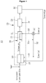
- FIG. 1 is a configuration view of a fuel cell system according to an exemplary embodiment of the present invention.
- a fuel cell system 100 includes a fuel cell 200, and a fuel processing apparatus 300 which supplies hydrogen to the fuel cell 200.
- the fuel processing apparatus 300 produces reformed gas, which contains a large amount of hydrogen, from a raw material for power generation and supplies the reformed gas to the fuel cell 200, and the fuel cell 200 allows the supplied hydrogen to chemically react with oxygen in the air, thereby producing electrical energy.
- the fuel processing apparatus 300 includes a reforming reactor 310 which converts a gas mixture of water (vapor) and a raw material for power generation into hydrogen, a burner 320 which supplies heat to the reforming reactor 310, a water gas reactor 330 which reduces concentration of carbon monoxide in the reformed gas discharged from the reforming reactor 310, and a valve 340 which controls a supply of a cooling medium in the water gas reactor 330.
- the fuel processing apparatus 300 may further include a partial oxidation reactor 350 connected to the water gas reactor 330.
- the raw material for power generation may be hydrocarbon-based fuel such as liquefied natural gas (LNG) or liquefied petroleum gas (LPG), and the reforming reactor 310 may be a vapor reforming reactor.
- the reforming reactor 310 reforms hydrocarbon in the raw material for power generation into hydrogen by allowing the hydrocarbon to react with oxygen under a high-temperature atmosphere. In this case, carbon monoxide CO is generated as a reaction by-product.
- the reforming reactor 310 discharges the reformed gas including hydrogen, carbon monoxide, and carbon dioxide, and the discharged reformed gas is inputted into the water gas reactor 330.
- the burner 320 supplies heat to the reforming reactor 310, and allows the reforming reactor 310 to maintain a high temperature required for the reforming reaction.
- the burner 320 is supplied with burner fuel (such as city gas) through a fuel pipe 361, and an air pipe 362 is connected to the fuel pipe 361.
- the burner 320 generates combustion heat by combusting burner fuel and burner air.
- the water gas reactor 330 converts carbon monoxide in the reformed gas into carbon dioxide by using a water-gas shift reaction.
- the water gas reactor 330 includes a reactor main body 331 having a catalyst therein.
- the catalyst may be configured from various catalysts such as a Cu-Zn based catalyst, a catalyst having a metal oxide carrier supported with platinum, and a catalyst including Cu and platinum-based metal.
- the fuel cell system 100 may become stable as the concentration of carbon monoxide is decreased in the water gas reactor 330.
- the partial oxidation reactor 350 is supplied with the reformed gas from the water gas reactor 330, reduces the concentration of carbon monoxide to 50 ppm or less, particularly, 10 ppm or less, and supplies the carbon monoxide to the fuel cell 200.
- Final reformed gas produced by the fuel processing apparatus 300 is supplied to the fuel cell 200 and used for power generation, and unreacted gas, which is discharged without being used for power generation, is supplied to the burner 320 and used to increase a temperature of the reforming reactor 310.
- the water gas reactor 330 requires a predetermined time (startup time) until the catalyst reaches a reaction temperature and the water gas reactor 330 normally operates when the fuel cell system 100 starts up.
- the water gas reactor 330 may include a heater (not illustrated) for decreasing the startup time. Further, the water gas reactor 330 continuously generates heat while normally operating, and carbon dioxide is converted back into carbon monoxide at a particular temperature or higher, and as a result, it is necessary to maintain a constant temperature by using the cooling medium.
- the water gas reactor 330 includes a cooling flow path 370 installed in the reactor main body 331.
- the cooling flow path 370 provides a closed flow path so that the cooling medium is not mixed with the reformed gas, and the cooling flow path 370 is connected to a supply pipe 363 and a discharge pipe 364 outside the reactor main body 331.
- the cooling medium which is inputted into the cooling flow path 370 through the supply pipe 363, exchanges heat with the catalyst such that a temperature of the cooling medium is increased, and then the cooling medium is discharged through the discharge pipe 364.
- the valve 340 is installed in the supply pipe 363 of the cooling flow path 370 and controls the supply of the cooling medium while distinguishing between the startup and the normal operation of the water gas reactor 330. Specifically, the valve 340 cuts off the supply of the cooling medium when the water gas reactor 330 starts up, thereby preventing the cooling medium from hindering an increase in temperature of the water gas reactor 330. In addition, the valve 340 supplies the cooling medium when the water gas reactor 330 normally operates, thereby allowing the water gas reactor 330 to maintain a constant temperature.
- the cooling medium hinders an increase in temperature of the water gas reactor 330, such that a long period of time is required until the catalyst reaches a reaction temperature. That is, the startup time is increased.
- the valve 340 supplies the cooling medium only when the water gas reactor 330 normally operates, and as a result, it is possible to decrease the startup time of the water gas reactor 330.
- the cooling medium which is inputted into the cooling flow path 370 and obtains heat from the water gas reactor 330 during the normal operation, is reused in the fuel cell system 100 without being discharged to the outside.
- the burner air which is supplied to the burner 320, may be used as a cooling medium for the water gas reactor 330.
- the valve 340 may be a 3-way valve connected to the air pipe 362 and the supply pipe 363 of the cooling flow path 370, and the discharge pipe 364 of the cooling flow path 370 is connected to the air pipe 362 or the fuel pipe 361.
- valve 340 closes the supply pipe 363 and opens the air pipe 362 to provide the cooling medium to the burner 320 through the air pipe 362. Thereafter, when the catalyst of the water gas reactor 330 reaches the reaction temperature and thus reaches a normal operating condition, the valve 340 closes the air pipe 362 and opens the supply pipe 363 to provide the cooling medium to the cooling flow path 370 through the supply pipe 363.
- the temperature of the cooling medium which is inputted into the cooling flow path 370, is increased through heat exchange with the water gas reactor 330, and the cooling medium (burner air) heated by the heat exchange is supplied to the burner 320. Since the heated burner air is supplied to the burner 320, the usage amount of the burner fuel may be reduced, which leads to an improvement in efficiency of the fuel cell system 100.
- city gas of 41 Nl/min and vapor of 125 cc/min may be supplied to the reforming reactor 310, and heat produced by the water gas reactor 330 may be -34.52 kJ/min.
- the cooling medium (burner air) of 200 Nl/min (25°C) may be supplied to the cooling flow path 370 during the normal operation of the water gas reactor 330, and a temperature of the cooling medium, which is discharged after reaction heat of the water gas reactor 330 is removed, may be about 155°C.
- the high-temperature air is supplied to the burner 320, and it is possible to save burner fuel of about 0.95 Nl/min as shown in the following relationship formula related to the amount of generated heat.
- the above reaction formula is a relationship formula related to the amount of heat generated by a reaction between methane and oxygen.
- the stepwise operating method which distinguishes the startup and the normal operation of the water gas reactor 330, is applied to the fuel processing apparatus 300 of the present exemplary embodiment, it is possible to decrease the startup time of the water gas reactor 330.
- the cooling medium heated through the heat exchange is supplied to the burner 320, such that the usage amount of the burner fuel is reduced, and as a result, it is possible to improve overall efficiency of the fuel cell system 100.
- FIG. 2 is a schematic cross-sectional view of the water gas reactor of the fuel cell system illustrated in FIG. 1
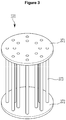
- FIG. 3 is a perspective view of the cooling flow path of the water gas reactor illustrated in FIG. 2 .
- the water gas reactor 330 includes the reactor main body 331 which has a catalyst 332 therein, and the cooling flow path 370 which is installed in the reactor main body 331.
- the catalyst 332 is positioned in the reactor main body 331 at a predetermined distance from upper and lower ends of the reactor main body 331.
- An inlet pipe 334 may be connected to an upper portion of a sidewall of the reactor main body 331 that abuts against the catalyst 332, and an outlet pipe 335 may be connected to a lower portion of the sidewall of the reactor main body 331 that abuts against the catalyst 332.
- the reformed gas discharged from the reforming reactor 310 is inputted to the reactor main body 331 through the inlet pipe 334, and carbon monoxide in the inputted reformed gas is converted into carbon dioxide through the water-gas shift reaction caused by the catalyst 332.
- the reformed gas with lowered concentration of carbon monoxide is discharged through the outlet pipe 335.
- the supply pipe 363 for the cooling medium may be connected to a center of a lower end of the reactor main body 331, and the discharge pipe 364 for the cooling medium may be connected to a center of an upper end of the reactor main body 331.
- the cooling flow path 370 includes a first cover plate 371 which covers an upper end of the catalyst 332, a second cover plate 372 which covers a lower end of the catalyst 332, and a plurality of cooling pipes 373 which is connected to the first cover plate 371 and the second cover plate 372 and penetrates the catalyst 332.
- the first cover plate 371 may be spaced apart from the upper end of the reactor main body 331, and the second cover plate 372 may be spaced apart from the lower end of the reactor main body 331. An edge of the first cover plate 371 and an edge of the second cover plate 372 are sealed to prevent the reformed gas, which is inputted to the catalyst 332, from leaking to the outside of the first and second cover plates 371 and 372.
- the plurality of cooling pipes 373 may be formed to have the same diameter, and the plurality of cooling pipes 373 may be disposed at an equal interval.
- Each of the first cover plate 371 and the second cover plate 372 is a porous plate formed with a plurality of openings, and opens end portions of the plurality of cooling pipes 373.
- the cooling medium which is inputted to the reactor main body 331 through the supply pipe 363, is distributed to the plurality of cooling pipes 373, and exchanges heat with the catalyst 332 while passing through the plurality of cooling pipes 373. Since the plurality of cooling pipes 373 penetrates the catalyst 332 in the reactor main body 331, the cooling medium supplied to the cooling flow path 370 may uniformly cool the catalyst 332. Therefore, it is possible to increase efficiency in reducing CO by decreasing a temperature deviation for each position of the catalyst 332.
- FIG. 2 illustrates a temperature distribution of the catalyst 332 by a dotted line.
- the temperature of the catalyst 332 is increased as a distance from the cooling flow path 370 is increased, and since the plurality of cooling pipes 373 penetrates the catalyst 332, the temperature deviation for each position of the catalyst 332 is not high.
- FIG. 4 is a cross-sectional view illustrating a water gas reactor of a Comparative Example.
- a water gas reactor 380 of the Comparative Example includes a reactor main body 331 which has a catalyst 332 therein, and a cooling flow path 385 which is installed on an outer wall of the reactor main body 331.
- the cooling flow path 385 is in the form of a coil wound around the reactor main body 331, and exhaust gas of a burner or water may be used as a cooling medium.
- FIG. 4 illustrates a temperature distribution of the catalyst 332 by a dotted line. Since the cooling medium abuts against the outer wall of the reactor main body 331 and exchanges heat with the reactor main body 331, a cooling effect of the cooling medium rarely affects a central portion of the catalyst 332. Therefore, the water gas reactor 380 of the Comparative Example has a high temperature deviation and low efficiency in reducing CO.
Landscapes
- Chemical & Material Sciences (AREA)
- Chemical Kinetics & Catalysis (AREA)
- Engineering & Computer Science (AREA)
- Life Sciences & Earth Sciences (AREA)
- Manufacturing & Machinery (AREA)
- Sustainable Development (AREA)
- Sustainable Energy (AREA)
- Electrochemistry (AREA)
- General Chemical & Material Sciences (AREA)
- Organic Chemistry (AREA)
- General Health & Medical Sciences (AREA)
- Combustion & Propulsion (AREA)
- Inorganic Chemistry (AREA)
- Health & Medical Sciences (AREA)
- Fuel Cell (AREA)
- Hydrogen, Water And Hydrids (AREA)
Abstract
Description
- The present invention relates to a fuel processing apparatus for supplying hydrogen to a fuel cell and a fuel cell system having the same.
- A fuel cell, which produces electricity by allowing hydrogen to chemically react with oxygen in the air, is a high-efficiency next-generation energy source that emits neither pollutants nor noise and may be permanently used as long as hydrogen is consistently supplied. A fuel cell system broadly includes the fuel cell, and a fuel processing apparatus for supplying hydrogen to the fuel cell.
- A typical fuel processing apparatus includes a reforming reactor which converts a gas mixture of a vapor and a raw material for power generation into hydrogen, a burner which supplies heat to the reforming reactor, and a water gas reactor and a partial oxidation reactor which reduce concentration of carbon monoxide (CO) in reformed gas discharged from the reforming reactor. The concentration of carbon monoxide of the reformed gas treated by the water gas reactor and the partial oxidation reactor is about 50 ppm or lower.
- The water-gas shift reaction (CO + H2O → CO2 + H2) in the water gas reactor is an exothermic reaction that releases heat. Because the water gas reactor needs to maintain a constant reaction temperature to obtain a large effect of reducing CO, piping is typically installed on an outer wall of the water gas reactor and a cooling medium is supplied to the piping to prevent overheating.
- However, the cooling medium inhibits an increase in temperature when the water gas reactor starts up, and as a result, a startup time is increased, and overall efficiency of the fuel cell system deteriorates in a case in which heat, which is absorbed from the water gas reactor by the cooling medium, is discharged to the outside. In addition, there is a temperature deviation between the outer wall and the interior of the water gas reactor due to the cooling medium, and as a result, the efficiency in reducing CO is decreased as the temperature deviation is increased.
- The present invention has been made in an effort to provide a fuel processing apparatus for a fuel cell, which prevents overheating of a water gas reactor by using a cooling medium, in which a startup time for the water gas reactor may be decreased, overall efficiency of the fuel cell system may be increased by reusing heat absorbed from the water gas reactor, and efficiency in reducing CO may be increased by reducing a temperature deviation of the water gas reactor, and to provide a fuel cell system having the fuel processing apparatus.
- An exemplary embodiment of the present invention provides a fuel processing apparatus for a fuel cell, including: a reforming reactor; a burner; a water gas reactor; and a valve. The reforming reactor produces reformed gas from a gas mixture of water and a raw material for power generation. The burner supplies heat to the reforming reactor. The water gas reactor includes a reactor main body which is supplied with the reformed gas from the reforming reactor and reduces concentration of carbon monoxide in the reformed gas, and a cooling flow path which is installed in the reactor main body. The valve controls a supply of a cooling medium to the cooling flow path while distinguishing a startup and a normal operation of the water gas reactor.
- The burner may be supplied with burner fuel and burner air through a fuel pipe and an air pipe, and the cooling medium may be the burner air supplied to the burner. The cooling flow path may be connected to a supply pipe and a discharge pipe outside the reactor main body. The supply pipe may be connected to the air pipe, and the discharge pipe may be connected to any one of the air pipe and the fuel pipe.
- The valve may be a 3-way valve connected to the air pipe and the supply pipe, the valve may provide the cooling medium to the burner through the air pipe when the water gas reactor starts up, and the valve may provide the cooling medium to the cooling flow path through the supply pipe when the water gas reactor normally operates. A temperature of the cooling medium provided to the cooling flow path may be increased through heat exchange with the water gas reactor, and then the cooling medium may be provided to the burner through the discharge pipe.
- The reactor main body may have a catalyst therein. An inlet pipe and an outlet pipe for the reformed gas may be connected to an upper end of a sidewall and a lower end of the sidewall of the reactor main body that abut against the catalyst.
- The cooling flow path may include a first cover plate which covers an upper end of the catalyst, a second cover plate which covers a lower end of the catalyst, and a plurality of cooling pipes which is connected to the first cover plate and the second cover plate and penetrates the catalyst. The supply pipe and the discharge pipe for the cooling medium may be connected to lower and upper ends of the reactor main body. An edge of the first cover plate and an edge of the second cover plate may be sealed to prevent a leak of the reformed gas inputted to the catalyst.
- Another exemplary embodiment of the present invention provides a fuel cell system including: a fuel cell; and a fuel processing apparatus which supplies the fuel cell with reformed gas containing hydrogen. The fuel processing apparatus includes a reforming reactor, a burner, a water gas reactor, and a valve. The reforming reactor produces reformed gas from a gas mixture of water and a raw material for power generation. The burner supplies heat to the reforming reactor. The water gas reactor includes a reactor main body which is supplied with the reformed gas from the reforming reactor and reduces concentration of carbon monoxide in the reformed gas, and a cooling flow path which is installed in the reactor main body. The valve controls a supply of a cooling medium to the cooling flow path while distinguishing a startup and a normal operation of the water gas reactor.
- The burner may be supplied with burner fuel and burner air through a fuel pipe and an air pipe, and the cooling medium may be the burner air supplied to the burner. The cooling flow path may be connected to a supply pipe and a discharge pipe outside the reactor main body. The supply pipe may be connected to the air pipe, and the discharge pipe may be connected to any one of the air pipe and the fuel pipe.
- The valve may be a 3-way valve connected to the air pipe and the supply pipe, the valve may provide the cooling medium to the burner through the air pipe when the water gas reactor starts up, and the valve may provide the cooling medium to the cooling flow path through the supply pipe when the water gas reactor normally operates. A temperature of the cooling medium provided to the cooling flow path may be increased through heat exchange with the water gas reactor, and then the cooling medium may be provided to the burner through the discharge pipe.
- The reactor main body may have a catalyst therein. An inlet pipe and an outlet pipe for the reformed gas may be connected to a sidewall upper end and a sidewall lower end of the reactor main body that abut against the catalyst.
- The cooling flow path may include a first cover plate which covers an upper end of the catalyst, a second cover plate which covers a lower end of the catalyst, and a plurality of cooling pipes which is connected to the first cover plate and the second cover plate and penetrates the catalyst. The supply pipe and the discharge pipe for the cooling medium may be connected to lower and upper ends of the reactor main body. An edge of the first cover plate and an edge of the second cover plate may be sealed to prevent a leak of the reformed gas inputted to the catalyst.
- According to the exemplary embodiments of the present invention, it is possible to decrease a startup time by cutting off a supply of the cooling medium to the cooling flow path of the water gas reactor when starting up the water gas reactor, and to prevent overheating of the water gas reactor by supplying the cooling medium to the cooling flow path when normally operating the water gas reactor.
- In addition, the cooling medium, which is inputted into the cooling flow path and heated during the normal operation of the water gas reactor, is supplied to the burner instead of being discharged to the outside, and as a result, it is possible to reduce the usage amount of burner fuel, and to improve overall efficiency of the fuel cell system.
-
-
FIG. 1 is a configuration view of a fuel cell system according to an exemplary embodiment of the present invention. -
FIG. 2 is a schematic cross-sectional view of a water gas reactor of the fuel cell system illustrated inFIG. 1 . -
FIG. 3 is a perspective view of a cooling flow path of the water gas reactor illustrated inFIG. 2 . -
FIG. 4 is a cross-sectional view illustrating a water gas reactor of a Comparative Example. - Hereinafter, the present invention will be described more fully hereinafter with reference to the accompanying drawings, in which example embodiments of the invention are shown. As those skilled in the art would realize, the described embodiments may be modified in various different ways, all without departing from the scope of the present invention.
- Further, in the present specification, when a part such as a layer, a film, a region, and a plate is present "on" or "at an upper portion of" another part, the case includes not only a case where the part is present "immediately on" another part, but also a case where still another part is present therebetween. Further, "one object is positioned on the other object" means that one object is positioned over or under the other object, but does not necessarily mean that one object is positioned over the other object based on the gravitational direction.
- Throughout the specification, unless explicitly described to the contrary, the word "comprise" and variations such as "comprises" or "comprising" will be understood to imply the inclusion of stated elements. The size and thickness of each component illustrated in the drawings are arbitrarily shown for understanding and ease of description, but the present invention is not limited thereto.
-
FIG. 1 is a configuration view of a fuel cell system according to an exemplary embodiment of the present invention. - Referring to
FIG. 1 , afuel cell system 100 includes afuel cell 200, and afuel processing apparatus 300 which supplies hydrogen to thefuel cell 200. Thefuel processing apparatus 300 produces reformed gas, which contains a large amount of hydrogen, from a raw material for power generation and supplies the reformed gas to thefuel cell 200, and thefuel cell 200 allows the supplied hydrogen to chemically react with oxygen in the air, thereby producing electrical energy. - The
fuel processing apparatus 300 includes a reformingreactor 310 which converts a gas mixture of water (vapor) and a raw material for power generation into hydrogen, aburner 320 which supplies heat to the reformingreactor 310, awater gas reactor 330 which reduces concentration of carbon monoxide in the reformed gas discharged from the reformingreactor 310, and avalve 340 which controls a supply of a cooling medium in thewater gas reactor 330. Thefuel processing apparatus 300 may further include apartial oxidation reactor 350 connected to thewater gas reactor 330. - The raw material for power generation may be hydrocarbon-based fuel such as liquefied natural gas (LNG) or liquefied petroleum gas (LPG), and the reforming
reactor 310 may be a vapor reforming reactor. The reformingreactor 310 reforms hydrocarbon in the raw material for power generation into hydrogen by allowing the hydrocarbon to react with oxygen under a high-temperature atmosphere. In this case, carbon monoxide CO is generated as a reaction by-product. A chemical reaction performed by the reformingreactor 310 is as follows.
Reaction 1 CH4 + H2O ↔ CO + 3H2 (ΔH298 = 205.813kJ/mol)
CO + H2O ↔ CO2 + H2 (ΔH298 = -41.15kJ/mol)
- The reforming
reactor 310 discharges the reformed gas including hydrogen, carbon monoxide, and carbon dioxide, and the discharged reformed gas is inputted into thewater gas reactor 330. - The
burner 320 supplies heat to the reformingreactor 310, and allows the reformingreactor 310 to maintain a high temperature required for the reforming reaction. Theburner 320 is supplied with burner fuel (such as city gas) through afuel pipe 361, and anair pipe 362 is connected to thefuel pipe 361. Theburner 320 generates combustion heat by combusting burner fuel and burner air. - The
water gas reactor 330 converts carbon monoxide in the reformed gas into carbon dioxide by using a water-gas shift reaction. Thewater gas reactor 330 includes a reactormain body 331 having a catalyst therein. The catalyst may be configured from various catalysts such as a Cu-Zn based catalyst, a catalyst having a metal oxide carrier supported with platinum, and a catalyst including Cu and platinum-based metal. A chemical reaction performed by thewater gas reactor 330 is as follows.
Reaction 2 CO + H2O ↔ CO2 + H2 (ΔH298 = -41.15kJ/mol)
- The
fuel cell system 100 may become stable as the concentration of carbon monoxide is decreased in thewater gas reactor 330. Thepartial oxidation reactor 350 is supplied with the reformed gas from thewater gas reactor 330, reduces the concentration of carbon monoxide to 50 ppm or less, particularly, 10 ppm or less, and supplies the carbon monoxide to thefuel cell 200. A chemical reaction performed by thepartial oxidation reactor 350 is as follows.
Reaction 3 CO +½O2 ↔ CO2 (ΔH298 = -282.984kJ/mol)
- Final reformed gas produced by the
fuel processing apparatus 300 is supplied to thefuel cell 200 and used for power generation, and unreacted gas, which is discharged without being used for power generation, is supplied to theburner 320 and used to increase a temperature of the reformingreactor 310. - The
water gas reactor 330 requires a predetermined time (startup time) until the catalyst reaches a reaction temperature and thewater gas reactor 330 normally operates when thefuel cell system 100 starts up. Thewater gas reactor 330 may include a heater (not illustrated) for decreasing the startup time. Further, thewater gas reactor 330 continuously generates heat while normally operating, and carbon dioxide is converted back into carbon monoxide at a particular temperature or higher, and as a result, it is necessary to maintain a constant temperature by using the cooling medium. - The
water gas reactor 330 includes acooling flow path 370 installed in the reactormain body 331. Thecooling flow path 370 provides a closed flow path so that the cooling medium is not mixed with the reformed gas, and thecooling flow path 370 is connected to asupply pipe 363 and adischarge pipe 364 outside the reactormain body 331. The cooling medium, which is inputted into thecooling flow path 370 through thesupply pipe 363, exchanges heat with the catalyst such that a temperature of the cooling medium is increased, and then the cooling medium is discharged through thedischarge pipe 364. - The
valve 340 is installed in thesupply pipe 363 of thecooling flow path 370 and controls the supply of the cooling medium while distinguishing between the startup and the normal operation of thewater gas reactor 330. Specifically, thevalve 340 cuts off the supply of the cooling medium when thewater gas reactor 330 starts up, thereby preventing the cooling medium from hindering an increase in temperature of thewater gas reactor 330. In addition, thevalve 340 supplies the cooling medium when thewater gas reactor 330 normally operates, thereby allowing thewater gas reactor 330 to maintain a constant temperature. - Assuming that the cooling medium is inputted at the same time of the startup of the
water gas reactor 330, the cooling medium hinders an increase in temperature of thewater gas reactor 330, such that a long period of time is required until the catalyst reaches a reaction temperature. That is, the startup time is increased. However, in thefuel processing apparatus 300 of the present exemplary embodiment, thevalve 340 supplies the cooling medium only when thewater gas reactor 330 normally operates, and as a result, it is possible to decrease the startup time of thewater gas reactor 330. - In addition, the cooling medium, which is inputted into the
cooling flow path 370 and obtains heat from thewater gas reactor 330 during the normal operation, is reused in thefuel cell system 100 without being discharged to the outside. To this end, the burner air, which is supplied to theburner 320, may be used as a cooling medium for thewater gas reactor 330. Specifically, thevalve 340 may be a 3-way valve connected to theair pipe 362 and thesupply pipe 363 of thecooling flow path 370, and thedischarge pipe 364 of thecooling flow path 370 is connected to theair pipe 362 or thefuel pipe 361. - When the
water gas reactor 330 starts up, thevalve 340 closes thesupply pipe 363 and opens theair pipe 362 to provide the cooling medium to theburner 320 through theair pipe 362. Thereafter, when the catalyst of thewater gas reactor 330 reaches the reaction temperature and thus reaches a normal operating condition, thevalve 340 closes theair pipe 362 and opens thesupply pipe 363 to provide the cooling medium to thecooling flow path 370 through thesupply pipe 363. - The temperature of the cooling medium, which is inputted into the
cooling flow path 370, is increased through heat exchange with thewater gas reactor 330, and the cooling medium (burner air) heated by the heat exchange is supplied to theburner 320. Since the heated burner air is supplied to theburner 320, the usage amount of the burner fuel may be reduced, which leads to an improvement in efficiency of thefuel cell system 100. - For example, city gas of 41 Nℓ/min and vapor of 125 cc/min may be supplied to the reforming
reactor 310, and heat produced by thewater gas reactor 330 may be -34.52 kJ/min. The cooling medium (burner air) of 200 Nℓ/min (25°C) may be supplied to thecooling flow path 370 during the normal operation of thewater gas reactor 330, and a temperature of the cooling medium, which is discharged after reaction heat of thewater gas reactor 330 is removed, may be about 155°C. - The high-temperature air is supplied to the
burner 320, and it is possible to save burner fuel of about 0.95 Nℓ/min as shown in the following relationship formula related to the amount of generated heat.
CH4 + 2O2 ↔ CO2 + 2H2O (ΔH298 = -802.625kJ/mol)
- The above reaction formula is a relationship formula related to the amount of heat generated by a reaction between methane and oxygen.
- As described above, since the stepwise operating method, which distinguishes the startup and the normal operation of the
water gas reactor 330, is applied to thefuel processing apparatus 300 of the present exemplary embodiment, it is possible to decrease the startup time of thewater gas reactor 330. In addition, the cooling medium heated through the heat exchange is supplied to theburner 320, such that the usage amount of the burner fuel is reduced, and as a result, it is possible to improve overall efficiency of thefuel cell system 100. -
FIG. 2 is a schematic cross-sectional view of the water gas reactor of the fuel cell system illustrated inFIG. 1 , andFIG. 3 is a perspective view of the cooling flow path of the water gas reactor illustrated inFIG. 2 . - Referring to
FIGS. 2 and3 , thewater gas reactor 330 includes the reactormain body 331 which has acatalyst 332 therein, and thecooling flow path 370 which is installed in the reactormain body 331. - The
catalyst 332 is positioned in the reactormain body 331 at a predetermined distance from upper and lower ends of the reactormain body 331. Aninlet pipe 334 may be connected to an upper portion of a sidewall of the reactormain body 331 that abuts against thecatalyst 332, and anoutlet pipe 335 may be connected to a lower portion of the sidewall of the reactormain body 331 that abuts against thecatalyst 332. - The reformed gas discharged from the reforming
reactor 310 is inputted to the reactormain body 331 through theinlet pipe 334, and carbon monoxide in the inputted reformed gas is converted into carbon dioxide through the water-gas shift reaction caused by thecatalyst 332. The reformed gas with lowered concentration of carbon monoxide is discharged through theoutlet pipe 335. - The
supply pipe 363 for the cooling medium may be connected to a center of a lower end of the reactormain body 331, and thedischarge pipe 364 for the cooling medium may be connected to a center of an upper end of the reactormain body 331. Thecooling flow path 370 includes afirst cover plate 371 which covers an upper end of thecatalyst 332, asecond cover plate 372 which covers a lower end of thecatalyst 332, and a plurality of coolingpipes 373 which is connected to thefirst cover plate 371 and thesecond cover plate 372 and penetrates thecatalyst 332. - The
first cover plate 371 may be spaced apart from the upper end of the reactormain body 331, and thesecond cover plate 372 may be spaced apart from the lower end of the reactormain body 331. An edge of thefirst cover plate 371 and an edge of thesecond cover plate 372 are sealed to prevent the reformed gas, which is inputted to thecatalyst 332, from leaking to the outside of the first andsecond cover plates - The plurality of cooling
pipes 373 may be formed to have the same diameter, and the plurality of coolingpipes 373 may be disposed at an equal interval. Each of thefirst cover plate 371 and thesecond cover plate 372 is a porous plate formed with a plurality of openings, and opens end portions of the plurality of coolingpipes 373. - The cooling medium, which is inputted to the reactor
main body 331 through thesupply pipe 363, is distributed to the plurality of coolingpipes 373, and exchanges heat with thecatalyst 332 while passing through the plurality of coolingpipes 373. Since the plurality of coolingpipes 373 penetrates thecatalyst 332 in the reactormain body 331, the cooling medium supplied to thecooling flow path 370 may uniformly cool thecatalyst 332. Therefore, it is possible to increase efficiency in reducing CO by decreasing a temperature deviation for each position of thecatalyst 332. -
FIG. 2 illustrates a temperature distribution of thecatalyst 332 by a dotted line. The temperature of thecatalyst 332 is increased as a distance from thecooling flow path 370 is increased, and since the plurality of coolingpipes 373 penetrates thecatalyst 332, the temperature deviation for each position of thecatalyst 332 is not high. -
FIG. 4 is a cross-sectional view illustrating a water gas reactor of a Comparative Example. - Referring to
FIG. 4 , awater gas reactor 380 of the Comparative Example includes a reactormain body 331 which has acatalyst 332 therein, and acooling flow path 385 which is installed on an outer wall of the reactormain body 331. Thecooling flow path 385 is in the form of a coil wound around the reactormain body 331, and exhaust gas of a burner or water may be used as a cooling medium. -
FIG. 4 illustrates a temperature distribution of thecatalyst 332 by a dotted line. Since the cooling medium abuts against the outer wall of the reactormain body 331 and exchanges heat with the reactormain body 331, a cooling effect of the cooling medium rarely affects a central portion of thecatalyst 332. Therefore, thewater gas reactor 380 of the Comparative Example has a high temperature deviation and low efficiency in reducing CO. - While this invention has been described in connection with what is presently considered to be practical example embodiments, it is to be understood that the invention is not limited to the disclosed embodiments, but, on the contrary, is intended to cover various modifications and equivalent arrangements included within the scope of the appended claims.
Claims (16)
- A fuel processing apparatus for a fuel cell, comprising:a reforming reactor which produces reformed gas from a gas mixture of water and a raw material for power generation;a burner which supplies heat to the reforming reactor;a water gas reactor which includes a reactor main body that is supplied with the reformed gas from the reforming reactor and reduces concentration of carbon monoxide in the reformed gas and a cooling flow path that is installed in the reactor main body; anda valve which controls a supply of a cooling medium to the cooling flow path while distinguishing a startup and a normal operation of the water gas reactor.
- The fuel processing apparatus of claim 1, wherein:the burner is supplied with burner fuel and burner air through a fuel pipe and an air pipe, andthe cooling medium is the burner air supplied to the burner.
- The fuel processing apparatus of claim 2, wherein:the cooling flow path is connected to a supply pipe and a discharge pipe outside the reactor main body,the supply pipe is connected to the air pipe, andthe discharge pipe is connected to any one of the air pipe and the fuel pipe.
- The fuel processing apparatus of claim 3, wherein:the valve is a 3-way valve connected to the air pipe and the supply pipe, the valve provides the cooling medium to the burner through the air pipe when the water gas reactor starts up, and the valve provides the cooling medium to the cooling flow path through the supply pipe when the water gas reactor normally operates.
- The fuel processing apparatus of claim 4, wherein:a temperature of the cooling medium provided to the cooling flow path is increased through heat exchange with the water gas reactor, and then the cooling medium is provided to the burner through the discharge pipe.
- The fuel processing apparatus of claim 3, wherein:the reactor main body has a catalyst therein, andan inlet pipe and an outlet pipe for the reformed gas are connected to a sidewall upper end and a sidewall lower end of the reactor main body that abut against the catalyst.
- The fuel processing apparatus of claim 6, wherein:the cooling flow path includes a first cover plate which covers an upper end of the catalyst, a second cover plate which covers a lower end of the catalyst, and a plurality of cooling pipes which is connected to the first cover plate and the second cover plate and penetrates the catalyst, andthe supply pipe and the discharge pipe for the cooling medium are connected to lower and upper ends of the reactor main body.
- The fuel processing apparatus of claim 7, wherein:an edge of the first cover plate and an edge of the second cover plate are sealed to prevent a leak of the reformed gas inputted to the catalyst.
- A fuel cell system including:a fuel cell; anda fuel processing apparatus which supplies the fuel cell with reformed gas containing hydrogen,wherein the fuel processing apparatus includes:a reforming reactor which produces the reformed gas from a gas mixture of water and a raw material for power generation;a burner which supplies heat to the reforming reactor;a water gas reactor which includes a reactor main body that is supplied with the reformed gas from the reforming reactor and reduces concentration of carbon monoxide in the reformed gas and a cooling flow path that is installed in the reactor main body; anda valve which controls a supply of a cooling medium to the cooling flow path while distinguishing a startup and a normal operation of the water gas reactor.
- The fuel cell system of claim 9, wherein:the burner is supplied with burner fuel and burner air through a fuel pipe and an air pipe, andthe cooling medium is the burner air supplied to the burner.
- The fuel cell system of claim 10, wherein:the cooling flow path is connected to a supply pipe and a discharge pipe outside the reactor main body,the supply pipe is connected to the air pipe, andthe discharge pipe is connected to any one of the air pipe and the fuel pipe.
- The fuel cell system of claim 11, wherein:the valve is a 3-way valve connected to the air pipe and the supply pipe, the valve provides the cooling medium to the burner through the air pipe when the water gas reactor starts up, and the valve provides the cooling medium to the cooling flow path through the supply pipe when the water gas reactor normally operates.
- The fuel cell system of claim 12, wherein:a temperature of the cooling medium provided to the cooling flow path is increased through heat exchange with the water gas reactor, and then the cooling medium is provided to the burner through the discharge pipe.
- The fuel cell system of claim 11, wherein:the reactor main body has a catalyst therein, andan inlet pipe and an outlet pipe for the reformed gas are connected to a sidewall upper end and a sidewall lower end of the reactor main body that abut against the catalyst.
- The fuel cell system of claim 14, wherein:the cooling flow path includes a first cover plate which covers an upper end of the catalyst, a second cover plate which covers a lower end of the catalyst, and a plurality of cooling pipes which is connected to the first cover plate and the second cover plate and penetrates the catalyst, andthe supply pipe and the discharge pipe for the cooling medium are connected to lower and upper ends of the reactor main body.
- The fuel cell system of claim 15, wherein:an edge of the first cover plate and an edge of the second cover plate are sealed to prevent the reformed gas inputted to the catalyst from leaking.
Applications Claiming Priority (2)
| Application Number | Priority Date | Filing Date | Title |
|---|---|---|---|
| KR1020150019646A KR101708841B1 (en) | 2015-02-09 | 2015-02-09 | Fuel processing device for fuel cell and fuel cell system |
| PCT/KR2015/003290 WO2016129746A1 (en) | 2015-02-09 | 2015-04-02 | Fuel processing apparatus for fuel cell, and fuel cell system |
Publications (3)
| Publication Number | Publication Date |
|---|---|
| EP3258525A1 true EP3258525A1 (en) | 2017-12-20 |
| EP3258525A4 EP3258525A4 (en) | 2018-11-21 |
| EP3258525B1 EP3258525B1 (en) | 2022-08-10 |
Family
ID=56614573
Family Applications (1)
| Application Number | Title | Priority Date | Filing Date |
|---|---|---|---|
| EP15882109.0A Active EP3258525B1 (en) | 2015-02-09 | 2015-04-02 | Fuel processing apparatus for fuel cell, and fuel cell system |
Country Status (4)
| Country | Link |
|---|---|
| EP (1) | EP3258525B1 (en) |
| KR (1) | KR101708841B1 (en) |
| CN (1) | CN107431228B (en) |
| WO (1) | WO2016129746A1 (en) |
Family Cites Families (9)
| Publication number | Priority date | Publication date | Assignee | Title |
|---|---|---|---|---|
| US3909299A (en) * | 1973-10-01 | 1975-09-30 | United Technologies Corp | Fuel cell system including reform reactor |
| JP3545254B2 (en) * | 1999-03-31 | 2004-07-21 | 三洋電機株式会社 | Fuel cell carbon monoxide remover |
| US20020114747A1 (en) * | 2000-12-28 | 2002-08-22 | Kevin Marchand | Fuel processing system and apparatus therefor |
| GB2396688B (en) * | 2002-11-22 | 2006-06-28 | Intelligent Energy Ltd | Thermal energy management in electrochemical fuel cells |
| JP4887021B2 (en) * | 2005-10-18 | 2012-02-29 | 出光興産株式会社 | CO removing device, fuel reforming device, and fuel cell system |
| JP2008115058A (en) * | 2006-11-07 | 2008-05-22 | Fuji Electric Holdings Co Ltd | Fuel reformer |
| US7622087B2 (en) * | 2006-11-16 | 2009-11-24 | H2Gen Innovations, Inc. | Reactor air supply system and burner configuration |
| JP2013234076A (en) * | 2010-09-02 | 2013-11-21 | Panasonic Corp | Hydrogen generation device |
| JP2013242964A (en) * | 2010-09-10 | 2013-12-05 | Panasonic Corp | Fuel cell system |
-
2015
- 2015-02-09 KR KR1020150019646A patent/KR101708841B1/en active Active
- 2015-04-02 EP EP15882109.0A patent/EP3258525B1/en active Active
- 2015-04-02 CN CN201580078663.8A patent/CN107431228B/en not_active Expired - Fee Related
- 2015-04-02 WO PCT/KR2015/003290 patent/WO2016129746A1/en not_active Ceased
Also Published As
| Publication number | Publication date |
|---|---|
| EP3258525A4 (en) | 2018-11-21 |
| WO2016129746A1 (en) | 2016-08-18 |
| EP3258525B1 (en) | 2022-08-10 |
| KR101708841B1 (en) | 2017-02-21 |
| CN107431228B (en) | 2021-02-23 |
| CN107431228A (en) | 2017-12-01 |
| KR20160097669A (en) | 2016-08-18 |
Similar Documents
| Publication | Publication Date | Title |
|---|---|---|
| EP1538126B1 (en) | Hydrogen generator, method of shutting down operation of hydrogen generator, and fuel cell system | |
| JP4724029B2 (en) | Method for shutting down reformer | |
| JP5325403B2 (en) | Starting method of fuel cell system | |
| JP5138324B2 (en) | Reformer and fuel cell system | |
| JP2009137778A (en) | Starting method of fuel cell system | |
| JP6477889B2 (en) | Solid oxide fuel cell system | |
| US7172638B2 (en) | Staged air autothermal reformer for improved startup and operation | |
| KR20190101852A (en) | Temperature distribution control system for fuel cell, fuel cell, and temperature distribution control method for fuel cell | |
| JP4461439B2 (en) | Fuel cell system reformer | |
| JP4968984B2 (en) | Fuel cell reformer | |
| EP3309887B1 (en) | Fuel cell system and method of running fuel cell system | |
| JP5416945B2 (en) | Fuel cell power generation system | |
| JP4486832B2 (en) | Steam reforming system | |
| JP4928198B2 (en) | Method for stopping reformer, reformer and fuel cell system | |
| EP3258525B1 (en) | Fuel processing apparatus for fuel cell, and fuel cell system | |
| JP6486649B2 (en) | Combined power generation system and control method of combined power generation system | |
| JP2006044977A (en) | Hydrogen production apparatus | |
| JP5166829B2 (en) | Reformer and fuel cell system | |
| JP4917756B2 (en) | Fuel cell system startup method, reformer, and fuel cell system | |
| JP2005216615A (en) | Fuel processing device and fuel cell power generation system | |
| JP4847759B2 (en) | Operation method of hydrogen production apparatus, hydrogen production apparatus, and fuel cell power generation apparatus | |
| JP2006001780A (en) | Hydrogen manufacturing unit and its starting method | |
| JP2017016816A (en) | Fuel cell system, stop method for fuel cell system, and power production method | |
| JP2009067645A (en) | Hydrogen manufacturing device and fuel cell system using the same | |
| JP2004161578A (en) | Device for manufacturing hydrogen |
Legal Events
| Date | Code | Title | Description |
|---|---|---|---|
| STAA | Information on the status of an ep patent application or granted ep patent |
Free format text: STATUS: THE INTERNATIONAL PUBLICATION HAS BEEN MADE |
|
| PUAI | Public reference made under article 153(3) epc to a published international application that has entered the european phase |
Free format text: ORIGINAL CODE: 0009012 |
|
| STAA | Information on the status of an ep patent application or granted ep patent |
Free format text: STATUS: REQUEST FOR EXAMINATION WAS MADE |
|
| 17P | Request for examination filed |
Effective date: 20170904 |
|
| AK | Designated contracting states |
Kind code of ref document: A1 Designated state(s): AL AT BE BG CH CY CZ DE DK EE ES FI FR GB GR HR HU IE IS IT LI LT LU LV MC MK MT NL NO PL PT RO RS SE SI SK SM TR |
|
| AX | Request for extension of the european patent |
Extension state: BA ME |
|
| DAV | Request for validation of the european patent (deleted) | ||
| DAX | Request for extension of the european patent (deleted) | ||
| RIC1 | Information provided on ipc code assigned before grant |
Ipc: H01M 8/04 20160101ALI20181010BHEP Ipc: C01B 3/48 20060101ALI20181010BHEP Ipc: H01M 8/06 20160101AFI20181010BHEP |
|
| A4 | Supplementary search report drawn up and despatched |
Effective date: 20181018 |
|
| GRAP | Despatch of communication of intention to grant a patent |
Free format text: ORIGINAL CODE: EPIDOSNIGR1 |
|
| STAA | Information on the status of an ep patent application or granted ep patent |
Free format text: STATUS: GRANT OF PATENT IS INTENDED |
|
| INTG | Intention to grant announced |
Effective date: 20220404 |
|
| GRAS | Grant fee paid |
Free format text: ORIGINAL CODE: EPIDOSNIGR3 |
|
| GRAA | (expected) grant |
Free format text: ORIGINAL CODE: 0009210 |
|
| STAA | Information on the status of an ep patent application or granted ep patent |
Free format text: STATUS: THE PATENT HAS BEEN GRANTED |
|
| RAP3 | Party data changed (applicant data changed or rights of an application transferred) |
Owner name: DOOSAN CORPORATION |
|
| AK | Designated contracting states |
Kind code of ref document: B1 Designated state(s): AL AT BE BG CH CY CZ DE DK EE ES FI FR GB GR HR HU IE IS IT LI LT LU LV MC MK MT NL NO PL PT RO RS SE SI SK SM TR |
|
| REG | Reference to a national code |
Ref country code: AT Ref legal event code: REF Ref document number: 1511213 Country of ref document: AT Kind code of ref document: T Effective date: 20220815 Ref country code: CH Ref legal event code: EP |
|
| REG | Reference to a national code |
Ref country code: IE Ref legal event code: FG4D |
|
| REG | Reference to a national code |
Ref country code: DE Ref legal event code: R096 Ref document number: 602015080310 Country of ref document: DE |
|
| REG | Reference to a national code |
Ref country code: NL Ref legal event code: MP Effective date: 20220810 |
|
| REG | Reference to a national code |
Ref country code: LT Ref legal event code: MG9D |
|
| PG25 | Lapsed in a contracting state [announced via postgrant information from national office to epo] |
Ref country code: SE Free format text: LAPSE BECAUSE OF FAILURE TO SUBMIT A TRANSLATION OF THE DESCRIPTION OR TO PAY THE FEE WITHIN THE PRESCRIBED TIME-LIMIT Effective date: 20220810 Ref country code: RS Free format text: LAPSE BECAUSE OF FAILURE TO SUBMIT A TRANSLATION OF THE DESCRIPTION OR TO PAY THE FEE WITHIN THE PRESCRIBED TIME-LIMIT Effective date: 20220810 Ref country code: PT Free format text: LAPSE BECAUSE OF FAILURE TO SUBMIT A TRANSLATION OF THE DESCRIPTION OR TO PAY THE FEE WITHIN THE PRESCRIBED TIME-LIMIT Effective date: 20221212 Ref country code: NO Free format text: LAPSE BECAUSE OF FAILURE TO SUBMIT A TRANSLATION OF THE DESCRIPTION OR TO PAY THE FEE WITHIN THE PRESCRIBED TIME-LIMIT Effective date: 20221110 Ref country code: NL Free format text: LAPSE BECAUSE OF FAILURE TO SUBMIT A TRANSLATION OF THE DESCRIPTION OR TO PAY THE FEE WITHIN THE PRESCRIBED TIME-LIMIT Effective date: 20220810 Ref country code: LV Free format text: LAPSE BECAUSE OF FAILURE TO SUBMIT A TRANSLATION OF THE DESCRIPTION OR TO PAY THE FEE WITHIN THE PRESCRIBED TIME-LIMIT Effective date: 20220810 Ref country code: LT Free format text: LAPSE BECAUSE OF FAILURE TO SUBMIT A TRANSLATION OF THE DESCRIPTION OR TO PAY THE FEE WITHIN THE PRESCRIBED TIME-LIMIT Effective date: 20220810 Ref country code: FI Free format text: LAPSE BECAUSE OF FAILURE TO SUBMIT A TRANSLATION OF THE DESCRIPTION OR TO PAY THE FEE WITHIN THE PRESCRIBED TIME-LIMIT Effective date: 20220810 Ref country code: ES Free format text: LAPSE BECAUSE OF FAILURE TO SUBMIT A TRANSLATION OF THE DESCRIPTION OR TO PAY THE FEE WITHIN THE PRESCRIBED TIME-LIMIT Effective date: 20220810 |
|
| REG | Reference to a national code |
Ref country code: AT Ref legal event code: MK05 Ref document number: 1511213 Country of ref document: AT Kind code of ref document: T Effective date: 20220810 |
|
| PG25 | Lapsed in a contracting state [announced via postgrant information from national office to epo] |
Ref country code: PL Free format text: LAPSE BECAUSE OF FAILURE TO SUBMIT A TRANSLATION OF THE DESCRIPTION OR TO PAY THE FEE WITHIN THE PRESCRIBED TIME-LIMIT Effective date: 20220810 Ref country code: IS Free format text: LAPSE BECAUSE OF FAILURE TO SUBMIT A TRANSLATION OF THE DESCRIPTION OR TO PAY THE FEE WITHIN THE PRESCRIBED TIME-LIMIT Effective date: 20221210 Ref country code: HR Free format text: LAPSE BECAUSE OF FAILURE TO SUBMIT A TRANSLATION OF THE DESCRIPTION OR TO PAY THE FEE WITHIN THE PRESCRIBED TIME-LIMIT Effective date: 20220810 Ref country code: GR Free format text: LAPSE BECAUSE OF FAILURE TO SUBMIT A TRANSLATION OF THE DESCRIPTION OR TO PAY THE FEE WITHIN THE PRESCRIBED TIME-LIMIT Effective date: 20221111 |
|
| PG25 | Lapsed in a contracting state [announced via postgrant information from national office to epo] |
Ref country code: SM Free format text: LAPSE BECAUSE OF FAILURE TO SUBMIT A TRANSLATION OF THE DESCRIPTION OR TO PAY THE FEE WITHIN THE PRESCRIBED TIME-LIMIT Effective date: 20220810 Ref country code: RO Free format text: LAPSE BECAUSE OF FAILURE TO SUBMIT A TRANSLATION OF THE DESCRIPTION OR TO PAY THE FEE WITHIN THE PRESCRIBED TIME-LIMIT Effective date: 20220810 Ref country code: DK Free format text: LAPSE BECAUSE OF FAILURE TO SUBMIT A TRANSLATION OF THE DESCRIPTION OR TO PAY THE FEE WITHIN THE PRESCRIBED TIME-LIMIT Effective date: 20220810 Ref country code: CZ Free format text: LAPSE BECAUSE OF FAILURE TO SUBMIT A TRANSLATION OF THE DESCRIPTION OR TO PAY THE FEE WITHIN THE PRESCRIBED TIME-LIMIT Effective date: 20220810 Ref country code: AT Free format text: LAPSE BECAUSE OF FAILURE TO SUBMIT A TRANSLATION OF THE DESCRIPTION OR TO PAY THE FEE WITHIN THE PRESCRIBED TIME-LIMIT Effective date: 20220810 |
|
| REG | Reference to a national code |
Ref country code: DE Ref legal event code: R097 Ref document number: 602015080310 Country of ref document: DE |
|
| PG25 | Lapsed in a contracting state [announced via postgrant information from national office to epo] |
Ref country code: SK Free format text: LAPSE BECAUSE OF FAILURE TO SUBMIT A TRANSLATION OF THE DESCRIPTION OR TO PAY THE FEE WITHIN THE PRESCRIBED TIME-LIMIT Effective date: 20220810 Ref country code: EE Free format text: LAPSE BECAUSE OF FAILURE TO SUBMIT A TRANSLATION OF THE DESCRIPTION OR TO PAY THE FEE WITHIN THE PRESCRIBED TIME-LIMIT Effective date: 20220810 |
|
| PLBE | No opposition filed within time limit |
Free format text: ORIGINAL CODE: 0009261 |
|
| STAA | Information on the status of an ep patent application or granted ep patent |
Free format text: STATUS: NO OPPOSITION FILED WITHIN TIME LIMIT |
|
| PG25 | Lapsed in a contracting state [announced via postgrant information from national office to epo] |
Ref country code: AL Free format text: LAPSE BECAUSE OF FAILURE TO SUBMIT A TRANSLATION OF THE DESCRIPTION OR TO PAY THE FEE WITHIN THE PRESCRIBED TIME-LIMIT Effective date: 20220810 |
|
| 26N | No opposition filed |
Effective date: 20230511 |
|
| PG25 | Lapsed in a contracting state [announced via postgrant information from national office to epo] |
Ref country code: SI Free format text: LAPSE BECAUSE OF FAILURE TO SUBMIT A TRANSLATION OF THE DESCRIPTION OR TO PAY THE FEE WITHIN THE PRESCRIBED TIME-LIMIT Effective date: 20220810 |
|
| REG | Reference to a national code |
Ref country code: CH Ref legal event code: PL |
|
| PG25 | Lapsed in a contracting state [announced via postgrant information from national office to epo] |
Ref country code: LU Free format text: LAPSE BECAUSE OF NON-PAYMENT OF DUE FEES Effective date: 20230402 |
|
| REG | Reference to a national code |
Ref country code: BE Ref legal event code: MM Effective date: 20230430 |
|
| PG25 | Lapsed in a contracting state [announced via postgrant information from national office to epo] |
Ref country code: MC Free format text: LAPSE BECAUSE OF FAILURE TO SUBMIT A TRANSLATION OF THE DESCRIPTION OR TO PAY THE FEE WITHIN THE PRESCRIBED TIME-LIMIT Effective date: 20220810 |
|
| PG25 | Lapsed in a contracting state [announced via postgrant information from national office to epo] |
Ref country code: MC Free format text: LAPSE BECAUSE OF FAILURE TO SUBMIT A TRANSLATION OF THE DESCRIPTION OR TO PAY THE FEE WITHIN THE PRESCRIBED TIME-LIMIT Effective date: 20220810 Ref country code: LI Free format text: LAPSE BECAUSE OF NON-PAYMENT OF DUE FEES Effective date: 20230430 Ref country code: FR Free format text: LAPSE BECAUSE OF NON-PAYMENT OF DUE FEES Effective date: 20230430 Ref country code: CH Free format text: LAPSE BECAUSE OF NON-PAYMENT OF DUE FEES Effective date: 20230430 |
|
| REG | Reference to a national code |
Ref country code: IE Ref legal event code: MM4A |
|
| PG25 | Lapsed in a contracting state [announced via postgrant information from national office to epo] |
Ref country code: BE Free format text: LAPSE BECAUSE OF NON-PAYMENT OF DUE FEES Effective date: 20230430 |
|
| PG25 | Lapsed in a contracting state [announced via postgrant information from national office to epo] |
Ref country code: IE Free format text: LAPSE BECAUSE OF NON-PAYMENT OF DUE FEES Effective date: 20230402 |
|
| PG25 | Lapsed in a contracting state [announced via postgrant information from national office to epo] |
Ref country code: IE Free format text: LAPSE BECAUSE OF NON-PAYMENT OF DUE FEES Effective date: 20230402 |
|
| PG25 | Lapsed in a contracting state [announced via postgrant information from national office to epo] |
Ref country code: IT Free format text: LAPSE BECAUSE OF FAILURE TO SUBMIT A TRANSLATION OF THE DESCRIPTION OR TO PAY THE FEE WITHIN THE PRESCRIBED TIME-LIMIT Effective date: 20220810 |
|
| PGFP | Annual fee paid to national office [announced via postgrant information from national office to epo] |
Ref country code: GB Payment date: 20240402 Year of fee payment: 10 |
|
| PGFP | Annual fee paid to national office [announced via postgrant information from national office to epo] |
Ref country code: DE Payment date: 20240328 Year of fee payment: 10 |
|
| PG25 | Lapsed in a contracting state [announced via postgrant information from national office to epo] |
Ref country code: BG Free format text: LAPSE BECAUSE OF FAILURE TO SUBMIT A TRANSLATION OF THE DESCRIPTION OR TO PAY THE FEE WITHIN THE PRESCRIBED TIME-LIMIT Effective date: 20220810 |
|
| PG25 | Lapsed in a contracting state [announced via postgrant information from national office to epo] |
Ref country code: BG Free format text: LAPSE BECAUSE OF FAILURE TO SUBMIT A TRANSLATION OF THE DESCRIPTION OR TO PAY THE FEE WITHIN THE PRESCRIBED TIME-LIMIT Effective date: 20220810 |
|
| PG25 | Lapsed in a contracting state [announced via postgrant information from national office to epo] |
Ref country code: CY Free format text: LAPSE BECAUSE OF FAILURE TO SUBMIT A TRANSLATION OF THE DESCRIPTION OR TO PAY THE FEE WITHIN THE PRESCRIBED TIME-LIMIT; INVALID AB INITIO Effective date: 20150402 |
|
| PG25 | Lapsed in a contracting state [announced via postgrant information from national office to epo] |
Ref country code: HU Free format text: LAPSE BECAUSE OF FAILURE TO SUBMIT A TRANSLATION OF THE DESCRIPTION OR TO PAY THE FEE WITHIN THE PRESCRIBED TIME-LIMIT; INVALID AB INITIO Effective date: 20150402 |
|
| REG | Reference to a national code |
Ref country code: DE Ref legal event code: R119 Ref document number: 602015080310 Country of ref document: DE |
|
| PG25 | Lapsed in a contracting state [announced via postgrant information from national office to epo] |
Ref country code: TR Free format text: LAPSE BECAUSE OF FAILURE TO SUBMIT A TRANSLATION OF THE DESCRIPTION OR TO PAY THE FEE WITHIN THE PRESCRIBED TIME-LIMIT Effective date: 20220810 |
|
| GBPC | Gb: european patent ceased through non-payment of renewal fee |
Effective date: 20250402 |
|
| PG25 | Lapsed in a contracting state [announced via postgrant information from national office to epo] |
Ref country code: DE Free format text: LAPSE BECAUSE OF NON-PAYMENT OF DUE FEES Effective date: 20251104 |
|
| PG25 | Lapsed in a contracting state [announced via postgrant information from national office to epo] |
Ref country code: GB Free format text: LAPSE BECAUSE OF NON-PAYMENT OF DUE FEES Effective date: 20250402 |