EP1538126B1 - Hydrogen generator, method of shutting down operation of hydrogen generator, and fuel cell system - Google Patents
Hydrogen generator, method of shutting down operation of hydrogen generator, and fuel cell system Download PDFInfo
- Publication number
- EP1538126B1 EP1538126B1 EP04028601.5A EP04028601A EP1538126B1 EP 1538126 B1 EP1538126 B1 EP 1538126B1 EP 04028601 A EP04028601 A EP 04028601A EP 1538126 B1 EP1538126 B1 EP 1538126B1
- Authority
- EP
- European Patent Office
- Prior art keywords
- gas
- burner
- reformer
- catalyst body
- reforming catalyst
- Prior art date
- Legal status (The legal status is an assumption and is not a legal conclusion. Google has not performed a legal analysis and makes no representation as to the accuracy of the status listed.)
- Not-in-force
Links
- UFHFLCQGNIYNRP-UHFFFAOYSA-N Hydrogen Chemical compound [H][H] UFHFLCQGNIYNRP-UHFFFAOYSA-N 0.000 title claims description 111
- 239000001257 hydrogen Substances 0.000 title claims description 108
- 229910052739 hydrogen Inorganic materials 0.000 title claims description 108
- 239000000446 fuel Substances 0.000 title claims description 63
- 238000000034 method Methods 0.000 title claims description 34
- 239000007789 gas Substances 0.000 claims description 428
- 238000002407 reforming Methods 0.000 claims description 185
- 239000003054 catalyst Substances 0.000 claims description 160
- 238000010926 purge Methods 0.000 claims description 111
- XLYOFNOQVPJJNP-UHFFFAOYSA-N water Substances O XLYOFNOQVPJJNP-UHFFFAOYSA-N 0.000 claims description 62
- 229910052799 carbon Inorganic materials 0.000 claims description 22
- 238000006243 chemical reaction Methods 0.000 claims description 21
- OKTJSMMVPCPJKN-UHFFFAOYSA-N Carbon Chemical compound [C] OKTJSMMVPCPJKN-UHFFFAOYSA-N 0.000 claims description 19
- 239000000567 combustion gas Substances 0.000 claims description 19
- 230000007423 decrease Effects 0.000 claims description 18
- 238000010438 heat treatment Methods 0.000 claims description 18
- 238000007865 diluting Methods 0.000 claims description 14
- 239000000463 material Substances 0.000 claims description 14
- 230000001965 increasing effect Effects 0.000 claims description 13
- QVGXLLKOCUKJST-UHFFFAOYSA-N atomic oxygen Chemical compound [O] QVGXLLKOCUKJST-UHFFFAOYSA-N 0.000 claims description 9
- 229910052760 oxygen Inorganic materials 0.000 claims description 9
- 239000001301 oxygen Substances 0.000 claims description 9
- 238000002156 mixing Methods 0.000 claims description 8
- 238000007599 discharging Methods 0.000 claims description 5
- 239000002737 fuel gas Substances 0.000 claims description 4
- 239000000203 mixture Substances 0.000 claims description 2
- 238000002485 combustion reaction Methods 0.000 description 36
- VNWKTOKETHGBQD-UHFFFAOYSA-N methane Chemical compound C VNWKTOKETHGBQD-UHFFFAOYSA-N 0.000 description 30
- UGFAIRIUMAVXCW-UHFFFAOYSA-N Carbon monoxide Chemical compound [O+]#[C-] UGFAIRIUMAVXCW-UHFFFAOYSA-N 0.000 description 18
- 229910002091 carbon monoxide Inorganic materials 0.000 description 18
- 238000009833 condensation Methods 0.000 description 14
- 230000005494 condensation Effects 0.000 description 14
- 238000001816 cooling Methods 0.000 description 14
- 238000010248 power generation Methods 0.000 description 14
- 230000008021 deposition Effects 0.000 description 13
- 230000000694 effects Effects 0.000 description 13
- 230000001590 oxidative effect Effects 0.000 description 13
- 239000003345 natural gas Substances 0.000 description 11
- IJGRMHOSHXDMSA-UHFFFAOYSA-N Atomic nitrogen Chemical compound N#N IJGRMHOSHXDMSA-UHFFFAOYSA-N 0.000 description 10
- 238000012805 post-processing Methods 0.000 description 9
- 238000006057 reforming reaction Methods 0.000 description 9
- 230000003647 oxidation Effects 0.000 description 8
- 238000007254 oxidation reaction Methods 0.000 description 8
- 230000006866 deterioration Effects 0.000 description 7
- 238000005979 thermal decomposition reaction Methods 0.000 description 7
- CURLTUGMZLYLDI-UHFFFAOYSA-N Carbon dioxide Chemical compound O=C=O CURLTUGMZLYLDI-UHFFFAOYSA-N 0.000 description 6
- 230000008569 process Effects 0.000 description 6
- 238000011112 process operation Methods 0.000 description 6
- MYMOFIZGZYHOMD-UHFFFAOYSA-N Dioxygen Chemical compound O=O MYMOFIZGZYHOMD-UHFFFAOYSA-N 0.000 description 5
- 238000006477 desulfuration reaction Methods 0.000 description 5
- 230000023556 desulfurization Effects 0.000 description 5
- 229910001882 dioxygen Inorganic materials 0.000 description 5
- 229910052757 nitrogen Inorganic materials 0.000 description 5
- BASFCYQUMIYNBI-UHFFFAOYSA-N platinum Chemical compound [Pt] BASFCYQUMIYNBI-UHFFFAOYSA-N 0.000 description 4
- 238000000629 steam reforming Methods 0.000 description 4
- OKKJLVBELUTLKV-UHFFFAOYSA-N Methanol Chemical compound OC OKKJLVBELUTLKV-UHFFFAOYSA-N 0.000 description 3
- NINIDFKCEFEMDL-UHFFFAOYSA-N Sulfur Chemical compound [S] NINIDFKCEFEMDL-UHFFFAOYSA-N 0.000 description 3
- PNEYBMLMFCGWSK-UHFFFAOYSA-N aluminium oxide Inorganic materials [O-2].[O-2].[O-2].[Al+3].[Al+3] PNEYBMLMFCGWSK-UHFFFAOYSA-N 0.000 description 3
- 239000001569 carbon dioxide Substances 0.000 description 3
- 229910002092 carbon dioxide Inorganic materials 0.000 description 3
- 238000010790 dilution Methods 0.000 description 3
- 239000012895 dilution Substances 0.000 description 3
- 230000007246 mechanism Effects 0.000 description 3
- 230000002093 peripheral effect Effects 0.000 description 3
- 229910052717 sulfur Inorganic materials 0.000 description 3
- 239000011593 sulfur Substances 0.000 description 3
- 238000011144 upstream manufacturing Methods 0.000 description 3
- 229910021536 Zeolite Inorganic materials 0.000 description 2
- 239000003463 adsorbent Substances 0.000 description 2
- 230000003197 catalytic effect Effects 0.000 description 2
- HNPSIPDUKPIQMN-UHFFFAOYSA-N dioxosilane;oxo(oxoalumanyloxy)alumane Chemical compound O=[Si]=O.O=[Al]O[Al]=O HNPSIPDUKPIQMN-UHFFFAOYSA-N 0.000 description 2
- 229910052697 platinum Inorganic materials 0.000 description 2
- 231100000614 poison Toxicity 0.000 description 2
- 230000009467 reduction Effects 0.000 description 2
- 230000000630 rising effect Effects 0.000 description 2
- 239000000758 substrate Substances 0.000 description 2
- 239000010457 zeolite Substances 0.000 description 2
- 239000004215 Carbon black (E152) Substances 0.000 description 1
- 240000008042 Zea mays Species 0.000 description 1
- 235000005824 Zea mays ssp. parviglumis Nutrition 0.000 description 1
- 235000002017 Zea mays subsp mays Nutrition 0.000 description 1
- 230000009471 action Effects 0.000 description 1
- 150000001298 alcohols Chemical class 0.000 description 1
- 230000036760 body temperature Effects 0.000 description 1
- 235000005822 corn Nutrition 0.000 description 1
- 230000001934 delay Effects 0.000 description 1
- 230000002542 deteriorative effect Effects 0.000 description 1
- 230000003028 elevating effect Effects 0.000 description 1
- 238000001704 evaporation Methods 0.000 description 1
- 230000008020 evaporation Effects 0.000 description 1
- 230000002349 favourable effect Effects 0.000 description 1
- 239000003205 fragrance Substances 0.000 description 1
- 229930195733 hydrocarbon Natural products 0.000 description 1
- 150000002430 hydrocarbons Chemical class 0.000 description 1
- 239000012535 impurity Substances 0.000 description 1
- 239000011261 inert gas Substances 0.000 description 1
- 230000002401 inhibitory effect Effects 0.000 description 1
- 238000004519 manufacturing process Methods 0.000 description 1
- -1 methanol Chemical compound 0.000 description 1
- 230000004048 modification Effects 0.000 description 1
- 238000012986 modification Methods 0.000 description 1
- 239000011368 organic material Substances 0.000 description 1
- 239000008188 pellet Substances 0.000 description 1
- 239000002574 poison Substances 0.000 description 1
- 230000007096 poisonous effect Effects 0.000 description 1
- 239000005518 polymer electrolyte Substances 0.000 description 1
- 238000012545 processing Methods 0.000 description 1
- 230000001737 promoting effect Effects 0.000 description 1
- 239000002994 raw material Substances 0.000 description 1
- 238000007789 sealing Methods 0.000 description 1
Images


Classifications
-
- H—ELECTRICITY
- H01—ELECTRIC ELEMENTS
- H01M—PROCESSES OR MEANS, e.g. BATTERIES, FOR THE DIRECT CONVERSION OF CHEMICAL ENERGY INTO ELECTRICAL ENERGY
- H01M8/00—Fuel cells; Manufacture thereof
- H01M8/04—Auxiliary arrangements, e.g. for control of pressure or for circulation of fluids
- H01M8/04298—Processes for controlling fuel cells or fuel cell systems
- H01M8/04313—Processes for controlling fuel cells or fuel cell systems characterised by the detection or assessment of variables; characterised by the detection or assessment of failure or abnormal function
- H01M8/0432—Temperature; Ambient temperature
- H01M8/04373—Temperature; Ambient temperature of auxiliary devices, e.g. reformers, compressors, burners
-
- B—PERFORMING OPERATIONS; TRANSPORTING
- B01—PHYSICAL OR CHEMICAL PROCESSES OR APPARATUS IN GENERAL
- B01J—CHEMICAL OR PHYSICAL PROCESSES, e.g. CATALYSIS OR COLLOID CHEMISTRY; THEIR RELEVANT APPARATUS
- B01J8/00—Chemical or physical processes in general, conducted in the presence of fluids and solid particles; Apparatus for such processes
- B01J8/02—Chemical or physical processes in general, conducted in the presence of fluids and solid particles; Apparatus for such processes with stationary particles, e.g. in fixed beds
- B01J8/0278—Feeding reactive fluids
-
- B—PERFORMING OPERATIONS; TRANSPORTING
- B01—PHYSICAL OR CHEMICAL PROCESSES OR APPARATUS IN GENERAL
- B01J—CHEMICAL OR PHYSICAL PROCESSES, e.g. CATALYSIS OR COLLOID CHEMISTRY; THEIR RELEVANT APPARATUS
- B01J8/00—Chemical or physical processes in general, conducted in the presence of fluids and solid particles; Apparatus for such processes
- B01J8/02—Chemical or physical processes in general, conducted in the presence of fluids and solid particles; Apparatus for such processes with stationary particles, e.g. in fixed beds
- B01J8/0285—Heating or cooling the reactor
-
- C—CHEMISTRY; METALLURGY
- C01—INORGANIC CHEMISTRY
- C01B—NON-METALLIC ELEMENTS; COMPOUNDS THEREOF; METALLOIDS OR COMPOUNDS THEREOF NOT COVERED BY SUBCLASS C01C
- C01B3/00—Hydrogen; Gaseous mixtures containing hydrogen; Separation of hydrogen from mixtures containing it; Purification of hydrogen
- C01B3/02—Production of hydrogen or of gaseous mixtures containing a substantial proportion of hydrogen
- C01B3/32—Production of hydrogen or of gaseous mixtures containing a substantial proportion of hydrogen by reaction of gaseous or liquid organic compounds with gasifying agents, e.g. water, carbon dioxide, air
- C01B3/34—Production of hydrogen or of gaseous mixtures containing a substantial proportion of hydrogen by reaction of gaseous or liquid organic compounds with gasifying agents, e.g. water, carbon dioxide, air by reaction of hydrocarbons with gasifying agents
- C01B3/38—Production of hydrogen or of gaseous mixtures containing a substantial proportion of hydrogen by reaction of gaseous or liquid organic compounds with gasifying agents, e.g. water, carbon dioxide, air by reaction of hydrocarbons with gasifying agents using catalysts
- C01B3/384—Production of hydrogen or of gaseous mixtures containing a substantial proportion of hydrogen by reaction of gaseous or liquid organic compounds with gasifying agents, e.g. water, carbon dioxide, air by reaction of hydrocarbons with gasifying agents using catalysts the catalyst being continuously externally heated
-
- H—ELECTRICITY
- H01—ELECTRIC ELEMENTS
- H01M—PROCESSES OR MEANS, e.g. BATTERIES, FOR THE DIRECT CONVERSION OF CHEMICAL ENERGY INTO ELECTRICAL ENERGY
- H01M8/00—Fuel cells; Manufacture thereof
- H01M8/04—Auxiliary arrangements, e.g. for control of pressure or for circulation of fluids
- H01M8/04007—Auxiliary arrangements, e.g. for control of pressure or for circulation of fluids related to heat exchange
- H01M8/04014—Heat exchange using gaseous fluids; Heat exchange by combustion of reactants
- H01M8/04022—Heating by combustion
-
- H—ELECTRICITY
- H01—ELECTRIC ELEMENTS
- H01M—PROCESSES OR MEANS, e.g. BATTERIES, FOR THE DIRECT CONVERSION OF CHEMICAL ENERGY INTO ELECTRICAL ENERGY
- H01M8/00—Fuel cells; Manufacture thereof
- H01M8/04—Auxiliary arrangements, e.g. for control of pressure or for circulation of fluids
- H01M8/04082—Arrangements for control of reactant parameters, e.g. pressure or concentration
- H01M8/04089—Arrangements for control of reactant parameters, e.g. pressure or concentration of gaseous reactants
- H01M8/04097—Arrangements for control of reactant parameters, e.g. pressure or concentration of gaseous reactants with recycling of the reactants
-
- H—ELECTRICITY
- H01—ELECTRIC ELEMENTS
- H01M—PROCESSES OR MEANS, e.g. BATTERIES, FOR THE DIRECT CONVERSION OF CHEMICAL ENERGY INTO ELECTRICAL ENERGY
- H01M8/00—Fuel cells; Manufacture thereof
- H01M8/04—Auxiliary arrangements, e.g. for control of pressure or for circulation of fluids
- H01M8/04223—Auxiliary arrangements, e.g. for control of pressure or for circulation of fluids during start-up or shut-down; Depolarisation or activation, e.g. purging; Means for short-circuiting defective fuel cells
- H01M8/04225—Auxiliary arrangements, e.g. for control of pressure or for circulation of fluids during start-up or shut-down; Depolarisation or activation, e.g. purging; Means for short-circuiting defective fuel cells during start-up
-
- H—ELECTRICITY
- H01—ELECTRIC ELEMENTS
- H01M—PROCESSES OR MEANS, e.g. BATTERIES, FOR THE DIRECT CONVERSION OF CHEMICAL ENERGY INTO ELECTRICAL ENERGY
- H01M8/00—Fuel cells; Manufacture thereof
- H01M8/04—Auxiliary arrangements, e.g. for control of pressure or for circulation of fluids
- H01M8/04223—Auxiliary arrangements, e.g. for control of pressure or for circulation of fluids during start-up or shut-down; Depolarisation or activation, e.g. purging; Means for short-circuiting defective fuel cells
- H01M8/04228—Auxiliary arrangements, e.g. for control of pressure or for circulation of fluids during start-up or shut-down; Depolarisation or activation, e.g. purging; Means for short-circuiting defective fuel cells during shut-down
-
- H—ELECTRICITY
- H01—ELECTRIC ELEMENTS
- H01M—PROCESSES OR MEANS, e.g. BATTERIES, FOR THE DIRECT CONVERSION OF CHEMICAL ENERGY INTO ELECTRICAL ENERGY
- H01M8/00—Fuel cells; Manufacture thereof
- H01M8/04—Auxiliary arrangements, e.g. for control of pressure or for circulation of fluids
- H01M8/04298—Processes for controlling fuel cells or fuel cell systems
- H01M8/043—Processes for controlling fuel cells or fuel cell systems applied during specific periods
- H01M8/04303—Processes for controlling fuel cells or fuel cell systems applied during specific periods applied during shut-down
-
- H—ELECTRICITY
- H01—ELECTRIC ELEMENTS
- H01M—PROCESSES OR MEANS, e.g. BATTERIES, FOR THE DIRECT CONVERSION OF CHEMICAL ENERGY INTO ELECTRICAL ENERGY
- H01M8/00—Fuel cells; Manufacture thereof
- H01M8/04—Auxiliary arrangements, e.g. for control of pressure or for circulation of fluids
- H01M8/04298—Processes for controlling fuel cells or fuel cell systems
- H01M8/04313—Processes for controlling fuel cells or fuel cell systems characterised by the detection or assessment of variables; characterised by the detection or assessment of failure or abnormal function
- H01M8/0438—Pressure; Ambient pressure; Flow
- H01M8/04425—Pressure; Ambient pressure; Flow at auxiliary devices, e.g. reformers, compressors, burners
-
- H—ELECTRICITY
- H01—ELECTRIC ELEMENTS
- H01M—PROCESSES OR MEANS, e.g. BATTERIES, FOR THE DIRECT CONVERSION OF CHEMICAL ENERGY INTO ELECTRICAL ENERGY
- H01M8/00—Fuel cells; Manufacture thereof
- H01M8/04—Auxiliary arrangements, e.g. for control of pressure or for circulation of fluids
- H01M8/04298—Processes for controlling fuel cells or fuel cell systems
- H01M8/04694—Processes for controlling fuel cells or fuel cell systems characterised by variables to be controlled
- H01M8/04746—Pressure; Flow
- H01M8/04776—Pressure; Flow at auxiliary devices, e.g. reformer, compressor, burner
-
- H—ELECTRICITY
- H01—ELECTRIC ELEMENTS
- H01M—PROCESSES OR MEANS, e.g. BATTERIES, FOR THE DIRECT CONVERSION OF CHEMICAL ENERGY INTO ELECTRICAL ENERGY
- H01M8/00—Fuel cells; Manufacture thereof
- H01M8/04—Auxiliary arrangements, e.g. for control of pressure or for circulation of fluids
- H01M8/04298—Processes for controlling fuel cells or fuel cell systems
- H01M8/04694—Processes for controlling fuel cells or fuel cell systems characterised by variables to be controlled
- H01M8/04791—Concentration; Density
- H01M8/04805—Concentration; Density of fuel cell exhausts
-
- H—ELECTRICITY
- H01—ELECTRIC ELEMENTS
- H01M—PROCESSES OR MEANS, e.g. BATTERIES, FOR THE DIRECT CONVERSION OF CHEMICAL ENERGY INTO ELECTRICAL ENERGY
- H01M8/00—Fuel cells; Manufacture thereof
- H01M8/04—Auxiliary arrangements, e.g. for control of pressure or for circulation of fluids
- H01M8/04298—Processes for controlling fuel cells or fuel cell systems
- H01M8/04694—Processes for controlling fuel cells or fuel cell systems characterised by variables to be controlled
- H01M8/04858—Electric variables
- H01M8/04895—Current
- H01M8/0491—Current of fuel cell stacks
-
- H—ELECTRICITY
- H01—ELECTRIC ELEMENTS
- H01M—PROCESSES OR MEANS, e.g. BATTERIES, FOR THE DIRECT CONVERSION OF CHEMICAL ENERGY INTO ELECTRICAL ENERGY
- H01M8/00—Fuel cells; Manufacture thereof
- H01M8/04—Auxiliary arrangements, e.g. for control of pressure or for circulation of fluids
- H01M8/04298—Processes for controlling fuel cells or fuel cell systems
- H01M8/04694—Processes for controlling fuel cells or fuel cell systems characterised by variables to be controlled
- H01M8/04955—Shut-off or shut-down of fuel cells
-
- H—ELECTRICITY
- H01—ELECTRIC ELEMENTS
- H01M—PROCESSES OR MEANS, e.g. BATTERIES, FOR THE DIRECT CONVERSION OF CHEMICAL ENERGY INTO ELECTRICAL ENERGY
- H01M8/00—Fuel cells; Manufacture thereof
- H01M8/06—Combination of fuel cells with means for production of reactants or for treatment of residues
- H01M8/0606—Combination of fuel cells with means for production of reactants or for treatment of residues with means for production of gaseous reactants
- H01M8/0612—Combination of fuel cells with means for production of reactants or for treatment of residues with means for production of gaseous reactants from carbon-containing material
- H01M8/0625—Combination of fuel cells with means for production of reactants or for treatment of residues with means for production of gaseous reactants from carbon-containing material in a modular combined reactor/fuel cell structure
- H01M8/0631—Reactor construction specially adapted for combination reactor/fuel cell
-
- B—PERFORMING OPERATIONS; TRANSPORTING
- B01—PHYSICAL OR CHEMICAL PROCESSES OR APPARATUS IN GENERAL
- B01J—CHEMICAL OR PHYSICAL PROCESSES, e.g. CATALYSIS OR COLLOID CHEMISTRY; THEIR RELEVANT APPARATUS
- B01J2208/00—Processes carried out in the presence of solid particles; Reactors therefor
- B01J2208/00008—Controlling the process
- B01J2208/00017—Controlling the temperature
- B01J2208/00504—Controlling the temperature by means of a burner
-
- B—PERFORMING OPERATIONS; TRANSPORTING
- B01—PHYSICAL OR CHEMICAL PROCESSES OR APPARATUS IN GENERAL
- B01J—CHEMICAL OR PHYSICAL PROCESSES, e.g. CATALYSIS OR COLLOID CHEMISTRY; THEIR RELEVANT APPARATUS
- B01J2208/00—Processes carried out in the presence of solid particles; Reactors therefor
- B01J2208/00008—Controlling the process
- B01J2208/00017—Controlling the temperature
- B01J2208/0053—Controlling multiple zones along the direction of flow, e.g. pre-heating and after-cooling
-
- B—PERFORMING OPERATIONS; TRANSPORTING
- B01—PHYSICAL OR CHEMICAL PROCESSES OR APPARATUS IN GENERAL
- B01J—CHEMICAL OR PHYSICAL PROCESSES, e.g. CATALYSIS OR COLLOID CHEMISTRY; THEIR RELEVANT APPARATUS
- B01J2208/00—Processes carried out in the presence of solid particles; Reactors therefor
- B01J2208/00008—Controlling the process
- B01J2208/00548—Flow
-
- B—PERFORMING OPERATIONS; TRANSPORTING
- B01—PHYSICAL OR CHEMICAL PROCESSES OR APPARATUS IN GENERAL
- B01J—CHEMICAL OR PHYSICAL PROCESSES, e.g. CATALYSIS OR COLLOID CHEMISTRY; THEIR RELEVANT APPARATUS
- B01J2208/00—Processes carried out in the presence of solid particles; Reactors therefor
- B01J2208/00008—Controlling the process
- B01J2208/00628—Controlling the composition of the reactive mixture
- B01J2208/00637—Means for stopping or slowing down the reaction
-
- B—PERFORMING OPERATIONS; TRANSPORTING
- B01—PHYSICAL OR CHEMICAL PROCESSES OR APPARATUS IN GENERAL
- B01J—CHEMICAL OR PHYSICAL PROCESSES, e.g. CATALYSIS OR COLLOID CHEMISTRY; THEIR RELEVANT APPARATUS
- B01J2219/00—Chemical, physical or physico-chemical processes in general; Their relevant apparatus
- B01J2219/00049—Controlling or regulating processes
- B01J2219/00191—Control algorithm
- B01J2219/00222—Control algorithm taking actions
- B01J2219/00227—Control algorithm taking actions modifying the operating conditions
- B01J2219/00238—Control algorithm taking actions modifying the operating conditions of the heat exchange system
-
- C—CHEMISTRY; METALLURGY
- C01—INORGANIC CHEMISTRY
- C01B—NON-METALLIC ELEMENTS; COMPOUNDS THEREOF; METALLOIDS OR COMPOUNDS THEREOF NOT COVERED BY SUBCLASS C01C
- C01B2203/00—Integrated processes for the production of hydrogen or synthesis gas
- C01B2203/02—Processes for making hydrogen or synthesis gas
- C01B2203/0205—Processes for making hydrogen or synthesis gas containing a reforming step
- C01B2203/0227—Processes for making hydrogen or synthesis gas containing a reforming step containing a catalytic reforming step
- C01B2203/0233—Processes for making hydrogen or synthesis gas containing a reforming step containing a catalytic reforming step the reforming step being a steam reforming step
-
- C—CHEMISTRY; METALLURGY
- C01—INORGANIC CHEMISTRY
- C01B—NON-METALLIC ELEMENTS; COMPOUNDS THEREOF; METALLOIDS OR COMPOUNDS THEREOF NOT COVERED BY SUBCLASS C01C
- C01B2203/00—Integrated processes for the production of hydrogen or synthesis gas
- C01B2203/02—Processes for making hydrogen or synthesis gas
- C01B2203/0283—Processes for making hydrogen or synthesis gas containing a CO-shift step, i.e. a water gas shift step
-
- C—CHEMISTRY; METALLURGY
- C01—INORGANIC CHEMISTRY
- C01B—NON-METALLIC ELEMENTS; COMPOUNDS THEREOF; METALLOIDS OR COMPOUNDS THEREOF NOT COVERED BY SUBCLASS C01C
- C01B2203/00—Integrated processes for the production of hydrogen or synthesis gas
- C01B2203/06—Integration with other chemical processes
- C01B2203/066—Integration with other chemical processes with fuel cells
-
- C—CHEMISTRY; METALLURGY
- C01—INORGANIC CHEMISTRY
- C01B—NON-METALLIC ELEMENTS; COMPOUNDS THEREOF; METALLOIDS OR COMPOUNDS THEREOF NOT COVERED BY SUBCLASS C01C
- C01B2203/00—Integrated processes for the production of hydrogen or synthesis gas
- C01B2203/08—Methods of heating or cooling
- C01B2203/0805—Methods of heating the process for making hydrogen or synthesis gas
- C01B2203/0811—Methods of heating the process for making hydrogen or synthesis gas by combustion of fuel
- C01B2203/0816—Heating by flames
-
- C—CHEMISTRY; METALLURGY
- C01—INORGANIC CHEMISTRY
- C01B—NON-METALLIC ELEMENTS; COMPOUNDS THEREOF; METALLOIDS OR COMPOUNDS THEREOF NOT COVERED BY SUBCLASS C01C
- C01B2203/00—Integrated processes for the production of hydrogen or synthesis gas
- C01B2203/08—Methods of heating or cooling
- C01B2203/0805—Methods of heating the process for making hydrogen or synthesis gas
- C01B2203/0811—Methods of heating the process for making hydrogen or synthesis gas by combustion of fuel
- C01B2203/0822—Methods of heating the process for making hydrogen or synthesis gas by combustion of fuel the fuel containing hydrogen
-
- C—CHEMISTRY; METALLURGY
- C01—INORGANIC CHEMISTRY
- C01B—NON-METALLIC ELEMENTS; COMPOUNDS THEREOF; METALLOIDS OR COMPOUNDS THEREOF NOT COVERED BY SUBCLASS C01C
- C01B2203/00—Integrated processes for the production of hydrogen or synthesis gas
- C01B2203/08—Methods of heating or cooling
- C01B2203/0805—Methods of heating the process for making hydrogen or synthesis gas
- C01B2203/0811—Methods of heating the process for making hydrogen or synthesis gas by combustion of fuel
- C01B2203/0827—Methods of heating the process for making hydrogen or synthesis gas by combustion of fuel at least part of the fuel being a recycle stream
-
- C—CHEMISTRY; METALLURGY
- C01—INORGANIC CHEMISTRY
- C01B—NON-METALLIC ELEMENTS; COMPOUNDS THEREOF; METALLOIDS OR COMPOUNDS THEREOF NOT COVERED BY SUBCLASS C01C
- C01B2203/00—Integrated processes for the production of hydrogen or synthesis gas
- C01B2203/16—Controlling the process
- C01B2203/1609—Shutting down the process
-
- C—CHEMISTRY; METALLURGY
- C01—INORGANIC CHEMISTRY
- C01B—NON-METALLIC ELEMENTS; COMPOUNDS THEREOF; METALLOIDS OR COMPOUNDS THEREOF NOT COVERED BY SUBCLASS C01C
- C01B2203/00—Integrated processes for the production of hydrogen or synthesis gas
- C01B2203/16—Controlling the process
- C01B2203/1695—Adjusting the feed of the combustion
-
- F—MECHANICAL ENGINEERING; LIGHTING; HEATING; WEAPONS; BLASTING
- F23—COMBUSTION APPARATUS; COMBUSTION PROCESSES
- F23D—BURNERS
- F23D2209/00—Safety arrangements
- F23D2209/30—Purging
-
- H—ELECTRICITY
- H01—ELECTRIC ELEMENTS
- H01M—PROCESSES OR MEANS, e.g. BATTERIES, FOR THE DIRECT CONVERSION OF CHEMICAL ENERGY INTO ELECTRICAL ENERGY
- H01M8/00—Fuel cells; Manufacture thereof
- H01M8/04—Auxiliary arrangements, e.g. for control of pressure or for circulation of fluids
- H01M8/04298—Processes for controlling fuel cells or fuel cell systems
- H01M8/04694—Processes for controlling fuel cells or fuel cell systems characterised by variables to be controlled
- H01M8/04791—Concentration; Density
-
- H—ELECTRICITY
- H01—ELECTRIC ELEMENTS
- H01M—PROCESSES OR MEANS, e.g. BATTERIES, FOR THE DIRECT CONVERSION OF CHEMICAL ENERGY INTO ELECTRICAL ENERGY
- H01M8/00—Fuel cells; Manufacture thereof
- H01M8/06—Combination of fuel cells with means for production of reactants or for treatment of residues
- H01M8/0606—Combination of fuel cells with means for production of reactants or for treatment of residues with means for production of gaseous reactants
- H01M8/0612—Combination of fuel cells with means for production of reactants or for treatment of residues with means for production of gaseous reactants from carbon-containing material
- H01M8/0618—Reforming processes, e.g. autothermal, partial oxidation or steam reforming
-
- Y—GENERAL TAGGING OF NEW TECHNOLOGICAL DEVELOPMENTS; GENERAL TAGGING OF CROSS-SECTIONAL TECHNOLOGIES SPANNING OVER SEVERAL SECTIONS OF THE IPC; TECHNICAL SUBJECTS COVERED BY FORMER USPC CROSS-REFERENCE ART COLLECTIONS [XRACs] AND DIGESTS
- Y02—TECHNOLOGIES OR APPLICATIONS FOR MITIGATION OR ADAPTATION AGAINST CLIMATE CHANGE
- Y02E—REDUCTION OF GREENHOUSE GAS [GHG] EMISSIONS, RELATED TO ENERGY GENERATION, TRANSMISSION OR DISTRIBUTION
- Y02E60/00—Enabling technologies; Technologies with a potential or indirect contribution to GHG emissions mitigation
- Y02E60/30—Hydrogen technology
- Y02E60/50—Fuel cells
-
- Y—GENERAL TAGGING OF NEW TECHNOLOGICAL DEVELOPMENTS; GENERAL TAGGING OF CROSS-SECTIONAL TECHNOLOGIES SPANNING OVER SEVERAL SECTIONS OF THE IPC; TECHNICAL SUBJECTS COVERED BY FORMER USPC CROSS-REFERENCE ART COLLECTIONS [XRACs] AND DIGESTS
- Y02—TECHNOLOGIES OR APPLICATIONS FOR MITIGATION OR ADAPTATION AGAINST CLIMATE CHANGE
- Y02P—CLIMATE CHANGE MITIGATION TECHNOLOGIES IN THE PRODUCTION OR PROCESSING OF GOODS
- Y02P20/00—Technologies relating to chemical industry
- Y02P20/10—Process efficiency
Definitions
- the present invention relates to a hydrogen generator and a method of shutting down its operation as well as a fuel cell system, and more particularly to a hydrogen generator in which an interior of a reformer can be purged so that a combustible gas emitted to its outside can be appropriately processed and a method of shutting down its operation as well as a fuel cell system.
- reformers reformer systems
- a reformed gas containing hydrogen as its main component by a steam reforming reaction with steam and an organic material such as natural gas or naphtha.
- reforming catalyst bodies that contribute to this steam reforming reaction is one in which a carrier such as alumina carries a Ni-based or a Ru-based catalyst.
- the performance of the reforming catalyst body greatly depends on the atmosphere of the surrounding environment; for example, the Ni-based catalyst can exhibit its expected performance in a reduced state but its catalytic activity deteriorates in an oxidized state.
- the Ru-based catalyst tends to volatilize easily and therefore shows degraded catalytic activity in an oxidized state at high temperature.
- the following method has been adopted; after ceasing maintaining the temperature of the reforming catalyst body at a high reforming temperature (at 700°C, for example), purging is performed in such a manner that an inert gas such as nitrogen is introduced into the interior of the reformer and the interior of the reformer is filled with nitrogen in order to replace the high-temperature remaining gas in the interior of the reformer; thereafter, the upstream and downstream of the reformer are closed by sealing valves to inhibit deterioration of the reforming catalyst body.
- a high reforming temperature at 700°C, for example
- a post-processing method normally assumed for effectively utilizing existing equipment is such that a purge gas is returned to a burner for heating the reforming catalyst body of the reformer and then combustion-treated with the burner.
- the interior of the reformer When the interior of the reformer is purged with a feed gas, it is important to reduce the temperature of the reforming catalyst body as quickly as possible so as not to thermally decompose the feed gas and to complete the purging operation for the reformer within a minimum time, from the viewpoint of saving the energy required for the purging. Nevertheless, the above-described combustion of the purge gas in the burner functions to reduce the rate of the temperature decrease of the reforming catalyst body and thereby delays the purging of the reformer, leading to an increase in energy loss in the hydrogen generator. Moreover, if a purge gas that is useful as a power generation gas is burnt in the burner when purging the reformer, the amount of heat that is to be produced by this combustion cannot be utilized effectively, and effective utilization of energy cannot be attained.
- EP 1 316 529 A1 discloses a hydrogen generator comprising a controller to control the amount of air supplied from an air supply unit to a burner based on a temperature of a reforming unit and the amount of raw material supplied to the reforming unit. Further, a fuel cell system comprising a fuel cell and said hydrogen generator is disclosed.
- US-A-4,965,143 discloses a method for shutting down a reformer for reforming a fuel, where the amount of heat supplied to the heater is reduced while continuing to supply unreformed fuel to the catalyst bed for cooling the catalyst bed through endothermic reaction.
- WO 03/078311 A1 discloses a miniature size reforming device having a simple structure, high efficiency and favorable starting characteristics.
- the present invention has been accomplished in view of the foregoing circumstances, and it is an object of the present invention to provide a hydrogen generator in which, when the interior of the reformer is purged with a feed gas, a purge gas containing the feed gas or a reformed gas (combustible gas) can be post-processed efficiently by the burner
- a purge gas containing the feed gas or a reformed gas can be post-processed efficiently by the burner
- the present invention provides a hydrogen generator including: a reformer for generating a hydrogen-rich gas from a feed gas and water by a reaction using a reforming catalyst body and sending it out from an outlet port; a material feed system for feeding the feed gas to the reformer; a burner for supplying, to the reforming catalyst body, heat generated by mixing a fuel gas with air and burning it; and an air supply system for supplying air to the burner; and a controller configured to perform control such that when purging an interior of the reformer using the feed gas in shutting down the hydrogen generator, an amount of the air supplied is increased to put out a flame of the burner, and a purge gas sent out from the outlet port by the purging is mixed and diluted with the air in the burner and is discharged outside.
- the purge gas that has been purged and air are mixed in the interior of the burner, and post-processing of the purge gas can be carried out efficiently.
- the controller may be configured to perform control such that the flame of the burner can be put out by diluting the concentration of a combustible gas within the mixed gas containing the purge gas and the air inside the burner to be less than a combustible concentration.
- the burner may be provided with a combustion gas passage that passes a combustion gas generated by mixing a fuel gas with air and burning the mixture, for supplying heat to the reforming catalyst body by heat exchange
- the controller may be configured to perform control such that the reforming catalyst body may be cooled by, after putting out the flame of the burner, passing the air that is supplied from the air supply system to the burner, through the combustion gas passage, utilizing heat exchange between the burner and the reforming catalyst body.
- the controller may be configured to perform control such that after the concentration of the combustible gas in the mixed gas is diluted to be less than the combustible concentration, the mixed gas can be discharged to atmosphere, and therefore, the purge gas can be disposed of with the use of the existing burner.
- controller may be configured to perform control such that the air may be supplied constantly from the air supply system to the burner during a period in which the purge gas is discharged to the burner; thereby, processing of the purge gas can be maintained without fail.
- the controller may be configured to perform control such that both the feed gas and the water may be supplied to the interior of the reformer during a period in which the temperature of the reforming catalyst body is at a predetermined temperature or higher, and only the feed gas may be supplied to the interior of the reformer after the temperature of the reforming catalyst body reaches the predetermined temperature.
- the predetermined means a higher one of the lower limit temperature at which the feed gas is thermally decomposed and the temperature at which steam condensation starts to occur.
- a hydrogen-rich reformed gas can be generated by a reforming reaction of the reforming catalyst body in a temperature range higher than the predetermined temperature, making it possible to maintain the atmosphere surrounding the reforming catalyst body in a reduced state; moreover, supply of the water is stopped at the time when the predetermined temperature is reached, and therefore, steam condensation inside the reformer can be obviated.
- the controller may be configured to perform control such that when both the feed gas and the water are supplied to the interior of the reformer, a ratio of carbon in the feed gas with respect to steam generated from the water (steam-carbon ratio) may be 2 or greater. By keeping the steam-carbon ratio at 2 or greater, it is possible to avoid the problem of carbon deposition due to thermal decomposition of excessive feed gas arising from shortage of steam. Furthermore, the controller may be configured to perform control such that an amount of the supplied feed gas on a molar basis may be greater than a dissolved oxygen amount contained in the steam on a molar basis. By making the amount of the supplied feed gas greater than the dissolved oxygen amount, the dissolved oxygen is completely used up by the reaction with the feed gas, and the cause of oxidation deterioration of the reforming catalyst body can be obviated.
- the controller may be configured to perform control such that after the temperature of the reforming catalyst body has reached the predetermined temperature, the feed gas may be supplied to the reformer in an amount that is 1 or more times the internal volume, but 10 or less times the internal volume of the reformer. This makes it possible to reliably purge the steam from the interior of the reformer with the feed gas.
- the present invention also provides a method of shutting down a hydrogen generator, the hydrogen generator provided with a reformer having a reforming catalyst body for generating a hydrogen-rich gas from a feed gas and water, and a burner for heating the reforming catalyst body heat-exchangeably, the method includes: when purging an interior of the reformer by supplying the feed gas to an interior of the reformer, putting out a flame of the burner by increasing an amount of air supplied to an interior of the burner, and mixing and diluting a purge gas discharged by the purging with the air in the burner and discharging a dilute gas to atmosphere.
- the flame of the burner can be put out in this way, and the combustible gas can be post-processed by the burner efficiently. Specifically, by increasing the amount of the air supplied to the interior of the burner, the concentration of a combustible gas is diluted to be less than a combustible concentration, and thus, the burning of the combustible gas can be stopped,
- the combustible gas may be discharged to atmosphere. Therefore, the combustible gas can be post-processed utilizing the existing burner.
- the temperature of the reforming catalyst body can be quickly reduced by continuously supplying the air to the burner utilizing the heat exchange effect between the burner and the reforming catalyst body.
- the present invention further provides a fuel cell system including: a hydrogen generator such as described above, and a fuel cell for generating power using a hydrogen-rich purge gas supplied from the hydrogen generator through a reformed gas supply path, wherein the controller is configured to perform control such that after putting out a flame of the burner, the hydrogen-rich purge gas is supplied to the fuel cell to cause an anode of the fuel cell to consume hydrogen in the hydrogen-rich gas and remaining purge gas that has not been consumed in the anode is returned for the mixing and diluting with the air in the burner.
- the controller is configured to perform control such that after putting out a flame of the burner, the hydrogen-rich purge gas is supplied to the fuel cell to cause an anode of the fuel cell to consume hydrogen in the hydrogen-rich gas and remaining purge gas that has not been consumed in the anode is returned for the mixing and diluting with the air in the burner.
- the controller may be configured to perform control such that after putting out the flame of the burner, a hydrogen consumption rate, obtained by dividing a total amount of hydrogen consumed within the fuel cell by a total amount of hydrogen contained in the hydrogen-rich purge gas that flows through the reformed gas supply path, may be controlled based on a temperature of the reforming catalyst body.
- the controller may be configured to perform control such that the hydrogen consumption rate is increased according to a decrease in the temperature of the reforming catalyst body.
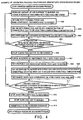
- Fig. 1 is a schematic view showing the configuration and the gas supply system of a hydrogen generator according to Embodiment 1 of the present invention.
- a hydrogen generator 10 mainly comprises a controller 9, a reformer 21 for supplying a hydrogen-rich reformed gas, a material feed system 22 for feeding a feed gas to the reformer 21 in addition to adjusting a feed gas flow rate, a water supply system 23 for supplying water to the reformer 21 in addition to adjusting a water flow rate, and an air supply system 24 for supplying air to a burner 2 in addition to adjusting an air flow rate.
- the reformer 21 is furnished with a reforming portion 1 for steam-reforming a feed gas and steam by a reforming catalyst body 74 (see Fig. 3 ), a burner 2 for supplying heat for a reforming reaction to the reforming catalyst body 74, a reforming temperature measuring portion 4 for detecting the temperature of the reforming catalyst body 74 of the reforming portion 1, a shifter 6 for reducing, by a shift catalyst body (not shown), the concentration of CO in the gas that is sent out from the reforming portion 1, and a carbon monoxide oxidizing portion 7 for further reducing, by a carbon monoxide oxidizing catalyst body (not shown), the concentration of CO in the gas that is sent out from the shifter 6.
- the reforming catalyst body 74 used is that prepared in a pellet state by making a Ru-based catalyst carry alumina
- the shift catalyst body used is that made into a honeycomb substrate by making a Ce oxide carry platinum
- the carbon monoxide oxidizing catalyst body used is that made into a honeycomb substrate by making alumina carry platinum.
- the feed gas include, but are not limited to, hydrocarbon-based gases such as natural gas or LPG, alcohols such as methanol, and naphtha components.
- a natural gas containing methane gas as its main component is used; therefore, the material feed system 22 is provided with a desulfurization portion 5 that incorporates a zeolite adsorbent for removing a sulfur component contained in the natural gas.
- the water supplied from the water supply system 23 is ion-exchanged and then supplied to the reforming portion 1.
- An evaporation system (not shown) for letting water evaporate may be installed either inside the reforming portion 1 or outside the reforming portion 1.
- an air supply system 24 for supplying air is coupled to the burner 2.
- the air supply system 24 is provided with, for example, a sirocco fan 3.
- a reforming temperature measuring portion 4 and a feed gas flow rate meter 12 there are provided a feed gas flow rate control portion (not shown) of the material feed system 22, first and second feed gas supply valves 31 and 34 for supplying a feed gas, which are disposed so as to sandwich the desulfurization portion 5, a water flow rate adjusting portion (not shown) of the water supply system 23, a water supply valve 33 for supplying water, an air flow rate-adjusting portion (not shown) of the air supply system 24, first and second open/close valves 36 and 37, and so forth.
- a hydrogen-rich reformed gas produced by such a hydrogen generator 10 is utilized for, for example, a fuel cell system that uses hydrogen as its fuel.
- the controller 9 opens the first and second feed gas supply valves 31 and 34, disposed sandwiching the desulfurization portion 5 in the midstream of the feed gas supply path 30 of the material feed system 22, to supply a natural gas to the reforming portion .1 of the reformer 21.
- an odorant component (sulfur component) in the natural gas being a poisonous component for the catalyst of the hydrogen generator 10 is removed by a zeolite adsorbent incorporated in the desulfurization portion 5 that is upstream of the reformer 21 so that molecules of the sulfur component in the feed gas are reduced to 1/100,000,000 of the total mole number of feed gas molecules.
- the first feed gas supply valve 31 is an open/close valve for controlling whether or not to supply the feed gas
- the second feed gas supply valve 34 is an open/close valve for inhibiting the desulfurization portion 5 from being left open when stopping the material feed system 22.
- the controller 9 opens the water supply valve 33 disposed in midstream of the water supply path 32 to supply the ion-exchanged water to the reforming portion 1. Note that the balance of amounts between the natural gas and the water supplied is adjusted so that the supplied water amount is about 3 times the number of elemental carbon contained in the natural gas.
- a portion of the feed gas is sent to the burner 2 through the feed gas branching passage 35 and burnt inside the burner 2; thereby, the reforming catalyst body 74 (see Fig. 3 ) receives a necessary amount of generated heat for the reforming reaction, and a hydrogen-rich reformed gas is generated in the reforming portion 1 from the feed gas and the water of the reforming portion 1 in a state in which the temperature of the reforming catalyst body 74 is kept at about 700°C.
- the controller 9 monitors the temperature detected by the reforming temperature measuring portion 4 and keeps track of the status of the reforming reaction. Based on the detected temperature, it controls the feed gas flow rate adjusting portion of the material feed system 22 and the first feed gas supply valve 31 as well as the water flow rate adjusting portion of the water supply system 23 and the water supply valve 33 so that predetermined amounts of feed gas and water can be supplied.
- the reformed gas generated by the reforming portion 1 contains about 10% (on a dry gas basis) of a carbon monoxide gas and a carbon dioxide gas, and therefore, when it is used for a fuel cell, it is necessary to reduce the carbon monoxide gas concentration to a level that does not poison the anode catalyst of the fuel cell. For this purpose, after flowing through the shifter 6, this reformed gas is sent to the carbon monoxide oxidizing portion 7 along with a trace amount of oxygen gas.
- the temperature of the shift catalyst body is kept at about 250°C to cause the steam and the carbon monoxide gas to form hydrogen and carbon dioxide gas by a shift reaction, and thereby, the carbon monoxide gas concentration of the reformed gas after the shift reaction is reduced to about 0.5% and the carbon dioxide gas concentration to 19.5% (on a dry gas basis).
- the temperature of the carbon monoxide oxidizing catalyst body is kept at about 120°C to 160°C to cause the carbon monoxide gas in the reformed gas to react with an oxygen gas with this catalyst body, and thus, the concentration of carbon monoxide is reduced to 10 ppm. In this way, the reformed gas inside the reformer 21 is made into a condition in which impurities are removed therefrom so that it can withstand the use for a fuel cell or the like.
- the following describes an operation of a gas supply system in which an interior of the reformer 21 is purged with a feed gas after shifting from a normal operation to an operation shutdown procedure.
- the purging gas supplied to the reformer 21 is changed when a predetermined temperature is reached in the reforming catalyst body 74 of the reforming portion 1, and therefore, how the gas control is performed and why such a control is performed are described for each of the respective cases where the temperature is above and below the predetermined temperature.
- the predetermined temperature indicates a lower limit temperature at which carbon deposition can occur by thermal decomposing a feed gas, but regardless of the carbon deposition temperature, the predetermined temperature does not become lower than the temperature at which steam condensation starts to occur (100°C or lower).
- the predetermined temperature denotes a higher one of the lower limit temperature at which carbon deposition can occur by thermal decomposition of a feed gas and the temperature at which steam condensation starts to occur.
- the temperature range of carbon deposition of natural gas by thermal decomposition is about 400°C or higher, while the temperatures range of steam condensation is about 100°C or lower. Accordingly, in the case of using a natural gas, the predetermined temperature is about 400°C.
- the controller 9 detects the temperature of the reforming catalyst body 74 with the reforming temperature measuring portion 4, which is installed in the reforming portion 1 shown in Fig. 1 , and constantly monitors whether or not the detected temperature has reached the predetermined temperature.
- the temperature of the reforming catalyst body 74 of the reforming portion 1 has been elevated to about 700°C.
- Both the feed gas and water are sent into the reforming portion 1 during a period in which the reforming catalyst body 74 of the reforming portion 1 is cooled to the predetermined temperature (400°C in the case of natural gas, which is the lower limit temperature at which carbon deposition occurs by thermal decomposition) from the elevated temperature (in other words, during a period in which the temperature of the reforming catalyst body 74 is at a predetermined temperature or higher) by later-described heat exchange between the reforming catalyst body 74 and the burner 2.
- both the feed gas and steam are supplied to the reforming catalyst body 74, that is, in the case where the reforming catalyst body 74 is at the above-noted predetermined temperature or higher, it is necessary to make the amount of the feed gas supplied greater than the amount of dissolved oxygen contained in water on a molar basis and to keep a ratio S/C of carbon in the feed gas with respect to steam (steam-carbon ratio) at 2 or greater for the following reason.
- Water contains a trace amount of oxygen gas dissolved therein, and even the trace amount of oxygen gas can promote catalyst deterioration by oxidation at a higher temperature than the temperature at which the reforming catalyst body 74 can be readily oxidized (300°C or higher with Ru-based catalyst). Nevertheless, dissolved oxygen contained in water tends to react with a feed gas more readily rather than with the reforming catalyst body 74 (Ru-based catalyst); therefore, if the feed gas is supplied at an amount greater than the amount of dissolved oxygen contained in water (on a molar basis), the dissolved oxygen is completely used up by the reaction with the feed gas. Thus, the cause of oxidation deterioration of the reforming catalyst body 74 can be eliminated.
- a temperature decrease of the reforming catalyst body 74 of the reforming portion 1 proceeds, and at the time when the temperature detected by the reforming temperature measuring portion 4 reaches the above-noted predetermined temperature, the controller 9 performs a control to close the water supply valve 33 so as to stop supplying water, followed by the purging of the reformer 21 only with the feed gas.
- the steam inside the reformer 21 can be removed in advance with a feed gas, eliminating steam condensation inside the reformer 21 fundamentally. If the steam could not be completely eliminated with a feed gas, steam condensation would occur inside the reformer 21 at the time when the temperature of the reformer 21 becomes lower than the steam condensation temperature; thus, not only would the condensed water inhibit quick heating of the reformer 21 in restarting the reformer 21, prolonging the start-up time of the reformer 21 unduly but also might deteriorate the characteristics of the reforming catalyst body 74, the shift catalyst body, and the carbon monoxide oxidizing catalyst body inside the reformer 21.
- the amount of the feed gas to be supplied needs to be at least equal to or greater than the internal volume of the reformer 21 (1 or more times the internal volume of the reformer), desirably two or more times the internal volume of the reformer 21.
- the internal volume of the reformer 21 is 1 L
- the feed gas is made to flow in the reformer 21 in an amount of 2 L (two times of the internal volume) so that the atmosphere inside the reformer 21 can be purged completely.
- the total flow rate of the feed gas the flow rate of the feed gas may be 1 L/minute and the purging time may be 2 minutes, or the flow rate of the feed gas may be 2 L/minute and the purging time may be 1 minute.
- the controller 9 monitors the feed gas flow rate meter 12 disposed in the midstream of the feed gas supply path 30 between the first feed gas supply valve 31 and the reforming portion 1, and the total amount of the supplied feed gas is controlled at a desired amount based on the detected signal from the flow rate meter 12.
- the interior of the reformer 21 can be appropriately purged from the time immediately after the shutdown of the reformer 21 without deteriorating catalysts inside the reformer 21 by oxidation.
- an outlet port 40 of the reformer 21 (more specifically, an outlet port 40 provided in the carbon monoxide oxidizing portion) is coupled to the existing burner 2 so that a post-purging feed gas (which may be a hydrogen-rich reformed gas originating from a reforming reaction, depending on the temperature condition of the reforming catalyst body 74, but hereafter, they are collectively referred to as a "feed gas" in the description of the purge gas post-processing system) that has completed the purging of the interior of the reformer 21 can be returned through the return gas passage 41 to the burner 2; in addition, at the time when the interior of the reformer 21 is purged with the feed gas and steam, the number of revolutions of the sirocco fan 3 of the air supply system 24 is increased to be greater than that during a normal operation to send air into the burner 2 in excess.
- a post-purging feed gas which may be a hydrogen-rich reformed gas originating from a reforming reaction, depending on the temperature condition of the reforming catalyst body 74, but here
- the post-purging feed gas and the air are mixed within the burner 2, and the concentration of combustible gas in the mixed gas is diluted to be less than a combustible concentration.
- a flame of the burner 2 is put out, and the mixed gas is discharged to atmosphere.
- a water removing system is disposed at an appropriate position in the return gas passage 41, and thereby, water content (minute water drops or steam) contained in the purge gas that has purged the interior of the reformer 21 and is introduced into the burner 2, is appropriately removed. Even if the water content is not completely removed by the water removing system and flows into the burner 2 accompanying the purge gas, such water content is effectively discharged outside by sending air into the burner 2 in excess with the sirocco fan 3, which is desirable.
- the first advantageous effect is as follows.
- the burner 2 is originally intended to heat the reforming catalyst body 74 and therefore is designed to efficiently perform heat exchange therebetween. Consequently, making use of this function, the air introduced from the air supply system 24 can have the function of promoting the cooling of the reforming catalyst body 74 in addition to the function of diluting a combustible gas.
- the introduction of air into the burner 2 that can effectively perform heat exchange with the reforming catalyst body 74 in an amount greater than the amount of the air supplied during a normal operation has an advantageous effect of, not heating the reforming catalyst body 74, but quickly cooling the temperature of the reforming catalyst body 74 to a temperature at which oxidation deterioration or carbon deposition of the feed gas does not occur.
- Fig. 2 changes over time of the degree of cooling of the reforming catalyst body 74 after stopping the heating by the burner 2 for maintaining the reforming temperature of the reforming catalyst body 74 are compared under various burner gas supply conditions, the conditions of the return of post-purging feed gas and the introduction of air to the burner.
- Pattern A in Fig. 2 represents an example of the decrease in the temperature of the reforming catalyst body in the case where neither the return of a feed gas to the burner 21 nor the introduction of air by the air supply system 24 to the burner 21 is performed, no particular action is taken, and the burner 2 is left as it is.
- Pattern B represents an example of the decrease in the temperature of the reforming catalyst body in the case where: the reformer 21 is purged with a feed gas and steam until the temperature of the reforming catalyst body 74 reaches 400°C and with only the feed gas after the temperature has reached 400°C; and the post-purging purge gas is returned through the return gas passage 41 to the burner 21 but the introduction of air from the air supply system 24 is not performed.
- Pattern C represents an example of the decrease in the temperature of the reforming catalyst body in the case where: the reformer 21 is purged with a feed gas and steam until the temperature of the reforming catalyst body 74 reaches 400°C and with only the feed gas after the temperature reaches 400°C; and both the return of the post-purging purge gas through the return gas passage 41 to the burner 21 and the introduction of air from the air supply system 24 to burner 2 are performed.
- Pattern c shows that the temperature of the reforming catalyst body 74 dropped over time most quickly. This proves the advantageous effect according to the configuration of Embodiment 1 that cooling can be promoted utilizing the heat exchange between the burner 2 and the reforming catalyst body 74. It should be noted that Pattern b shows a superior cooling effect on the reforming catalyst body 74 than that of Pattern a . This indicates that it is possible to promote cooling of the reforming catalyst body 74 through the heat exchange between the reforming catalyst body 74 and the burner 2 even with only the return of the purge gas for the reformer 21.
- the second advantageous effect is as follows.
- the flame of the burner 2 is burning to heat the reforming catalyst body 74 of the reforming portion 1, the flame can be put out (the combustion of combustible gas can be stopped) by increasing the output power (number of revolutions) of the sirocco fan 3 of the air supply system 24 according to the supply of a combustible purge gas to the reformer 21 so that a large amount of air is introduced at a time and the concentration of the combustible gas is diluted to be less than a predetermined combustible concentration.
- the combustible gas is hydrogen gas
- the combustible dilution limit concentration is 4%
- the combustible condensation limit concentration is 75%. Accordingly, in order to dilute the concentration of hydrogen to be less than the combustible concentration, it is necessary to increase the number of revolutions of the sirocco fan 3 to increase the supplied air amount from the fan to the burner 2 so that the hydrogen concentration becomes less than 4%.
- the combustible gas is methane gas
- the combustible dilution limit concentration is 5% while the combustible condensation limit concentration is 15%. Accordingly, in order to dilute the concentration of methane gas to be less than the combustible concentration, it is necessary to increase the number of revolutions of the sirocco fan 3 to increase the supplied air amount from the fan to the burner 2 so that the methane gas concentration becomes less than 5%.
- the amount of the supplied feed gas that is returned to the burner 2 and the amount of the supplied air introduced to the burner 2 are both controlled by the controller 9 so that the combustible gas in the feed gas is reliably diluted to have a concentration less than the combustible concentration, and thus, the flame of the burner 2 can be put out.
- This makes it possible to reliably shift, in the burner 2, a heated state for maintaining the reforming temperature of the reforming catalyst body 74 to a diluted and diffused state of the feed gas and a cooled state of the reforming catalyst body 74.
- Fig. 3 shows a cross section of: the burner 2, which mainly comprises a combustion cylinder 68, a combustible gas pipe 64, and an air buffer 69; and a peripheral structure 60 of the reforming catalyst body 74, which mainly comprises the reforming catalyst body 74, an enclosure case 77 for enclosing the reforming catalyst body 74, and an outer wall 78.
- feed gas or the reformed gas (hereafter collectively referred to as "feed gas” in the description referring to Fig. 3 ), the direction of which is turned about 90° within the tubular-shaped combustible gas pipe 64, is guided toward the direction of the combustion cylinder 68. Subsequently, the stream of the feed gas is blocked at a time by a gas pipe lid 65 that seals the downstream end of the combustible gas pipe 64 and is split into a plurality of streams by feed gas blow holes 66 provided on the side face of the combustible gas pipe 64 in the vicinity of the gas pipe lid 65, and the feed gas is discharged in an inward direction of the combustion cylinder 68.
- combustion air supplied from an air inlet port 63 which is connected to the sirocco fan 3 of the air supply system 24 (see Fig. 1 ), is introduced to an air buffer 69 provided around the tubular-shaped combustible gas pipe 64 in a circular shape.
- the air stream of the air buffer 69 is split into a plurality of streams by air blow holes 70 formed in the inclined surface of the recessed portion in a reversed corn shape and discharged in an inward direction of the combustion cylinder 68.
- the mixed gas containing the feed gas and ,the air thus introduced in an inward direction of the combustion cylinder 68 is burnt in a flame region 67 formed in the recessed portion of the burner 2 with the amounts thereof being controlled by the controller 9 so that the concentration of combustible gas in the feed gas falls within the combustible concentration range (for example, in the case of hydrogen gas, the concentration is kept within the range of from 4% to 75%).
- a high-temperature combustion gas generated by the combustion is passed through the interior of the burner 2, as indicated by dotted lines in Fig. 3 .
- the combustion gas goes up within the combustion cylinder 68, and the rise is blocked at a combustion cylinder lid 71 provided at the upper end of the combustion cylinder 68.
- the stream of the combustion gas is split into a plurality of streams by combustion gas blow holes 73 formed in a side wall 72 of the combustion cylinder 68 near the combustion cylinder lid 71, and discharged outside the combustion cylinder 68.
- the combustion gas discharged outside the combustion cylinder 68 is passed through a space between a first wall 75 of the reforming catalyst body 74's enclosure case 77 for enclosing the reforming catalyst body 74 and the side wall 72 of the combustion cylinder 68, and is lowered in the opposite direction to the above-mentioned rising direction of the combustion gas. Thereafter, the direction of the streams is changed about 180° in the vicinity of the flame region 67. Then, the combustion gas is guided upward through the space between the second wall 76 of the enclosure case 77 and an outer wall 78, and is discharged as an exhaust gas into atmosphere.
- the high-temperature combustion gas makes contact with the reforming catalyst body 74 through the first and second walls 75 and 76 of the enclosure case 77 all the time.
- the reforming catalyst body 74 can receive the heat amount of the combustion gas efficiently, elevating its temperature to the catalyst reaction temperature (about 700°C) smoothly.
- peripheral structure 60 of the reforming catalyst body 74 is designed so that heat exchange can easily take place between the reforming catalyst body 74 and the high-temperature gas that flows so as to come into contact with the enclosure case 77.
- the heat accumulated in the reforming catalyst body 74 is removed therefrom by the mixed gas containing the feed gas and air in the following manner. It should be noted that the method of introducing the feed gas and air to the burner 2 is the same as that used when the burner 2 is used as a heater, and therefore, the description thereof is omitted.
- the amounts of the feed gas and air supplied are controlled by the controller 9 so that the concentration of the combustible gas becomes less than the combustible concentration (for example, so that the gas concentration becomes less than 4% in the case of hydrogen gas) in the flame region 67.
- the output power of the sirocco fan 3 is increased to be greater than that in the case of burning the combustible gas within the burner 2 so as to introduce air to the burner 2 in excess and to increase the amount of the air supplied to the flame region 67 of the burner 2; thus, it becomes possible to dilute the concentration of the combustible gas in the flame region 67 of the burner 2 and to put out the flame (stop the combustion of the combustible gas).
- the burner 2 can be smoothly shifted from a combustible gas burning state to a combustible-gas burning shutoff state.
- the mixed gas containing the feed gas and air introduced into the combustion cylinder 68 flows inside the burner 2 in a similar manner to the combustion gas, as indicated by dotted lines in Fig. 3 .
- the mixed gas is not burnt inside the combustion cylinder 68 but goes up in the interior of the combustion cylinder 68, and the rise is blocked at the combustion cylinder lid 71 provided at the upper end of the combustion cylinder 68.
- the stream of the mixed gas is split into a plurality of streams by the combustion gas blow holes 73 formed in the side wall 72 of the combustion cylinder 68 near the combustion cylinder lid 71, and is discharged outside the combustion cylinder 68.
- the mixed gas discharged out of the combustion cylinder 68 is lowered in the opposite direction to the above-mentioned gas rising direction through the space between the first wall 75 of the reforming catalyst body 74's enclosure case 77 that encloses the reforming catalyst body 74 and the side wall 72 of the combustion cylinder 68. Thereafter, the direction of the mixed gas stream is changed about 180° in the vicinity of the lower end of the combustion cylinder 68, then the mixed gas is guided upward through the space between the second wall 76 of the enclosure case 77 and the outer wall 78, passing through the same route as the discharge route of the combustion gas (the combustion gas route indicated by dotted lines in the figure), and is discharged to atmosphere.
- the mixed gas While going up and down in substantially vertical directions, the mixed gas makes contact with the reforming catalyst body 74, the temperature of which has been elevated to about 700°C for maintaining the reforming temperature, through the first and second walls 75 and 76 of the enclosure case, and performs heat exchange therewith. As a consequence, the mixed gas removes heat from the reforming catalyst body 74 efficiently, making it possible to smoothly reduce the temperature of the reforming catalyst body 74.
- the third advantageous effect is as follows. As described with Fig. 3 , the existing burner 2 and the existing air supply system can be effectively utilized in diluting the concentration of the combustible gas in the purge gas to be less than the combustible concentration in the flame region 67 of the burner 2 and discharging it to atmosphere, and therefore, an increase in manufacturing cost arising from upgrading equipment or the like is prevented.
- the amount of the feed gas supplied from the material feed system 22 to the reformer 21 (the amount corresponding to the purge gas amount) and the amount of the air supplied from the air supply system 24 (sirocco fan 3) to the burner 2 are appropriately controlled by the controller 9.
- the concentration of the combustible gas in the mixed gas containing the purge gas (feed gas or reformed gas) and air can be diluted to be less than the combustible concentration within the burner 2 and discharged to atmosphere.
- a flame is put out by diluting the concentration of the combustible gas to be less than the combustible concentration, and the temperature of the reforming catalyst body 74 can be quickly lowered by the mixed gas to a temperature such that deterioration by oxidation or carbon deposition of the feed gas does not occur.
- Fig. 4 which shows steps S401 to S414, is a flowchart illustrating an example of the process operation from stopping the heating by the burner 2 (putting out a flame of the burner 2) for maintaining the reforming temperature of the reforming catalyst body 74 to hermetical closing of the hydrogen generator 10.
- Fig. 4 shows the content of the processes executed by the controller 9 when shutting down the hydrogen generator 10.
- the controller 9 raises the output power of the sirocco fan 3 to increase the amount of the air supplied to the burner 2.
- a feed gas is supplied from the material feed system 22 through the desulfurizer 5 to the interior of the reformer 21 and steam is also supplied from the water supply system 23 to the interior of the reformer 21; with these gases, the interior of the reformer 21 is purged (step S401).
- the post-purging purge gas (containing hydrogen and steam-containing reformed gas as its main components) is discharged from the outlet port 40 of the reformer 21 and is returned to the burner 2 (step S402). Then, the purge gas that has been returned to the burner 2 and the air supplied in excess are mixed together and the concentration of combustible gas is diluted to be less than the combustible concentration (step S403).
- step S404 the mixed gas containing the diluted purge gas and air is discharged to atmosphere.
- air is constantly kept supplied from the sirocco fan 3 of the air supply system 24 to the burner 2.
- the controller 9 detects the temperature of the reforming catalyst body 74 with the reforming temperature measuring portion 4 and determines whether or not the detected temperature is at a predetermined temperature or higher (step S405).
- the predetermined temperature denotes a higher one of the lower limit temperature at which carbon deposition occurs by thermally decomposing the feed gas and the temperature at which steam condensation starts to occur. If the temperature detected by the reforming temperature measuring portion 4 is at the predetermined temperature or higher (if yes in step S405), the contiguous purging operation of steps S401 to S404 is continued. At the time when the temperature detected by the reforming temperature measuring portion 4 has become lower than the predetermined temperature (if no in step S405), the process proceeds to the next step, and the controller 9 controls the water supply system 23 to stop supplying water (step S406).
- the controller 9 allows the purging of the interior of the reformer 21 only with the feed gas (step S407).
- the post-purging purge gas (main component: feed gas) is returned to the burner 2 (step S408), and the purge gas is mixed with excessive air that is sent from the sirocco fan 3 to the burner 2 to dilute the concentration of the combustible gas in the mixed gas to be less than the combustible concentration (step S409).
- the mixed gas containing the diluted purge gas and air is discharged to atmosphere (step S410).
- air is constantly supplied from the sirocco fan 3 of the air supply system 24 to the burner 2.
- the controller 9 monitors the total amount of the supplied feed gas with the feed gas flow rate meter 12 (see Fig. 1 ) and determines whether or not the feed gas has been supplied to the reformer 21 in an amount equal to or greater than a predetermined amount (step S411).
- the set value of the predetermined amount should be at least equal to or greater than the internal volume of the reformer 21, desirably 2-3 or more times the internal volume thereof.
- the contiguous purging operation from step S407 to step S410 is continued.
- the controller 9 controls the material feed system 22 to stop supplying the feed gas to the reformer 21 (step S412).
- the controller 9 stops the operation of the sirocco fan 3 to halt the air supply to the burner 2 (step S413). Then, the first and second feed gas supply valves 31, 34, the water supply valve 33, and the first and second open/close valves 36, 37 are closed, and the hydrogen generator 10 is hermetically closed (step S409) to end the operation shutdown procedure of the hydrogen generator 10.
- the interior of the reformer 21 can be purged with a feed gas, and the post-purging feed gas and/or reformed gas can be efficiently processed by diluting the gas(es) within the burner 2; moreover, cooling of the burner 2 can be performed quickly.
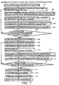
- Fig. 5 is a schematic view showing the configuration and the gas supply system of a fuel cell system according to Embodiment 2 of the present invention
- Embodiment 2 The configurations of a reformer 21, a material feed system 22, a water supply system 23, and an air supply system 24 in Embodiment 2 are identical to those in Embodiment 1 and therefore not further elaborated upon.
- a primary difference in the configuration of Embodiment 2 is that the outlet port 40 provided on the carbon monoxide oxidizing portion 7 of the reformer 21 is coupled to an anode 8a of a polymer electrolyte fuel cell 8 via a reformed gas supply path 42 and further the anode 8a of the fuel cell 8 is coupled to the burner 2 via the reformed gas return path 43, so that a fuel cell system 50 is constructed with the hydrogen generator 10 and the fuel cell 8.
- a reformed gas containing hydrogen as its main component is supplied to the anode 8a of the fuel cell 8.
- the reformed gas that has not been consumed by power generation is returned from the fuel cell 8 to the burner 2 through the reformed gas return path 43 and a third open/close valve 38 disposed in the return path 43, and is burnt inside the burner 2 to maintain the temperature of the reforming catalyst body 74.
- a cathode 8c of the fuel cell 8 is supplied with an oxidizing gas, although the description of the supply route of the oxidizing gas will be omitted.
- a feed gas and/or a reformed gas is/are appropriately returned upon the start-up of or during the operation of the reformer 21 to the burner 2 so as to be burnt within the burner 2 in order to maintain the elevated temperature of the reforming catalyst body 74.
- the third open/close valve 38 is also controlled by the controller 9.
- the purge gas (main component: hydrogen-rich reformed gas) is sent into the anode 8a of the fuel cell 8 through the reformed gas supply path 42, causing the anode 8a to consume hydrogen and continue power generation of the fuel cell 8, until the temperature of the reforming catalyst body 74 decreases to a predetermined temperature.
- the predetermined temperature denotes a higher one of the lower limit temperature at which carbon deposition occurs by thermally decomposing the feed gas or the temperature at which steam condensation occurs (100°C), which has the same meaning as that in Embodiment 1.
- Fig. 6 illustrates the relationship between temperatures of the reforming catalyst body and conversion ratios with S/C ratios (steam/carbon ratios) being a parameter. Fig. 6 shows that the conversion ratio (%) of hydrogen with the reforming catalyst body 74 with respect to feed gas tends to decrease as the temperature of the reforming catalyst body 74 is reduced.
- the temperature of the reforming catalyst body gradually decreases over time after the heating by the burner 2 for maintaining the reforming temperature of the reforming catalyst body 74 has been stopped (see Fig. 2 ), and therefore, due to the effect of this, the conversion ratio also gradually decreases.
- the controller .9 the ratio obtained by dividing the total amount of hydrogen consumed by a hydrogen reaction inside the fuel cell 8 by the total amount of hydrogen contained in the reformed gas passing through the reformed gas supply path 42 (hydrogen consumption rate) according to the decrease of the temperature of the reforming catalyst. That is, because the proportion of hydrogen in the purge gas reduces according to the gradual decrease of the hydrogen conversion ratio originating from the .temperature decrease of the reforming catalyst body 74, the hydrogen consumption rate increases consequently in order to keep a desired amount of generated power.
- the purge gas (reformed gas) discharged from the fuel cell 8 that has not contributed to the power generation is directly returned into the burner 2 through the reformed gas return path 43, is diluted in the burner 2, and is thrown away; for this reason, it is desirable to increase the hydrogen consumption rate to be greater than that in the heating by the burner 2 for maintaining the reforming temperature of the reforming catalyst body 74 so that it can be used for power generation in the fuel cell 8 as much as possible.
- the first and second feed gas supply valves 31, 34 disposed on the feed gas supply path 30, the water supply valve 33 disposed on the water supply path 32, the first open/close valve 36 disposed on the return gas passage 41, the second open/close valve 37 disposed on the reformed gas supply path 42, and the third open/close valve 38 disposed on the reformed gas return path 43 are closed and the fuel cell system 50 is hermetically closed, to contain the feed gas inside the reformer 21 and the fuel cell 8. This makes it possible to prevent air from being mixed in the internal atmosphere of the reformer 21 and the fuel cell 8, and to inhibit the combustible feed gas from becoming the combustible concentration range.
- Fig. 7 which shows steps S701 to S716, is a flowchart illustrating an example of the process operations from stopping of heating by the burner 2 (putting out a flame of the burner 2) for maintaining the reforming temperature of the reforming catalyst body 74 to hermetical closing of the fuel cell system 50.
- Fig. 7 shows the content of the processes executed by the controller 9 when shutting down the fuel cell system 50.
- the controller 9 raises the output power of the sirocco fan 3 to increase the amount of the air supplied to the burner 2, for the purpose of stopping the heating of the reforming catalyst body 74. Meanwhile, a feed gas is supplied from the material feed system 22 through the desulfurizer 5 to the interior of the reformer 21, and steam is also supplied from the water supply system 23 to the interior of the reformer 21; with these gases, the interior of the reformer 21 is purged (step S701).
- the post-purging purge gas (containing hydrogen and steam-containing reformed gas as its main components) is discharged from the outlet port 40 of the reformer 21 and is supplied to the fuel cell 8, and power generation is continued in the fuel cell 8 so that hydrogen in the purge gas is consumed (step S702).
- the remaining purge gas that has not been consumed in the fuel cell 8 is returned to the burner 2 (step S703).
- the purge gas returned to the burner 2 is mixed with excess air to dilute and the concentration of a combustible gas to be less than the combustible concentration (step S704).
- the operation of quickly reducing the temperature of the reforming catalyst body 74 with a mixed gas at the same time of diluting the purge gas is the same as that described in Embodiment 1.
- the mixed gas containing the diluted purge gas and air is discharged to atmosphere (step S705).
- air is constantly supplied from the sirocco fan 3 of the air supply system 24 to the burner 2.
- the controller 9 detects the temperature of the reforming catalyst body 74 with the reforming temperature measuring portion 4 and determines whether or not the detected temperature is at a predetermined temperature or higher (step S706).
- the predetermined temperature denotes a higher one of the lower limit temperature at which carbon deposition occurs by thermally decomposing the feed gas and the temperature at which steam condensation starts to occur.
- step S706 If the temperature detected by the reforming temperature measuring portion 4 is at the predetermined temperature or higher (if yes in step S706), the contiguous purging operation of steps S701 to S705 is continued. At the time when the temperature detected by the reforming temperature measuring portion 4 has become lower than the predetermined temperature (if no in step S706), the process proceeds to the next step, and the controller 9 controls the water supply system 23 to stop supplying water (step S707).
- the controller 9 allows the purging of the interior of the reformer 21 and the purging the interior of the fuel cell 8 only with the feed gas (steps S708 and S709).
- the post-purging purge gas (main component: feed gas) is returned to the burner 2 (step S710), and the purge gas is mixed with excessive air sent from the sirocco fan 3 to the burner 2 to dilute the concentration of a combustible gas in the mixed gas to be less than the combustible concentration (step S711).
- the mixed gas containing the diluted purge gas and air is discharged to atmosphere (step S712).
- air is constantly supplied from the sirocco fan 3 of the air supply system 24 to the burner 2.
- the controller 9 monitors the total amount of the supplied feed gas with the feed gas flow rate meter 12 (see Fig. 5 ) and determines whether or not only the feed gas has been supplied to the reformer 21 in an equal to or amount greater than a predetermined amount (step S713).
- the set value of the predetermined amount should be at least equal to or greater than the internal volume of the reformer 21, desirably 2-3 or more times the internal volume.
- the contiguous purging operation from step S708 to step S712 is continued.
- the controller 9 controls the material feed system 22 to stop supplying the feed gas to the reformer 21 (step S714).
- the controller 9 halts the operation of the sirocco fan 3 to stop the air supply to the burner 2 (step S715). Then, the first and second feed gas supply valves 31, 34, the water supply valve 33, and the first, second, and third open/close valves 36, 37, 38 are closed, and the fuel cell system 50 is hermetically closed (step S716) to end the operation shutdown procedure of the fuel cell system 50.
- the interior of the reformer 21 can be purged with a feed gas, and the post-purging feed gas and/or reformed gas can be efficiently processed by diluting the gas (gases) within the burner 2; moreover, cooling of the burner 2 can be performed quickly. Furthermore, even after the heating by the burner 2 for maintaining the reforming temperature of the reforming catalyst body is stopped, a reformed gas is supplied to the fuel cell 8 to continue power generation with the anode 8a of the fuel cell 8 so that energy can be obtained; the amount of purge gas that is to be disposed of can be minimized and the amount of air used for diluting the purge gas can also be saved, leading to reduction in energy loss.
Landscapes
- Chemical & Material Sciences (AREA)
- Chemical Kinetics & Catalysis (AREA)
- Engineering & Computer Science (AREA)
- Life Sciences & Earth Sciences (AREA)
- Sustainable Development (AREA)
- General Chemical & Material Sciences (AREA)
- Sustainable Energy (AREA)
- Electrochemistry (AREA)
- Manufacturing & Machinery (AREA)
- Organic Chemistry (AREA)
- Combustion & Propulsion (AREA)
- Health & Medical Sciences (AREA)
- General Health & Medical Sciences (AREA)
- Inorganic Chemistry (AREA)
- Fuel Cell (AREA)
- Hydrogen, Water And Hydrids (AREA)
- Gas Burners (AREA)
Description
- The present invention relates to a hydrogen generator and a method of shutting down its operation as well as a fuel cell system, and more particularly to a hydrogen generator in which an interior of a reformer can be purged so that a combustible gas emitted to its outside can be appropriately processed and a method of shutting down its operation as well as a fuel cell system.
- There are known reformers (reformer systems) that generate a reformed gas containing hydrogen as its main component by a steam reforming reaction with steam and an organic material such as natural gas or naphtha.
- Among reforming catalyst bodies that contribute to this steam reforming reaction is one in which a carrier such as alumina carries a Ni-based or a Ru-based catalyst. The performance of the reforming catalyst body, however, greatly depends on the atmosphere of the surrounding environment; for example, the Ni-based catalyst can exhibit its expected performance in a reduced state but its catalytic activity deteriorates in an oxidized state. Likewise, the Ru-based catalyst tends to volatilize easily and therefore shows degraded catalytic activity in an oxidized state at high temperature.
- Particularly during a shutdown period of the reformer, there is a possibility of air (oxygen) intruding therein from the outside of the equipment due to the depressurizing effect originating from the temperature decrease of a high-temperature remaining gas in the reformer, and there is an increasing concern over the deterioration of the reforming catalyst body by oxidation. Therefore, it is necessary to take a measure to inhibit oxidation of catalysts during a shutdown period of the reformer. For this purpose, the following method has been adopted; after ceasing maintaining the temperature of the reforming catalyst body at a high reforming temperature (at 700°C, for example), purging is performed in such a manner that an inert gas such as nitrogen is introduced into the interior of the reformer and the interior of the reformer is filled with nitrogen in order to replace the high-temperature remaining gas in the interior of the reformer; thereafter, the upstream and downstream of the reformer are closed by sealing valves to inhibit deterioration of the reforming catalyst body.
- Another method in which a hydrogen generator is purged with a feed gas for the hydrogen generator itself in place of nitrogen has been proposed as remedies for the increased cost and complexity associated with obtaining nitrogen. (See, for example,
Japanese Unexamined Patent Publication 2000-95504 - Although the foregoing publication does not mention post-processing of a combustible purge gas that is forced out by purging the reformer, a post-processing method normally assumed for effectively utilizing existing equipment is such that a purge gas is returned to a burner for heating the reforming catalyst body of the reformer and then combustion-treated with the burner.
- When the interior of the reformer is purged with a feed gas, it is important to reduce the temperature of the reforming catalyst body as quickly as possible so as not to thermally decompose the feed gas and to complete the purging operation for the reformer within a minimum time, from the viewpoint of saving the energy required for the purging. Nevertheless, the above-described combustion of the purge gas in the burner functions to reduce the rate of the temperature decrease of the reforming catalyst body and thereby delays the purging of the reformer, leading to an increase in energy loss in the hydrogen generator. Moreover, if a purge gas that is useful as a power generation gas is burnt in the burner when purging the reformer, the amount of heat that is to be produced by this combustion cannot be utilized effectively, and effective utilization of energy cannot be attained.
-
EP 1 316 529 A1 -
US-A-4,965,143 discloses a method for shutting down a reformer for reforming a fuel, where the amount of heat supplied to the heater is reduced while continuing to supply unreformed fuel to the catalyst bed for cooling the catalyst bed through endothermic reaction. -
WO 03/078311 A1 - The present invention has been accomplished in view of the foregoing circumstances, and it is an object of the present invention to provide a hydrogen generator in which, when the interior of the reformer is purged with a feed gas, a purge gas containing the feed gas or a reformed gas (combustible gas) can be post-processed efficiently by the burner Of the reformer: it is also an object of the invention to provide a method of shutting down an operation of a hydrogen generator that is capable of stopping combustible gas combustion of the burner and efficiently post-processing a purge gas inside the burner; and further, it is an object of the invention to provide a fuel cell system that can efficiently utilize the purge gas in a fuel cell.
- The present invention provides a hydrogen generator including: a reformer for generating a hydrogen-rich gas from a feed gas and water by a reaction using a reforming catalyst body and sending it out from an outlet port; a material feed system for feeding the feed gas to the reformer; a burner for supplying, to the reforming catalyst body, heat generated by mixing a fuel gas with air and burning it; and an air supply system for supplying air to the burner; and a controller configured to perform control such that when purging an interior of the reformer using the feed gas in shutting down the hydrogen generator, an amount of the air supplied is increased to put out a flame of the burner, and a purge gas sent out from the outlet port by the purging is mixed and diluted with the air in the burner and is discharged outside. Thus, the purge gas that has been purged and air are mixed in the interior of the burner, and post-processing of the purge gas can be carried out efficiently.
- Specifically, the controller may be configured to perform control such that the flame of the burner can be put out by diluting the concentration of a combustible gas within the mixed gas containing the purge gas and the air inside the burner to be less than a combustible concentration.
- In addition, the burner may be provided with a combustion gas passage that passes a combustion gas generated by mixing a fuel gas with air and burning the mixture, for supplying heat to the reforming catalyst body by heat exchange, and the controller may be configured to perform control such that the reforming catalyst body may be cooled by, after putting out the flame of the burner, passing the air that is supplied from the air supply system to the burner, through the combustion gas passage, utilizing heat exchange between the burner and the reforming catalyst body.
- Here, the controller may be configured to perform control such that after the concentration of the combustible gas in the mixed gas is diluted to be less than the combustible concentration, the mixed gas can be discharged to atmosphere, and therefore, the purge gas can be disposed of with the use of the existing burner.
- In addition, the controller may be configured to perform control such that the air may be supplied constantly from the air supply system to the burner during a period in which the purge gas is discharged to the burner; thereby, processing of the purge gas can be maintained without fail.
- In addition, it is possible to provide a water supply system for supplying water to the reformer, and wherein the controller may be configured to perform control such that both the feed gas and the water may be supplied to the interior of the reformer during a period in which the temperature of the reforming catalyst body is at a predetermined temperature or higher, and only the feed gas may be supplied to the interior of the reformer after the temperature of the reforming catalyst body reaches the predetermined temperature. It should be noted that the predetermined means a higher one of the lower limit temperature at which the feed gas is thermally decomposed and the temperature at which steam condensation starts to occur.
- In this way, a hydrogen-rich reformed gas can be generated by a reforming reaction of the reforming catalyst body in a temperature range higher than the predetermined temperature, making it possible to maintain the atmosphere surrounding the reforming catalyst body in a reduced state; moreover, supply of the water is stopped at the time when the predetermined temperature is reached, and therefore, steam condensation inside the reformer can be obviated.
- The controller may be configured to perform control such that when both the feed gas and the water are supplied to the interior of the reformer, a ratio of carbon in the feed gas with respect to steam generated from the water (steam-carbon ratio) may be 2 or greater. By keeping the steam-carbon ratio at 2 or greater, it is possible to avoid the problem of carbon deposition due to thermal decomposition of excessive feed gas arising from shortage of steam. Furthermore, the controller may be configured to perform control such that an amount of the supplied feed gas on a molar basis may be greater than a dissolved oxygen amount contained in the steam on a molar basis. By making the amount of the supplied feed gas greater than the dissolved oxygen amount, the dissolved oxygen is completely used up by the reaction with the feed gas, and the cause of oxidation deterioration of the reforming catalyst body can be obviated.
- The controller may be configured to perform control such that after the temperature of the reforming catalyst body has reached the predetermined temperature, the feed gas may be supplied to the reformer in an amount that is 1 or more times the internal volume, but 10 or less times the internal volume of the reformer. This makes it possible to reliably purge the steam from the interior of the reformer with the feed gas.
- The present invention also provides a method of shutting down a hydrogen generator, the hydrogen generator provided with a reformer having a reforming catalyst body for generating a hydrogen-rich gas from a feed gas and water, and a burner for heating the reforming catalyst body heat-exchangeably, the method includes: when purging an interior of the reformer by supplying the feed gas to an interior of the reformer, putting out a flame of the burner by increasing an amount of air supplied to an interior of the burner, and mixing and diluting a purge gas discharged by the purging with the air in the burner and discharging a dilute gas to atmosphere.
- The flame of the burner can be put out in this way, and the combustible gas can be post-processed by the burner efficiently. Specifically, by increasing the amount of the air supplied to the interior of the burner, the concentration of a combustible gas is diluted to be less than a combustible concentration, and thus, the burning of the combustible gas can be stopped,
- In addition, after the concentration of the combustible gas has been diluted to be less than the combustible concentration, the combustible gas may be discharged to atmosphere. Therefore, the combustible gas can be post-processed utilizing the existing burner.
- In addition, after putting out the flame of the burner, the temperature of the reforming catalyst body can be quickly reduced by continuously supplying the air to the burner utilizing the heat exchange effect between the burner and the reforming catalyst body.
- The present invention further provides a fuel cell system including: a hydrogen generator such as described above, and a fuel cell for generating power using a hydrogen-rich purge gas supplied from the hydrogen generator through a reformed gas supply path, wherein the controller is configured to perform control such that after putting out a flame of the burner, the hydrogen-rich purge gas is supplied to the fuel cell to cause an anode of the fuel cell to consume hydrogen in the hydrogen-rich gas and remaining purge gas that has not been consumed in the anode is returned for the mixing and diluting with the air in the burner. In this way, even after the flame of the burner has been put out, hydrogen can be reacted inside the fuel cell to continue the power generation, and wasteful disposal of hydrogen can be suppressed.
- The controller may be configured to perform control such that after putting out the flame of the burner, a hydrogen consumption rate, obtained by dividing a total amount of hydrogen consumed within the fuel cell by a total amount of hydrogen contained in the hydrogen-rich purge gas that flows through the reformed gas supply path, may be controlled based on a temperature of the reforming catalyst body. Specifically, the controller may be configured to perform control such that the hydrogen consumption rate is increased according to a decrease in the temperature of the reforming catalyst body. Thus, a desired power generation amount is maintained, and the amount of wasted hydrogen can be reduced further since the proportion of hydrogen consumed increases.
- The foregoing and other objects, features and advantages of the present invention will become more readily apparent from the following detailed description of preferred embodiments of the invention, with reference to the accompanying drawings.
-
-
Fig. 1 is a schematic view showing the configuration and the gas supply system of a hydrogen generator according toEmbodiment 1 of the present invention; -
Fig. 2 is a graph for illustrating by comparing changes over time of the degree of cooling of a reforming catalyst body with varying gas supply conditions such as feed gas return to a burner and air introduction to the burner; -
Fig. 3 is a cross-sectional view showing a burner and the periphery of a reforming catalyst body neighboring burner's combustion cylinder; -
Fig. 4 is a flowchart illustrating an example of a series of process operations in an operation shutdown procedure for the hydrogen generator; -
Fig. 5 is a schematic view showing the configuration and the gas supply system of a full cell system according toEmbodiment 2 of the present invention; -
Fig. 6 is a graph for illustrating the relationship between reforming catalyst body temperature and conversion ratio with S/C ratio as a parameter; and -
Fig. 7 is a flowchart illustrating an example of a series of process operations in an operation shutdown procedure for a fuel cell system. - Hereinbelow, preferred embodiments of the present invention are described with reference to the drawings.
-
Fig. 1 is a schematic view showing the configuration and the gas supply system of a hydrogen generator according toEmbodiment 1 of the present invention. - Referring to
Fig. 1 , ahydrogen generator 10 mainly comprises acontroller 9, areformer 21 for supplying a hydrogen-rich reformed gas, amaterial feed system 22 for feeding a feed gas to thereformer 21 in addition to adjusting a feed gas flow rate, awater supply system 23 for supplying water to thereformer 21 in addition to adjusting a water flow rate, and anair supply system 24 for supplying air to aburner 2 in addition to adjusting an air flow rate. - The
reformer 21 is furnished with a reformingportion 1 for steam-reforming a feed gas and steam by a reforming catalyst body 74 (seeFig. 3 ), aburner 2 for supplying heat for a reforming reaction to the reformingcatalyst body 74, a reformingtemperature measuring portion 4 for detecting the temperature of the reformingcatalyst body 74 of the reformingportion 1, ashifter 6 for reducing, by a shift catalyst body (not shown), the concentration of CO in the gas that is sent out from the reformingportion 1, and a carbonmonoxide oxidizing portion 7 for further reducing, by a carbon monoxide oxidizing catalyst body (not shown), the concentration of CO in the gas that is sent out from theshifter 6. - The reforming
catalyst body 74 used is that prepared in a pellet state by making a Ru-based catalyst carry alumina, the shift catalyst body used is that made into a honeycomb substrate by making a Ce oxide carry platinum, and the carbon monoxide oxidizing catalyst body used is that made into a honeycomb substrate by making alumina carry platinum. Examples of the feed gas include, but are not limited to, hydrocarbon-based gases such as natural gas or LPG, alcohols such as methanol, and naphtha components. InEmbodiment 1, a natural gas containing methane gas as its main component is used; therefore, thematerial feed system 22 is provided with adesulfurization portion 5 that incorporates a zeolite adsorbent for removing a sulfur component contained in the natural gas. - The water supplied from the
water supply system 23 is ion-exchanged and then supplied to the reformingportion 1. An evaporation system (not shown) for letting water evaporate may be installed either inside the reformingportion 1 or outside the reformingportion 1. - Here, when supplying the heat of reaction that is necessary for the reforming reaction in the reforming
portion 1, it is possible to burn the feed gas with theburner 2 by supplying a part of the feed gas via a feedgas branching passage 35 to theburner 2, or alternatively, by returning a reformed gas emitted from a supply destination of the hydrogen-rich reformed gas (a fuel cell in the case of fuel cell power generation) via areturn gas passage 41 to theburner 2, it is possible to burn the returned reformed gas. Additionally, in order to introduce air into theburner 2 so that the air is burnt together with the feed gas and the reformed gas, anair supply system 24 for supplying air is coupled to theburner 2. Theair supply system 24 is provided with, for example, asirocco fan 3. - In addition, as input sections for the
controller 9, there are provided a reformingtemperature measuring portion 4 and a feed gasflow rate meter 12, and as output sections for thecontroller 9, there are provided a feed gas flow rate control portion (not shown) of thematerial feed system 22, first and second feedgas supply valves desulfurization portion 5, a water flow rate adjusting portion (not shown) of thewater supply system 23, awater supply valve 33 for supplying water, an air flow rate-adjusting portion (not shown) of theair supply system 24, first and second open/close valves - It should be noted that a hydrogen-rich reformed gas produced by such a
hydrogen generator 10 is utilized for, for example, a fuel cell system that uses hydrogen as its fuel. - Next, gas supply operations of the
hydrogen generator 10 in a normal operation and in an operation shutdown are explained. The description of the procedure for the operation shutdown of thehydrogen generator 10 discusses a purging operation of the interior of thereformer 21 with a feed gas and a post-processing operation of the purge gas discharged outside thereformer 21 separately. - First, a gas supply operation of the
hydrogen generator 10 in a normal operation is described. - The
controller 9 opens the first and second feedgas supply valves desulfurization portion 5 in the midstream of the feedgas supply path 30 of thematerial feed system 22, to supply a natural gas to the reforming portion .1 of thereformer 21. At this time, an odorant component (sulfur component) in the natural gas, being a poisonous component for the catalyst of thehydrogen generator 10, is removed by a zeolite adsorbent incorporated in thedesulfurization portion 5 that is upstream of thereformer 21 so that molecules of the sulfur component in the feed gas are reduced to 1/100,000,000 of the total mole number of feed gas molecules. Here, the first feedgas supply valve 31 is an open/close valve for controlling whether or not to supply the feed gas, and the second feedgas supply valve 34 is an open/close valve for inhibiting thedesulfurization portion 5 from being left open when stopping thematerial feed system 22. - Meanwhile, at the same time as the supplying of the feed gas, the
controller 9 opens thewater supply valve 33 disposed in midstream of thewater supply path 32 to supply the ion-exchanged water to the reformingportion 1. Note that the balance of amounts between the natural gas and the water supplied is adjusted so that the supplied water amount is about 3 times the number of elemental carbon contained in the natural gas. - Further, a portion of the feed gas is sent to the
burner 2 through the feedgas branching passage 35 and burnt inside theburner 2; thereby, the reforming catalyst body 74 (seeFig. 3 ) receives a necessary amount of generated heat for the reforming reaction, and a hydrogen-rich reformed gas is generated in the reformingportion 1 from the feed gas and the water of the reformingportion 1 in a state in which the temperature of the reformingcatalyst body 74 is kept at about 700°C. - The
controller 9 monitors the temperature detected by the reformingtemperature measuring portion 4 and keeps track of the status of the reforming reaction. Based on the detected temperature, it controls the feed gas flow rate adjusting portion of thematerial feed system 22 and the first feedgas supply valve 31 as well as the water flow rate adjusting portion of thewater supply system 23 and thewater supply valve 33 so that predetermined amounts of feed gas and water can be supplied. - On the other hand, the reformed gas generated by the reforming
portion 1 contains about 10% (on a dry gas basis) of a carbon monoxide gas and a carbon dioxide gas, and therefore, when it is used for a fuel cell, it is necessary to reduce the carbon monoxide gas concentration to a level that does not poison the anode catalyst of the fuel cell. For this purpose, after flowing through theshifter 6, this reformed gas is sent to the carbonmonoxide oxidizing portion 7 along with a trace amount of oxygen gas. In theshifter 6, the temperature of the shift catalyst body is kept at about 250°C to cause the steam and the carbon monoxide gas to form hydrogen and carbon dioxide gas by a shift reaction, and thereby, the carbon monoxide gas concentration of the reformed gas after the shift reaction is reduced to about 0.5% and the carbon dioxide gas concentration to 19.5% (on a dry gas basis). In the carbonmonoxide oxidizing portion 7, the temperature of the carbon monoxide oxidizing catalyst body is kept at about 120°C to 160°C to cause the carbon monoxide gas in the reformed gas to react with an oxygen gas with this catalyst body, and thus, the concentration of carbon monoxide is reduced to 10 ppm. In this way, the reformed gas inside thereformer 21 is made into a condition in which impurities are removed therefrom so that it can withstand the use for a fuel cell or the like. - Next, the following describes an operation of a gas supply system in which an interior of the
reformer 21 is purged with a feed gas after shifting from a normal operation to an operation shutdown procedure. Here, the purging gas supplied to thereformer 21 is changed when a predetermined temperature is reached in the reformingcatalyst body 74 of the reformingportion 1, and therefore, how the gas control is performed and why such a control is performed are described for each of the respective cases where the temperature is above and below the predetermined temperature. The predetermined temperature indicates a lower limit temperature at which carbon deposition can occur by thermal decomposing a feed gas, but regardless of the carbon deposition temperature, the predetermined temperature does not become lower than the temperature at which steam condensation starts to occur (100°C or lower). That is, the predetermined temperature denotes a higher one of the lower limit temperature at which carbon deposition can occur by thermal decomposition of a feed gas and the temperature at which steam condensation starts to occur. For example, the temperature range of carbon deposition of natural gas by thermal decomposition is about 400°C or higher, while the temperatures range of steam condensation is about 100°C or lower. Accordingly, in the case of using a natural gas, the predetermined temperature is about 400°C. It should be noted that thecontroller 9 detects the temperature of the reformingcatalyst body 74 with the reformingtemperature measuring portion 4, which is installed in the reformingportion 1 shown inFig. 1 , and constantly monitors whether or not the detected temperature has reached the predetermined temperature. - At the time immediately after the heating by the
burner 2 for maintaining the reforming temperature of the reformingcatalyst body 74 is stopped (immediately after the flame of the burner is put out), the temperature of the reformingcatalyst body 74 of the reformingportion 1 has been elevated to about 700°C. Both the feed gas and water are sent into the reformingportion 1 during a period in which the reformingcatalyst body 74 of the reformingportion 1 is cooled to the predetermined temperature (400°C in the case of natural gas, which is the lower limit temperature at which carbon deposition occurs by thermal decomposition) from the elevated temperature (in other words, during a period in which the temperature of the reformingcatalyst body 74 is at a predetermined temperature or higher) by later-described heat exchange between the reformingcatalyst body 74 and theburner 2. This makes it possible to generate a hydrogen-rich reformed gas by the reforming reaction of the reformingcatalyst body 74 and to maintain the internal atmosphere of the reformingportion 1 to be in a reduced state. As a consequence, the interior of the reformingportion 1 is prevented from turning into an oxidizing atmosphere and the activity of the reformingcatalyst body 74 can be maintained. At the same time, the reforming reaction between the feed gas and steam is prioritized and the carbon deposition due to thermal decomposition of the feed gas can be inhibited, making it possible to cool the temperature of the reformingcatalyst body 74 without damaging the reformingcatalyst body 74. Moreover, because the inclusion of the feed gas and water causes the steam reforming, which is an endothermic reaction, to proceed, an accompanying effect occurs that the reaction serves to remove heat from the reformingcatalyst body 74, reducing the temperature of the reformingcatalyst body 74 more quickly. - In the case where both the feed gas and steam are supplied to the reforming
catalyst body 74, that is, in the case where the reformingcatalyst body 74 is at the above-noted predetermined temperature or higher, it is necessary to make the amount of the feed gas supplied greater than the amount of dissolved oxygen contained in water on a molar basis and to keep a ratio S/C of carbon in the feed gas with respect to steam (steam-carbon ratio) at 2 or greater for the following reason. - Water contains a trace amount of oxygen gas dissolved therein, and even the trace amount of oxygen gas can promote catalyst deterioration by oxidation at a higher temperature than the temperature at which the reforming
catalyst body 74 can be readily oxidized (300°C or higher with Ru-based catalyst). Nevertheless, dissolved oxygen contained in water tends to react with a feed gas more readily rather than with the reforming catalyst body 74 (Ru-based catalyst); therefore, if the feed gas is supplied at an amount greater than the amount of dissolved oxygen contained in water (on a molar basis), the dissolved oxygen is completely used up by the reaction with the feed gas. Thus, the cause of oxidation deterioration of the reformingcatalyst body 74 can be eliminated. - On the other hand, S/C denotes the ratio of carbon component .in the feed gas and steam used for the reforming reaction, and when S/C < 2, shortage of steam required for the reaction occurs because the equivalence ratio for the reaction is S/C = 2. If S/C < 2 when the temperature of the reforming
catalyst body 74 is higher than the thermal decomposition temperature of the feed gas under this circumstance, carbon deposition occurs due to thermal decomposition of excessive feed gas because of the shortage of steam, which is undesirable. - Then, a temperature decrease of the reforming
catalyst body 74 of the reformingportion 1 proceeds, and at the time when the temperature detected by the reformingtemperature measuring portion 4 reaches the above-noted predetermined temperature, thecontroller 9 performs a control to close thewater supply valve 33 so as to stop supplying water, followed by the purging of thereformer 21 only with the feed gas. - In this way, in a temperature range (about 400°C in the case of the present embodiment) that is sufficiently higher than the steam condensation temperature (about 100°C), the steam inside the
reformer 21 can be removed in advance with a feed gas, eliminating steam condensation inside thereformer 21 fundamentally. If the steam could not be completely eliminated with a feed gas, steam condensation would occur inside thereformer 21 at the time when the temperature of thereformer 21 becomes lower than the steam condensation temperature; thus, not only would the condensed water inhibit quick heating of thereformer 21 in restarting thereformer 21, prolonging the start-up time of thereformer 21 unduly but also might deteriorate the characteristics of the reformingcatalyst body 74, the shift catalyst body, and the carbon monoxide oxidizing catalyst body inside thereformer 21. - In order to completely purge steam from the interior of the
reformer 21 with a feed gas, the amount of the feed gas to be supplied needs to be at least equal to or greater than the internal volume of the reformer 21 (1 or more times the internal volume of the reformer), desirably two or more times the internal volume of thereformer 21. For example, when the internal volume of thereformer 21 is 1 L, the feed gas is made to flow in thereformer 21 in an amount of 2 L (two times of the internal volume) so that the atmosphere inside thereformer 21 can be purged completely. What is important is the total flow rate of the feed gas; the flow rate of the feed gas may be 1 L/minute and the purging time may be 2 minutes, or the flow rate of the feed gas may be 2 L/minute and the purging time may be 1 minute. - However, the amount of feed gas is necessary and sufficient as long as the steam atmosphere inside the
reformer 21 can be purged completely; rather, it is desirable to minimize the amount of the feed gas used for discharging steam from the viewpoint of saving the consumed energy amount required for the shutdown operation, so the amount of the feed gas supplied is restricted to at most 10 or less times the internal volume of thereformer 21. It should be noted that thecontroller 9 monitors the feed gasflow rate meter 12 disposed in the midstream of the feedgas supply path 30 between the first feedgas supply valve 31 and the reformingportion 1, and the total amount of the supplied feed gas is controlled at a desired amount based on the detected signal from theflow rate meter 12. - Thus, the interior of the
reformer 21 can be appropriately purged from the time immediately after the shutdown of thereformer 21 without deteriorating catalysts inside thereformer 21 by oxidation. - Next, the following describes a post-processing operation of the purge gas discharged from the reformer.
- Conventionally, there is a means for post-processing a combustible purge gas (a hydrogen-rich reformed gas or a feed gas) after discharging, which has a burner by which the purge gas is combustion-treated and discharged to the downstream of the
reformer 21. With this method, however, energy loss occurs in the case of using the existing burner for heating the reformingcatalyst body 74 since the temperature decrease of the reformingcatalyst body 74 is inhibited, or additional cost arises in the case of providing an additional burner. - In view of this, in
Embodiment 1, anoutlet port 40 of the reformer 21 (more specifically, anoutlet port 40 provided in the carbon monoxide oxidizing portion) is coupled to the existingburner 2 so that a post-purging feed gas (which may be a hydrogen-rich reformed gas originating from a reforming reaction, depending on the temperature condition of the reformingcatalyst body 74, but hereafter, they are collectively referred to as a "feed gas" in the description of the purge gas post-processing system) that has completed the purging of the interior of thereformer 21 can be returned through thereturn gas passage 41 to theburner 2; in addition, at the time when the interior of thereformer 21 is purged with the feed gas and steam, the number of revolutions of thesirocco fan 3 of theair supply system 24 is increased to be greater than that during a normal operation to send air into theburner 2 in excess. In this way, the post-purging feed gas and the air are mixed within theburner 2, and the concentration of combustible gas in the mixed gas is diluted to be less than a combustible concentration. As a result, a flame of theburner 2 is put out, and the mixed gas is discharged to atmosphere. - Although not shown in the drawings, a water removing system is disposed at an appropriate position in the
return gas passage 41, and thereby, water content (minute water drops or steam) contained in the purge gas that has purged the interior of thereformer 21 and is introduced into theburner 2, is appropriately removed. Even if the water content is not completely removed by the water removing system and flows into theburner 2 accompanying the purge gas, such water content is effectively discharged outside by sending air into theburner 2 in excess with thesirocco fan 3, which is desirable. - By adopting such a configuration in the purge gas post-processing system, advantageous effects as follows are exhibited.
- The first advantageous effect is as follows. The
burner 2 is originally intended to heat the reformingcatalyst body 74 and therefore is designed to efficiently perform heat exchange therebetween. Consequently, making use of this function, the air introduced from theair supply system 24 can have the function of promoting the cooling of the reformingcatalyst body 74 in addition to the function of diluting a combustible gas. In other words, the introduction of air into theburner 2 that can effectively perform heat exchange with the reformingcatalyst body 74 in an amount greater than the amount of the air supplied during a normal operation has an advantageous effect of, not heating the reformingcatalyst body 74, but quickly cooling the temperature of the reformingcatalyst body 74 to a temperature at which oxidation deterioration or carbon deposition of the feed gas does not occur. - In
Fig. 2 , changes over time of the degree of cooling of the reformingcatalyst body 74 after stopping the heating by theburner 2 for maintaining the reforming temperature of the reformingcatalyst body 74 are compared under various burner gas supply conditions, the conditions of the return of post-purging feed gas and the introduction of air to the burner. Pattern A inFig. 2 represents an example of the decrease in the temperature of the reforming catalyst body in the case where neither the return of a feed gas to theburner 21 nor the introduction of air by theair supply system 24 to theburner 21 is performed, no particular action is taken, and theburner 2 is left as it is. Pattern B represents an example of the decrease in the temperature of the reforming catalyst body in the case where: thereformer 21 is purged with a feed gas and steam until the temperature of the reformingcatalyst body 74reaches 400°C and with only the feed gas after the temperature has reached 400°C; and the post-purging purge gas is returned through thereturn gas passage 41 to theburner 21 but the introduction of air from theair supply system 24 is not performed. Further, Pattern C represents an example of the decrease in the temperature of the reforming catalyst body in the case where: thereformer 21 is purged with a feed gas and steam until the temperature of the reformingcatalyst body 74reaches 400°C and with only the feed gas after the temperature reaches 400°C; and both the return of the post-purging purge gas through thereturn gas passage 41 to theburner 21 and the introduction of air from theair supply system 24 toburner 2 are performed. - As clearly seen from
Fig. 2 , Pattern c shows that the temperature of the reformingcatalyst body 74 dropped over time most quickly. This proves the advantageous effect according to the configuration ofEmbodiment 1 that cooling can be promoted utilizing the heat exchange between theburner 2 and the reformingcatalyst body 74. It should be noted that Pattern b shows a superior cooling effect on the reformingcatalyst body 74 than that of Pattern a. This indicates that it is possible to promote cooling of the reformingcatalyst body 74 through the heat exchange between the reformingcatalyst body 74 and theburner 2 even with only the return of the purge gas for thereformer 21. - The second advantageous effect is as follows. In a normal operation, while the flame of the
burner 2 is burning to heat the reformingcatalyst body 74 of the reformingportion 1, the flame can be put out (the combustion of combustible gas can be stopped) by increasing the output power (number of revolutions) of thesirocco fan 3 of theair supply system 24 according to the supply of a combustible purge gas to thereformer 21 so that a large amount of air is introduced at a time and the concentration of the combustible gas is diluted to be less than a predetermined combustible concentration. - If the combustible gas is hydrogen gas, the combustible dilution limit concentration is 4% and the combustible condensation limit concentration is 75%. Accordingly, in order to dilute the concentration of hydrogen to be less than the combustible concentration, it is necessary to increase the number of revolutions of the
sirocco fan 3 to increase the supplied air amount from the fan to theburner 2 so that the hydrogen concentration becomes less than 4%. - On the other hand, if the combustible gas is methane gas, the combustible dilution limit concentration is 5% while the combustible condensation limit concentration is 15%. Accordingly, in order to dilute the concentration of methane gas to be less than the combustible concentration, it is necessary to increase the number of revolutions of the
sirocco fan 3 to increase the supplied air amount from the fan to theburner 2 so that the methane gas concentration becomes less than 5%. - The amount of the supplied feed gas that is returned to the
burner 2 and the amount of the supplied air introduced to theburner 2 are both controlled by thecontroller 9 so that the combustible gas in the feed gas is reliably diluted to have a concentration less than the combustible concentration, and thus, the flame of theburner 2 can be put out. This makes it possible to reliably shift, in theburner 2, a heated state for maintaining the reforming temperature of the reformingcatalyst body 74 to a diluted and diffused state of the feed gas and a cooled state of the reformingcatalyst body 74. - Here, the effect of putting out a flame with air dilution of the feed gas and the mechanism of causing cooling promotion of the reforming
catalyst body 74 with the burner are detailed with reference to the cross-sectional view of the burner and the peripheral structure of the reforming catalyst body neighboring the combustion cylinder of the burner, shown inFig. 3. Fig. 3 shows a cross section of: theburner 2, which mainly comprises acombustion cylinder 68, acombustible gas pipe 64, and anair buffer 69; and aperipheral structure 60 of the reformingcatalyst body 74, which mainly comprises the reformingcatalyst body 74, anenclosure case 77 for enclosing the reformingcatalyst body 74, and anouter wall 78. - First, the mechanism of heating the reforming
catalyst body 74 by burning a mixed gas containing a feed gas and combustion air with theburner 2 is described, and subsequently, the mechanism of putting out a flame of theburner 2 and cooling the reformingcatalyst body 74 is described. - A feed gas supplied from a feed
gas inlet port 62 of theburner 2, which is connected to the feed gas branching passage 35 (seeFig. 1 ), and/or a reformed gas supplied from a returngas inlet port 61 of theburner 2, which is connected to the return gas passage 41 (seeFig. 1 ), is/are introduced to a tubular-shapedcombustible gas pipe 64. - Then, the feed gas or the reformed gas (hereafter collectively referred to as "feed gas" in the description referring to
Fig. 3 ), the direction of which is turned about 90° within the tubular-shapedcombustible gas pipe 64, is guided toward the direction of thecombustion cylinder 68. Subsequently, the stream of the feed gas is blocked at a time by agas pipe lid 65 that seals the downstream end of thecombustible gas pipe 64 and is split into a plurality of streams by feed gas blow holes 66 provided on the side face of thecombustible gas pipe 64 in the vicinity of thegas pipe lid 65, and the feed gas is discharged in an inward direction of thecombustion cylinder 68. - Meanwhile, combustion air supplied from an
air inlet port 63, which is connected to thesirocco fan 3 of the air supply system 24 (seeFig. 1 ), is introduced to anair buffer 69 provided around the tubular-shapedcombustible gas pipe 64 in a circular shape. The air stream of theair buffer 69 is split into a plurality of streams by air blow holes 70 formed in the inclined surface of the recessed portion in a reversed corn shape and discharged in an inward direction of thecombustion cylinder 68. - The mixed gas containing the feed gas and ,the air thus introduced in an inward direction of the
combustion cylinder 68 is burnt in aflame region 67 formed in the recessed portion of theburner 2 with the amounts thereof being controlled by thecontroller 9 so that the concentration of combustible gas in the feed gas falls within the combustible concentration range (for example, in the case of hydrogen gas, the concentration is kept within the range of from 4% to 75%). A high-temperature combustion gas generated by the combustion is passed through the interior of theburner 2, as indicated by dotted lines inFig. 3 . - That is, the combustion gas goes up within the
combustion cylinder 68, and the rise is blocked at acombustion cylinder lid 71 provided at the upper end of thecombustion cylinder 68. The stream of the combustion gas is split into a plurality of streams by combustion gas blow holes 73 formed in aside wall 72 of thecombustion cylinder 68 near thecombustion cylinder lid 71, and discharged outside thecombustion cylinder 68. - The combustion gas discharged outside the
combustion cylinder 68 is passed through a space between afirst wall 75 of the reformingcatalyst body 74'senclosure case 77 for enclosing the reformingcatalyst body 74 and theside wall 72 of thecombustion cylinder 68, and is lowered in the opposite direction to the above-mentioned rising direction of the combustion gas. Thereafter, the direction of the streams is changed about 180° in the vicinity of theflame region 67. Then, the combustion gas is guided upward through the space between thesecond wall 76 of theenclosure case 77 and anouter wall 78, and is discharged as an exhaust gas into atmosphere. While going up and down in substantially vertical directions, the high-temperature combustion gas makes contact with the reformingcatalyst body 74 through the first andsecond walls enclosure case 77 all the time. As a result, the reformingcatalyst body 74 can receive the heat amount of the combustion gas efficiently, elevating its temperature to the catalyst reaction temperature (about 700°C) smoothly. - Thus, the
peripheral structure 60 of the reformingcatalyst body 74 is designed so that heat exchange can easily take place between the reformingcatalyst body 74 and the high-temperature gas that flows so as to come into contact with theenclosure case 77. - On the other hand, when cooling the reforming
catalyst body 74 the temperature of which has been elevated to a high temperature by theburner 2, the heat accumulated in the reformingcatalyst body 74 is removed therefrom by the mixed gas containing the feed gas and air in the following manner. It should be noted that the method of introducing the feed gas and air to theburner 2 is the same as that used when theburner 2 is used as a heater, and therefore, the description thereof is omitted. - The amounts of the feed gas and air supplied are controlled by the
controller 9 so that the concentration of the combustible gas becomes less than the combustible concentration (for example, so that the gas concentration becomes less than 4% in the case of hydrogen gas) in theflame region 67. In this case, for example, the output power of thesirocco fan 3 is increased to be greater than that in the case of burning the combustible gas within theburner 2 so as to introduce air to theburner 2 in excess and to increase the amount of the air supplied to theflame region 67 of theburner 2; thus, it becomes possible to dilute the concentration of the combustible gas in theflame region 67 of theburner 2 and to put out the flame (stop the combustion of the combustible gas). - In the manner as described above, it becomes possible to dilute the concentration of the combustible gas in the mixed gas containing air and the feed gas within the
flame region 67 to be less than the combustible concentration and to put out the flame by supplying air in excess; thus, theburner 2 can be smoothly shifted from a combustible gas burning state to a combustible-gas burning shutoff state. - After putting out the flame, the mixed gas containing the feed gas and air introduced into the
combustion cylinder 68 flows inside theburner 2 in a similar manner to the combustion gas, as indicated by dotted lines inFig. 3 . Specifically, the mixed gas is not burnt inside thecombustion cylinder 68 but goes up in the interior of thecombustion cylinder 68, and the rise is blocked at thecombustion cylinder lid 71 provided at the upper end of thecombustion cylinder 68. The stream of the mixed gas is split into a plurality of streams by the combustion gas blow holes 73 formed in theside wall 72 of thecombustion cylinder 68 near thecombustion cylinder lid 71, and is discharged outside thecombustion cylinder 68. - The mixed gas discharged out of the
combustion cylinder 68 is lowered in the opposite direction to the above-mentioned gas rising direction through the space between thefirst wall 75 of the reformingcatalyst body 74'senclosure case 77 that encloses the reformingcatalyst body 74 and theside wall 72 of thecombustion cylinder 68. Thereafter, the direction of the mixed gas stream is changed about 180° in the vicinity of the lower end of thecombustion cylinder 68, then the mixed gas is guided upward through the space between thesecond wall 76 of theenclosure case 77 and theouter wall 78, passing through the same route as the discharge route of the combustion gas (the combustion gas route indicated by dotted lines in the figure), and is discharged to atmosphere. - While going up and down in substantially vertical directions, the mixed gas makes contact with the reforming
catalyst body 74, the temperature of which has been elevated to about 700°C for maintaining the reforming temperature, through the first andsecond walls catalyst body 74 efficiently, making it possible to smoothly reduce the temperature of the reformingcatalyst body 74. - The third advantageous effect is as follows. As described with
Fig. 3 , the existingburner 2 and the existing air supply system can be effectively utilized in diluting the concentration of the combustible gas in the purge gas to be less than the combustible concentration in theflame region 67 of theburner 2 and discharging it to atmosphere, and therefore, an increase in manufacturing cost arising from upgrading equipment or the like is prevented. - Thus, with the existing
burner 2, the amount of the feed gas supplied from thematerial feed system 22 to the reformer 21 (the amount corresponding to the purge gas amount) and the amount of the air supplied from the air supply system 24 (sirocco fan 3) to theburner 2 are appropriately controlled by thecontroller 9. Thereby, the concentration of the combustible gas in the mixed gas containing the purge gas (feed gas or reformed gas) and air can be diluted to be less than the combustible concentration within theburner 2 and discharged to atmosphere. Further, a flame is put out by diluting the concentration of the combustible gas to be less than the combustible concentration, and the temperature of the reformingcatalyst body 74 can be quickly lowered by the mixed gas to a temperature such that deterioration by oxidation or carbon deposition of the feed gas does not occur. - Here, an example of a series of process operations in the operation shutdown procedure for the hydrogen generator described above is described in chronological order with reference to the flowchart of
Fig. 4 . -
Fig. 4 , which shows steps S401 to S414, is a flowchart illustrating an example of the process operation from stopping the heating by the burner 2 (putting out a flame of the burner 2) for maintaining the reforming temperature of the reformingcatalyst body 74 to hermetical closing of thehydrogen generator 10.Fig. 4 shows the content of the processes executed by thecontroller 9 when shutting down thehydrogen generator 10. - In order to stop heating the reforming
catalyst body 74, thecontroller 9 raises the output power of thesirocco fan 3 to increase the amount of the air supplied to theburner 2. Meanwhile, a feed gas is supplied from thematerial feed system 22 through thedesulfurizer 5 to the interior of thereformer 21 and steam is also supplied from thewater supply system 23 to the interior of thereformer 21; with these gases, the interior of thereformer 21 is purged (step S401). The post-purging purge gas (containing hydrogen and steam-containing reformed gas as its main components) is discharged from theoutlet port 40 of thereformer 21 and is returned to the burner 2 (step S402). Then, the purge gas that has been returned to theburner 2 and the air supplied in excess are mixed together and the concentration of combustible gas is diluted to be less than the combustible concentration (step S403). - Subsequently, the mixed gas containing the diluted purge gas and air is discharged to atmosphere (step S404). During the period in which the purge gas is returned to the
burner 2 through thereturn gas passage 41, air is constantly kept supplied from thesirocco fan 3 of theair supply system 24 to theburner 2. - Here, during the period in which the feed gas and steam are supplied to the
reformer 21, thecontroller 9 detects the temperature of the reformingcatalyst body 74 with the reformingtemperature measuring portion 4 and determines whether or not the detected temperature is at a predetermined temperature or higher (step S405). The predetermined temperature denotes a higher one of the lower limit temperature at which carbon deposition occurs by thermally decomposing the feed gas and the temperature at which steam condensation starts to occur. If the temperature detected by the reformingtemperature measuring portion 4 is at the predetermined temperature or higher (if yes in step S405), the contiguous purging operation of steps S401 to S404 is continued. At the time when the temperature detected by the reformingtemperature measuring portion 4 has become lower than the predetermined temperature (if no in step S405), the process proceeds to the next step, and thecontroller 9 controls thewater supply system 23 to stop supplying water (step S406). - Thereafter, the
controller 9 allows the purging of the interior of thereformer 21 only with the feed gas (step S407). The post-purging purge gas (main component: feed gas) is returned to the burner 2 (step S408), and the purge gas is mixed with excessive air that is sent from thesirocco fan 3 to theburner 2 to dilute the concentration of the combustible gas in the mixed gas to be less than the combustible concentration (step S409). Then, the mixed gas containing the diluted purge gas and air is discharged to atmosphere (step S410). During the period in which the purge gas is returned to theburner 2 through thereturn gas passage 41, air is constantly supplied from thesirocco fan 3 of theair supply system 24 to theburner 2. - Here, during the period in which only the feed gas is supplied to the interior of the
reformer 21, thecontroller 9 monitors the total amount of the supplied feed gas with the feed gas flow rate meter 12 (seeFig. 1 ) and determines whether or not the feed gas has been supplied to thereformer 21 in an amount equal to or greater than a predetermined amount (step S411). The set value of the predetermined amount should be at least equal to or greater than the internal volume of thereformer 21, desirably 2-3 or more times the internal volume thereof. Until the supply of the feed gas reaches the predetermined amount (if no in step S411), the contiguous purging operation from step S407 to step S410 is continued. At the time when the supply of the feed gas has reached the predetermined amount (if yes in step S411), the process proceeds to the next step, and thecontroller 9 controls thematerial feed system 22 to stop supplying the feed gas to the reformer 21 (step S412). - After stopping the feed gas supply, the
controller 9 stops the operation of thesirocco fan 3 to halt the air supply to the burner 2 (step S413). Then, the first and second feedgas supply valves water supply valve 33, and the first and second open/close valves hydrogen generator 10 is hermetically closed (step S409) to end the operation shutdown procedure of thehydrogen generator 10. - With the operation shutdown procedure of the
hydrogen generator 10, the interior of thereformer 21 can be purged with a feed gas, and the post-purging feed gas and/or reformed gas can be efficiently processed by diluting the gas(es) within theburner 2; moreover, cooling of theburner 2 can be performed quickly. -
Fig. 5 is a schematic view showing the configuration and the gas supply system of a fuel cell system according toEmbodiment 2 of the present invention - The configurations of a
reformer 21, amaterial feed system 22, awater supply system 23, and anair supply system 24 inEmbodiment 2 are identical to those inEmbodiment 1 and therefore not further elaborated upon. - A primary difference in the configuration of
Embodiment 2 is that theoutlet port 40 provided on the carbonmonoxide oxidizing portion 7 of thereformer 21 is coupled to ananode 8a of a polymerelectrolyte fuel cell 8 via a reformedgas supply path 42 and further theanode 8a of thefuel cell 8 is coupled to theburner 2 via the reformedgas return path 43, so that afuel cell system 50 is constructed with thehydrogen generator 10 and thefuel cell 8. - The configuration adopted is as follows. During a normal operating period of the
fuel cell system 50, a reformed gas containing hydrogen as its main component is supplied to theanode 8a of thefuel cell 8. The reformed gas that has not been consumed by power generation is returned from thefuel cell 8 to theburner 2 through the reformedgas return path 43 and a third open/close valve 38 disposed in thereturn path 43, and is burnt inside theburner 2 to maintain the temperature of the reformingcatalyst body 74. Note that acathode 8c of thefuel cell 8 is supplied with an oxidizing gas, although the description of the supply route of the oxidizing gas will be omitted. Likewise, through thereturn gas passage 41 via which theoutlet port 40 and theburner 2 are connected, a feed gas and/or a reformed gas is/are appropriately returned upon the start-up of or during the operation of thereformer 21 to theburner 2 so as to be burnt within theburner 2 in order to maintain the elevated temperature of the reformingcatalyst body 74. The third open/close valve 38 is also controlled by thecontroller 9. - Regarding the purging operation, even after the heating by the
burner 2 for maintaining the reforming temperature of the reformingcatalyst body 74 has been stopped, the purge gas (main component: hydrogen-rich reformed gas) is sent into theanode 8a of thefuel cell 8 through the reformedgas supply path 42, causing theanode 8a to consume hydrogen and continue power generation of thefuel cell 8, until the temperature of the reformingcatalyst body 74 decreases to a predetermined temperature. The predetermined temperature denotes a higher one of the lower limit temperature at which carbon deposition occurs by thermally decomposing the feed gas or the temperature at which steam condensation occurs (100°C), which has the same meaning as that inEmbodiment 1. In this way, hydrogen in the purge gas can be used for power generation as much as possible, preventing wasteful disposal of combustible gas, and thus, the amount of combustible gas that is discharged outside eventually can be reduced. It should be noted that, because attention must be given to keep the concentration of carbon monoxide gas in the reformed gas supplied to theanode 8a of thefuel cell 8 at about 10 ppm or less so that the catalyst of theanode 8a does not deteriorate, an oxygen gas for reacting with carbon monoxide gas needs to be supplied to the downstream of theshifter 6 that is in the upstream of the carbonmonoxide oxidizing portion 7 while power generation is carried out by thefuel cell 8. - Here, the conversion ratio that indicates the proportion of the feed gas converted to hydrogen in the reforming
catalyst body 74 shows a different behavior from that in normal power generation, and therefore, it is necessary to take a measure as follows.Fig. 6 illustrates the relationship between temperatures of the reforming catalyst body and conversion ratios with S/C ratios (steam/carbon ratios) being a parameter.Fig. 6 shows that the conversion ratio (%) of hydrogen with the reformingcatalyst body 74 with respect to feed gas tends to decrease as the temperature of the reformingcatalyst body 74 is reduced. - For this reason, if the S/C ratio is fixed at a certain value, the temperature of the reforming catalyst body gradually decreases over time after the heating by the
burner 2 for maintaining the reforming temperature of the reformingcatalyst body 74 has been stopped (seeFig. 2 ), and therefore, due to the effect of this, the conversion ratio also gradually decreases. For this reason, it is necessary to appropriately control, by the controller .9, the ratio obtained by dividing the total amount of hydrogen consumed by a hydrogen reaction inside thefuel cell 8 by the total amount of hydrogen contained in the reformed gas passing through the reformed gas supply path 42 (hydrogen consumption rate) according to the decrease of the temperature of the reforming catalyst. That is, because the proportion of hydrogen in the purge gas reduces according to the gradual decrease of the hydrogen conversion ratio originating from the .temperature decrease of the reformingcatalyst body 74, the hydrogen consumption rate increases consequently in order to keep a desired amount of generated power. - In addition, during a cooling period of the reforming
catalyst body 74, the purge gas (reformed gas) discharged from thefuel cell 8 that has not contributed to the power generation is directly returned into theburner 2 through the reformedgas return path 43, is diluted in theburner 2, and is thrown away; for this reason, it is desirable to increase the hydrogen consumption rate to be greater than that in the heating by theburner 2 for maintaining the reforming temperature of the reformingcatalyst body 74 so that it can be used for power generation in thefuel cell 8 as much as possible. - In this way, even after the heating by the
burner 2 for maintaining the reforming temperature of the reformingcatalyst body 74 has been stopped, power generation with the fuel cell can be continued and energy can be obtained; in addition, the amount of the purge gas that is to be thrown away is reduced and the amount of air for diluting the gas can also be saved, preventing energy loss. It should be noted that since the conversion ratio can increase or decrease even in the case of varying the S/C ratio intentionally (for example, S/C = 2.0 to 4.0 as shown inFig. 6 ), other than the temperature of the reformingcatalyst body 74, it becomes also necessary to increase or decrease the hydrogen consumption rate corresponding to a desired amount of generated power. - Then, at the time when the temperature of the reforming
catalyst body 74 drops and reaches a predetermined temperature, water supply is stopped to purge the interior of thereformer 21 only with the feed gas, and simultaneously, the interior of thefuel cell 8 is also purged only with the feed gas. - Then, at the time when the purging with the use of only the feed gas has been completed, the first and second feed
gas supply valves gas supply path 30, thewater supply valve 33 disposed on thewater supply path 32, the first open/close valve 36 disposed on thereturn gas passage 41, the second open/close valve 37 disposed on the reformedgas supply path 42, and the third open/close valve 38 disposed on the reformedgas return path 43 are closed and thefuel cell system 50 is hermetically closed, to contain the feed gas inside thereformer 21 and thefuel cell 8. This makes it possible to prevent air from being mixed in the internal atmosphere of thereformer 21 and thefuel cell 8, and to inhibit the combustible feed gas from becoming the combustible concentration range. - Here, an example of a series of process operations in the operation shutdown procedure for the fuel cell system is described with reference to
Fig. 7. Fig. 7 , which shows steps S701 to S716, is a flowchart illustrating an example of the process operations from stopping of heating by the burner 2 (putting out a flame of the burner 2) for maintaining the reforming temperature of the reformingcatalyst body 74 to hermetical closing of thefuel cell system 50.Fig. 7 shows the content of the processes executed by thecontroller 9 when shutting down thefuel cell system 50. - The
controller 9 raises the output power of thesirocco fan 3 to increase the amount of the air supplied to theburner 2, for the purpose of stopping the heating of the reformingcatalyst body 74. Meanwhile, a feed gas is supplied from thematerial feed system 22 through thedesulfurizer 5 to the interior of thereformer 21, and steam is also supplied from thewater supply system 23 to the interior of thereformer 21; with these gases, the interior of thereformer 21 is purged (step S701). The post-purging purge gas (containing hydrogen and steam-containing reformed gas as its main components) is discharged from theoutlet port 40 of thereformer 21 and is supplied to thefuel cell 8, and power generation is continued in thefuel cell 8 so that hydrogen in the purge gas is consumed (step S702). - Subsequently, the remaining purge gas that has not been consumed in the
fuel cell 8 is returned to the burner 2 (step S703). Then, the purge gas returned to theburner 2 is mixed with excess air to dilute and the concentration of a combustible gas to be less than the combustible concentration (step S704). The operation of quickly reducing the temperature of the reformingcatalyst body 74 with a mixed gas at the same time of diluting the purge gas is the same as that described inEmbodiment 1. Thereafter, the mixed gas containing the diluted purge gas and air is discharged to atmosphere (step S705). During the period in which the purge gas is returned to theburner 2 through the reformedgas return path 43, air is constantly supplied from thesirocco fan 3 of theair supply system 24 to theburner 2. - Here, during the period in which the feed gas and steam are supplied to the
reformer 21, thecontroller 9 detects the temperature of the reformingcatalyst body 74 with the reformingtemperature measuring portion 4 and determines whether or not the detected temperature is at a predetermined temperature or higher (step S706). The predetermined temperature denotes a higher one of the lower limit temperature at which carbon deposition occurs by thermally decomposing the feed gas and the temperature at which steam condensation starts to occur. - If the temperature detected by the reforming
temperature measuring portion 4 is at the predetermined temperature or higher (if yes in step S706), the contiguous purging operation of steps S701 to S705 is continued. At the time when the temperature detected by the reformingtemperature measuring portion 4 has become lower than the predetermined temperature (if no in step S706), the process proceeds to the next step, and thecontroller 9 controls thewater supply system 23 to stop supplying water (step S707). - Thereafter, the
controller 9 allows the purging of the interior of thereformer 21 and the purging the interior of thefuel cell 8 only with the feed gas (steps S708 and S709). The post-purging purge gas (main component: feed gas) is returned to the burner 2 (step S710), and the purge gas is mixed with excessive air sent from thesirocco fan 3 to theburner 2 to dilute the concentration of a combustible gas in the mixed gas to be less than the combustible concentration (step S711). Then, the mixed gas containing the diluted purge gas and air is discharged to atmosphere (step S712). During the period in which the purge gas is returned to theburner 2 through the reformedgas return path 43, air is constantly supplied from thesirocco fan 3 of theair supply system 24 to theburner 2. - Here, during the period in which only the feed gas is supplied to the interior of the
reformer 21, thecontroller 9 monitors the total amount of the supplied feed gas with the feed gas flow rate meter 12 (seeFig. 5 ) and determines whether or not only the feed gas has been supplied to thereformer 21 in an equal to or amount greater than a predetermined amount (step S713). The set value of the predetermined amount should be at least equal to or greater than the internal volume of thereformer 21, desirably 2-3 or more times the internal volume. Until the supply of the feed gas reaches the predetermined amount (if no in step S713), the contiguous purging operation from step S708 to step S712 is continued. At the time when the supply of the feed gas has reached the predetermined amount (if yes in step S713), the process proceeds to the next step, and thecontroller 9 controls thematerial feed system 22 to stop supplying the feed gas to the reformer 21 (step S714). - After stopping the feed gas supply, the
controller 9 halts the operation of thesirocco fan 3 to stop the air supply to the burner 2 (step S715). Then, the first and second feedgas supply valves water supply valve 33, and the first, second, and third open/close valves fuel cell system 50 is hermetically closed (step S716) to end the operation shutdown procedure of thefuel cell system 50. - With the operation shutdown procedure of the
fuel cell system 50, the interior of thereformer 21 can be purged with a feed gas, and the post-purging feed gas and/or reformed gas can be efficiently processed by diluting the gas (gases) within theburner 2; moreover, cooling of theburner 2 can be performed quickly. Furthermore, even after the heating by theburner 2 for maintaining the reforming temperature of the reforming catalyst body is stopped, a reformed gas is supplied to thefuel cell 8 to continue power generation with theanode 8a of thefuel cell 8 so that energy can be obtained; the amount of purge gas that is to be disposed of can be minimized and the amount of air used for diluting the purge gas can also be saved, leading to reduction in energy loss. - From the foregoing description, numerous improvements and other embodiments of the present invention will be readily apparent to those skilled in the art. Accordingly, the foregoing description is to be construed only as illustrative examples and as being presented for the purpose of suggesting the best mode for carrying out the invention to those skilled in the art. Various changes and modifications can be made in specific structures and/or functions substantially without departing from the scope of the invention.
Claims (17)
- A hydrogen generator (10) comprising:a reformer (21) for generating a hydrogen-rich gas from a feed gas and water by a reaction using a reforming catalyst body (74) and sending it out from an outlet port (40);material feed means (22) for feeding the feed gas to the reformer (21);a burner (2) for supplying, to the reforming catalyst body (74), heat generated by mixing a fuel gas with air and burning it;air supply means (24) for supplying air to the burner (2); anda controller (9) configured to perform control such that, when purging an interior of the reformer (21) using the feed gas in shutting down the hydrogen generator (10), an amount of the air supplied is increased to put out a flame of the burner (2), and a purge gas sent out from the outlet port (40) by the purging is mixed and diluted with the air in the burner (2) and is discharged outside.
- The hydrogen generator according to claim 1, wherein the controller (9) is configured to perform control such that the flame of the burner (2) is put out by diluting the concentration of a combustible gas within the mixed gas containing the purge gas and the air inside the burner (2) to be less than a combustible concentration.
- The hydrogen generator according to claim 2, wherein the burner (2) comprises a combustion gas passage that passes a combustion gas generated by mixing a fuel gas with air and burning the mixture, for supplying heat to the reforming catalyst body (74) by heat exchange, and the controller (9) is configured to perform control such that the reforming catalyst body (74) is cooled by, after putting out the flame of the burner (2), passing the air that is supplied from the air supply system (24) to the burner (2), through the combustion gas passage.
- The hydrogen generator according to claim 2, wherein the controller (9) is configured to perform control such that the concentration of the combustible gas in the mixed gas is diluted to be less than the combustible concentration and thereafter the mixed gas is discharged to atmosphere.
- The hydrogen generator according to claim 1, wherein the controller (9) is configured to perform control such that the air is supplied constantly from the air supply means (24) to the burner (2) during a period in which the purge gas is discharged to the burner (2).
- The hydrogen generator according to claim 1, further comprising water supply means (23) for supplying water to the reformer (21), and wherein the controller (9) is configured to perform control such that both the feed gas and the water are supplied to the interior of the reformer (21) during a period in which the temperature of the reforming catalyst body (74) is at a predetermined temperature or higher, and thereafter, only the feed gas is supplied to the interior of the reformer (21) after the temperature of the reforming catalyst body (74) has reached the predetermined temperature.
- The hydrogen generator according to claim 6, wherein the controller (9) is configured to perform control such that when both the feed gas and the water are supplied to the interior of the reformer (21), a ratio of carbon in the feed gas with respect to steam generated from the water is 2 or greater.
- The hydrogen generator according to claim 7, wherein the controller (9) is configured to perform control such that an amount of the supplied feed gas on a molar basis is greater than a dissolved oxygen amount contained in the steam on a molar basis.
- The hydrogen generator according to claim 6, wherein the controller (9) is configured to perform control such that after the temperature of the reforming catalyst body (74) has reached the predetermined temperature, the feed gas is supplied to the reformer (21) in an amount that is 1 or more times the internal volume, but 10 or less times the internal volume, of the reformer (21).
- The hydrogen generator according to claim 6, wherein the controller (9) is configured to perform control such that the predetermined temperature is a higher one of the lower limit temperature at which the feed gas starts to thermally decompose and the temperature at which steam starts to condense.
- A method of shutting down a hydrogen generator (10), the hydrogen generator (10) including a reformer (21) having a reforming catalyst body (74) for generating a hydrogen-rich gas from a feed gas and water, and a burner (2) for heating the reforming catalyst body (74) heat-exchangeably, the method comprising:when purging an interior of the reformer (21) by supplying the feed gas to an interior of the reformer (21), putting out a flame of the burner (2) by increasing an amount of air supplied to an interior of the burner (2), andmixing and diluting a purge gas discharged by the purging with the air in the burner (2) and discharging a diluted gas to atmosphere.
- The method of shutting down a hydrogen generator (10) according to claim 11, wherein, by increasing the amount of the air supplied to the interior of the burner (2), the concentration of a combustible gas in the interior of the burner (2) is diluted to be less than a combustible concentration.
- The method of shutting down a hydrogen generator (10) according to claim 12, wherein, after the concentration of the combustible gas has been diluted to be less than the combustible concentration, the combustible gas is discharged to atmosphere.
- The method of shutting down a hydrogen generator (10) according to claim 11, wherein, after putting out the flame of the burner (2), the temperature of the reforming catalyst body (74) is reduced by continuously supplying the air to the burner (2).
- A fuel cell system (50) comprising: a hydrogen generator (10) according to claim 1; and a fuel cell (8) for generating power using a hydrogen-rich gas supplied from the hydrogen generator (10) through a reformed gas supply path (42);
wherein the controller (9) is configured to perform control such that after putting out a flame of the burner (2), the hydrogen-rich purge gas is supplied to the fuel cell (8) to cause an anode (8a) of the fuel cell (8) to consume hydrogen in the hydrogen-rich purge gas and remaining purge gas that has not been consumed in the anode (8a) is returned for the mixing and diluting with the air in the burner (2). - The fuel cell system according to claim 15, wherein the controller (9) is configured to perform control such that after putting out the flame of the burner (2), a hydrogen consumption rate, obtained by dividing a total amount of hydrogen consumed within the fuel cell (8) by a total amount of hydrogen contained in the hydrogen-rich purge gas that flows through the reformed gas supply path (42), is controlled based on a temperature of the reforming catalyst body (74).
- The fuel cell system according to claim 16, wherein the controller (9) is configured to perform control such that the hydrogen consumption rate is increased according to a decrease in the temperature of the reforming catalyst body (74).
Applications Claiming Priority (2)
| Application Number | Priority Date | Filing Date | Title |
|---|---|---|---|
| JP2003407168A JP4486353B2 (en) | 2003-12-05 | 2003-12-05 | HYDROGEN GENERATOR, METHOD FOR STOPPING HYDROGEN GENERATOR AND FUEL CELL POWER GENERATOR |
| JP2003407168 | 2003-12-05 |
Publications (2)
| Publication Number | Publication Date |
|---|---|
| EP1538126A1 EP1538126A1 (en) | 2005-06-08 |
| EP1538126B1 true EP1538126B1 (en) | 2016-03-23 |
Family
ID=34464019
Family Applications (1)
| Application Number | Title | Priority Date | Filing Date |
|---|---|---|---|
| EP04028601.5A Not-in-force EP1538126B1 (en) | 2003-12-05 | 2004-12-02 | Hydrogen generator, method of shutting down operation of hydrogen generator, and fuel cell system |
Country Status (4)
| Country | Link |
|---|---|
| US (1) | US7666236B2 (en) |
| EP (1) | EP1538126B1 (en) |
| JP (1) | JP4486353B2 (en) |
| CN (1) | CN100486019C (en) |
Families Citing this family (30)
| Publication number | Priority date | Publication date | Assignee | Title |
|---|---|---|---|---|
| CN1636860B (en) * | 2003-12-26 | 2011-04-20 | 松下电器产业株式会社 | Hydrogen generator and fuel cell system using the same |
| JP4664808B2 (en) * | 2004-01-22 | 2011-04-06 | パナソニック株式会社 | Hydrogen production apparatus and fuel cell power generation apparatus |
| EP1557395B1 (en) | 2004-01-22 | 2012-07-04 | Panasonic Corporation | Hydrogen generator and fuel cell system |
| US20060292410A1 (en) * | 2005-06-28 | 2006-12-28 | Andreas Kaupert | Fuel cell system for a vehicle |
| JP2007091584A (en) | 2005-09-27 | 2007-04-12 | Samsung Sdi Co Ltd | Fuel reforming apparatus |
| JP4724029B2 (en) * | 2006-03-27 | 2011-07-13 | アイシン精機株式会社 | Method for shutting down reformer |
| EP2065338B1 (en) * | 2006-09-22 | 2015-08-26 | Panasonic Intellectual Property Management Co., Ltd. | Method of operating a hydrogen generator |
| WO2008126686A1 (en) * | 2007-03-29 | 2008-10-23 | Toyota Jidosha Kabushiki Kaisha | Reforming system |
| JP2008266118A (en) * | 2007-03-29 | 2008-11-06 | Aisin Seiki Co Ltd | Reformer system |
| JP4905706B2 (en) * | 2007-07-03 | 2012-03-28 | トヨタ自動車株式会社 | Fuel cell system and control method thereof |
| US9079771B2 (en) | 2007-07-18 | 2015-07-14 | Panasonic Corporation | Hydrogen generation system, fuel cell system, and method for operation of hydrogen generation system |
| WO2009011098A1 (en) * | 2007-07-18 | 2009-01-22 | Panasonic Corporation | Hydrogen generation system, fuel cell system, and method for operation of hydrogen generation system |
| KR100971745B1 (en) * | 2007-10-30 | 2010-07-21 | 삼성에스디아이 주식회사 | Fuel Cell System and Operating Method thereof |
| CN101679032B (en) * | 2008-01-09 | 2012-07-25 | 松下电器产业株式会社 | Hydrogen generation apparatus and fuel battery system |
| US8202658B2 (en) | 2008-01-17 | 2012-06-19 | Panasonic Corporation | Method for stopping a hydrogen generator by controlling water supply to a reformer |
| EP2420472B1 (en) * | 2008-11-20 | 2019-09-18 | Panasonic Intellectual Property Management Co., Ltd. | Hydrogen generation and fuel cell system comprising the same |
| EP2352197B1 (en) | 2008-11-20 | 2014-08-20 | Panasonic Corporation | Fuel cell system |
| WO2010058592A1 (en) * | 2008-11-20 | 2010-05-27 | パナソニック株式会社 | Hydrogen generation device and fuel battery system having same |
| CN102015526B (en) | 2009-03-02 | 2014-07-09 | 松下电器产业株式会社 | Hydrogen generator, fuel cell system comprising the same, and method for operating hydrogen generator |
| WO2010109854A1 (en) * | 2009-03-25 | 2010-09-30 | パナソニック株式会社 | Hydrogen production device, fuel cell system provided with same, method for operating hydrogen production device, and method for operating fuel cell system |
| CN102300805A (en) * | 2009-06-11 | 2011-12-28 | 松下电器产业株式会社 | Hydrogen generation apparatus, and method for operation thereof |
| JP5302989B2 (en) * | 2011-02-10 | 2013-10-02 | アイシン精機株式会社 | Fuel cell system |
| JP2013130179A (en) * | 2011-12-22 | 2013-07-04 | Honda Motor Co Ltd | Internal combustion engine control device |
| US9490495B2 (en) | 2012-03-02 | 2016-11-08 | Panasonic Intellectual Property Management Co., Ltd. | Hydrogen generator, fuel cell system, and method of operating hydrogen generator |
| JP5914837B2 (en) * | 2013-04-05 | 2016-05-11 | パナソニックIpマネジメント株式会社 | Hydrogen generator |
| EP2985829B1 (en) * | 2013-04-09 | 2017-10-25 | Panasonic Intellectual Property Management Co., Ltd. | Fuel cell system and method of operating fuel cell system |
| JP6185903B2 (en) * | 2014-12-22 | 2017-08-23 | 本田技研工業株式会社 | Combustor for fuel cell and fuel cell module |
| EP3650406A4 (en) | 2017-07-04 | 2021-01-06 | Panasonic Intellectual Property Management Co., Ltd. | Hydrogen generating system and operating method for same |
| CN108411112A (en) * | 2018-03-07 | 2018-08-17 | 佛山常百乐机械设计有限公司 | A kind of electronic component metal manufacturing equipment |
| JP7457561B2 (en) * | 2020-04-03 | 2024-03-28 | 株式会社東芝 | fuel cell power generator |
Family Cites Families (8)
| Publication number | Priority date | Publication date | Assignee | Title |
|---|---|---|---|---|
| US4965143A (en) * | 1989-11-09 | 1990-10-23 | Yamaha Hatsudoki Kabushiki Kaisha | Shutdown method for fuel cell system |
| JPH03247501A (en) | 1990-02-27 | 1991-11-05 | Mitsubishi Heavy Ind Ltd | Method for shutting down methanol reformer |
| JP3247501B2 (en) | 1993-07-26 | 2002-01-15 | 三菱自動車工業株式会社 | How to use tools to be bladed |
| JP4174869B2 (en) | 1998-09-22 | 2008-11-05 | 松下電工株式会社 | Reformer |
| AU2001267921A1 (en) * | 2000-07-04 | 2002-01-14 | Sanyo Electric Co., Ltd. | Fuel reforming reactor |
| EP1316529A4 (en) | 2000-08-25 | 2006-03-08 | Matsushita Electric Ind Co Ltd | Hydrogen generator |
| WO2003078311A1 (en) | 2002-03-15 | 2003-09-25 | Matsushita Electric Works, Ltd. | Reforming device and method for operation thereof |
| JP4444098B2 (en) * | 2002-05-02 | 2010-03-31 | 三菱重工業株式会社 | Fuel cell power generation system and operation method thereof |
-
2003
- 2003-12-05 JP JP2003407168A patent/JP4486353B2/en not_active Expired - Fee Related
-
2004
- 2004-11-29 US US10/998,059 patent/US7666236B2/en active Active
- 2004-12-02 EP EP04028601.5A patent/EP1538126B1/en not_active Not-in-force
- 2004-12-03 CN CNB2004100977906A patent/CN100486019C/en not_active Expired - Fee Related
Also Published As
| Publication number | Publication date |
|---|---|
| JP2005162580A (en) | 2005-06-23 |
| US7666236B2 (en) | 2010-02-23 |
| EP1538126A1 (en) | 2005-06-08 |
| JP4486353B2 (en) | 2010-06-23 |
| US20050132649A1 (en) | 2005-06-23 |
| CN100486019C (en) | 2009-05-06 |
| CN1624965A (en) | 2005-06-08 |
Similar Documents
| Publication | Publication Date | Title |
|---|---|---|
| EP1538126B1 (en) | Hydrogen generator, method of shutting down operation of hydrogen generator, and fuel cell system | |
| KR101357431B1 (en) | Hydrogen production apparatus, fuel cell system, and method for operating the fuel cell system | |
| JP5138324B2 (en) | Reformer and fuel cell system | |
| JP4782985B2 (en) | Thermal management method for fuel cell | |
| JP4274754B2 (en) | Operation method of hydrogen-containing gas generator | |
| JPWO2007091632A1 (en) | Fuel cell system | |
| US20100104897A1 (en) | Fuel processing method for solid oxide fuel cell system | |
| JP5852011B2 (en) | Fuel cell system | |
| US8101141B2 (en) | Unified fuel processing reactor for solid oxide fuel cell | |
| JP2003288930A (en) | Fuel treatment device | |
| JP5886483B1 (en) | Solid oxide fuel cell system and method for stopping the same | |
| JP2006008458A (en) | Hydrogen production apparatus and fuel cell system | |
| US7758984B2 (en) | Shift reactor, fuel cell system employing the same, and operating method of the same | |
| JP4357306B2 (en) | Fuel reformer and fuel cell system | |
| JP2005294207A (en) | Fuel cell system | |
| JP2007073302A (en) | Fuel reforming system | |
| JP4446672B2 (en) | Operation control system for carbon monoxide remover and operation control system for fuel cell system | |
| WO2005005313A1 (en) | Fuel treatment device and fuel treatment method | |
| JP2004296102A (en) | Fuel cell system and fuel cell system stopping method | |
| JP2009078969A (en) | Method for operating hydrogen-containing gas-producing apparatus | |
| JP2001102077A (en) | Fuel cell generation apparatus | |
| JP4886417B2 (en) | Carbon monoxide reduction device, carbon monoxide reduction method, hydrogen production device, and fuel cell power generation system | |
| JP2013242964A (en) | Fuel cell system | |
| JP2009107881A (en) | Reformer, fuel cell system, and starting method for reformer | |
| JP2005150044A (en) | Control method of water flow rate for reforming steam |
Legal Events
| Date | Code | Title | Description |
|---|---|---|---|
| PUAI | Public reference made under article 153(3) epc to a published international application that has entered the european phase |
Free format text: ORIGINAL CODE: 0009012 |
|
| AK | Designated contracting states |
Kind code of ref document: A1 Designated state(s): AT BE BG CH CY CZ DE DK EE ES FI FR GB GR HU IE IS IT LI LT LU MC NL PL PT RO SE SI SK TR |
|
| AX | Request for extension of the european patent |
Extension state: AL BA HR LV MK YU |
|
| 17P | Request for examination filed |
Effective date: 20050908 |
|
| AKX | Designation fees paid |
Designated state(s): DE FR GB |
|
| RAP1 | Party data changed (applicant data changed or rights of an application transferred) |
Owner name: PANASONIC CORPORATION |
|
| RAP1 | Party data changed (applicant data changed or rights of an application transferred) |
Owner name: PANASONIC INTELLECTUAL PROPERTY MANAGEMENT CO., LT |
|
| GRAP | Despatch of communication of intention to grant a patent |
Free format text: ORIGINAL CODE: EPIDOSNIGR1 |
|
| INTG | Intention to grant announced |
Effective date: 20151104 |
|
| GRAS | Grant fee paid |
Free format text: ORIGINAL CODE: EPIDOSNIGR3 |
|
| GRAA | (expected) grant |
Free format text: ORIGINAL CODE: 0009210 |
|
| AK | Designated contracting states |
Kind code of ref document: B1 Designated state(s): DE FR GB |
|
| REG | Reference to a national code |
Ref country code: GB Ref legal event code: FG4D |
|
| REG | Reference to a national code |
Ref country code: DE Ref legal event code: R096 Ref document number: 602004048857 Country of ref document: DE |
|
| REG | Reference to a national code |
Ref country code: DE Ref legal event code: R097 Ref document number: 602004048857 Country of ref document: DE |
|
| PLBE | No opposition filed within time limit |
Free format text: ORIGINAL CODE: 0009261 |
|
| STAA | Information on the status of an ep patent application or granted ep patent |
Free format text: STATUS: NO OPPOSITION FILED WITHIN TIME LIMIT |
|
| 26N | No opposition filed |
Effective date: 20170102 |
|
| GBPC | Gb: european patent ceased through non-payment of renewal fee |
Effective date: 20161202 |
|
| REG | Reference to a national code |
Ref country code: FR Ref legal event code: ST Effective date: 20170831 |
|
| PG25 | Lapsed in a contracting state [announced via postgrant information from national office to epo] |
Ref country code: FR Free format text: LAPSE BECAUSE OF NON-PAYMENT OF DUE FEES Effective date: 20170102 |
|
| PG25 | Lapsed in a contracting state [announced via postgrant information from national office to epo] |
Ref country code: GB Free format text: LAPSE BECAUSE OF NON-PAYMENT OF DUE FEES Effective date: 20161202 |
|
| PGFP | Annual fee paid to national office [announced via postgrant information from national office to epo] |
Ref country code: DE Payment date: 20211210 Year of fee payment: 18 |
|
| REG | Reference to a national code |
Ref country code: DE Ref legal event code: R119 Ref document number: 602004048857 Country of ref document: DE |
|
| PG25 | Lapsed in a contracting state [announced via postgrant information from national office to epo] |
Ref country code: DE Free format text: LAPSE BECAUSE OF NON-PAYMENT OF DUE FEES Effective date: 20230701 |