JP4782985B2 - Thermal management method for fuel cell - Google Patents
Thermal management method for fuel cell Download PDFInfo
- Publication number
- JP4782985B2 JP4782985B2 JP2003564967A JP2003564967A JP4782985B2 JP 4782985 B2 JP4782985 B2 JP 4782985B2 JP 2003564967 A JP2003564967 A JP 2003564967A JP 2003564967 A JP2003564967 A JP 2003564967A JP 4782985 B2 JP4782985 B2 JP 4782985B2
- Authority
- JP
- Japan
- Prior art keywords
- fuel cell
- autothermal reformer
- methane
- fuel
- reaction
- Prior art date
- Legal status (The legal status is an assumption and is not a legal conclusion. Google has not performed a legal analysis and makes no representation as to the accuracy of the status listed.)
- Expired - Fee Related
Links
Images
Classifications
-
- C—CHEMISTRY; METALLURGY
- C01—INORGANIC CHEMISTRY
- C01B—NON-METALLIC ELEMENTS; COMPOUNDS THEREOF; METALLOIDS OR COMPOUNDS THEREOF NOT COVERED BY SUBCLASS C01C
- C01B3/00—Hydrogen; Gaseous mixtures containing hydrogen; Separation of hydrogen from mixtures containing it; Purification of hydrogen
- C01B3/02—Production of hydrogen or of gaseous mixtures containing a substantial proportion of hydrogen
- C01B3/32—Production of hydrogen or of gaseous mixtures containing a substantial proportion of hydrogen by reaction of gaseous or liquid organic compounds with gasifying agents, e.g. water, carbon dioxide, air
- C01B3/34—Production of hydrogen or of gaseous mixtures containing a substantial proportion of hydrogen by reaction of gaseous or liquid organic compounds with gasifying agents, e.g. water, carbon dioxide, air by reaction of hydrocarbons with gasifying agents
- C01B3/38—Production of hydrogen or of gaseous mixtures containing a substantial proportion of hydrogen by reaction of gaseous or liquid organic compounds with gasifying agents, e.g. water, carbon dioxide, air by reaction of hydrocarbons with gasifying agents using catalysts
- C01B3/382—Multi-step processes
-
- H—ELECTRICITY
- H01—ELECTRIC ELEMENTS
- H01M—PROCESSES OR MEANS, e.g. BATTERIES, FOR THE DIRECT CONVERSION OF CHEMICAL ENERGY INTO ELECTRICAL ENERGY
- H01M8/00—Fuel cells; Manufacture thereof
- H01M8/04—Auxiliary arrangements, e.g. for control of pressure or for circulation of fluids
- H01M8/04007—Auxiliary arrangements, e.g. for control of pressure or for circulation of fluids related to heat exchange
-
- H—ELECTRICITY
- H01—ELECTRIC ELEMENTS
- H01M—PROCESSES OR MEANS, e.g. BATTERIES, FOR THE DIRECT CONVERSION OF CHEMICAL ENERGY INTO ELECTRICAL ENERGY
- H01M8/00—Fuel cells; Manufacture thereof
- H01M8/06—Combination of fuel cells with means for production of reactants or for treatment of residues
- H01M8/0606—Combination of fuel cells with means for production of reactants or for treatment of residues with means for production of gaseous reactants
- H01M8/0612—Combination of fuel cells with means for production of reactants or for treatment of residues with means for production of gaseous reactants from carbon-containing material
- H01M8/0618—Reforming processes, e.g. autothermal, partial oxidation or steam reforming
-
- H—ELECTRICITY
- H01—ELECTRIC ELEMENTS
- H01M—PROCESSES OR MEANS, e.g. BATTERIES, FOR THE DIRECT CONVERSION OF CHEMICAL ENERGY INTO ELECTRICAL ENERGY
- H01M8/00—Fuel cells; Manufacture thereof
- H01M8/06—Combination of fuel cells with means for production of reactants or for treatment of residues
- H01M8/0606—Combination of fuel cells with means for production of reactants or for treatment of residues with means for production of gaseous reactants
- H01M8/0612—Combination of fuel cells with means for production of reactants or for treatment of residues with means for production of gaseous reactants from carbon-containing material
- H01M8/0637—Direct internal reforming at the anode of the fuel cell
-
- C—CHEMISTRY; METALLURGY
- C01—INORGANIC CHEMISTRY
- C01B—NON-METALLIC ELEMENTS; COMPOUNDS THEREOF; METALLOIDS OR COMPOUNDS THEREOF NOT COVERED BY SUBCLASS C01C
- C01B2203/00—Integrated processes for the production of hydrogen or synthesis gas
- C01B2203/02—Processes for making hydrogen or synthesis gas
- C01B2203/0205—Processes for making hydrogen or synthesis gas containing a reforming step
- C01B2203/0227—Processes for making hydrogen or synthesis gas containing a reforming step containing a catalytic reforming step
- C01B2203/0244—Processes for making hydrogen or synthesis gas containing a reforming step containing a catalytic reforming step the reforming step being an autothermal reforming step, e.g. secondary reforming processes
-
- C—CHEMISTRY; METALLURGY
- C01—INORGANIC CHEMISTRY
- C01B—NON-METALLIC ELEMENTS; COMPOUNDS THEREOF; METALLOIDS OR COMPOUNDS THEREOF NOT COVERED BY SUBCLASS C01C
- C01B2203/00—Integrated processes for the production of hydrogen or synthesis gas
- C01B2203/04—Integrated processes for the production of hydrogen or synthesis gas containing a purification step for the hydrogen or the synthesis gas
- C01B2203/0435—Catalytic purification
- C01B2203/045—Purification by catalytic desulfurisation
-
- C—CHEMISTRY; METALLURGY
- C01—INORGANIC CHEMISTRY
- C01B—NON-METALLIC ELEMENTS; COMPOUNDS THEREOF; METALLOIDS OR COMPOUNDS THEREOF NOT COVERED BY SUBCLASS C01C
- C01B2203/00—Integrated processes for the production of hydrogen or synthesis gas
- C01B2203/04—Integrated processes for the production of hydrogen or synthesis gas containing a purification step for the hydrogen or the synthesis gas
- C01B2203/0455—Purification by non-catalytic desulfurisation
-
- C—CHEMISTRY; METALLURGY
- C01—INORGANIC CHEMISTRY
- C01B—NON-METALLIC ELEMENTS; COMPOUNDS THEREOF; METALLOIDS OR COMPOUNDS THEREOF NOT COVERED BY SUBCLASS C01C
- C01B2203/00—Integrated processes for the production of hydrogen or synthesis gas
- C01B2203/04—Integrated processes for the production of hydrogen or synthesis gas containing a purification step for the hydrogen or the synthesis gas
- C01B2203/0465—Composition of the impurity
- C01B2203/0485—Composition of the impurity the impurity being a sulfur compound
-
- C—CHEMISTRY; METALLURGY
- C01—INORGANIC CHEMISTRY
- C01B—NON-METALLIC ELEMENTS; COMPOUNDS THEREOF; METALLOIDS OR COMPOUNDS THEREOF NOT COVERED BY SUBCLASS C01C
- C01B2203/00—Integrated processes for the production of hydrogen or synthesis gas
- C01B2203/06—Integration with other chemical processes
- C01B2203/066—Integration with other chemical processes with fuel cells
- C01B2203/067—Integration with other chemical processes with fuel cells the reforming process taking place in the fuel cell
-
- C—CHEMISTRY; METALLURGY
- C01—INORGANIC CHEMISTRY
- C01B—NON-METALLIC ELEMENTS; COMPOUNDS THEREOF; METALLOIDS OR COMPOUNDS THEREOF NOT COVERED BY SUBCLASS C01C
- C01B2203/00—Integrated processes for the production of hydrogen or synthesis gas
- C01B2203/08—Methods of heating or cooling
- C01B2203/0805—Methods of heating the process for making hydrogen or synthesis gas
- C01B2203/085—Methods of heating the process for making hydrogen or synthesis gas by electric heating
-
- C—CHEMISTRY; METALLURGY
- C01—INORGANIC CHEMISTRY
- C01B—NON-METALLIC ELEMENTS; COMPOUNDS THEREOF; METALLOIDS OR COMPOUNDS THEREOF NOT COVERED BY SUBCLASS C01C
- C01B2203/00—Integrated processes for the production of hydrogen or synthesis gas
- C01B2203/08—Methods of heating or cooling
- C01B2203/0872—Methods of cooling
- C01B2203/0883—Methods of cooling by indirect heat exchange
-
- C—CHEMISTRY; METALLURGY
- C01—INORGANIC CHEMISTRY
- C01B—NON-METALLIC ELEMENTS; COMPOUNDS THEREOF; METALLOIDS OR COMPOUNDS THEREOF NOT COVERED BY SUBCLASS C01C
- C01B2203/00—Integrated processes for the production of hydrogen or synthesis gas
- C01B2203/14—Details of the flowsheet
- C01B2203/148—Details of the flowsheet involving a recycle stream to the feed of the process for making hydrogen or synthesis gas
-
- C—CHEMISTRY; METALLURGY
- C01—INORGANIC CHEMISTRY
- C01B—NON-METALLIC ELEMENTS; COMPOUNDS THEREOF; METALLOIDS OR COMPOUNDS THEREOF NOT COVERED BY SUBCLASS C01C
- C01B2203/00—Integrated processes for the production of hydrogen or synthesis gas
- C01B2203/16—Controlling the process
- C01B2203/1614—Controlling the temperature
- C01B2203/1619—Measuring the temperature
-
- C—CHEMISTRY; METALLURGY
- C01—INORGANIC CHEMISTRY
- C01B—NON-METALLIC ELEMENTS; COMPOUNDS THEREOF; METALLOIDS OR COMPOUNDS THEREOF NOT COVERED BY SUBCLASS C01C
- C01B2203/00—Integrated processes for the production of hydrogen or synthesis gas
- C01B2203/16—Controlling the process
- C01B2203/1642—Controlling the product
- C01B2203/1647—Controlling the amount of the product
-
- C—CHEMISTRY; METALLURGY
- C01—INORGANIC CHEMISTRY
- C01B—NON-METALLIC ELEMENTS; COMPOUNDS THEREOF; METALLOIDS OR COMPOUNDS THEREOF NOT COVERED BY SUBCLASS C01C
- C01B2203/00—Integrated processes for the production of hydrogen or synthesis gas
- C01B2203/16—Controlling the process
- C01B2203/1685—Control based on demand of downstream process
-
- C—CHEMISTRY; METALLURGY
- C01—INORGANIC CHEMISTRY
- C01B—NON-METALLIC ELEMENTS; COMPOUNDS THEREOF; METALLOIDS OR COMPOUNDS THEREOF NOT COVERED BY SUBCLASS C01C
- C01B2203/00—Integrated processes for the production of hydrogen or synthesis gas
- C01B2203/16—Controlling the process
- C01B2203/169—Controlling the feed
-
- Y—GENERAL TAGGING OF NEW TECHNOLOGICAL DEVELOPMENTS; GENERAL TAGGING OF CROSS-SECTIONAL TECHNOLOGIES SPANNING OVER SEVERAL SECTIONS OF THE IPC; TECHNICAL SUBJECTS COVERED BY FORMER USPC CROSS-REFERENCE ART COLLECTIONS [XRACs] AND DIGESTS
- Y02—TECHNOLOGIES OR APPLICATIONS FOR MITIGATION OR ADAPTATION AGAINST CLIMATE CHANGE
- Y02E—REDUCTION OF GREENHOUSE GAS [GHG] EMISSIONS, RELATED TO ENERGY GENERATION, TRANSMISSION OR DISTRIBUTION
- Y02E60/00—Enabling technologies; Technologies with a potential or indirect contribution to GHG emissions mitigation
- Y02E60/30—Hydrogen technology
- Y02E60/50—Fuel cells
-
- Y—GENERAL TAGGING OF NEW TECHNOLOGICAL DEVELOPMENTS; GENERAL TAGGING OF CROSS-SECTIONAL TECHNOLOGIES SPANNING OVER SEVERAL SECTIONS OF THE IPC; TECHNICAL SUBJECTS COVERED BY FORMER USPC CROSS-REFERENCE ART COLLECTIONS [XRACs] AND DIGESTS
- Y02—TECHNOLOGIES OR APPLICATIONS FOR MITIGATION OR ADAPTATION AGAINST CLIMATE CHANGE
- Y02P—CLIMATE CHANGE MITIGATION TECHNOLOGIES IN THE PRODUCTION OR PROCESSING OF GOODS
- Y02P20/00—Technologies relating to chemical industry
- Y02P20/10—Process efficiency
- Y02P20/129—Energy recovery, e.g. by cogeneration, H2recovery or pressure recovery turbines
Landscapes
- Chemical & Material Sciences (AREA)
- Chemical Kinetics & Catalysis (AREA)
- Engineering & Computer Science (AREA)
- General Chemical & Material Sciences (AREA)
- Sustainable Energy (AREA)
- Sustainable Development (AREA)
- Manufacturing & Machinery (AREA)
- Electrochemistry (AREA)
- Life Sciences & Earth Sciences (AREA)
- Organic Chemistry (AREA)
- Health & Medical Sciences (AREA)
- General Health & Medical Sciences (AREA)
- Combustion & Propulsion (AREA)
- Inorganic Chemistry (AREA)
- Fuel Cell (AREA)
- Hydrogen, Water And Hydrids (AREA)
Description
本発明は、燃料電池の熱管理方法及び燃料電池の熱管理を容易にする燃料電池システムに関する。 The present invention relates to a fuel cell thermal management method and a fuel cell system that facilitates thermal management of the fuel cell.
燃料電池は、ガス状の燃料(燃料及び酸化剤)を電気化学的プロセスにより直接電気に変換する。一般的に、燃料電池内における発電反応は発熱反応である。この発熱反応により、燃料電池の温度は上昇することとなる。燃料電池は高温において作動するけれども、この温度の上昇により、燃料電池の効率が低下し、熱散逸を引き起こす。そのため、燃料電池を冷却する手段が常に必要とされている。 A fuel cell converts gaseous fuel (fuel and oxidant) directly into electricity by an electrochemical process. Generally, the power generation reaction in the fuel cell is an exothermic reaction. Due to this exothermic reaction, the temperature of the fuel cell rises. Although fuel cells operate at high temperatures, this increase in temperature reduces the efficiency of the fuel cell and causes heat dissipation . Therefore, there is always a need for means for cooling the fuel cell.
燃料電池を冷却するための方法には、冷却剤を使用することが含まれる。ここで、冷却剤は、燃料電池と熱交換しつつ循環する。冷却剤により吸収された熱は、例えば熱交換器を使用することにより燃料電池から放出される。その後、この冷却剤を燃料電池に再循環させても良い。この一般的な方法の実施の形態として、実際発電に必要とされる量より多い酸化剤(例えば、空気)を燃料電池に供給することにより冷却しても良い。しかし、この方法は、燃料電池システム内に別個の冷却回路を必要とし、燃料電池内の十分な冷却剤フローを可能とするため、通路のサイズが増加することになる。これにより、通常大きなファン/コンプレッサを使う必要が生じ、寄生損失が増加することになるだろう。特に、大きく及び/又は多数の熱交換器が必要とされる場合、これらの要因により、燃料電池システムのサイズ及び複雑さが増し、全コストが上昇する。さらに、燃料電池に対するガス状供給物が冷却剤として使用される場合、過剰の流量が必要とされるため、このシステム内において圧力が損失してしまう。 A method for cooling a fuel cell includes using a coolant. Here, the coolant circulates while exchanging heat with the fuel cell. Heat absorbed by the cooling agent is released from the fuel cell by using, for example, heat exchangers. Thereafter, the coolant may be recycled to the fuel cell. As an embodiment of this general method, the fuel cell may be cooled by supplying more oxidant (eg, air) than is actually required for power generation . However, this method requires a separate cooling circuit in the fuel cell system and allows for sufficient coolant flow in the fuel cell, thus increasing the size of the passage. As a result, the cause usually is necessary to use a large fan / compressor, would parasitic loss is in the child increase. These factors increase the size and complexity of the fuel cell system and increase the overall cost, especially when large and / or multiple heat exchangers are required. Furthermore, when a gaseous feed to the fuel cell is used as a coolant, excessive flow is required and pressure is lost in this system.
燃料電池との熱交換において、冷却剤を循環させることのみに依存する方法以外で、燃料電池の温度を制御することが望まれる。特に、燃料電池内で起こる反応に依存する燃料電池熱管理手段を提供することが望まれるだろう。これにより、先に述べた従来の冷却技術と比較して、簡略化されたコンパクトなシステム設計とすることができ、効率を改善し、そしてコストを削減することができるであろう。 In the heat exchange with the fuel cell, other than methods that rely only on the circulation of coolant, it is desirable that it has to control the temperature of the fuel cell. In particular, it would be desirable to provide a fuel cell thermal management means that relies on reactions occurring within the fuel cell. Thus, as compared with the conventional cooling technique described above, it can be a simplified compact system design, to improve efficiency, and Der wax which can reduce costs.
一般的に、水素(通常スチームにより湿度が与えられている)が、低温用燃料電池に使用されてきた。溶融炭酸型燃料電池や固体酸化物燃料電池のような高温用燃料電池は、炭化水素燃料に対して作動することができる。炭化水素燃料は、1以上の燃料電池システムにおいて水素に変換される。スチーム改質は、炭化水素燃料から水素を生成するためのよく知られた方法である。しかし、スチーム改質は吸熱反応であり、システムの他の部分から熱を移動させることが必要である。このシステムは、改質反応を減速することもできる。また、スチーム改質プロセスは、上流において原料を処理し硫化物を取り除く必要がある。これは、改質触媒の被毒を防止するためである。そこで、これらの欠点を持たない燃料電池システムを提供することが望まれるだろう。 In general, hydrogen (usually humidified by steam) has been used in low temperature fuel cells. High temperature fuel cells, such as molten carbonate fuel cells and solid oxide fuel cells, can operate on hydrocarbon fuels. Hydrocarbon fuel is converted to hydrogen in one or more fuel cell systems. Steam reforming is a well-known method for producing hydrogen from hydrocarbon fuels. However, steam reforming is an endothermic reaction and requires heat to be transferred from the rest of the system. This system can also slow down the reforming reaction. In the steam reforming process, it is necessary to treat the raw material upstream to remove sulfides. This is to prevent poisoning of the reforming catalyst. It would be desirable to provide a fuel cell system that does not have these drawbacks.
従って、本発明は、燃料電池内において発熱性の発電反応により発生する熱が当該燃料電池に対する負荷需要に応じて変化するように燃料電池の温度を制御する方法であって、
所定の濃度のメタンを含有する燃料電池供給ストリームを生成させるため、オートサーマル改質器内で燃料供給ストリームを処理する工程と、
上記燃料電池供給ストリーム中に含まれるメタンを燃料電池内において吸熱性の改質反応により改質し、上記吸熱性の改質反応を、上記発熱性の発電反応により生成された熱のヒートシンクとして使用する工程と、を有し、
燃料電池内において、当該燃料電池の所望の温度制御に適するメタン改質レベルに達するように、上記燃料電池供給ストリーム中のメタン濃度を、オートサーマル改質器のオペレーションを制御することにより変動させることを特徴とする方法を提供する。
Therefore, the present invention is a method for controlling the temperature of a fuel cell so that heat generated by an exothermic power generation reaction in the fuel cell changes according to the load demand on the fuel cell,
Processing the fuel feed stream in an autothermal reformer to produce a fuel cell feed stream containing a predetermined concentration of methane;
Methane contained in the fuel cell supply stream is reformed by an endothermic reforming reaction in the fuel cell, and the endothermic reforming reaction is used as a heat sink for heat generated by the exothermic power generation reaction. And a step of
Within the fuel cell, the methane concentration in the fuel cell supply stream is varied by controlling the operation of the autothermal reformer so as to reach a methane reforming level suitable for the desired temperature control of the fuel cell. A method is provided.
燃料電池における発電反応は発熱反応であり、一方燃料電池内におけるメタンの改質(本明細書では、内部改質と称する。)は吸熱反応である。本発明は、発熱反応を利用して、吸熱反応に必要なエネルギーを供給することに基づき、燃料電池内で起こっている反応により、燃料電池を熱管理する。本発明の重要な点は、燃料電池供給ストリーム中のメタン濃度及び燃料電池内で内部改質に利用されるメタンの量を制御するためオペレーションを変更できるオートサーマル改質器を使用することである。吸熱性の内部改質反応は、燃料電池内の発熱性の発電反応により発生する熱のヒートシンクとして作用するので、内部改質に利用可能なメタンの量を制御することにより、燃料電池の温度を制御することができる。これにより上述の燃料電池冷却システムを用いる必要性が減少する。実際には、本発明に係る熱管理方法とともに、より小さなスケールのシステムが用いられる。外部熱交換システムは今なお必要とされるけれども、これによりサイズを非常に小さくすることができ、コストとスペースを大きく抑えることができる。 The power generation reaction in the fuel cell is an exothermic reaction, while the reforming of methane in the fuel cell (referred to herein as internal reforming) is an endothermic reaction. The present invention utilizes an exothermic reaction,-out based on providing energy necessary for the endothermic reaction, the reaction occurring in the fuel cell, the fuel cell thermal management. An important aspect of the present invention is the use of an autothermal reformer that can be modified in operation to control the methane concentration in the fuel cell feed stream and the amount of methane utilized for internal reforming within the fuel cell. . The endothermic internal reforming reaction acts as a heat sink for heat generated by the exothermic power generation reaction in the fuel cell, so the amount of methane available for internal reforming is controlled to control the temperature of the fuel cell. Can be controlled. This reduces the need to use the fuel cell cooling system described above. In practice, a smaller scale system is used with the thermal management method of the present invention. Although an external heat exchange system is still needed, it can be very small in size, greatly reducing cost and space.
本発明の実施形態におけるオートサーマル改質器を使用することにより、燃料供給ストリームとして様々な炭化水素燃料を使用することができる。また、燃料供給ストリームをオートサーマル改質器に投入する前に燃料供給ストリームの脱硫を行うことは本質的なことではないが、オートサーマル改質器の下流に脱硫ユニットを備えていても良い。これは、燃料電池供給ストリームを燃料電池に投入する前に、燃料電池供給ストリームを処理するためである。これに関して、以下に、より詳細に説明している。 By using the autothermal reformer in the embodiment of the present invention, various hydrocarbon fuels can be used as the fuel supply stream. Further, it is not essential to desulfurize the fuel supply stream before feeding the fuel supply stream into the autothermal reformer, but a desulfurization unit may be provided downstream of the autothermal reformer. This is to process the fuel cell supply stream before introducing the fuel cell supply stream into the fuel cell. This is described in more detail below.
本発明の大きな効果は、オートサーマル改質器からの排出ストリームにおけるメタン濃度を連続的で急速な方法に基づき変化させ、そのことにより燃料電池内におけるメタンの内部改質の程度を燃料電池温度の変動に応じて制御することができることである。この温度変動は、燃料電池に対する負荷需要(load demand)が変化するとき起こる。例えば、燃料電池に対する負荷需要が増加するにしたがって、温度が増加する。これは、発熱性の発電反応が増加するためである。この場合、結果として得られる燃料電池供給ストリームが非常に高濃度のメタンを有するように、オートサーマル改質器を作動させる。燃料電池内で大部分において内部改質を行い、それにより燃料電池内の発熱性発電反応により発生する付加的な熱を消費する。逆に、燃料電池が負荷がより低い状況下にあるとき、燃料電池内の発電反応により生成される熱の量は、負荷がより高い状況下の場合より少ない。この場合、燃料供給ストリーム中のメタンの濃度を減少させる。これは、燃料電池内の発電反応により生成される熱を消費するのに必要なメタン内部改質は少ないためである。メタンの排出が連続的に調整されるオートサーマル改質器を使用することにより、負荷追従(load following)による燃料電池の熱管理を可能とする。 A significant advantage of the present invention is that the methane concentration in the exhaust stream from the autothermal reformer is varied based on a continuous and rapid method, which allows the degree of internal reforming of methane in the fuel cell to It is possible to control according to the fluctuation. This temperature variation occurs when the load demand on the fuel cell changes. For example, the temperature increases as the load demand on the fuel cell increases. This is because the exothermic power generation reaction increases. In this case, as the resulting fuel cell supply stream has a very high concentration of methane, Ru actuates the autothermal reformer. Most of the internal reforming is performed in the fuel cell, thereby consuming additional heat generated by the exothermic power generation reaction in the fuel cell. Conversely, when the fuel cell is in a lower load situation, the amount of heat generated by the power generation reaction in the fuel cell is less than in a higher load situation. In this case, Ru decreasing concentrations of methane in the fuel supply stream. This is because less methane internal reforming is required to consume the heat generated by the power generation reaction in the fuel cell. By using an autothermal reformer in which the emission of methane is continuously adjusted, it is possible to manage the heat of the fuel cell by load following.
また、本発明は、燃料電池の熱管理を可能とする燃料電池システムであって、
メタン濃度が制御された排出ストリームを生成するため、可変のオペレーションが可能であり、燃料電池の上流において該燃料電池と連通するように設けられたオートサーマル改質器と、
内部でメタンを改質するために適用され、上記オートサーマル改質器の下流において該オートサーマル改質器と連通するように設けられた燃料電池と、を備える燃料電池システムを提供する。
The present invention also provides a fuel cell system that enables thermal management of the fuel cell,
An autothermal reformer provided to communicate with the fuel cell upstream of the fuel cell, allowing variable operation to produce a methane concentration controlled exhaust stream;
Is applied to modify the methane inside, provide a fuel cell system and a fuel cell which is provided so as to communicate with said autothermal reformer downstream of the autothermal reformer.
燃料電池システムの様々なコンポーネントが、従来のガス供給導管により互いに連通する。これらは、熱交換器、制御バルブ、マニホールド、ポンプ及び圧縮器のような補助的コンポーネントを必要に応じて備えていても良い。「上流」及び「下流」という用語は、システムの様々なコンポーネントの、互いのコンポーネントに対する位置関係を表す。また、添付の図面はこれを例示する。 The various components of the fuel cell system communicate with each other by conventional gas supply conduits. These may optionally be equipped with auxiliary components such as heat exchangers, control valves, manifolds, pumps and compressors. The terms “upstream” and “downstream” represent the positional relationship of the various components of the system with respect to each other. Also, the accompanying drawings illustrate this.
オートサーマル改質器からの排出ストリーム、即ち燃料電池供給ストリームは、上記オートサーマル改質器のオペレーションにより変化する、ある濃度のメタンを有する。燃料電池内で適切なレベルの内部改質が行われ、それにより所望の冷却が行われるような十分なメタンを燃料電池供給ストリームが含んでいることは、本発明の重要な特徴である。例えば、燃料電池が負荷が高い状況下で作動する場合、所望のレベルの冷却を行う為には、燃料電池供給ストリーム中のメタンの濃度は、燃料電池が負荷がより低い状況下にある場合の冷却に必要な、燃料電池供給ストリーム中のメタン濃度と比較して、より高くなければならない。 The exhaust stream from the autothermal reformer, i.e., the fuel cell feed stream, has a concentration of methane that varies with the operation of the autothermal reformer. It is an important feature of the present invention that the fuel cell feed stream contains sufficient methane so that an appropriate level of internal reforming takes place within the fuel cell, thereby providing the desired cooling. For example, when a fuel cell is operating under high load conditions, the concentration of methane in the fuel cell supply stream may be such that the fuel cell is under low load conditions to achieve the desired level of cooling. It must be higher compared to the methane concentration in the fuel cell feed stream required for cooling.
通常、燃料供給ストリームは、より高級な炭化水素を少量含むメタンを大部分(一般的には体積で少なくとも85%)含む天然ガスである。LPG及びディーゼルのような、より高級な炭化水素を使用しても良い。 Typically, the fuel feed stream is natural gas containing a majority (typically at least 85% by volume) of methane containing a small amount of higher hydrocarbons. Higher hydrocarbons such as LPG and diesel may be used.
負荷需要が高い状況下では、燃料電池の外部でのメタン改質を減少させることが必要であることは明らかであろう。これは、燃料電池から熱を取り除くためには、燃料電池内において、吸熱性内部改質反応のためのメタンがより多く必要とされるからである。負荷が低い状況下では、燃料電池の外部でのメタン改質がより多くなることにより、燃料電池は熱的に自立する。これは、燃料電池内での改質に必要なメタンがより少ないためである。 Under load demand is high availability, it Rukoto reduce methane reforming outside of the fuel cell is required will be apparent. This is because in order to remove heat from the fuel cell, more methane for the endothermic internal reforming reaction is required in the fuel cell. Under conditions of low load, the fuel cell becomes thermally self-supporting due to more methane reforming outside the fuel cell. This is because less methane is required for reforming in the fuel cell.
オートサーマル改質器は、触媒部分酸化とスチーム改質反応を結びつける。触媒部分酸化により、吸熱性(スチーム)改質反応のための熱を与える。 Autothermal reformers combine catalytic partial oxidation and steam reforming reactions. Heat for the endothermic (steam) reforming reaction is provided by partial oxidation of the catalyst.
通常、触媒部分酸化は、第1触媒ゾーンにおいて、燃料供給ストリームの触媒酸化に適した触媒上で行われる。一般的に、この触媒には、アルミナのような耐熱性金属酸化物上に設けられ、モノリシックな物体上に支持された、プラチナ、パラジウム、ロジウム、好ましくはプラチナとパラジウムが含まれる。有用な触媒支持体及びオートサーマル改質反応器が、この技術分野において知られており、商業的に入手可能である。触媒部分酸化を行うために使用される触媒は、硫黄化合物の存在下で効果的であることが好ましい。この第1触媒ゾーンの温度は一般的に400〜900℃である。 Usually, the catalytic partial oxidation is performed in the first catalytic zone on a catalyst suitable for catalytic oxidation of the fuel feed stream. Generally, the catalyst includes platinum, palladium, rhodium, preferably platinum and palladium, provided on a refractory metal oxide such as alumina and supported on a monolithic object. Useful catalyst supports and autothermal reforming reactors are known in the art and are commercially available. The catalyst used to perform the catalytic partial oxidation is preferably effective in the presence of a sulfur compound. The temperature of this first catalyst zone is generally 400-900 ° C.
オートサーマル改質器のスチーム改質用触媒は、一般的に第2触媒ゾーンに設けられる。スチーム改質反応に使用される触媒は、スチーム改質に有用であると知られた如何なる触媒、例えばニッケル、コバルト、プラチナ、ルテニウム、およびそれらの複合物を含んでいても良い。触媒を、微粒子ベッドの形態で使用しても良いし、部分酸化触媒に関して言及したように、内部キャリアー支持体上に支持しても良い。 The steam reforming catalyst of the autothermal reformer is generally provided in the second catalyst zone. The catalyst used in the steam reforming reaction may include any catalyst known to be useful for steam reforming, such as nickel, cobalt, platinum, ruthenium, and composites thereof. The catalyst may be used in the form of a particulate bed or may be supported on an internal carrier support as mentioned for the partial oxidation catalyst.
次の式は、メタン(反応1−3)とより高級な炭化水素(CxHy)(反応4−6)の触媒部分酸化及びスチーム改質をまとめたものである。 The following equation summarizes catalytic partial oxidation and steam reforming of methane (reaction 1-3) and higher hydrocarbons (C x H y ) (reaction 4-6).
CH4+O2→CO2+H2O (1) 燃焼反応
CH4+1/2O2→CO+2H2 (2) 部分酸化反応
CH4+H2O→3H2+CO (3) スチーム改質反応
CxHy+(2x+y/2)O2→xCO2+y/2H2O(4) 燃焼反応
CxHy+x/yO2→xCO+y/2H2 (5) 部分酸化反応
CxHy+H2O→CH4+CO+H2 (6) スチーム改質反応
CO+H2O→H2+CO2 (7)
CH 4 + O 2 → CO 2 + H 2 O (1) Combustion reaction CH 4 + 1 / 2O 2 → CO + 2H 2 (2) Partial oxidation reaction CH 4 + H 2 O → 3H 2 + CO (3) Steam reforming reaction C x H y + (2x + y / 2) O 2 → xCO 2 + y / 2H 2 O (4) Combustion reaction C x H y + x / yO 2 → xCO + y / 2H 2 (5) Partial oxidation reaction C x H y + H 2 O → CH 4 + CO + H 2 (6) Steam reforming reaction CO + H 2 O → H 2 + CO 2 (7)
反応式(7)は、水−ガスシフト反応である。これは通常平衡反応である。 Reaction formula (7) is a water-gas shift reaction. This is usually an equilibrium reaction.
本発明の実施の形態において、部分酸化反応及びスチーム改質反応のための触媒が、オートサーマル改質のために使用される容器内の単一反応ゾーンに存在する。 In an embodiment of the invention, the catalyst for the partial oxidation reaction and the steam reforming reaction is present in a single reaction zone within the vessel used for autothermal reforming.
オートサーマル改質器を作動させる方法は、炭化水素燃料供給ストリームの特性及び燃料電池供給ストリームの所望のメタン含有量に依存することは、上記式から明らかである。勿論、燃料電池供給ストリームは直接燃料電池の負荷需要に関連する。燃料供給ストリームが天然ガスである場合、燃料電池の負荷が高い状況下において、オートサーマル改質器は、基本的により高級な炭化水素だけが改質されるように作動する。結果として、燃料電池供給ストリーム中のメタンの濃度は最大となり、内部改質及びセル冷却のための能力が最大となる。対照的に、燃料供給ストリームが天然ガスであり、セルを冷却する必要性が低い場合、例えば始動時や燃料電池が負荷が低い状況下にある場合、オートサーマル改質器は、メタン改質を活発に行い、そのことにより燃料電池供給ストリーム中のメタン濃度が減少するように作動させる。これを行うために、オートサーマル改質器の改質を高温で行っても良い。 It is clear from the above equation that the method of operating the autothermal reformer depends on the characteristics of the hydrocarbon fuel feed stream and the desired methane content of the fuel cell feed stream. Of course, the fuel cell supply stream is directly related to the load demand of the fuel cell. When the fuel feed stream is natural gas, the autothermal reformer operates so that only higher hydrocarbons are basically reformed under high fuel cell load conditions. As a result, the concentration of methane in the fuel cell feed stream is maximized and the capacity for internal reforming and cell cooling is maximized. In contrast, when the fuel supply stream is natural gas and the need for cooling the cells is low, for example when starting or when the fuel cell is under low load conditions, the autothermal reformer performs methane reforming. Actively operating, thereby reducing the methane concentration in the fuel cell feed stream. To do this, the autothermal reformer may be reformed at a high temperature.
燃料供給ストリームが、大部分をより高級な炭化水素により形成されているとき、例えば、ディーゼルが燃料として使用されるとき、オートサーマル改質器の改質を比較的低い温度(一般的に550℃以下)で行い、より高級な炭化水素からメタンを生成しても良い。オートサーマル改質器の改質部の温度を制御することにより、燃料電池供給ストリーム中のメタン濃度を制御しても良い。 When the fuel feed stream is formed mostly of higher grade hydrocarbons, for example when diesel is used as fuel, the reforming of the autothermal reformer can be done at a relatively low temperature (typically 550 ° C). Methane may be produced from higher-grade hydrocarbons. The methane concentration in the fuel cell supply stream may be controlled by controlling the temperature of the reforming section of the autothermal reformer.
本発明のある実施の形態では、反応に利用可能な酸素の量を調整することにより、触媒部分酸化の程度を制御する。通常、空気は酸素供給源として使用されるので、部分酸化のための触媒を通過する空気流量、及びその触媒に対する酸素供給を制御することにより、上記のことを行っても良い。オートサーマル改質器に空気を供給する為に一般的に使用される送風機を調整することにより、これを行っても良い。通常、燃料供給の炭素含有量に基づいて、炭素に対する酸素の比(質量)を、0.1〜0.7の範囲に調整する。 In one embodiment of the invention, the degree of catalytic partial oxidation is controlled by adjusting the amount of oxygen available for the reaction. Normally, air is used as an oxygen source, so the above may be done by controlling the air flow rate through the catalyst for partial oxidation and the oxygen supply to the catalyst. This may be done by adjusting a blower that is commonly used to supply air to the autothermal reformer. Usually, the ratio (mass) of oxygen to carbon is adjusted to a range of 0.1 to 0.7 based on the carbon content of the fuel supply.
燃料供給ストリーム中の炭素に対するスチームの比を制御することにより、オートサーマル改質器内のスチーム改質の程度を調整しても良い。例えば、反応に利用される水(スチームの形態をしている)の量を調整することにより、これを行っても良い。部分的に、水がその生成物であるような部分酸化反応を操作することによりこれを行っても良い。しかし、通常スチームは燃料電池のアノード排出ストリームからオートサーマル改質器に供給される。そのため、付加的に若しくは別の実施形態として、オートサーマル改質器に対するスチームの量を、アノード排気ストリームの再循環を制御することにより変化させても良い。また、以下のオートサーマル改質器を使用することによりスチーム改質の程度を制御することも可能である。そのオートサーマル改質器は、活性が燃料供給ストリーム中の炭素に対するストリームの比とともに変化するような(スチーム改質)触媒を含むオートサーマル改質器である。 The degree of steam reforming in the autothermal reformer may be adjusted by controlling the ratio of steam to carbon in the fuel feed stream. For example, this may be done by adjusting the amount of water (in the form of steam) utilized for the reaction. This may be done in part by operating a partial oxidation reaction in which water is the product. However, normally steam is supplied to the autothermal reformer from the anode discharge stream of the fuel cell. Thus, in addition or as an alternative embodiment, the amount of steam to the autothermal reformer may be varied by controlling the recirculation of the anode exhaust stream. It is also possible to control the degree of steam reforming by using the following autothermal reformer. The autothermal reformer is an autothermal reformer that includes a catalyst (steam reforming) whose activity varies with the ratio of stream to carbon in the fuel feed stream.
オートサーマル改質器が作動する温度及び/又は圧力を調整することにより、オートサーマル改質器の排出物中のメタン濃度を操作することも可能である。一般的に、作動温度は300〜900℃、好ましくは400〜800℃である。通常、圧力は1〜10気圧、好ましくは1〜5気圧である。 It is also possible to manipulate the methane concentration in the autothermal reformer effluent by adjusting the temperature and / or pressure at which the autothermal reformer operates. In general, the operating temperature is 300-900 ° C, preferably 400-800 ° C. Usually, the pressure is 1 to 10 atmospheres, preferably 1 to 5 atmospheres.
即ち、オートサーマル改質器の作動を制御するこれらの方法は、反応物の濃度効果及び/又はオートサーマル改質器内の触媒を通過する、燃料供給ストリーム中の反応物の滞留時間に依存する。触媒の、燃料供給ストリームと接触する表面領域を制御することにより同じ効果が得られる。オートサーマル改質器に、触媒コートされたチャンネルおよびコートされていないチャンネルの一連のチャンネルを設け、燃料供給ストリームとオートサーマル改質器における触媒との間の接触の、要求される程度に基づいて、燃料供給ストリームが、選択されたチャンネルを通るように、これらのチャンネルを配置し、上記のことにより、燃料電池フィードストリーム中のメタン濃度を制御してもよい。 That is, these methods of controlling the operation of the autothermal reformer depend on the concentration effects of the reactants and / or the residence time of the reactants in the fuel feed stream passing through the catalyst in the autothermal reformer. . The same effect is obtained by controlling the surface area of the catalyst that contacts the fuel feed stream. The autothermal reformer, a series of channels of a channel that is not channel and coated catalyzed coating provided, the contact between the catalyst in the fuel feed stream and the autothermal reformer, based on the extent required These channels may be arranged so that the fuel feed stream passes through selected channels, and the above may control the methane concentration in the fuel cell feed stream.
別の実施形態では、オートサーマル改質器は、活性が燃料供給ストリーム中の炭素に対する酸素の比により変化するような(部分酸化)触媒を有する。適切な触媒には、貴金属である活性材料が含まれる。ガドリニウムドープセリア触媒を使用してもよく、それは商業的に入手可能である。一般的に、炭素に対する酸素の比(体積で)は、0.2〜0.7の間にある。この比の下限は、燃料供給ストリームに存在するより高級な炭化水素を改質することに対応する。この比の上限は、およそ75%の改質を表す。この場合、炭化水素のほとんどが水素及び一酸化炭素に変換される In another embodiment, the autothermal reformer has a (partial oxidation) catalyst whose activity varies with the ratio of oxygen to carbon in the fuel feed stream. Suitable catalysts include active materials that are noble metals. A gadolinium-doped ceria catalyst may be used and is commercially available. Generally, the ratio of oxygen to carbon (by volume) is between 0.2 and 0.7. The lower limit of this ratio corresponds to reforming the higher hydrocarbons present in the fuel feed stream. The upper limit of this ratio represents approximately 75% modification. In this case, most of the hydrocarbons are converted to hydrogen and carbon monoxide
実際、多数の様々な方法を、オートサーマル改質器の排出物を所望のように制御しつつ実行しても良い。 In fact, a number of different methods may be implemented with the autothermal reformer effluent being controlled as desired.
燃料電池供給ストリームのメタン濃度を変化させ、燃料電池の熱管理を行う。一般的に、燃料電池負荷が最大の状況下で十分な冷却を行うために、燃料電池供給ストリームのメタン含有量は、体積比で少なくとも10%、好ましくは少なくとも15%(体積比)である。これは、湿量基準で測定されたものである。燃料電池が完全な負荷より小さい負荷で作動する場合、メタンの濃度はより低くても十分である。これらの体積は、オートサーマル改質器を作動させるとき、窒素汚染がいくらか起こる事が考慮されたものである。燃料電池供給ストリーム中の非常に高レベルのメタンは、吸熱性の改質反応の結果過剰の冷却が引き起こされる可能性を有する。この問題は、特に全体的にセラミックの固体酸化物燃料電池において直面するようである。これは、セラミック材料の熱伝導性が小さいためである。しかし、この問題は、燃料電池セルスタック内の金属若しくは金属性コンポーネントを、下部の近接する燃料電池間に、例えばガスセパレータとして挿入し、スタックに亘る熱伝導性を改善することにより抑制することができる。別の実施形態として、またそれに付加させて、各燃料電池アッセンブリの過剰の冷却を抑制するための他の手段を提供しても良い。これには、燃料電池供給ストリームの予備加熱が含まれる。 Change the methane concentration in the fuel cell supply stream to perform thermal management of the fuel cell. In general, the methane content of the fuel cell feed stream is at least 10% by volume, preferably at least 15% (volume by volume) in order to provide sufficient cooling under conditions where the fuel cell load is maximum. This is measured on a moisture basis. If the fuel cell operates at a load less than full load, a lower methane concentration is sufficient. These volumes allow for some nitrogen contamination when operating the autothermal reformer. Very high levels of methane in the fuel cell feed stream can cause excessive cooling as a result of the endothermic reforming reaction. This problem appears to be faced particularly in totally ceramic solid oxide fuel cells. This is because the thermal conductivity of the ceramic material is small. However, this problem can be suppressed by inserting metal or metallic components in the fuel cell stack between adjacent lower fuel cells, for example as a gas separator, to improve thermal conductivity across the stack. it can. As another embodiment and in addition thereto, other means may be provided for suppressing excessive cooling of each fuel cell assembly. This includes preheating the fuel cell feed stream.
燃料電池供給ストリームに存在するメタンを燃料電池内で改質する。一般的に改質は燃料電池のアノード上で行われる。改質反応を触媒するためにアノードを適用することが好ましい。アノードは、ニッケル/ジルコニアサーメットのようなニッケル材料を含み、メタンの改質反応を触媒してもよい。ニッケルオンマグネシウム酸化物若しくはニッケルオンアルミナを使用することもできる。改質触媒を、燃料電池のアノードサイド内の燃料フローチャンネルに設けてもよい。 Methane present in the fuel cell feed stream is reformed in the fuel cell. In general, reforming takes place on the anode of the fuel cell. It is preferred to apply an anode to catalyze the reforming reaction. The anode may comprise a nickel material, such as nickel / zirconia cermet, to catalyze the methane reforming reaction. Nickel on magnesium oxide or nickel on alumina can also be used. A reforming catalyst may be provided in the fuel flow channel in the anode side of the fuel cell.
システムの始動時において、オートサーマル改質器で改質するためのスチームが存在しない。故に、初期状態では、オートサーマル改質器は、部分酸化反応器として機能しない。外部からスチームをいくらか投入しても良い。しかし、これは本質的なものではない。スチームが、部分酸化反応により発生するにしたがって、オートサーマル改質器内の改質を促進しても良い。燃料電池が稼働しているとき、スチームをアノード排出ストリームからオートサーマル改質器へ戻しても良い。 At the start of the system, there is no steam for reforming with the autothermal reformer. Therefore, in the initial state, the autothermal reformer does not function as a partial oxidation reactor. Some steam may be added from the outside. But this is not essential. As the steam is generated by the partial oxidation reaction, reforming in the autothermal reformer may be promoted. When the fuel cell is in operation, steam may be returned from the anode exhaust stream to the autothermal reformer.
本発明において、燃料電池供給ストリームにおけるメタン濃度を、燃料電池の温度に従って調整する。この温度は、負荷需要に従って変化する。制御には、燃料電池内の吸熱性改質反応の程度及びその熱管理に対して大きな影響を与えるオートサーマル改質器を適切に調節しつつ、燃料電池温度を測定することが含まれる。このような方法で、燃料電池の温度を、所定の負荷需要に対して最適化しても良い。一般的に、燃料電池の稼働温度の基準は、約800−850℃であるだろう。 In the present invention, the methane concentration in the fuel cell supply stream is adjusted according to the temperature of the fuel cell. This temperature varies according to the load demand. Control includes measuring the fuel cell temperature while appropriately adjusting the autothermal reformer, which has a significant effect on the degree of endothermic reforming reaction in the fuel cell and its thermal management. In this way, the temperature of the fuel cell may be optimized for a given load demand. In general, the criteria for operating temperature of a fuel cell will be about 800-850 ° C.
先に述べたような、従来の冷却剤に基づいた技術を使用して、燃料電池の冷却を行うことができる。燃料電池の温度が急激に上昇する場合、これは特に適切である。しかし、主に負荷が低い状況下において燃料電池内の反応が自立型(self-sustaining)である本発明の実施形態では、そのような技術に頼る機会が減少する。これは、必要であれば、補助的な冷却システムを簡略化してサイズを減少させることができることを意味する。本発明は、急速感応性手段を提供することを目的とする。この急速感応性手段は、急速な負荷追従が可能である燃料電池熱管理手段である。 The fuel cell can be cooled using conventional coolant-based techniques, such as those described above. This is particularly appropriate when the temperature of the fuel cell rises rapidly. However, in embodiments of the present invention where the reaction in the fuel cell is self-sustaining, mainly under low load conditions, the opportunity to rely on such techniques is reduced. This means that if necessary, the auxiliary cooling system can be simplified and reduced in size. The present invention aims to provide a rapid sensitive means. This rapid sensitivity means is a fuel cell thermal management means capable of rapid load following.
燃料電池及びそれに関連するアッセンブリは、如何なる適切な形態を取ることができる。内部改質反応において、メタンを略変換させるに十分な温度で燃料電池を作動させることが好ましい。これにより、熱管理システムの効率を最大とする。燃料電池に設けられた改質触媒は、そのオペレーションの間燃料電池に与えられる最大濃度のメタンを改質する能力を有することが好ましい。これにより、本発明の燃料電池システムの効率に影響する。 The fuel cell and its associated assembly can take any suitable form. In the internal reforming reaction, it is preferable to operate the fuel cell at a temperature sufficient to substantially convert methane. This maximizes the efficiency of the thermal management system. The reforming catalyst provided in the fuel cell preferably has the ability to reform the maximum concentration of methane provided to the fuel cell during its operation. This affects the efficiency of the fuel cell system of the present invention.
燃料供給ストリームの硫黄含有量及び燃料電池供給ストリームの硫黄含有量にしたがって、脱硫ユニットを備えることが好ましい。この脱硫ユニットは、燃料電池供給ストリームが燃料電池に投入される前に、燃料電池供給ストリームから硫黄含有化合物を取り除くためのものである。燃料電池供給ストリームに存在する硫化水素及び硫黄含有有機化合物により、燃料電池内で内部改質するために使用される触媒が被毒されうる。硫黄含有化合物を硫化水素に変換するための水素化触媒(例えばCo−Mo)と、硫化水素吸収体(例えば酸化亜鉛)とからなる従来の脱硫ユニット用いても良い。水素化触媒の場合、水素を連続的に供給し、硫黄含有化合物を硫化水素に変換させる必要がある。脱硫ユニットを、従来の作動条件下で作動させても良い。燃料電池供給ストリームを燃料電池に運ぶ前に、スチームの硫黄含有量を一般的に体積で約1ppm以下、より好ましくは0.2ppm以下のレベルまで減少させる。 A desulfurization unit is preferably provided according to the sulfur content of the fuel feed stream and the sulfur content of the fuel cell feed stream. The desulfurization unit is for removing sulfur-containing compounds from the fuel cell supply stream before the fuel cell supply stream is introduced into the fuel cell. Hydrogen sulfide and sulfur-containing organic compounds present in the fuel cell feed stream can poison the catalyst used for internal reforming in the fuel cell. A conventional desulfurization unit comprising a hydrogenation catalyst (for example, Co-Mo) for converting a sulfur-containing compound into hydrogen sulfide and a hydrogen sulfide absorber (for example, zinc oxide) may be used. In the case of a hydrogenation catalyst, it is necessary to continuously supply hydrogen to convert the sulfur-containing compound into hydrogen sulfide. The desulfurization unit may be operated under conventional operating conditions. Prior to delivering the fuel cell feed stream to the fuel cell, the sulfur content of the steam is generally reduced to a level of about 1 ppm or less, more preferably 0.2 ppm or less by volume.
使用時には、脱硫ユニットに対する投入物温度は、一般的にオートサーマル改質器の排出温度より低い。これは、脱硫ユニットに運ばれる前に、オートサーマル改質器の排出ストリームが冷却されるからである。さらに、脱硫ユニットの排出温度は、一般的に、燃料電池に必要とされる投入温度より非常に低い。この場合、脱硫ユニットの排出ストリームは、燃料電池に運ばれる前に予め加熱される。 In use, the charge temperature for the desulfurization unit is generally lower than the discharge temperature of the autothermal reformer. This is because the autothermal reformer exhaust stream is cooled before being transported to the desulfurization unit. Furthermore, the exhaust temperature of the desulfurization unit is generally much lower than the input temperature required for the fuel cell. In this case, the exhaust stream of the desulfurization unit is preheated before being transported to the fuel cell.
燃料電池供給ストリームは、従来の手段により燃料電池のアノードに運ばれる。予め加熱された酸化剤(例えば空気)を燃料電池のカソードに供給する。燃料電池の排出ガスを、触媒性酸化剤を使用して処理しても良い。アノード排出ストリームを再循環させることにより、スチームをオートサーマル改質器及び/又は(内部改質するための)燃料電池に与えても良い。熱ガス用送風機を使用して、アノード排出ストリームを、オートサーマル改質器用の燃料供給ストリームに戻し、これと混合しても良い。 The fuel cell feed stream is conveyed to the fuel cell anode by conventional means. A preheated oxidant (eg, air) is supplied to the cathode of the fuel cell. The fuel cell exhaust gas may be treated using a catalytic oxidant. Steam may be provided to the autothermal reformer and / or the fuel cell (for internal reforming) by recirculating the anode exhaust stream. A hot gas blower may be used to return the anode discharge stream to the fuel supply stream for the autothermal reformer and mix with it.
一般的に、燃料ストリームが供給される燃料電池は、燃料ストリームが供給される多層燃料電池のうちの一つである。この多層燃料電池は、平面型SOFCの場合、一般的に燃料電池スタックと称される。しかし、本発明は、単一の燃料電池を使用して実行されるプロセスにも拡張することもできる。様々な平面型SOFCコンポーネント及びシステムの一例として、SOFC及びその材料を、我々の国際特許出願PCT/AU96/00140、PCT/AU96/00594、PCT/AU98/00437、PCT/AU98/00719及びPCT/AU98/00956に記載している。これらの内容は、これらに対応する米国特許第5,942,349号、特許出願09/155061号、09/445735号、09/486501号、及び09/554709号を含め、本願に引用して援用している。他に、我々の国際特許出願PCT/AU99/01140、PCT/AU00/00630及びPCT/AU00/631にも開示している。 In general, the fuel cell to which the fuel stream is supplied is one of the multilayer fuel cells to which the fuel stream is supplied. This multilayer fuel cell is generally called a fuel cell stack in the case of a planar SOFC. However, the present invention can also be extended to processes performed using a single fuel cell. As an example of various planar SOFC components and systems, SOFC and its materials can be found in our international patent applications PCT / AU96 / 00140, PCT / AU96 / 00594, PCT / AU98 / 00437, PCT / AU98 / 00719 and PCT / AU98. / 00956. These contents are incorporated herein by reference, including corresponding US Pat. No. 5,942,349, patent applications 09/155061, 09/445735, 09/486501, and 09/554709. is doing. In addition, our international patent applications PCT / AU99 / 01140, PCT / AU00 / 00630 and PCT / AU00 / 631 are also disclosed.
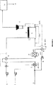
本発明は、本発明に係る燃料電池システムの実施形態を概略的に示した添付の図面に例示されているが、これはこのように限定するものではない。より詳細には、図面は、オートサーマル改質器(2)に運ばれる燃料供給ストリーム(1)を示している。オートサーマル改質器(2)に運ばれる前に、燃料供給ストリーム(1)は加熱される(不図示)。オートサーマル改質器(2)において、燃料供給ストリーム(1)は、触媒部分酸化及びスチーム改質がなされ、それにより、ある濃度のメタンを有する燃料電池供給ストリームを生成する。酸化剤である空気(3)を、熱風用送風器を使用してオートサーマル改質器(2)に供給し、燃料供給ストリームの触媒部分酸化を行う。初期状態では、オートサーマル改質器(2)は、スチームを利用することができないので、枯渇した状態である。示された実施の形態では、オートサーマル改質器(2)を、400−650℃の温度で作動させる。その後、脱硫ユニット(5)に供給される前に、オートサーマル改質器(2)から排出される燃料電池供給ストリームを、冷却器(4)を使用して冷却する。この脱硫ユニット(5)は、およそ380℃で作動している。さらに、脱硫ユニット(5)は、燃料電池供給ストリーム中に存在する硫黄含有有機化合物を硫化水素に変換するための水素化触媒と、硫化水素吸収体(一般的にZnO)とを含む。脱硫された燃料電池供給ストリームを、燃料予備加熱器(6)を使用して550−650℃の温度まで予め加熱し、燃料電池のアノード(7)まで運ぶ。図面には示していないけれども、この燃料電池は、多層燃料電池を含む燃料電池セルスタックである。アノードからの排出物を、熱風用送風機(8)を使用して、オートサーマル改質器(2)まで再循環させても良い。燃料電池アノード(7)及びカソード(10)からの排出ストリームを排熱回復ユニット(12)に供給し、最終排出ストリーム(13)を得ることができる。 The present invention is illustrated in the accompanying drawings, which schematically illustrate embodiments of a fuel cell system according to the present invention, but is not limited thereto. More particularly, the drawing shows a fuel feed stream (1) that is carried to an autothermal reformer (2). Prior to being transported to the autothermal reformer (2), the fuel feed stream (1) is heated (not shown). In the autothermal reformer (2), the fuel feed stream (1) is subjected to catalytic partial oxidation and steam reforming, thereby producing a fuel cell feed stream having a certain concentration of methane. Air (3), which is an oxidant, is supplied to the autothermal reformer (2) using a blower for hot air, and catalytic partial oxidation of the fuel supply stream is performed. In the initial state, the autothermal reformer (2) is in a depleted state because steam cannot be used. In the embodiment shown, the autothermal reformer (2) is operated at a temperature of 400-650 ° C. Thereafter, the fuel cell supply stream discharged from the autothermal reformer (2) is cooled using the cooler (4) before being supplied to the desulfurization unit (5). This desulfurization unit (5) operates at approximately 380 ° C. Further, the desulfurization unit (5) includes a hydrogenation catalyst for converting a sulfur-containing organic compound present in the fuel cell supply stream into hydrogen sulfide, and a hydrogen sulfide absorber (generally ZnO). The desulfurized fuel cell feed stream is preheated to a temperature of 550-650 ° C. using a fuel preheater (6) and conveyed to the fuel cell anode (7). Although not shown in the drawings, the fuel cell is a fuel cell stack including a multilayer fuel cell. The discharge from the anode may be recirculated to the autothermal reformer (2) using a hot air blower (8). The exhaust stream from the fuel cell anode (7) and cathode (10) can be supplied to the exhaust heat recovery unit (12) to obtain the final exhaust stream (13).
空気(9)を、熱風用送風機を介して燃料電池のカソード(10)に供給する。燃料電池内において、電気を発熱反応により発生させる。アノード(7)において、燃料電池供給ストリームに存在するメタンを吸熱反応により内部改質する。反応に必要な熱は、燃料電池内で起こる発熱性発電反応により供給される。制御ユニット(不図示)は、燃料電池の温度を測定し、オートサーマル改質器のオペレーションを変更して、燃料電池供給ストリーム中のメタン濃度を適切なレベルに調整する。適切なレベルとは、燃料電池内のメタンの内部改質が適切な程度で行われ、そのことにより燃料電池の温度の制御が可能となるようなレベルである。燃料電池に対する負荷需要が増加する場合、温度も増加する。この場合、燃料電池供給ストリーム中のメタンを増加させ、そのことにより燃料電池内の内部改質が増加するように、オートサーマル改質器(2)を作動させる。結果として燃料電池内で吸熱性改質反応が増加することにより、燃料電池により発生した付加的な熱を消費する。燃料電池に対する負荷需要が低下するとき、その温度も低下し、オートサーマル改質オペレーションを調整して、燃料電池供給ストリーム中のメタン濃度を減少させる。このメタンの濃度は、燃料電池内で発電反応により発生した熱を消費するのに必要な内部改質に対するメタン量と比例している。 Air (9) is supplied to the cathode (10) of the fuel cell via a hot air blower. In the fuel cell, electricity is generated by an exothermic reaction. At the anode (7), methane present in the fuel cell supply stream is internally reformed by an endothermic reaction. The heat required for the reaction is supplied by an exothermic power generation reaction that occurs in the fuel cell. A control unit (not shown) measures the temperature of the fuel cell and changes the operation of the autothermal reformer to adjust the methane concentration in the fuel cell feed stream to an appropriate level. The appropriate level is a level at which the internal reforming of methane in the fuel cell is performed to an appropriate degree, and thereby the temperature of the fuel cell can be controlled. As the load demand on the fuel cell increases, the temperature also increases. In this case, the autothermal reformer (2) is operated so that the methane in the fuel cell supply stream is increased, thereby increasing the internal reforming in the fuel cell. As a result, the endothermic reforming reaction increases in the fuel cell, thereby consuming additional heat generated by the fuel cell. As the load demand on the fuel cell decreases, its temperature also decreases and adjusts the autothermal reforming operation to reduce the methane concentration in the fuel cell feed stream. The concentration of methane is proportional to the amount of methane for internal reforming required to consume the heat generated by the power generation reaction in the fuel cell.
この明細書及びこれに続く請求の範囲を通して、"comprise"のような用語及び"comprises"や"comprising"のような変化形は、規定された構成要素若しくはステップ又は構成要素若しくはステップのグループを含有することを意味し、他の構成要素若しくはステップ又は構成要素若しくはステップのグループを除外するものではない。 Throughout this specification and the claims that follow, terms such as "comprise" and variations such as "comprises" and "comprising" include the specified component or step or group of components or steps. Does not exclude other components or steps or groups of components or steps.
Claims (14)
所定の濃度のメタンを含有する燃料電池供給ストリームを生成させるため、オートサーマル改質器内で燃料供給ストリームを処理する工程と、
上記燃料電池供給ストリーム中に含まれるメタンを燃料電池内において吸熱性の改質反応により改質し、上記吸熱性の改質反応を、上記発熱性の発電反応により生成された熱のヒートシンクとして使用する工程と、を有し、
燃料電池内において、当該燃料電池の所望の温度制御に適するメタン改質レベルに達するように、上記燃料電池供給ストリーム中のメタン濃度を、オートサーマル改質器のオペレーションを制御することにより変動させることを特徴とする方法。 A method of controlling the temperature of a fuel cell so that heat generated by an exothermic power generation reaction in the fuel cell changes according to load demand on the fuel cell ,
Processing the fuel feed stream in an autothermal reformer to produce a fuel cell feed stream containing a predetermined concentration of methane;
Methane contained in the fuel cell supply stream reforming the endothermic reforming reaction in the fuel cell, using the endothermic reforming reaction, as a heat sink produced by the power generation reaction of the exothermic And a step of
In the fuel cell, to reach the methane reforming level suitable for the desired temperature control of the fuel cell, the methane concentration in the fuel cell supply stream, be varied by controlling the operation of the autothermal reformer A method characterized by.
当該一連のチャンネルは、上記燃料供給ストリームと上記オートサーマル改質器内の触媒との間の、要求される接触の程度に基づいて、上記燃料供給ストリームが、選択されたチャンネルを流れるように構成され、
そのことにより上記燃料電池フィードストリーム中のメタン濃度を制御する請求項1記載の方法。The autothermal reformer is provided with a series of channels of a catalyst coated channel and an uncoated channel,
The series of channels is configured such that the fuel supply stream flows through the selected channel based on the degree of contact required between the fuel supply stream and the catalyst in the autothermal reformer. And
The method of claim 1, wherein the method controls methane concentration in the fuel cell feedstream.
メタン濃度が制御された排出ストリームを生成するため、可変のオペレーションが可能であり、燃料電池の上流において該燃料電池と連通するように設けられたオートサーマル改質器と、
内部でメタンを改質するために適用され、上記オートサーマル改質器の下流において該オートサーマル改質器と連通するように設けられた燃料電池と、を備えるシステム。 A fuel cell system suitable for performing the method of claim 1 , comprising:
An autothermal reformer provided to communicate with the fuel cell upstream of the fuel cell, allowing variable operation to produce a methane concentration controlled exhaust stream;
A fuel cell that is applied to reform methane inside and is provided in communication with the autothermal reformer downstream of the autothermal reformer.
Applications Claiming Priority (3)
| Application Number | Priority Date | Filing Date | Title |
|---|---|---|---|
| AUPS0243A AUPS024302A0 (en) | 2002-01-31 | 2002-01-31 | Thermal management of fuel cells |
| AUPS0243 | 2002-01-31 | ||
| PCT/AU2003/000029 WO2003065488A1 (en) | 2002-01-31 | 2003-01-23 | Thermal managment of fuel cells |
Publications (3)
| Publication Number | Publication Date |
|---|---|
| JP2005516374A JP2005516374A (en) | 2005-06-02 |
| JP2005516374A5 JP2005516374A5 (en) | 2006-02-16 |
| JP4782985B2 true JP4782985B2 (en) | 2011-09-28 |
Family
ID=3833844
Family Applications (1)
| Application Number | Title | Priority Date | Filing Date |
|---|---|---|---|
| JP2003564967A Expired - Fee Related JP4782985B2 (en) | 2002-01-31 | 2003-01-23 | Thermal management method for fuel cell |
Country Status (6)
| Country | Link |
|---|---|
| US (1) | US7521139B2 (en) |
| EP (1) | EP1470605B1 (en) |
| JP (1) | JP4782985B2 (en) |
| AU (2) | AUPS024302A0 (en) |
| CA (1) | CA2474270C (en) |
| WO (1) | WO2003065488A1 (en) |
Families Citing this family (22)
| Publication number | Priority date | Publication date | Assignee | Title |
|---|---|---|---|---|
| MXPA06013098A (en) | 2004-05-28 | 2007-04-27 | Hyradix Inc | Hydrogen generation process using partial oxidation/steam reforming. |
| JP4696513B2 (en) * | 2004-09-27 | 2011-06-08 | トヨタ自動車株式会社 | Fuel cell system |
| US7998632B2 (en) | 2005-05-20 | 2011-08-16 | Delphi Technologies, Inc. | Anode tail gas recycle cooler and re-heater for a solid oxide fuel cell stack assembly |
| US20060292410A1 (en) * | 2005-06-28 | 2006-12-28 | Andreas Kaupert | Fuel cell system for a vehicle |
| EP1739777B1 (en) * | 2005-06-28 | 2014-01-22 | Eberspächer Climate Control Systems GmbH & Co. KG. | Fuel cell system for vehicles |
| DE102006014197A1 (en) * | 2006-03-28 | 2007-10-04 | Bayerische Motoren Werke Ag | Operating procedure for fuel cell system with reformer for hydrogen production and with unit, by heating the system components at operation temperature after starting the system, and recirculating partial quantity of reformat in reformer |
| GB0621784D0 (en) | 2006-11-01 | 2006-12-13 | Ceres Power Ltd | Fuel cell heat exchange systems and methods |
| US8123826B2 (en) | 2006-11-08 | 2012-02-28 | Saudi Arabian Oil Company | Process for the conversion of oil-based liquid fuels to a fuel mixture suitable for use in solid oxide fuel cell applications |
| US20080292922A1 (en) * | 2007-05-22 | 2008-11-27 | Fischer Bernhard A | Method and apparatus for fueling a solid oxide fuel cell stack assembly |
| WO2008147860A1 (en) * | 2007-05-22 | 2008-12-04 | Praxair Technology, Inc. | Dual mode reactor smr integration |
| JP5463006B2 (en) * | 2008-03-14 | 2014-04-09 | Jx日鉱日石エネルギー株式会社 | Operation method of solid oxide fuel cell system |
| JP2011522375A (en) | 2008-05-30 | 2011-07-28 | コーニング インコーポレイテッド | Solid oxide fuel cell system |
| US8808654B2 (en) | 2009-09-29 | 2014-08-19 | Praxair Technology, Inc. | Process for sulfur removal from refinery off gas |
| FI20105377L (en) * | 2010-04-12 | 2011-10-13 | Waertsilae Finland Oy | Method and device for controlling fuel supply in a fuel cell system |
| US8920732B2 (en) | 2011-02-15 | 2014-12-30 | Dcns | Systems and methods for actively controlling steam-to-carbon ratio in hydrogen-producing fuel processing systems |
| JP6096402B2 (en) * | 2011-05-19 | 2017-03-15 | 本田技研工業株式会社 | Fuel cell system |
| WO2014013061A1 (en) * | 2012-07-20 | 2014-01-23 | Topsøe Fuel Cell A/S | Method and easy maintenance reactor assembly for the processing of hydrocarbon fuels |
| JP6374273B2 (en) * | 2014-08-29 | 2018-08-15 | 本田技研工業株式会社 | Fuel cell module |
| KR20200002058A (en) * | 2018-06-29 | 2020-01-08 | 주식회사 경동나비엔 | Reformer and fuel cell system having the same |
| US11542159B2 (en) * | 2020-06-22 | 2023-01-03 | Saudi Arabian Oil Company | Autothermal reformer system with liquid desulfurizer for SOFC system |
| WO2022178439A1 (en) * | 2021-02-22 | 2022-08-25 | Fluor Technologies Corporation | Improved gas reformer for producing hydrogen |
| GB2604593B (en) | 2021-03-03 | 2024-01-24 | Ceres Ip Co Ltd | Fuel cell system |
Family Cites Families (13)
| Publication number | Priority date | Publication date | Assignee | Title |
|---|---|---|---|---|
| US4522894A (en) * | 1982-09-30 | 1985-06-11 | Engelhard Corporation | Fuel cell electric power production |
| US5169730A (en) * | 1990-07-25 | 1992-12-08 | Westinghouse Electric Corp. | Electrochemical cell apparatus having an exterior fuel mixer nozzle |
| US5084362A (en) * | 1990-08-29 | 1992-01-28 | Energy Research Corporation | Internal reforming molten carbonate fuel cell system with methane feed |
| JPH07230819A (en) | 1994-02-16 | 1995-08-29 | Tokyo Gas Co Ltd | Internally modified solid electrolyte fuel cell system having self-heat exchange type heat insulating prereformer |
| JPH07272741A (en) | 1994-03-31 | 1995-10-20 | Mitsubishi Heavy Ind Ltd | Module structure for cylindrical solid electrolytic fuel cell |
| JP3316393B2 (en) * | 1996-09-25 | 2002-08-19 | 三菱電機株式会社 | Fuel cell power generation system and operation method thereof |
| JP3071158B2 (en) | 1997-07-02 | 2000-07-31 | 溶融炭酸塩型燃料電池発電システム技術研究組合 | Fuel cell power generator |
| DE69932869T2 (en) | 1998-06-09 | 2006-12-07 | Idemitsu Kosan Co. Ltd. | Process for the autothermal steam reforming of a hydrocarbon feed |
| JP2000084410A (en) | 1998-07-14 | 2000-03-28 | Idemitsu Kosan Co Ltd | Preparation of autothermal reforming catalyst and production of hydrogen or synthesis gas |
| CA2298970A1 (en) * | 1999-03-18 | 2000-09-18 | Joseph Jay Hartvigsen | Solid oxide fuel cell burner system and method for generating heat therefrom |
| AUPQ223499A0 (en) | 1999-08-16 | 1999-09-09 | Ceramic Fuel Cells Limited | Fuel cell system |
| JP3781942B2 (en) | 2000-03-24 | 2006-06-07 | 東京瓦斯株式会社 | Solid oxide fuel cell system |
| AUPR324201A0 (en) * | 2001-02-21 | 2001-03-15 | Ceramic Fuel Cells Limited | Fuel cell system |
-
2002
- 2002-01-31 AU AUPS0243A patent/AUPS024302A0/en not_active Abandoned
-
2003
- 2003-01-23 WO PCT/AU2003/000029 patent/WO2003065488A1/en active Application Filing
- 2003-01-23 JP JP2003564967A patent/JP4782985B2/en not_active Expired - Fee Related
- 2003-01-23 CA CA2474270A patent/CA2474270C/en not_active Expired - Fee Related
- 2003-01-23 AU AU2003201391A patent/AU2003201391B2/en not_active Ceased
- 2003-01-23 US US10/502,957 patent/US7521139B2/en not_active Expired - Fee Related
- 2003-01-23 EP EP03700081A patent/EP1470605B1/en not_active Expired - Lifetime
Also Published As
| Publication number | Publication date |
|---|---|
| JP2005516374A (en) | 2005-06-02 |
| EP1470605B1 (en) | 2012-12-05 |
| EP1470605A1 (en) | 2004-10-27 |
| US7521139B2 (en) | 2009-04-21 |
| CA2474270C (en) | 2011-10-18 |
| WO2003065488A1 (en) | 2003-08-07 |
| US20050074642A1 (en) | 2005-04-07 |
| EP1470605A4 (en) | 2008-07-30 |
| AU2003201391B2 (en) | 2008-11-06 |
| CA2474270A1 (en) | 2003-08-07 |
| AUPS024302A0 (en) | 2002-02-21 |
Similar Documents
| Publication | Publication Date | Title |
|---|---|---|
| JP4782985B2 (en) | Thermal management method for fuel cell | |
| JP4515253B2 (en) | Fuel cell system | |
| US5458857A (en) | Combined reformer and shift reactor | |
| US7674445B2 (en) | Method for purifying hydrogen in a reformed gas | |
| US5769909A (en) | Method and apparatus for desulfurizing fuel gas | |
| AU2003201391A1 (en) | Thermal managment of fuel cells | |
| US20070190374A1 (en) | Carbon monoxide transforming apparatus for fuel cell and fuel cell power generating system | |
| US6793698B1 (en) | Fuel processor reactor with integrated pre-reforming zone | |
| US6342197B1 (en) | Multi-stage combustion for fuel processing for use with fuel cell | |
| EP1148024A1 (en) | Apparatus for producing hydrogen gas and fuel cell system using the same | |
| US20070275278A1 (en) | Integrated catalytic and turbine system and process for the generation of electricity | |
| JP3071158B2 (en) | Fuel cell power generator | |
| KR100647331B1 (en) | Shift reactor, fuel cell system employing the same, and operating method of the same | |
| US6824904B2 (en) | Reactor for preferential oxidation and method of use | |
| US20040177554A1 (en) | WGS reactor incorporated with catalyzed heat exchanger for WGS reactor volume reduction | |
| JP4753506B2 (en) | Hydrogen-containing gas generator and method for operating the same | |
| JP2002308604A (en) | Fuel reformer | |
| JP4484585B2 (en) | Reformer | |
| JP4446672B2 (en) | Operation control system for carbon monoxide remover and operation control system for fuel cell system | |
| JP4442204B2 (en) | Fuel cell power generation system | |
| KR20080005998A (en) | Process for operating a fuel cell arrangement and fuel cell arrangement | |
| JP2008137866A (en) | Fuel processor and its operation control method | |
| JP2005166580A (en) | Fuel reformer, fuel cell system and operation control method thereof | |
| JP2004119059A (en) | Reforming system for fuel cell | |
| JP2002068705A (en) | Hydrogen producing method |
Legal Events
| Date | Code | Title | Description |
|---|---|---|---|
| A521 | Request for written amendment filed |
Free format text: JAPANESE INTERMEDIATE CODE: A523 Effective date: 20051219 |
|
| A621 | Written request for application examination |
Free format text: JAPANESE INTERMEDIATE CODE: A621 Effective date: 20051219 |
|
| RD03 | Notification of appointment of power of attorney |
Free format text: JAPANESE INTERMEDIATE CODE: A7423 Effective date: 20070730 |
|
| A131 | Notification of reasons for refusal |
Free format text: JAPANESE INTERMEDIATE CODE: A131 Effective date: 20080311 |
|
| A601 | Written request for extension of time |
Free format text: JAPANESE INTERMEDIATE CODE: A601 Effective date: 20080610 |
|
| A602 | Written permission of extension of time |
Free format text: JAPANESE INTERMEDIATE CODE: A602 Effective date: 20080617 |
|
| A601 | Written request for extension of time |
Free format text: JAPANESE INTERMEDIATE CODE: A601 Effective date: 20080710 |
|
| A602 | Written permission of extension of time |
Free format text: JAPANESE INTERMEDIATE CODE: A602 Effective date: 20080717 |
|
| A601 | Written request for extension of time |
Free format text: JAPANESE INTERMEDIATE CODE: A601 Effective date: 20080808 |
|
| A602 | Written permission of extension of time |
Free format text: JAPANESE INTERMEDIATE CODE: A602 Effective date: 20080815 |
|
| A521 | Request for written amendment filed |
Free format text: JAPANESE INTERMEDIATE CODE: A523 Effective date: 20080910 |
|
| A02 | Decision of refusal |
Free format text: JAPANESE INTERMEDIATE CODE: A02 Effective date: 20090623 |
|
| A521 | Request for written amendment filed |
Free format text: JAPANESE INTERMEDIATE CODE: A523 Effective date: 20091022 |
|
| A911 | Transfer to examiner for re-examination before appeal (zenchi) |
Free format text: JAPANESE INTERMEDIATE CODE: A911 Effective date: 20100113 |
|
| A912 | Re-examination (zenchi) completed and case transferred to appeal board |
Free format text: JAPANESE INTERMEDIATE CODE: A912 Effective date: 20100312 |
|
| A01 | Written decision to grant a patent or to grant a registration (utility model) |
Free format text: JAPANESE INTERMEDIATE CODE: A01 |
|
| A61 | First payment of annual fees (during grant procedure) |
Free format text: JAPANESE INTERMEDIATE CODE: A61 Effective date: 20110708 |
|
| FPAY | Renewal fee payment (event date is renewal date of database) |
Free format text: PAYMENT UNTIL: 20140715 Year of fee payment: 3 |
|
| R150 | Certificate of patent or registration of utility model |
Free format text: JAPANESE INTERMEDIATE CODE: R150 |
|
| R250 | Receipt of annual fees |
Free format text: JAPANESE INTERMEDIATE CODE: R250 |
|
| R250 | Receipt of annual fees |
Free format text: JAPANESE INTERMEDIATE CODE: R250 |
|
| S111 | Request for change of ownership or part of ownership |
Free format text: JAPANESE INTERMEDIATE CODE: R313113 |
|
| R350 | Written notification of registration of transfer |
Free format text: JAPANESE INTERMEDIATE CODE: R350 |
|
| S111 | Request for change of ownership or part of ownership |
Free format text: JAPANESE INTERMEDIATE CODE: R313113 |
|
| R350 | Written notification of registration of transfer |
Free format text: JAPANESE INTERMEDIATE CODE: R350 |
|
| LAPS | Cancellation because of no payment of annual fees |