EP3257411A1 - Verstelleinrichtung für ein haushaltskleingerät mit elektromotor - Google Patents
Verstelleinrichtung für ein haushaltskleingerät mit elektromotor Download PDFInfo
- Publication number
- EP3257411A1 EP3257411A1 EP17175057.3A EP17175057A EP3257411A1 EP 3257411 A1 EP3257411 A1 EP 3257411A1 EP 17175057 A EP17175057 A EP 17175057A EP 3257411 A1 EP3257411 A1 EP 3257411A1
- Authority
- EP
- European Patent Office
- Prior art keywords
- teeth
- adjusting device
- row
- operating element
- engagement
- Prior art date
- Legal status (The legal status is an assumption and is not a legal conclusion. Google has not performed a legal analysis and makes no representation as to the accuracy of the status listed.)
- Granted
Links
Images

Classifications
-
- A—HUMAN NECESSITIES
- A47—FURNITURE; DOMESTIC ARTICLES OR APPLIANCES; COFFEE MILLS; SPICE MILLS; SUCTION CLEANERS IN GENERAL
- A47J—KITCHEN EQUIPMENT; COFFEE MILLS; SPICE MILLS; APPARATUS FOR MAKING BEVERAGES
- A47J43/00—Implements for preparing or holding food, not provided for in other groups of this subclass
- A47J43/04—Machines for domestic use not covered elsewhere, e.g. for grinding, mixing, stirring, kneading, emulsifying, whipping or beating foodstuffs, e.g. power-driven
- A47J43/044—Machines for domestic use not covered elsewhere, e.g. for grinding, mixing, stirring, kneading, emulsifying, whipping or beating foodstuffs, e.g. power-driven with tools driven from the top side
-
- A—HUMAN NECESSITIES
- A47—FURNITURE; DOMESTIC ARTICLES OR APPLIANCES; COFFEE MILLS; SPICE MILLS; SUCTION CLEANERS IN GENERAL
- A47J—KITCHEN EQUIPMENT; COFFEE MILLS; SPICE MILLS; APPARATUS FOR MAKING BEVERAGES
- A47J43/00—Implements for preparing or holding food, not provided for in other groups of this subclass
- A47J43/04—Machines for domestic use not covered elsewhere, e.g. for grinding, mixing, stirring, kneading, emulsifying, whipping or beating foodstuffs, e.g. power-driven
- A47J43/044—Machines for domestic use not covered elsewhere, e.g. for grinding, mixing, stirring, kneading, emulsifying, whipping or beating foodstuffs, e.g. power-driven with tools driven from the top side
- A47J2043/04409—Apparatus of hand held type
- A47J2043/04418—Apparatus of hand held type with housing extending perpendicular, e.g. horizontally, from the tool axis
-
- A—HUMAN NECESSITIES
- A47—FURNITURE; DOMESTIC ARTICLES OR APPLIANCES; COFFEE MILLS; SPICE MILLS; SUCTION CLEANERS IN GENERAL
- A47J—KITCHEN EQUIPMENT; COFFEE MILLS; SPICE MILLS; APPARATUS FOR MAKING BEVERAGES
- A47J43/00—Implements for preparing or holding food, not provided for in other groups of this subclass
- A47J43/04—Machines for domestic use not covered elsewhere, e.g. for grinding, mixing, stirring, kneading, emulsifying, whipping or beating foodstuffs, e.g. power-driven
- A47J43/044—Machines for domestic use not covered elsewhere, e.g. for grinding, mixing, stirring, kneading, emulsifying, whipping or beating foodstuffs, e.g. power-driven with tools driven from the top side
- A47J2043/04409—Apparatus of hand held type
- A47J2043/04427—Apparatus of hand held type with housing extending vertically in line with the tool axis
Definitions
- Small household appliances with an electric motor such as kitchen appliances or other portable kitchen appliances, especially stirrers, blenders, microwave ovens, electric knives, juicers or the like with a weight of preferably not more than 15 kg often have at least one adjustment, which includes a pivotable about an axis control.
- a pivoting or a rotation
- an operator of such an adjustment device can usually change at least one operating parameter of the device, for example a number of revolutions of a rotating element.
- the control element may be formed, for example, as a knob or as a lever, which are then mounted in each case pivotable about an axis.
- a locking mechanism may be provided which prevents continuous pivoting and which also holds the control element in the respective position, as long as a force applied for pivoting force of a certain minimum strength triggers the locking.
- Such adjusting devices have the disadvantage that the necessary minimum strength for releasing the locking (when pivoting the operating element) must be relatively low in order to allow a reasonably simple adjustment of the operating element, but that thereby an operator only insufficient feedback on the extent of him receives adjustment and therefore he can control these poor. As a result, inadvertent settings can be made inadvertently by the operator.
- the object of the present invention is to provide a technique which enables a simple and precise control functionality for setting at least one operating parameter of a household small appliance with an electric motor.
- the present invention further has the object, a small household appliance, the one Electric motor has to provide with a precisely controllable adjustment option of an operating parameter.
- the adjusting device has a latching mechanism for releasably holding the operating element in a respective pivoting position; unless a force applied for pivoting force of a certain minimum thickness is applied, the latching mechanism thus holds the control element in its current position.
- the operating element of an adjusting device according to the invention also has a row of teeth, which comprises a plurality of teeth arranged one after the other in the pivoting direction (with respect to the axis in the direction of rotation) of the operating element.
- the row of teeth serves to or is adapted to cooperate with an engagement element when such an engagement element is stationary or fixed relative to the operating element (for example on the small household appliance, in particular on a component of the adjusting device) and engages in the row of teeth.
- the teeth may form a projection of the operating element in the radial direction and / or in the axial direction, based on the (pivoting) axis of the operating element. They are preferably substantially the same shape. For example, they may each be substantially serrated (eg with a triangular or trapezoidal cross-section) or wave-like.
- Each tooth preferably has two flanks, between which lies a (possibly rounded) tooth tip. Between adjacent flanks of adjacent teeth of the row of teeth, a tooth space is preferably formed in each case. According to an exemplary embodiment, an angle between such adjacent flanks of adjacent teeth of the row of teeth at least 50 °, more preferably at least 55 ° and / or at most 75 °, more preferably at most 65 °.
- An adjusting device has the advantage that it can be improved in a simple, advantageous manner or mounted so that it provides a precise control functionality for setting the respective pivoting position:
- the engagement element as an additional element attached to a component of the adjustment be or be that it engages in a tooth space of the row of teeth. If the operating element is then pivoted so that the interdental space of the row of teeth changes, in which the engagement element engages, then a noise is generated in each case which allows an operator precise acoustic feedback about the extent of the pivoting. This allows the accuracy of the adjustment to be controlled, allowing the operator to systematically control the adjustment. In particular, the security can be increased when using the small household appliance.
- An inventive household small appliance with electric motor comprises an adjusting device according to the invention according to one of the embodiments disclosed in this document. It may for example be a small kitchen appliance, in particular a food processor, a mixer, an electric knife, a juicer, a blender, a blender or the like.
- the small household appliance has a mechanism by which one of several possible operating parameters (e.g., the electric motor and / or a mechanical component (such as a distance or angle between two elements of the household appliance)) can be adjusted by virtue of a respective pivot position of the control.
- the locking mechanism can be realized for example by an interaction of two interlocking locking elements, one of which is arranged on the control element and a fixed in or on household small appliance (eg on a housing thereof) is arranged.
- a first of the latching elements may comprise a latching profile (in particular a tip or shaft profile) and a second latching element may comprise a web which is adapted to engage in a latching notch (for example a lintel). or wave space) of the locking profile, wherein the respective notch can be changed by pivoting the operating element.
- an adjusting device comprises at least one housing and / or frame element of the household small appliance.
- a bearing of the operating element and / or at least one fixed latching element of the latching mechanism is integrally formed or fastened to such an element.
- the control element may e.g. be designed as a pivotable lever or as a knob, wherein each of the respective (pivot) axis may extend substantially perpendicular to a surface of a housing member of the household small appliance, or the control element may for example have a form of a rotatable roller basic shape whose axis substantially parallel to a surface tangent of a housing element of the household small appliance runs (and on which - as mentioned - a bearing of the operating element and / or a component of the latching mechanism can be molded or fixed can / can).
- the pivoting of the operating element is preferably in an angular range in two directions of rotation (ie back and forth) possible; Alternatively, the operating element can be pivoted indefinitely in exactly one direction (by an arbitrarily large angle, in particular 360 °).
- the operating element is adapted to pierce a housing of the household small appliance and thus have a user-accessible area and a concealed area by the housing; if the adjusting device comprises at least one housing element, the operating element can accordingly be arranged such that it pierces through this housing element (s).
- the operating element preferably penetrates at least one housing element of the household small appliance.
- the latching mechanism and / or the row of teeth of the operating element and / or a bearing of the operating element is adapted to be disposed within a housing of the household small appliance (in particular in a hidden area of the housing); in a household small appliance according to the invention the latching mechanism and / or the row of teeth and / or a storage of the control element is preferably arranged analogously within a housing (in particular in a hidden area of the housing) of the household small appliance. In this way, the latching mechanism or the row of teeth or storage is particularly protected against mechanical influences and contamination.
- the adjusting device comprises at least one fastening means for holding the engagement element.
- the fastening means is thus adapted to be equipped with the engagement element and in such a fitted state, the engagement element releasably fixed to support so that the engagement element cooperates with the row of teeth that engages, for example, a portion of the engagement member in a tooth space of the row of teeth.
- the row of teeth In an unpopulated state of the fastener, in which therefore no engagement element is supported by this, the row of teeth, however, preferably runs freely, so has no contact with another component of the adjustment or the Margsklein réelles.
- Such an embodiment enables a simple, optional improvement of the adjusting device or of the household small appliance by fastening the engagement element with the fastening element, if an improved control option for a pivoting is to be offered.
- the embodiment allows a particularly simple replacement of the engagement element, for example, if it is damaged as a wearing part.
- Such a fastening element is preferably adapted in its size and / or shape to the engagement element, which is provided or furnished to hold it.
- the fastening element can be configured to hold the engagement element in a positive and / or non-positive manner.
- the fastening element may for example comprise at least one receiving frame at least for a portion of the engagement element, at least one retaining rail, at least one clamping device and / or at least one screw.
- the adjusting device comprises the engagement element, which is preferably arranged or arranged stationary on the adjusting device and is adapted to adjustably engage in the row of teeth of the operating element.
- the engagement member may be fixedly connected (e.g., bonded) (e.g., welded or monolithically molded (e.g., by injection molding) to a component of the household appliance such as a frame or housing member of the household appliance, or the engagement member may be releasably secured.
- the engagement member is preferably adapted to - in relation to the axis of the operating element - axial or radial direction to intervene in each case a tooth space between two teeth of the row of teeth, on pivoting of the operating element in another interdental space and to produce a noise at such a crossing.
- the engagement element may, for example, comprise a spring tongue with a free end for engagement with the row of teeth.
- the spring tongue can be formed of metal or plastic.
- the engagement element comprises a spring element with at least one yielding section which has at least one curvature.
- the spring element engages with the curvature in the row of teeth of the operating element or is adapted to intervene with the curvature in the row of teeth of the operating element.
- the at least one curvature is preferably adapted to an interdental space of the row of teeth, for example such that it essentially simulates the interdental space in its shape at least in one section, that is, extends substantially along two adjacent flanks of adjacent teeth in contact with the row of teeth.
- Such a spring element is preferably designed to be capable of oscillating in a region of the spring element which extends beyond the at least one curvature and has, for example, at least twice the area as the curvature. Thereby, a suitable, in particular not too high-frequency noise by vibration of the spring element due to an interaction with the row of teeth can be generated.
- a spring element with at least one curvature which is designed as a strip which is substantially flat in an area outside the curvature.
- the spring element may, for example, entirely or partially made of plastic and / or metal.
- the engagement element comprises a holder in which the spring element is held under tension.
- the holder can in particular a have adapted to a fastener of the adjustment form, for example, be set up to enter into a positive and / or positive connection with such a fastener.
- Particularly advantageous is an embodiment in which the holder forms a resonator for the spring element;
- the holder can form a hollow body.
- the holder may be wholly or partially made of plastic and / or metal. In particular, it may consist of a different material than the spring element.
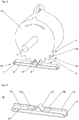
- FIG. 1 is a perspective, schematic representation of an insight into an exemplary embodiment of an adjusting device according to the invention for a small household appliance with electric motor shown.
- a small household appliance can be, for example, in particular a hand mixer, a blender, a microwave oven, an electric knife, a juicer or the like.
- the adjusting device comprises an operating element 10, which - as indicated by the double arrow, is mounted pivotably about an axis A by means of bearings 110; a corresponding angular range in which the pivoting is possible is limited by a handle portion 12 of the operating element and an opening 111 (shown only in one section) of a housing element 100 which penetrates the handle portion 12; the opening extends into a cover, which is not shown, to allow the intended insight into the household small appliance.
- the adjusting device has a latching mechanism 40 for releasably holding the operating element in a respective pivoting position, which is formed in the example shown by a web 15 on the operating element 10 and a locking profile 20 with prongs, which is fixed to the housing element 100.
- the web 15 of the operating element 10 engages in the latching profile 20 and is held by its teeth in a respective position until a force required for pivoting force of a minimum thickness is applied by a user. In this case, the web 15 slides in the locking profile accordingly.
- the operating element 10 also has a row of teeth 11 with teeth, of which in the FIG. 1
- the teeth 11a, 11b, 11c are provided with reference numerals.
- the teeth 11a, 11b, 11c each form a projection of the operating element 10 in the radial direction.
- the row of teeth 11 is arranged to be stationary with a non-illustrated, optionally available (for example, arranged immovably relative to the housing element 100, in particular on this or a frame element of the small household appliance fixed) engaging element:
- Such an engagement element can engage in at least one dependent of a pivoting position of the operating element tooth space.
- a pivoting of the operating element then causes a position of such an engagement element to change from a first interdental space into a second interdental space.
- a noise is preferably generated, which provides a user with an acoustic feedback on the pivoting.
- the in the FIG. 1 adjusting device shown further comprises a fastening element 30 which is formed in the illustrated embodiment as a rectangular receptacle into which one end of a suitable engagement member for attachment can be partially inserted;
- the adjusting device comprises the fastening element 30 with respect to an analog (not shown) further fastening element into which a second end of such engagement element can be inserted, so that it is then attached at both ends.
- the fastener 30 is not populated, thus holding no engagement element.
- the row of teeth 11 of the operating element 10 is free, so it has no potential pivot position in contact with another element of the adjustment.
- the fastener thus allows an optional upgrade of the adjustment or the small household appliance with an engaging element and thus with an improved control functionality for a degree of pivoting of the operating element 10. In addition, it allows easy replacement of such engagement element.
- FIG. 2 schematically shows how a row of teeth 11 of a control element and an engagement element 50, which in this case comprises a spring element 52, cooperate.
- an engagement element is suitable, for example, for insertion into an in FIG. 1 shown recording 30 of the adjustment.
- the spring element 52 which may be made of metal and / or plastic, for example, is designed as a strip, the ends of which are fastened to a holder 51. Between the corresponding fastening points, the spring element comprises a yielding section which has a curvature 53.
- the curvature 53 is in the illustrated embodiment in a Area of its maximum (which is formed between the curvature forming flanks) shaped according to a tooth space of the row of teeth 11 of the operating element 10, in which it engages:
- the interdental spaces are each formed by an adjacent flanks 14 a, 14 b of adjacent teeth of the row of teeth, the one Include angle ⁇ .
- the angle ⁇ is at least 50 °, more preferably at least 55 ° and / or at most 75 °, more preferably at most 60 °.
- the spring element 52 In an environment of the bulge 53 of the spring element 52 (in the FIG. 2 right and left of the curvature), the spring element 52 is substantially planar. As a result, in each case only two adjacent teeth of the row of teeth 11 come into contact with the spring element, which ensures a low resistance during pivoting. Buckle and even environment of the spring element yield to pressure, so are resilient or flexible, and between the spring element 52 and the holder 51, an air space is formed. The spring element can thereby oscillate in this area and generate a noise when the operating element 10 is pivoted and the curvature thereby moves from one interdental space to another.
- the holder 51 forms a soundboard.
- FIG. 3 an alternative engagement element 50 'configured similar to the engagement element 50 is shown in accordance with an exemplary embodiment of the present invention.
- the holder 51 'of the engagement member 50' has a longitudinal wall 55; attached to the longitudinal wall 55 are holding webs 54a, 54b, between which protrudes the curvature 53 of the spring element.
- the webs advantageously allow a fixation of the spring element and a controlled yielding of the curvature when a row of teeth 11 of a control element 10 is pivoted about it.
- the longitudinal wall 55 opposite to another (in FIG. 3 not shown) longitudinal wall of the holder 51 ', so that the holder 51' and the spring element 52 comprehensive engagement element forms a substantially closed, cuboid block, in the interior of an air space 60 is formed.
- Such an engagement element is particularly well in a trained as a recording Fixing fastener and also forms a resonant body, which advantageously amplifies a generated by pivoting the control element noise.
Landscapes
- Engineering & Computer Science (AREA)
- Mechanical Engineering (AREA)
- Food Science & Technology (AREA)
- Food-Manufacturing Devices (AREA)
Abstract
Description
- Haushaltskleingeräte mit einem Elektromotor, beispielsweise Küchenhandgeräte oder sonstige tragbare Küchengeräte, insbesondere Rührgeräte, Standmixer, Mikrowellengeräte, Elektromesser, Saftpressen oder dergleichen mit einem Gewicht von vorzugsweise maximal 15 kg weisen häufig mindestens eine Verstelleinrichtung auf, die ein um eine Achse verschwenkbares Bedienelement umfasst. Mittels einer Verschwenkung (bzw. einer Drehung) kann ein Bediener solch einer Verstelleinrichtung üblicherweise mindestens einen Betriebsparameter des Geräts verändern, beispielsweise eine Umdrehungszahl eines rotierenden Elements. Das Bedienelement kann beispielsweise als Drehknopf ausgebildet sein oder als ein Hebel, die dann jeweils um eine Achse verschwenkbar gelagert sind.
- Damit der Einstellungsvorgang besser kontrolliert werden kann, ermöglichen viele Verstelleinrichtungen lediglich ein stufenweises Verstellen. Dazu kann ein Rastmechanismus vorgesehen sein, der ein kontinuierliches Verschwenken verhindert und der zudem das Bedienelement in der jeweiligen Lage hält, solange nicht eine für ein Verschwenken aufgebrachte Kraft einer gewissen Mindeststärke die Verrastung löst.
- Derartige Verstelleinrichtungen haben den Nachteil, dass die notwendige Mindeststärke für das Lösen der Verrastung (beim Verschwenken des Bedienelements) relativ niedrig sein muss, um ein angemessen einfaches Verstellen des Bedienelements zu ermöglichen, dass dadurch aber ein Bediener nur unzureichende Rückmeldung über das Ausmaß der durch ihn vorgenommenen Verstellung erhält und er diese daher schlecht kontrollieren kann. Dadurch können vom Bediener versehentlich ungeeignete Einstellungen vorgenommen werden.
- Die vorliegende Erfindung hat die Aufgabe, eine Technik bereitzustellen, die eine einfache und präzise Kontrollfunktionalität für eine Einstellung mindestens eines Betriebsparameters eines Haushaltskleingeräts mit Elektromotor ermöglicht. Die vorliegende Erfindung hat weiterhin die Aufgabe, ein Haushaltskleingerät, das einen Elektromotor aufweist, mit einer präzise kontrollierbaren Einstellungsmöglichkeit eines Betriebsparameters bereitzustellen.
- Die Aufgabe wird gelöst durch eine Verstelleinrichtung gemäß Anspruch 1 und ein Haushaltskleingerät gemäß Anspruch 9. Vorteilhafte Ausführungsformen sind in den Unteransprüchen, der Beschreibung und den Figuren offenbart.
- Eine erfindungsgemäße Verstelleinrichtung für ein Haushaltskleingerät mit Elektromotor umfasst ein Bedienelement, das zur Einstellung je einer von mindestens zwei einstellbaren Schwenkstellungen verschwenkbar gelagert ist, also in einem Winkelbereich um eine Achse verschwenkt werden kann.
- Die Verstelleinrichtung weist einen Rastmechanismus zum lösbaren Halten des Bedienelements in einer jeweiligen Schwenkstellung auf; solange nicht eine für ein Verschwenken aufgebrachte Kraft einer gewissen Mindeststärke aufgebracht wird, hält der Rastmechanismus also das Bedienelement in seiner jeweils aktuellen Lage. Das Bedienelement einer erfindungsgemäßen Verstelleinrichtung weist zudem eine Zahnreihe auf, die eine Mehrzahl an in Verschwenkrichtung (bezüglich der Achse also in Umlaufrichtung) des Bedienelements hintereinander angeordneten Zähnen umfasst. Die Zahnreihe dient dazu bzw. ist dazu eingerichtet, mit einem Eingriffselement zusammenzuwirken, wenn ein solches Eingriffselement ortsfest gegenüber dem Bedienelement (z.B. am Haushaltskleingerät, insbesondere an einer Komponente der Verstelleinrichtung) angeordnet bzw. befestigt ist und in die Zahnreihe eingreift.
- Eine derartige Eignung der Zahnreihe kann beispielsweise durch eine entsprechende Form und/oder Anordnung der Zähne realisiert werden. Die Zähne können z.B. - bezogen auf die (Schwenk-) Achse des Bedienelements - in radialer Richtung und/oder in axialer Richtung jeweils einen Vorsprung des Bedienelements ausbilden. Sie sind vorzugsweise im Wesentlichen gleich geformt. Sie können beispielsweise jeweils im Wesentlichen zackenartig (z.B. mit einem dreieckigen oder trapezförmigen Querschnitt) oder wellenartig ausgebildet sein. Jeder Zahn weist vorzugsweise zwei Flanken auf, zwischen denen eine (ggf. gerundete) Zahnspitze liegt. Zwischen benachbarten Flanken benachbarter Zähne der Zahnreihe ist vorzugsweise jeweils ein Zahnzwischenraum ausgebildet. Gemäß einer exemplarischen Ausführungsform beträgt ein Winkel zwischen derartigen benachbarten Flanken benachbarter Zähne der Zahnreihe mindestens 50°, bevorzugter mindestens 55° und/oder höchstens 75°, bevorzugter höchstens 65°.
- Eine erfindungsgemäße Verstelleinrichtung bietet den Vorteil, dass sie in einfacher, vorteilhafter Weise dahingehend aufgebessert bzw. so montiert werden kann, dass sie eine präzise Kontrollfunktionalität für eine Einstellung der jeweiligen Verschwenkstellung bietet: Dazu kann das Eingriffselement als zusätzliches Element so an einer Komponente der Verstelleinrichtung befestigt werden oder sein, dass es in einen Zahnzwischenraum der Zahnreihe eingreift. Wird dann das Bedienelement verschwenkt, so dass sich der Zahnzwischenraum der Zahnreihe ändert, in den das Eingriffselement eingreift, so wird dadurch jeweils ein Geräusch erzeugt, das einem Bediener eine präzise akustische Rückmeldung über das Ausmaß der Verschwenkung ermöglicht. Dadurch kann die Genauigkeit der Einstellung kontrolliert werden, was dem Bediener ein planvolles Regeln der Einstellung ermöglicht. Insbesondere kann so die Sicherheit bei der Verwendung des Haushaltskleingeräts erhöht werden.
- Ein erfindungsgemäßes Haushaltskleingerät mit Elektromotor umfasst eine erfindungsgemäße Verstelleinrichtung gemäß einer der in dieser Schrift offenbarten Ausführungsformen. Es kann beispielsweise ein Küchenkleingerät, insbesondere eine Küchenmaschine, ein Rührgerät, ein Elektromesser, eine Saftpresse, ein Pürierstab, ein Standmixer oder dergleichen sein. Vorzugsweise weist das Haushaltskleingerät einen Mechanismus auf, über den vermöge einer jeweiligen Schwenkstellung des Bedienelements einer von mehreren möglichen Betriebsparametern (z.B. des Elektromotors und/oder einer mechanischen Komponente (wie beispielsweise ein Abstand oder ein Winkel zwischen zwei Elementen des Haushaltskleingeräts)) eingestellt werden kann.
- Der Rastmechanismus kann beispielsweise durch ein Zusammenwirken zweier ineinander eingreifender Rastelemente realisiert werden, von denen eines am Bedienelement angeordnet und eines fix im oder am Haushaltskleingerät (z.B. an einem Gehäuse desselben) angeordnet ist. Insbesondere kann ein erstes der Rastelemente ein Rastprofil (insbesondere ein Spitzen- oder Wellenprofil) umfassen und ein zweites Rastelement einen Steg, der dazu eingerichtet ist, in eine Rastkerbe (z.B. einen Spitzen- bzw. Wellenzwischenraum) des Rastprofils einzugreifen, wobei die jeweilige Rastkerbe durch eine Verschwenkung des Bedienelements geändert werden kann.
- Gemäß einer vorteilhaften Ausführungsform umfasst eine erfindungsgemäße Verstelleinrichtung mindestens ein Gehäuse- und/oder Rahmenelement des Haushaltskleingeräts. Vorzugsweise ist eine Lagerung des Bedienelements und/oder mindestens ein fixes Rastelement des Rastmechanismus' (z.B. ein Steg oder ein Rastprofil, insbesondere ein Spitzen- oder Wellenprofil) an einem derartigen Element angeformt oder befestigt.
- Das Bedienelement kann z.B. als ein verschwenkbarer Hebel oder als ein Drehknopf ausgebildet sein, wobei jeweils die jeweilige (Schwenk-) Achse im Wesentlichen senkrecht zu einer Oberfläche eines Gehäuseelements des Haushaltskleingeräts verlaufen kann, oder das Bedienelement kann beispielsweise eine als drehbare Rolle ausgebildete Grundform aufweisen, deren Achse im Wesentlichen parallel zu einer Oberflächetangente eines Gehäuseelements des Haushaltskleingeräts verläuft (und an dem - wie erwähnt - eine Lagerung des Bedienelements und/oder eine Komponente des Rastmechanismus angeformt oder befestigt sein kann/können).
- Das Verschwenken des Bedienelements ist vorzugsweise in einem Winkelbereich in zwei Drehrichtungen (also vor und zurück) möglich; alternativ kann das Bedienelement in genau eine Richtung unbegrenzt (um einen beliebig großen Winkel, insbesondere 360°) verschwenkbar sein.
- Gemäß einer vorteilhaften Ausführungsform der vorliegenden Erfindung ist das Bedienelement dazu eingerichtet, ein Gehäuse des Haushaltskleingeräts zu durchstoßen und so einen für einen Verwender zugänglichen Bereich und einen durch das Gehäuse verdeckten Bereich aufzuweisen; umfasst die Verstelleinrichtung mindestens ein Gehäuseelement, kann das Bedienelement dementsprechend so angeordnet sein, dass es diese(s) Gehäuseelement(e) durchstößt. Bei einem erfindungsgemäßen Haushaltskleingerät durchstößt analog das Bedienelement vorzugsweise mindestens ein Gehäuseelement des Haushaltskleingeräts.
- Vorteilhafterweise ist der Rastmechanismus und/oder die Zahnreihe des Bedienelements und/oder eine Lagerung des Bedienelements dazu eingerichtet, innerhalb eines Gehäuses des Haushaltskleingeräts (insbesondere in einem durch das Gehäuse verdeckten Bereich) angeordnet zu sein; bei einem erfindungsgemäßen Haushaltskleingerät ist der Rastmechanismus und/oder die Zahnreihe und/oder eine Lagerung des Bedienelements analog vorzugsweise innerhalb eines Gehäuses (insbesondere in einem durch das Gehäuse verdeckten Bereich) des Haushaltskleingeräts angeordnet. Auf diese Weise ist der Rastmechanismus bzw. die Zahnreihe bzw. die Lagerung insbesondere gegen mechanische Einflüsse und Verschmutzung geschützt.
- Gemäß einer vorteilhaften Ausführungsform der vorliegenden Erfindung umfasst die Verstelleinrichtung mindestens ein Befestigungsmittel zum Haltern des Eingriffselements. Das Befestigungsmittel ist dabei also dazu eingerichtet, mit dem Eingriffselement bestückt zu werden und in einem derart bestückten Zustand das Eingriffselement lösbar ortsfest so zu haltern, dass das Eingriffselement mit dem Zahnreihe zusammenwirkt, dass beispielsweise ein Abschnitt des Eingriffselements in einen Zahnzwischenraum der Zahnreihe eingreift. In einem unbestückten Zustand des Befestigungselements, in dem also kein Eingriffselement von diesem gehaltert wird, läuft die Zahnreihe hingegen vorzugsweise frei, hat also keinen Kontakt zu einer anderen Komponente der Verstelleinrichtung bzw. des Haushaltskleingeräts.
- Eine derartige Ausführungsform ermöglicht ein einfaches, optionales Aufbessern der Verstelleinrichtung bzw. des Haushaltskleingeräts durch Befestigen des Eingriffselements mit dem Befestigungselement, wenn eine verbesserte Kontrollmöglichkeit für ein Verschwenken geboten werden soll. Zudem erlaubt die Ausführungsvariante ein besonders einfaches Auswechseln des Eingriffselements, beispielsweise wenn es als Verschleißteil beschädigt ist.
- Ein solches Befestigungselement ist vorzugsweise in seiner Größe und/oder Form an das Eingriffselement angepasst, das zu haltern es vorgesehen bzw. eingerichtet ist. Insbesondere kann das Befestigungselement dazu eingerichtet sein, das Eingriffselement form- und/oder kraftschlüssig zu haltern.
- Das Befestigungselement kann beispielsweise mindestens einen Aufnahmerahmen zumindest für einen Abschnitt des Eingriffselements, mindestens eine Halteschiene, mindestens eine Klemmvorrichtung und/oder mindestens ein Schraubelement umfassen.
- Gemäß einer vorteilhaften Ausführungsform umfasst die Verstelleinrichtung das Eingriffselement, das vorzugsweise ortsfest an der Verstelleinrichtung angeordnet oder anzuordnen sowie dazu eingerichtet ist, in die Zahnreihe des Bedienelements verstellbar einzugreifen. Das Eingriffselement kann mit einer Komponente des Haushaltskleingeräts, beispielsweise mit einem Rahmen- oder Gehäuseelement des Haushaltskleingerät fest (insbesondere stoffschlüssig) verbunden (z.B. angeschweißt oder (z.B. mittels Spritzgussverfahren) monolithisch angeformt) sein, oder das Eingriffselement kann lösbar befestigt bzw. zu befestigen sein. Das Eingriffselement ist vorzugsweise dazu eingerichtet in - bezogen auf die Achse des Bedienelements - axialer oder radialer Richtung in jeweils einen Zahnzwischenraum zwischen zwei Zähnen der Zahnreihe einzugreifen, bei einem Verschwenken des Bedienelements in einen anderen Zahnzwischenraum überzutreten und bei einem derartigen Übertritt ein Geräusch zu erzeugen.
- Das Eingriffselement kann beispielsweise eine Federzunge mit einem freien Ende zum Eingriff in die Zahnreihe umfassen. Die Federzunge kann aus Metall oder Kunststoff gebildet sein.
- In einer vorteilhaften Variante umfasst das Eingriffselement ein Federelement mit mindestens einem nachgebenden Abschnitt, der mindestens eine Wölbung aufweist. Das Federelement greift dabei mit der Wölbung in die Zahnreihe des Bedienelements ein oder ist dazu eingerichtet, mit der Wölbung in die Zahnreihe des Bedienelements einzugreifen. So kann ein Zusammenwirken des Federelements mit der Zahnreihe des Bedienelements herbeigeführt werden.
- Insbesondere ist die mindestens eine Wölbung vorzugsweise an einen Zahnzwischenraum der Zahnreihe angepasst, beispielsweise so, dass sie den Zahnzwischenraum in seiner Form zumindest in einem Abschnitt im Wesentlichen nachbildet, im Kontakt mit der Zahnreihe also im Wesentlichen entlang zweier benachbarter Flanken benachbarter Zähne verläuft.
- Ein solches Federelement ist vorzugsweise in einem über die mindestens eine Wölbung hinausgehenden, beispielsweise mindestens eine doppelt so große Fläche wie die Wölbung aufweisenden Bereich des Federelements schwingfähig ausgebildet. Dadurch kann ein geeignetes, insbesondere nicht zu hochfrequentes Geräusch durch Schwingung des Federelements infolge eines Zusammenwirkens mit der Zahnreihe erzeugt werden.
- Insbesondere vorteilhaft ist eine Ausführungsform eines Federelements mit mindestens einer Wölbung, das als Streifen ausgebildet ist, der in einem Bereich außerhalb der Wölbung im Wesentlichen eben ist.
- Das Federelement kann beispielsweise ganz oder teilweise aus Kunststoff und/oder Metall bestehen.
- Gemäß einer bevorzugten Ausführungsform umfasst das Eingriffselement eine Halterung, in der das Federelement unter Spannung gehalten wird. Die Halterung kann insbesondere eine
an ein Befestigungselement der Verstelleinrichtung angepasste Form haben, beispielsweise dazu eingerichtet sein, eine kraft- und/oder formschlüssige Verbindung mit einem solchen Befestigungsmittel einzugehen. Besonders vorteilhaft ist eine Ausführungsform, bei der die Halterung einen Resonanzkörper für das Federelement bildet; insbesondere kann die Halterung einen Hohlkörper bilden. Die Halterung kann ganz oder teilweise aus Kunststoff und/oder Metall gebildet sein. Insbesondere kann sie aus einem anderen Material bestehen als das Federelement. - Im Folgenden werden bevorzugte Ausführungsbeispiele der Erfindung anhand von Zeichnungen näher erläutert. Es versteht sich, dass einzelne Elemente und Komponenten auch anders kombiniert werden können als dargestellt. Bezugszeichen für einander entsprechende Elemente sind figurenübergreifend verwendet und werden ggf. nicht für jede Figur neu beschrieben.
- Es zeigen schematisch:
- Figur 1:
- eine erfindungsgemäße Verstelleinrichtung gemäß einer exemplarischen Ausführungsform der vorliegenden Erfindung;
- Figur 2:
- ein Bedienelement gemäß einer Ausführungsform der vorliegenden Erfindung im Zusammenwirken mit einem exemplarischen Eingriffselement einer ersten Ausführungsform; und
- Figur 3:
- ein Federelement einer zweiten erfindungsgemäßen Ausführungsform.
- In
Figur 1 ist in perspektivischer, schematischer Darstellung ein Einblick in eine exemplarische Ausführungsform einer erfindungsgemäßen Verstelleinrichtung für ein Haushaltskleingerät mit Elektromotor gezeigt. Ein derartiges Haushaltskleingerät kann beispielsweise insbesondere ein Handrührgerät, ein Standmixer, ein Mikrowellengerät, ein Elektromesser, eine Saftpresse oder dergleichen sein. Vorzugsweise hat es ein Gewicht von maximal 15 kg, bevorzugter von höchstens 8kg oder sogar höchstens 5kg. Die Verstelleinrichtung umfasst ein Bedienelement 10, das - wie durch den Doppelpfeil angegeben, mittels Lagerungen 110 um eine Achse A verschwenkbar gelagert ist; ein entsprechender Winkelbereich, in dem die Verschwenkung möglich ist, ist durch einen Griffabschnitt 12 des Bedienelements und eine (nur in einem Abschnitt gezeigte) Öffnung 111 eines Gehäuseelements 100 beschränkt, das der Griffabschnitt 12 durchstößt; die Öffnung erstreckt sich in eine Abdeckung hinein, die nicht dargestellt ist, um den vorgesehenen Einblick in das Haushaltskleingerät zu ermöglichen. - Die Verstelleinrichtung weist einen Rastmechanismus 40 zum lösbaren Halten des Bedienelements in einer jeweiligen Schwenkstellung auf, der im gezeigten Beispiel durch einen Steg 15 am Bedienelement 10 und ein Rastprofil 20 mit Zacken gebildet ist, das an dem Gehäuseelement 100 fixiert ist. Der Steg 15 des Bedienelements 10 greift in das Rastprofil 20 ein und wird durch dessen Zacken in einer jeweiligen Lage gehalten, bis von einem Verwender eine zum Verschwenken notwendige Kraft einer Mindeststärke aufgebracht wird. In diesem Fall rutscht der Steg 15 in dem Rastprofil entsprechend weiter.
- Das Bedienelement 10 weist zudem eine Zahnreihe 11 mit Zähnen auf, von denen in der
Figur 1 der Übersichtlichkeit halber nur die Zähne 11a, 11 b, 11 c mit Bezugszeichen versehen sind. Bezogen auf die Achse A bilden die Zähne 11a, 11 b, 11 c jeweils einen Vorsprung des Bedienelements 10 in radialer Richtung aus. Damit ist die Zahnreihe 11 dazu eingerichtet, mit einem nicht dargestellten, optional vorhandenen ortsfesten (z.B. relativ zum Gehäuseelement 100 unbeweglich angeordneten, insbesondere an diesem oder einem Rahmenelement des Haushaltskleingeräts fixierten) Eingriffselement zusammenzuwirken: Ein derartiges Eingriffselement kann dabei in mindestens einen von einer Verschwenkstellung des Bedienelements abhängigen Zahnzwischenraum eingreifen. Ein Verschwenken des Bedienelements bewirkt dann also, dass eine Position eines derartigen Eingriffselements von einem ersten Zahnzwischenraum in einen zweiten Zahnzwischenraum wechselt. Dabei wird vorzugsweise ein Geräusch erzeugt, der einem Verwender eine akustische Rückmeldung über das Verschwenken liefert. - Die in der
Figur 1 gezeigte Verstelleinrichtung umfasst ferner ein Befestigungselement 30, das im dargestellten Ausführungsbeispiel als quaderförmige Aufnahme ausgebildet ist, in die ein Ende eines geeigneten Eingriffselements zur Befestigung teilweise eingeschoben werden kann; gemäß einer vorteilhaften Ausführungsform umfasst die Verstelleinrichtung dem Befestigungselement 30 gegenüber ein analoges (nicht gezeigtes) weiteres Befestigungselement, in das ein zweites Ende eines derartigen Eingriffselement eingesetzt werden kann, so dass dieses dann an beiden Enden befestigt ist. Im dargestellten Zustand ist das Befestigungselement 30 nicht bestückt, haltert also kein Eingriffselement. In diesem unbestückten Zustand läuft die Zahnreihe 11 des Bedienelements 10 frei, hat also in keiner möglichen Schwenkstellung Kontakt zu einem anderen Element der Verstelleinrichtung. - Das Befestigungselement ermöglicht somit eine optionale Aufrüstung der Verstelleinrichtung bzw. des Haushaltskleingeräts mit einem Eingriffselement und damit mit einer verbesserten Kontrollfunktionalität für ein Ausmaß einer Verschwenkung des Bedienelements 10. Zudem ermöglicht es einen einfachen Austausch eines derartigen Eingriffselements.
- In
Figur 2 ist schematisch gezeigt, wie eine Zahnreihe 11 eines Bedienelements und ein Eingriffselement 50, das in diesem Falle ein Federelement 52 umfasst, zusammenwirken. Ein derartiges Eingriffselement eignet sich beispielsweise zum Einsetzen in eine inFigur 1 gezeigte Aufnahme 30 der Verstelleinrichtung. Das Federelement 52, das beispielsweise aus Metall und/oder Kunststoff hergestellt sein kann, ist als Streifen ausgebildet, dessen Enden an einer Halterung 51 befestigt sind. Zwischen den entsprechenden Befestigungspunkten umfasst das Federelement einen nachgebenden Abschnitt, der eine Wölbung 53 aufweist. Die Wölbung 53 ist im dargestellten Ausführungsbeispiel in einem Bereich ihres Maximums (das zwischen den die Wölbung ausbildenden Flanken ausgebildet ist) entsprechend einem Zahnzwischenraum der Zahnreihe 11 des Bedienelements 10 geformt, in den es eingreift: Die Zahnzwischenräume sind dabei jeweils durch eine benachbarte Flanken 14a, 14b benachbarter Zähne der Zahnreihe gebildet, die einen Winkel α einschließen. Gemäß vorteilhaften Ausführungsformen beträgt der Winkel α mindestens 50°, bevorzugter mindestens 55° und/oder höchstens 75°, bevorzugter höchstens 60°. - In einer Umgebung der Wölbung 53 des Federelements 52 (in der
Figur 2 rechts und links der Wölbung) ist das Federelement 52 im Wesentlichen eben ausgebildet. Dadurch kommen jeweils nur zwei benachbarte Zähne der Zahnreihe 11 mit dem Federelement in Kontakt, was einen geringen Widerstand beim Verschwenken sicherstellt. Wölbung und ebene Umgebung des Federelements geben auf Druck nach, sind also federnd bzw. flexibel, und zwischen dem Federelement 52 und der Halterung 51 ist ein Luftraum ausgebildet. Das Federelement kann dadurch in diesem Bereich schwingen und ein Geräusch erzeugen, wenn das Bedienelement 10 verschwenkt wird und die Wölbung dabei von einem Zahnzwischenraum in einen anderen wandert. Die Halterung 51 bildet dabei einen Resonanzboden. - In
Figur 3 ist ein alternatives, aber ähnlich dem Eingriffselement 50 aufgebautes Eingriffselement 50' gemäß einer exemplarischen Ausführungsform der vorliegenden Erfindung gezeigt. Im Unterschied zum Eingriffselement 50 weist die Halterung 51' des Eingriffselements 50' eine Längswand 55 auf; an der Längswand 55 befestigt sind Haltestege 54a, 54b, zwischen denen die Wölbung 53 des Federelements hervorragt. Die Stege ermöglichen vorteilhaft eine Fixierung des Federelements und eine kontrolliertes Nachgeben der Wölbung, wenn eine Zahnreihe 11 eines Bedienelements 10 darüber verschwenkt wird. - Vorzugsweise ist der Längswand 55 gegenüber eine weitere (in
Figur 3 nicht gezeigte) Längswand der Halterung 51' angeordnet, so dass das die Halterung 51' und das Federelement 52 umfassende Eingriffselement einen im Wesentlichen geschlossenen, quaderartigen Block bildet, in dessen Innerem ein Luftraum 60 ausgebildet ist. Ein derartiges Eingriffselement ist besonders gut in einem als Aufnahme ausgebildeten Befestigungselement zu befestigen und bildet zudem einen Resonanzkörper aus, der ein durch ein Verschwenken des Bedienelements erzeugtes Geräusch vorteilhaft verstärkt. -
- 1
- Verstelleinrichtung
- 10
- Bedienelement
- 11
- Zahnreihe
- 11a, 11b, 11c
- Zahn
- 12
- Griffabschnitt
- 14a, 14b
- Flanke eines Zahns
- 15
- Steg
- 20
- Rastelement
- 30
- Befestigungsmittel
- 40
- Rastmechanismus
- 50, 50
- Eingriffselement
- 51,51
- Halterung
- 52
- Federelement
- 53
- Wölbung
- 54a, 54b
- Haltesteg
- 55
- Längswand
- 100
- Gehäuseelement
- 110
- Lagerung
- 111
- Öffnung
- A
- Achse
Claims (9)
- Verstelleinrichtung (1) für ein Haushaltskleingerät mit Elektromotor, die ein Bedienelement (10) umfasst, das zur Einstellung je einer von mindestens zwei einstellbaren Schwenkstellungen verschwenkbar gelagert ist,
wobei die Verstelleinrichtung einen Rastmechanismus (40) zum lösbaren Halten des Bedienelements in einer jeweiligen Schwenkstellung aufweist,
dadurch gekennzeichnet, dass
das Bedienelement eine Zahnreihe (11) aufweist, die eine Mehrzahl an in Verschwenkrichtung des Bedienelements hintereinander angeordneten Zähnen (11a, 11 b, 11 c) umfasst und dazu eingerichtet ist, mit einem ortsfesten Eingriffselement (50, 50') zusammenzuwirken. - Verstelleinrichtung gemäß Anspruch 1, die weiterhin mindestens ein Befestigungsmittel (30) aufweist, das dazu eingerichtet ist, in einem bestückten Zustand das Eingriffselement (50, 50') zum Wirkeingriff in die Zahnreihe (11) zu haltern, wobei die Zahnreihe bei unbestücktem Befestigungsmittel freiläuft.
- Verstelleinrichtung gemäß Anspruch 2, wobei das mindestens eine Befestigungsmittel (30) mindestens einen Aufnahmerahmen, mindestens eine Halteschiene, mindestens eine Klemmvorrichtung und/oder mindestens ein Schraubelement umfasst.
- Verstelleinrichtung gemäß einem der vorhergehenden Ansprüche, die zudem das Eingriffselement (50, 50') umfasst, das ortsfest an dem Haushaltskleingerät angeordnet oder anzuordnen sowie dazu eingerichtet ist, in die Zahnreihe (11) des Bedienelements (10) verstellbar einzugreifen.
- Verstelleinrichtung gemäß Anspruch 4, wobei das Eingriffselement eine Federzunge mit einem freien Ende zum Eingriff in die Zahnreihe (11) umfasst.
- Verstelleinrichtung gemäß einem der Ansprüche 4 oder 5, wobei das Eingriffselement (50, 50') ein Federelement (52) mit mindestens einem nachgebenden Abschnitt umfasst, der mindestens eine Wölbung (53) aufweist, und wobei das Federelement mit der mindestens einen Wölbung in die Zahnreihe (11) des Bedienelements (10) eingreift oder dazu eingerichtet ist, mit der Wölbung in das Zahnreihe des Bedienelements einzugreifen.
- Verstelleinrichtung gemäß Anspruch 6, wobei das Federelement als Streifen ausgebildet ist, der in einer Umgebung der mindestens eine Wölbung im Wesentlichen eben ist.
- Verstelleinrichtung gemäß Anspruch 6 oder 7, wobei das Eingriffselement eine Halterung (51, 51') umfasst, in der das Federelement unter Spannung gehalten wird.
- Haushaltskleingerät mit Elektromotor, das eine Verstelleinrichtung (1) gemäß einem der vorhergehenden Ansprüche umfasst.
Priority Applications (2)
| Application Number | Priority Date | Filing Date | Title |
|---|---|---|---|
| PL17175057T PL3257411T3 (pl) | 2016-06-14 | 2017-06-08 | Urządzenie nastawcze do małego urządzenia gospodarstwa domowego z silnikiem elektrycznym |
| SI201730742T SI3257411T1 (sl) | 2016-06-14 | 2017-06-08 | Prilagoditvena naprava za majhen gospodinjski aparat z elektromotorjem |
Applications Claiming Priority (1)
| Application Number | Priority Date | Filing Date | Title |
|---|---|---|---|
| DE102016210472.1A DE102016210472A1 (de) | 2016-06-14 | 2016-06-14 | Verstelleinrichtung für ein Haushaltskleingerät mit Elektromotor |
Publications (2)
| Publication Number | Publication Date |
|---|---|
| EP3257411A1 true EP3257411A1 (de) | 2017-12-20 |
| EP3257411B1 EP3257411B1 (de) | 2021-04-14 |
Family
ID=59053968
Family Applications (1)
| Application Number | Title | Priority Date | Filing Date |
|---|---|---|---|
| EP17175057.3A Active EP3257411B1 (de) | 2016-06-14 | 2017-06-08 | Verstelleinrichtung für ein haushaltskleingerät mit elektromotor |
Country Status (6)
| Country | Link |
|---|---|
| EP (1) | EP3257411B1 (de) |
| DE (1) | DE102016210472A1 (de) |
| ES (1) | ES2877207T3 (de) |
| HU (1) | HUE055670T2 (de) |
| PL (1) | PL3257411T3 (de) |
| SI (1) | SI3257411T1 (de) |
Citations (2)
| Publication number | Priority date | Publication date | Assignee | Title |
|---|---|---|---|---|
| US2744734A (en) * | 1953-09-11 | 1956-05-08 | Illinois Mcgraw Electric Co | Beater ejector |
| DE1454164A1 (de) * | 1964-03-27 | 1969-06-12 | Sunbeam Corp | Misch- und Ruehrgeraet |
Family Cites Families (3)
| Publication number | Priority date | Publication date | Assignee | Title |
|---|---|---|---|---|
| DE202007014292U1 (de) * | 2006-10-26 | 2008-03-20 | Fernsteuergeräte Kurt Oelsch GmbH | Schaltvorrichtung |
| US20090308199A1 (en) * | 2008-06-12 | 2009-12-17 | Thomas John Buckingham | Rotary actuating mechanism having a selectable torque |
| DE202010000259U1 (de) * | 2010-02-26 | 2010-05-27 | Federnfabrik Dietz Gmbh | Bedienelement mit Stellrad oder Schiebeelement |
-
2016
- 2016-06-14 DE DE102016210472.1A patent/DE102016210472A1/de not_active Withdrawn
-
2017
- 2017-06-08 EP EP17175057.3A patent/EP3257411B1/de active Active
- 2017-06-08 PL PL17175057T patent/PL3257411T3/pl unknown
- 2017-06-08 HU HUE17175057A patent/HUE055670T2/hu unknown
- 2017-06-08 SI SI201730742T patent/SI3257411T1/sl unknown
- 2017-06-08 ES ES17175057T patent/ES2877207T3/es active Active
Patent Citations (2)
| Publication number | Priority date | Publication date | Assignee | Title |
|---|---|---|---|---|
| US2744734A (en) * | 1953-09-11 | 1956-05-08 | Illinois Mcgraw Electric Co | Beater ejector |
| DE1454164A1 (de) * | 1964-03-27 | 1969-06-12 | Sunbeam Corp | Misch- und Ruehrgeraet |
Also Published As
| Publication number | Publication date |
|---|---|
| DE102016210472A1 (de) | 2017-12-14 |
| EP3257411B1 (de) | 2021-04-14 |
| ES2877207T3 (es) | 2021-11-16 |
| PL3257411T3 (pl) | 2021-10-25 |
| SI3257411T1 (sl) | 2021-08-31 |
| HUE055670T2 (hu) | 2021-12-28 |
Similar Documents
| Publication | Publication Date | Title |
|---|---|---|
| EP1985264B1 (de) | Orthese | |
| DE2649157C2 (de) | Schere | |
| DE10034681A1 (de) | Führungsschuhvorrichtung für ein Stichsäge | |
| DE202006003035U1 (de) | Vorrichtung für die verstellbare Halterung der Laufschiene von Ausziehführungen an Schubladen | |
| DE2749936B2 (de) | Elektrisches Trockenrasiergerät | |
| DE102014113954B4 (de) | Verstelleinrichtung | |
| EP3153063A1 (de) | Vorrichtung zu lösbaren verbindung eines in einem möbelkorpus eines möbelteils über eine führungseinheit beweglich geführten möbelauszugs mit der führungseinheit | |
| DE102014110571B4 (de) | Teleskopische Schutzabdeckung | |
| EP3419529B1 (de) | Abschnürvorrichtung für körperteile | |
| DE60100630T2 (de) | Messerblock für Haarschneider | |
| DE102011109715B4 (de) | Chirurgisches Schneidinstrument | |
| EP2724034A1 (de) | Verbindungselement | |
| EP3257411B1 (de) | Verstelleinrichtung für ein haushaltskleingerät mit elektromotor | |
| EP3771383B1 (de) | Kupplungswelle, rotationswerkzeugeinrichtung und gefäss-werkzeug-kombination für eine küchenmaschine sowie küchenmaschine | |
| DE2214952C3 (de) | Drucktastenabstimmgerät für Rundfunkempfänger | |
| EP1138239A2 (de) | Handmixer | |
| DE102005063016A1 (de) | Handwerkzeugmaschine mit Drehgriffverstelleinrichtung | |
| EP3292805B1 (de) | Küchenmaschinen-ergänzungskomponente mit einem stützfuss | |
| DE102014204179B4 (de) | Vorrichtung zur Begrenzung des Öffnungswinkels eines Flügels einer Tür oder eines Fensters | |
| WO1990008452A1 (de) | Gerätegehäuse mit zwei gehäuseschalen | |
| DE202017104687U1 (de) | Schere zur Herstellung eines Bekleidungszuschnittes mit einem Zeiger und Zeigervorrichtung zum Anbringen an einer Schere | |
| EP1884328B1 (de) | Lösbarer Verschlussdeckel für ein Handwerkzeug | |
| DE19956517C2 (de) | Vorrichtung für die Mikrochirurgie | |
| EP2429361B1 (de) | Küchengerät mit werkzeugschublade | |
| DE202005015459U1 (de) | Chirurgische Halterung |
Legal Events
| Date | Code | Title | Description |
|---|---|---|---|
| PUAI | Public reference made under article 153(3) epc to a published international application that has entered the european phase |
Free format text: ORIGINAL CODE: 0009012 |
|
| STAA | Information on the status of an ep patent application or granted ep patent |
Free format text: STATUS: THE APPLICATION HAS BEEN PUBLISHED |
|
| AK | Designated contracting states |
Kind code of ref document: A1 Designated state(s): AL AT BE BG CH CY CZ DE DK EE ES FI FR GB GR HR HU IE IS IT LI LT LU LV MC MK MT NL NO PL PT RO RS SE SI SK SM TR |
|
| AX | Request for extension of the european patent |
Extension state: BA ME |
|
| STAA | Information on the status of an ep patent application or granted ep patent |
Free format text: STATUS: REQUEST FOR EXAMINATION WAS MADE |
|
| 17P | Request for examination filed |
Effective date: 20180620 |
|
| RBV | Designated contracting states (corrected) |
Designated state(s): AL AT BE BG CH CY CZ DE DK EE ES FI FR GB GR HR HU IE IS IT LI LT LU LV MC MK MT NL NO PL PT RO RS SE SI SK SM TR |
|
| STAA | Information on the status of an ep patent application or granted ep patent |
Free format text: STATUS: EXAMINATION IS IN PROGRESS |
|
| 17Q | First examination report despatched |
Effective date: 20191205 |
|
| GRAP | Despatch of communication of intention to grant a patent |
Free format text: ORIGINAL CODE: EPIDOSNIGR1 |
|
| STAA | Information on the status of an ep patent application or granted ep patent |
Free format text: STATUS: GRANT OF PATENT IS INTENDED |
|
| INTG | Intention to grant announced |
Effective date: 20201202 |
|
| GRAS | Grant fee paid |
Free format text: ORIGINAL CODE: EPIDOSNIGR3 |
|
| GRAA | (expected) grant |
Free format text: ORIGINAL CODE: 0009210 |
|
| STAA | Information on the status of an ep patent application or granted ep patent |
Free format text: STATUS: THE PATENT HAS BEEN GRANTED |
|
| AK | Designated contracting states |
Kind code of ref document: B1 Designated state(s): AL AT BE BG CH CY CZ DE DK EE ES FI FR GB GR HR HU IE IS IT LI LT LU LV MC MK MT NL NO PL PT RO RS SE SI SK SM TR |
|
| REG | Reference to a national code |
Ref country code: GB Ref legal event code: FG4D Free format text: NOT ENGLISH |
|
| REG | Reference to a national code |
Ref country code: CH Ref legal event code: EP |
|
| REG | Reference to a national code |
Ref country code: DE Ref legal event code: R096 Ref document number: 502017010057 Country of ref document: DE |
|
| REG | Reference to a national code |
Ref country code: IE Ref legal event code: FG4D Free format text: LANGUAGE OF EP DOCUMENT: GERMAN |
|
| REG | Reference to a national code |
Ref country code: AT Ref legal event code: REF Ref document number: 1381506 Country of ref document: AT Kind code of ref document: T Effective date: 20210515 |
|
| REG | Reference to a national code |
Ref country code: LT Ref legal event code: MG9D |
|
| REG | Reference to a national code |
Ref country code: NL Ref legal event code: MP Effective date: 20210414 |
|
| PG25 | Lapsed in a contracting state [announced via postgrant information from national office to epo] |
Ref country code: FI Free format text: LAPSE BECAUSE OF FAILURE TO SUBMIT A TRANSLATION OF THE DESCRIPTION OR TO PAY THE FEE WITHIN THE PRESCRIBED TIME-LIMIT Effective date: 20210414 Ref country code: LT Free format text: LAPSE BECAUSE OF FAILURE TO SUBMIT A TRANSLATION OF THE DESCRIPTION OR TO PAY THE FEE WITHIN THE PRESCRIBED TIME-LIMIT Effective date: 20210414 Ref country code: NL Free format text: LAPSE BECAUSE OF FAILURE TO SUBMIT A TRANSLATION OF THE DESCRIPTION OR TO PAY THE FEE WITHIN THE PRESCRIBED TIME-LIMIT Effective date: 20210414 Ref country code: HR Free format text: LAPSE BECAUSE OF FAILURE TO SUBMIT A TRANSLATION OF THE DESCRIPTION OR TO PAY THE FEE WITHIN THE PRESCRIBED TIME-LIMIT Effective date: 20210414 Ref country code: BG Free format text: LAPSE BECAUSE OF FAILURE TO SUBMIT A TRANSLATION OF THE DESCRIPTION OR TO PAY THE FEE WITHIN THE PRESCRIBED TIME-LIMIT Effective date: 20210714 |
|
| REG | Reference to a national code |
Ref country code: ES Ref legal event code: FG2A Ref document number: 2877207 Country of ref document: ES Kind code of ref document: T3 Effective date: 20211116 |
|
| PG25 | Lapsed in a contracting state [announced via postgrant information from national office to epo] |
Ref country code: RS Free format text: LAPSE BECAUSE OF FAILURE TO SUBMIT A TRANSLATION OF THE DESCRIPTION OR TO PAY THE FEE WITHIN THE PRESCRIBED TIME-LIMIT Effective date: 20210414 Ref country code: SE Free format text: LAPSE BECAUSE OF FAILURE TO SUBMIT A TRANSLATION OF THE DESCRIPTION OR TO PAY THE FEE WITHIN THE PRESCRIBED TIME-LIMIT Effective date: 20210414 Ref country code: PT Free format text: LAPSE BECAUSE OF FAILURE TO SUBMIT A TRANSLATION OF THE DESCRIPTION OR TO PAY THE FEE WITHIN THE PRESCRIBED TIME-LIMIT Effective date: 20210816 Ref country code: NO Free format text: LAPSE BECAUSE OF FAILURE TO SUBMIT A TRANSLATION OF THE DESCRIPTION OR TO PAY THE FEE WITHIN THE PRESCRIBED TIME-LIMIT Effective date: 20210714 Ref country code: LV Free format text: LAPSE BECAUSE OF FAILURE TO SUBMIT A TRANSLATION OF THE DESCRIPTION OR TO PAY THE FEE WITHIN THE PRESCRIBED TIME-LIMIT Effective date: 20210414 Ref country code: IS Free format text: LAPSE BECAUSE OF FAILURE TO SUBMIT A TRANSLATION OF THE DESCRIPTION OR TO PAY THE FEE WITHIN THE PRESCRIBED TIME-LIMIT Effective date: 20210814 Ref country code: GR Free format text: LAPSE BECAUSE OF FAILURE TO SUBMIT A TRANSLATION OF THE DESCRIPTION OR TO PAY THE FEE WITHIN THE PRESCRIBED TIME-LIMIT Effective date: 20210715 |
|
| REG | Reference to a national code |
Ref country code: HU Ref legal event code: AG4A Ref document number: E055670 Country of ref document: HU |
|
| REG | Reference to a national code |
Ref country code: DE Ref legal event code: R097 Ref document number: 502017010057 Country of ref document: DE |
|
| PG25 | Lapsed in a contracting state [announced via postgrant information from national office to epo] |
Ref country code: SM Free format text: LAPSE BECAUSE OF FAILURE TO SUBMIT A TRANSLATION OF THE DESCRIPTION OR TO PAY THE FEE WITHIN THE PRESCRIBED TIME-LIMIT Effective date: 20210414 Ref country code: SK Free format text: LAPSE BECAUSE OF FAILURE TO SUBMIT A TRANSLATION OF THE DESCRIPTION OR TO PAY THE FEE WITHIN THE PRESCRIBED TIME-LIMIT Effective date: 20210414 Ref country code: RO Free format text: LAPSE BECAUSE OF FAILURE TO SUBMIT A TRANSLATION OF THE DESCRIPTION OR TO PAY THE FEE WITHIN THE PRESCRIBED TIME-LIMIT Effective date: 20210414 Ref country code: EE Free format text: LAPSE BECAUSE OF FAILURE TO SUBMIT A TRANSLATION OF THE DESCRIPTION OR TO PAY THE FEE WITHIN THE PRESCRIBED TIME-LIMIT Effective date: 20210414 Ref country code: CZ Free format text: LAPSE BECAUSE OF FAILURE TO SUBMIT A TRANSLATION OF THE DESCRIPTION OR TO PAY THE FEE WITHIN THE PRESCRIBED TIME-LIMIT Effective date: 20210414 Ref country code: DK Free format text: LAPSE BECAUSE OF FAILURE TO SUBMIT A TRANSLATION OF THE DESCRIPTION OR TO PAY THE FEE WITHIN THE PRESCRIBED TIME-LIMIT Effective date: 20210414 Ref country code: MC Free format text: LAPSE BECAUSE OF FAILURE TO SUBMIT A TRANSLATION OF THE DESCRIPTION OR TO PAY THE FEE WITHIN THE PRESCRIBED TIME-LIMIT Effective date: 20210414 |
|
| REG | Reference to a national code |
Ref country code: CH Ref legal event code: PL |
|
| PLBE | No opposition filed within time limit |
Free format text: ORIGINAL CODE: 0009261 |
|
| STAA | Information on the status of an ep patent application or granted ep patent |
Free format text: STATUS: NO OPPOSITION FILED WITHIN TIME LIMIT |
|
| REG | Reference to a national code |
Ref country code: BE Ref legal event code: MM Effective date: 20210630 |
|
| 26N | No opposition filed |
Effective date: 20220117 |
|
| PG25 | Lapsed in a contracting state [announced via postgrant information from national office to epo] |
Ref country code: LU Free format text: LAPSE BECAUSE OF NON-PAYMENT OF DUE FEES Effective date: 20210608 |
|
| PG25 | Lapsed in a contracting state [announced via postgrant information from national office to epo] |
Ref country code: LI Free format text: LAPSE BECAUSE OF NON-PAYMENT OF DUE FEES Effective date: 20210630 Ref country code: IE Free format text: LAPSE BECAUSE OF NON-PAYMENT OF DUE FEES Effective date: 20210608 Ref country code: CH Free format text: LAPSE BECAUSE OF NON-PAYMENT OF DUE FEES Effective date: 20210630 |
|
| PG25 | Lapsed in a contracting state [announced via postgrant information from national office to epo] |
Ref country code: IS Free format text: LAPSE BECAUSE OF FAILURE TO SUBMIT A TRANSLATION OF THE DESCRIPTION OR TO PAY THE FEE WITHIN THE PRESCRIBED TIME-LIMIT Effective date: 20210814 Ref country code: AL Free format text: LAPSE BECAUSE OF FAILURE TO SUBMIT A TRANSLATION OF THE DESCRIPTION OR TO PAY THE FEE WITHIN THE PRESCRIBED TIME-LIMIT Effective date: 20210414 |
|
| PG25 | Lapsed in a contracting state [announced via postgrant information from national office to epo] |
Ref country code: IT Free format text: LAPSE BECAUSE OF FAILURE TO SUBMIT A TRANSLATION OF THE DESCRIPTION OR TO PAY THE FEE WITHIN THE PRESCRIBED TIME-LIMIT Effective date: 20210414 Ref country code: BE Free format text: LAPSE BECAUSE OF NON-PAYMENT OF DUE FEES Effective date: 20210630 |
|
| PG25 | Lapsed in a contracting state [announced via postgrant information from national office to epo] |
Ref country code: CY Free format text: LAPSE BECAUSE OF FAILURE TO SUBMIT A TRANSLATION OF THE DESCRIPTION OR TO PAY THE FEE WITHIN THE PRESCRIBED TIME-LIMIT Effective date: 20210414 |
|
| REG | Reference to a national code |
Ref country code: AT Ref legal event code: MM01 Ref document number: 1381506 Country of ref document: AT Kind code of ref document: T Effective date: 20220608 |
|
| PG25 | Lapsed in a contracting state [announced via postgrant information from national office to epo] |
Ref country code: AT Free format text: LAPSE BECAUSE OF NON-PAYMENT OF DUE FEES Effective date: 20220608 |
|
| PG25 | Lapsed in a contracting state [announced via postgrant information from national office to epo] |
Ref country code: MK Free format text: LAPSE BECAUSE OF FAILURE TO SUBMIT A TRANSLATION OF THE DESCRIPTION OR TO PAY THE FEE WITHIN THE PRESCRIBED TIME-LIMIT Effective date: 20210414 |
|
| PG25 | Lapsed in a contracting state [announced via postgrant information from national office to epo] |
Ref country code: MT Free format text: LAPSE BECAUSE OF FAILURE TO SUBMIT A TRANSLATION OF THE DESCRIPTION OR TO PAY THE FEE WITHIN THE PRESCRIBED TIME-LIMIT Effective date: 20210414 |
|
| PGFP | Annual fee paid to national office [announced via postgrant information from national office to epo] |
Ref country code: PL Payment date: 20250529 Year of fee payment: 9 Ref country code: DE Payment date: 20250630 Year of fee payment: 9 |
|
| PGFP | Annual fee paid to national office [announced via postgrant information from national office to epo] |
Ref country code: GB Payment date: 20250620 Year of fee payment: 9 |
|
| PGFP | Annual fee paid to national office [announced via postgrant information from national office to epo] |
Ref country code: HU Payment date: 20250602 Year of fee payment: 9 Ref country code: FR Payment date: 20250624 Year of fee payment: 9 |
|
| PGFP | Annual fee paid to national office [announced via postgrant information from national office to epo] |
Ref country code: SI Payment date: 20250528 Year of fee payment: 9 |
|
| PGFP | Annual fee paid to national office [announced via postgrant information from national office to epo] |
Ref country code: ES Payment date: 20250718 Year of fee payment: 9 |
|
| PG25 | Lapsed in a contracting state [announced via postgrant information from national office to epo] |
Ref country code: TR Free format text: LAPSE BECAUSE OF FAILURE TO SUBMIT A TRANSLATION OF THE DESCRIPTION OR TO PAY THE FEE WITHIN THE PRESCRIBED TIME-LIMIT Effective date: 20210414 |