EP1138239A2 - Handmixer - Google Patents
Handmixer Download PDFInfo
- Publication number
- EP1138239A2 EP1138239A2 EP01101543A EP01101543A EP1138239A2 EP 1138239 A2 EP1138239 A2 EP 1138239A2 EP 01101543 A EP01101543 A EP 01101543A EP 01101543 A EP01101543 A EP 01101543A EP 1138239 A2 EP1138239 A2 EP 1138239A2
- Authority
- EP
- European Patent Office
- Prior art keywords
- holding
- hand mixer
- holding element
- mixer according
- shaft part
- Prior art date
- Legal status (The legal status is an assumption and is not a legal conclusion. Google has not performed a legal analysis and makes no representation as to the accuracy of the status listed.)
- Granted
Links
- 241001494479 Pecora Species 0.000 claims description 5
- 229910003460 diamond Inorganic materials 0.000 claims description 2
- 239000010432 diamond Substances 0.000 claims description 2
- 238000001746 injection moulding Methods 0.000 claims description 2
- 238000004140 cleaning Methods 0.000 abstract 1
- 238000004898 kneading Methods 0.000 abstract 1
- 238000003756 stirring Methods 0.000 abstract 1
- 230000008878 coupling Effects 0.000 description 5
- 238000010168 coupling process Methods 0.000 description 5
- 238000005859 coupling reaction Methods 0.000 description 5
- 230000004888 barrier function Effects 0.000 description 1
- 238000007373 indentation Methods 0.000 description 1
- 230000002093 peripheral effect Effects 0.000 description 1
Images

Classifications
-
- A—HUMAN NECESSITIES
- A47—FURNITURE; DOMESTIC ARTICLES OR APPLIANCES; COFFEE MILLS; SPICE MILLS; SUCTION CLEANERS IN GENERAL
- A47J—KITCHEN EQUIPMENT; COFFEE MILLS; SPICE MILLS; APPARATUS FOR MAKING BEVERAGES
- A47J43/00—Implements for preparing or holding food, not provided for in other groups of this subclass
- A47J43/04—Machines for domestic use not covered elsewhere, e.g. for grinding, mixing, stirring, kneading, emulsifying, whipping or beating foodstuffs, e.g. power-driven
- A47J43/07—Parts or details, e.g. mixing tools, whipping tools
- A47J43/08—Driving mechanisms
- A47J43/082—Driving mechanisms for machines with tools driven from the upper side
-
- A—HUMAN NECESSITIES
- A47—FURNITURE; DOMESTIC ARTICLES OR APPLIANCES; COFFEE MILLS; SPICE MILLS; SUCTION CLEANERS IN GENERAL
- A47J—KITCHEN EQUIPMENT; COFFEE MILLS; SPICE MILLS; APPARATUS FOR MAKING BEVERAGES
- A47J43/00—Implements for preparing or holding food, not provided for in other groups of this subclass
- A47J43/04—Machines for domestic use not covered elsewhere, e.g. for grinding, mixing, stirring, kneading, emulsifying, whipping or beating foodstuffs, e.g. power-driven
- A47J43/044—Machines for domestic use not covered elsewhere, e.g. for grinding, mixing, stirring, kneading, emulsifying, whipping or beating foodstuffs, e.g. power-driven with tools driven from the top side
- A47J2043/04409—Apparatus of hand held type
- A47J2043/04427—Apparatus of hand held type with housing extending vertically in line with the tool axis
Definitions
- the invention relates to a hand mixer, a motor housing containing the drive motor has, with which a shaft part is detachably connected, in which shaft part the Shaft of a tool is rotatably mounted in the coupled to the motor housing State of the shaft part is rotatably connected to the shaft of the drive motor, a holding groove is provided on the motor housing or on the shaft part, into which a on the motor housing or on the shaft part arranged holding element engages, at least spreading the holding element from one side by means of a push button effecting compressive force is exercisable.
- Such a kitchen device designed as a hand mixer is known from EP-B-0 692 215.
- the tool shaft containing the tool shaft is detachably connected to the motor part of the hand mixer.
- an approximately U-shaped expansion clamp is provided, which in a fastening groove of the tool shank intervenes.
- the free ends of the spreading clamp rest on spreading surfaces.
- the Spreading clamp moved by means of a push button.
- the free ends slide along the spreading surfaces, whereby the legs of the spreading clamp are pressed apart and thus step out of the mounting groove. That is the connection loosened between the motor part and the tool shank, so that the parts from each other can be separated.
- the arrangement of those required for spreading the spreading clamp Spreading surfaces as well as those necessary for the actuation of the spreading clamp Push buttons represent a not inconsiderable amount of parts and assembly.
- the invention has for its object a hand mixer of the type described Kind in such a way that the effort of parts and thus also the assembly effort for these parts is significantly reduced.
- the object is achieved according to the invention in that the holding element on the side opposite the attack side of the push button at least in Spreading direction is supported in a stationary manner.
- the holding element is on the side opposite the attack side of the push button bulged under the action of a compressive force and thus emerges from the holding groove , whereby the connection between the motor housing and the shaft part is released.
- the bulging of the holding element is favored in that the holding element has at least one bulged holding arm which is in the region of its maximum bulge engages with the inside of the holding groove. Due to the Bulge, the holding arm has a certain elasticity, so that when it acts a pressure force bulges more easily.
- the holding element has two bulging holding arms that surround the sheep part has in the area of their maximum bulge with their inside in engaging the retaining groove will create a very stable connection between the motor housing and reached the shaft part.
- the coupling of the sheep part to the motor housing is facilitated by the fact that one or more of the holding arms engaging in the holding groove with a run-on slope provided locking projection is provided.
- the pushbutton is used to further reduce the parts and assembly work is connected in one piece to the holding element.
- the fact that the holding arms on the opposite side of the attack side of the push button Side are connected together, is sufficient for the stationary support of the holding element on the side opposite the push button, a simple contact of the holding element on the wall of the motor housing.
- the holding element thus has a closed Frame shape.
- the holding arms have a circumferentially closed oval or a circumferentially form a closed diamond, the spreading of the holding element when Solving the connection between the motor housing and the shaft part particularly favored.
- the shaft part By pressing the buttons to release the snap connection the shaft part can be simultaneously pressed off from the motor housing that at least provided on a push button an ejection slope acting on the sheep part is.
- a holding element can be produced particularly inexpensively and is particularly free of assembly barriers the holding element is formed if according to a last preferred embodiment the subject matter of the invention provides that the holding element with its Push buttons and with its holding arms serving to connect them in one piece Plastic injection molding is made. In addition, the assembly is much easier the assembly time of the holding element is significantly reduced.
- the motor housing of a kitchen appliance designed as a hand mixer is designated by 1.
- a shaft part 2 is coupled to the motor housing 1, in which the shaft is one on the side of the tool opposite the coupling side of the shaft part is rotatably mounted.
- Shank part 2 is the shaft of the tool rotatably with the shaft of the drive motor connected. The shaft and the tool are not shown in the drawing.
- the firm connection of the motor housing necessary for working with the hand mixer 1 and shaft part 2 is by means of a holding element, preferably made of plastic 3 reached, which two connected to form a circumferentially closed oval Holding arms 4 has.
- the holding element 3 thus has the shape of a frame, whose longitudinal axis is larger than its transverse axis. In the direction of the longer axis of the two push buttons are located opposite one another from the holding arms 4 5 integrally formed on the holding element 3.
- the holding arms 4, the push buttons 5 and the ejection slope 6 and the locking projections 7 form the one-piece holding element 3.
- the holding arms 4 By connecting the holding arms 4 with the push buttons 5, the holding arms 4 are in the direction transverse to the direction of actuation of the pushbuttons 5, that is to say in the direction of expansion coupled stationary.
- the holding arms 4 can thus be pressed onto the push buttons 5 applied pressure are bulged out only in the area of their middle. With this The latching projection 7 provided in the center region of each holding arm 4 is dented pulled out of the retaining groove 8 and thus the shaft part 2 released.
- the ejection slope 6 slides over the end edge 9 of the Shaft part 2 and thereby pushes the shaft part 2 from the motor housing 1.
- the chute 6 are dimensioned with respect to their distance from the end edge 9 such that they hit the end edge 9 only after a certain indentation of the pushbuttons 5 and then slide onto it. Before this impression depth is reached the bulge of the holding arms 4 and thus the loosening of the between the motor housing 1 and the shaft part 2 existing snap connection. This is when the ejection bevels hit 6 on the end edge 9 already released the locking connection, so that the Shaft part 2 can be pushed off the motor housing 1 by the ejection bevels 6.
- the holding element 3 as already mentioned above, with all for holding and releasing the Shaft part 2 necessary parts connected to a single component.
- Such one Component can be produced in a simple manner, especially if it consists of plastic. Since the motor housing 1 consists of two housing shells, this can be in one piece Holding element 3 before joining the two half shells to the corresponding one Place a half shell in the.
- the holding element 3 with a push button 5 in a through opening provided on the housing half-shell 10 inserted. When the other housing half-shell is attached, the other one arrives Pushbutton 5 in the push-through opening 10 of this housing half-shell.
- This is the holding element 3 fixed to the motor housing at the same time. This is supported by additional support Holding element 3 by a support ring 11 arranged in the motor housing 1, on its upper peripheral edge 12, the holding arms 4 in the axial direction even against high forces are adequately supported.
- the support ring 11 also forms a guide for the Shaft part 2.
Landscapes
- Engineering & Computer Science (AREA)
- Mechanical Engineering (AREA)
- Food Science & Technology (AREA)
- Food-Manufacturing Devices (AREA)
- Power Steering Mechanism (AREA)
- Walking Sticks, Umbrellas, And Fans (AREA)
- Dental Tools And Instruments Or Auxiliary Dental Instruments (AREA)
- Steering Devices For Bicycles And Motorcycles (AREA)
Abstract
Description
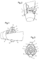
- Fig. 1
- in perspektivischer Darstellung ein an das Motorgehäuse eines Handmixers angekoppeltes Schaftteil,
- Fig. 2
- in perspektivischer Darstellung ein an das Motorgehäuse eines Handmixers angekoppeltes Schaftteil, in einer um 90° gegenüber der Darstellung in Fig. 1 gedrehten Darstellung,
- Fig. 3
- eine Draufsicht auf die Ankoppelseite des Motorgehäuses,
- Fig. 4
- die Ankoppelstelle eines Motorgehäuses und Schaftteiles im Längsschnitt,
- Fig. 5
- die Ankoppelstelle eines Motorgehäuses und Schaftteiles in einem gegenüber dem Längsschnitt nach Fig. 4 um 90° versetzten Längsschnitt.
Claims (12)
- Handmixer, mit einem einen Antriebsmotor enthaltendes Motorgehäuse (1), mit dem ein Schaftteil (2) lösbar verbunden ist, in welchem Schaftteil (2) die Welle eines Werkzeuges drehbar gelagert ist, die im an das Motorgehäuse (1) angekoppelten Zustand des Schaftteiles (2) drehfest mit der Welle des Antriebsmotors verbunden ist, wobei am Motorgehäuse (1) oder am Schaftteil (2) eine Haltenut (8) vorgesehen ist, in welche ein am Motorgehäuse (1) oder am Schaftteil (2) angeordnetes Halteelement (3) eingreift, auf das zumindest von einer Seite aus mittels einer Drucktaste (5) eine ein Aufspreizen des Halteelementes (3) bewirkende Druckkraft ausübbar ist, dadurch gekennzeichnet, dass das Halteelement (3) auf der der Angriffseite der Drucktaste (5) gegenüberliegenden Seite zumindest in Aufspreizrichtung ortsfest abgestützt ist.
- Handmixer nach Anspruch 1, dadurch gekennzeichnet, dass das Halteelement (3) mindestens einen ausbauchbaren Haltearm (4) aufweist, der wenigstens annähernd mit seinen Ausbauchungsbereichen in die Haltenut (8) eingreift.
- Handmixer nach Anspruch 1, dadurch gekennzeichnet, dass das Halteelement (3) zwei das Schafteil (2) umfassende, ausbauchbare Haltearme (4) aufweist, die in ihrem Ausbauchungsbereich jeweils mit ihrer Innenseite in die Haltenut (8) eingreifen.
- Handmixer nach Anspruch 2 oder 3, dadurch gekennzeichnet, dass an dem oder den Haltearmen(4) jeweils ein in die Haltenut (8) eingreifender, mit einer Anlaufschräge versehener Rastvorsprung (7) vorgesehen ist.
- Handmixer nach einem der vorhergehenden Ansprüche, dadurch gekennzeichnet, dass die Drucktaste (5) einteilig mit dem Halteelement (3) verbunden ist.
- Handmixer nach einem der Ansprüche 3-5, dadurch gekennzeichnet, dass die Haltearme (4) auf der der Angriffseite der Drucktaste (5) gegenüberliegenden Seite miteinander verbunden sind.
- Handmixer nach Anspruch 6, dadurch gekennzeichnet, dass die Haltearme (4) ein umfangsmäßig geschlossenes Oval bilden.
- Handmixer nach Anspruch 6, dadurch gekennzeichnet, dass die Haltearme (4) eine umfangsmäßig geschlossene Raute bilden.
- Handmixer nach Anspruch 7 oder 8, dadurch gekennzeichnet, dass das Halteelement (3) in Richtung seiner längeren Achse mit zwei gegenüberliegenden Drucktasten (5) versehen ist.
- Handmixer nach einem der vorhergehenden Ansprüche, dadurch gekennzeichnet, dass mindestens an einer Drucktaste (5) eine auf den Schafteil (2) wirkende Auswurfschräge (6) vorgesehen ist.
- Handmixer nach einem der vorhergehenden Ansprüche, dadurch gekennzeichnet, dass die Haltemut (8) am Schaftteil (8) angeordnet ist.
- Handmixer nach einem der vorhergehenden Ansprüche, dadurch gekennzeichnet, dass das Halteelement (3) mit seinen die einander gegenüberliegenden Drucktasten (5) verbindenden Haltearmen (4) einstückig aus Kunststoffspritzguss gefertigt ist.
Applications Claiming Priority (2)
| Application Number | Priority Date | Filing Date | Title |
|---|---|---|---|
| DE20006028U DE20006028U1 (de) | 2000-03-31 | 2000-03-31 | Handmixer |
| DE20006028U | 2000-03-31 |
Publications (3)
| Publication Number | Publication Date |
|---|---|
| EP1138239A2 true EP1138239A2 (de) | 2001-10-04 |
| EP1138239A3 EP1138239A3 (de) | 2002-05-29 |
| EP1138239B1 EP1138239B1 (de) | 2004-09-15 |
Family
ID=7939674
Family Applications (1)
| Application Number | Title | Priority Date | Filing Date |
|---|---|---|---|
| EP01101543A Expired - Lifetime EP1138239B1 (de) | 2000-03-31 | 2001-01-24 | Handmixer |
Country Status (6)
| Country | Link |
|---|---|
| EP (1) | EP1138239B1 (de) |
| AT (1) | ATE275857T1 (de) |
| DE (2) | DE20006028U1 (de) |
| DK (1) | DK1138239T3 (de) |
| ES (1) | ES2228668T3 (de) |
| PT (1) | PT1138239E (de) |
Cited By (2)
| Publication number | Priority date | Publication date | Assignee | Title |
|---|---|---|---|---|
| EP2193734A1 (de) * | 2008-12-05 | 2010-06-09 | Koninklijke Philips Electronics N.V. | Kupplungsanordnung, Küchengerät und Handmixer |
| US9392910B2 (en) | 2012-06-08 | 2016-07-19 | Koninklijke Philips N.V. | Interface for a handheld kitchen appliance |
Families Citing this family (7)
| Publication number | Priority date | Publication date | Assignee | Title |
|---|---|---|---|---|
| DE10022131C1 (de) * | 2000-05-06 | 2001-09-13 | Braun Gmbh | Kupplungsvorrichtung für eine Küchenmaschine |
| DE10114373A1 (de) | 2001-03-23 | 2002-10-10 | Braun Gmbh | Hand- oder Stabmixer mit Kupplungsvorrichtung |
| FR2854561B1 (fr) * | 2003-05-09 | 2006-06-02 | Dito Sama | Outil de machine de traitement de produits alimentaires ayant des moyens de verrouillage ameliores, et machine equipee d'un tel outil |
| DE102006030220B4 (de) * | 2006-06-30 | 2010-12-09 | BSH Bosch und Siemens Hausgeräte GmbH | Küchengerätesatz |
| CN101884503B (zh) * | 2009-05-11 | 2012-10-10 | 泓首翔电器(深圳)有限公司 | 一种手提搅拌机 |
| USD912460S1 (en) | 2019-10-25 | 2021-03-09 | Hamilton Beach Brands, Inc. | Hand blender |
| DE102020133500A1 (de) | 2020-12-15 | 2022-06-15 | Olympus Winter & Ibe Gmbh | Rastring, Schaft für ein chirurgisches Handgerät sowie chirurgisches Handgerät |
Citations (1)
| Publication number | Priority date | Publication date | Assignee | Title |
|---|---|---|---|---|
| EP0692215B1 (de) | 1994-07-12 | 1997-08-13 | Braun Aktiengesellschaft | Handmixer |
Family Cites Families (1)
| Publication number | Priority date | Publication date | Assignee | Title |
|---|---|---|---|---|
| FR1467108A (fr) * | 1965-12-02 | 1967-01-27 | Moulinex Sa | Mixer plongeant |
-
2000
- 2000-03-31 DE DE20006028U patent/DE20006028U1/de not_active Expired - Lifetime
-
2001
- 2001-01-24 AT AT01101543T patent/ATE275857T1/de not_active IP Right Cessation
- 2001-01-24 DK DK01101543T patent/DK1138239T3/da active
- 2001-01-24 ES ES01101543T patent/ES2228668T3/es not_active Expired - Lifetime
- 2001-01-24 DE DE50103585T patent/DE50103585D1/de not_active Expired - Lifetime
- 2001-01-24 EP EP01101543A patent/EP1138239B1/de not_active Expired - Lifetime
- 2001-01-24 PT PT01101543T patent/PT1138239E/pt unknown
Patent Citations (1)
| Publication number | Priority date | Publication date | Assignee | Title |
|---|---|---|---|---|
| EP0692215B1 (de) | 1994-07-12 | 1997-08-13 | Braun Aktiengesellschaft | Handmixer |
Cited By (2)
| Publication number | Priority date | Publication date | Assignee | Title |
|---|---|---|---|---|
| EP2193734A1 (de) * | 2008-12-05 | 2010-06-09 | Koninklijke Philips Electronics N.V. | Kupplungsanordnung, Küchengerät und Handmixer |
| US9392910B2 (en) | 2012-06-08 | 2016-07-19 | Koninklijke Philips N.V. | Interface for a handheld kitchen appliance |
Also Published As
| Publication number | Publication date |
|---|---|
| ES2228668T3 (es) | 2005-04-16 |
| ATE275857T1 (de) | 2004-10-15 |
| DE50103585D1 (de) | 2004-10-21 |
| EP1138239A3 (de) | 2002-05-29 |
| PT1138239E (pt) | 2004-12-31 |
| EP1138239B1 (de) | 2004-09-15 |
| DK1138239T3 (da) | 2005-01-24 |
| DE20006028U1 (de) | 2000-07-27 |
Similar Documents
| Publication | Publication Date | Title |
|---|---|---|
| DE4424501C1 (de) | Handmixer | |
| DE69718446T2 (de) | Haarschneidesystem mit einer haarschneidevorrichtung und einer kammvorrichtung, die an der haarschneidevorrichtung befestigt werden kann und die zwei federbelastete kammabschnitte hat | |
| DE60101761T2 (de) | Gegenlagerböckchen für Fahrzeugsonnenblenden | |
| DE19650204C2 (de) | Chirurgische Stanze | |
| EP1372447B1 (de) | Hand-oder stabmixer mit kupplungsvorrichtung | |
| DE1905352B2 (de) | Scheibenwischer, insbesondere fuer kraftfahrzeuge | |
| EP4019789B1 (de) | Möbelbeschlag | |
| DE20302694U1 (de) | Beschlag | |
| DE2610200A1 (de) | Beschlag zum loesbaren verbinden von bauteilen, insbesondere zum wieder loesbaren verbinden von plattenfoermigen bauteilen | |
| EP1138239A2 (de) | Handmixer | |
| DE2742021C2 (de) | ||
| DE102021126490B3 (de) | Handgriff mit einem Auswerfer für einen Nassrasierer | |
| DE202013105155U1 (de) | Haarschneider mit einem verriegelbaren Schneidkopf | |
| EP1466690B1 (de) | Säbelsäge mit Justiervorrichtung für eine Führungsvorrichtung | |
| EP0804698B1 (de) | Griff für eine sanitärarmatur | |
| EP1888280B1 (de) | Verbindung zwischen zwei werkzeugteilen | |
| DE4429063A1 (de) | Werkzeug mit Handgriff, insbesondere Haushaltsmesser | |
| DE3246887A1 (de) | Stielbefestigungskupplung, insbesondere fuer haus- und gartengeraete | |
| DE19940970B4 (de) | Vorrichtung zur Befestigung eines Handgriffes an einem Koch- oder Bratgefäß | |
| DE4240463A1 (en) | Coupling to extend switch actuation plunger - has in=line coupling with spring clip inserted for coupling to switch body | |
| DE3842850A1 (de) | Verbindungselement zur herstellung einer loesbaren verbindung zwischen wenigstens zwei teilen eines kraftfahrzeuges | |
| DE3615133C2 (de) | ||
| DE10137842B4 (de) | Bauteil zur Aufnahme in ein Karosserieteil, insbesondere Leuchte | |
| DE102010039454A1 (de) | Verschluss einer Befestigungsvorrichtung für ein Flächenelement einer Dunstabzugshaube und Dunstabzugshaube | |
| DE10316326A1 (de) | Befestigungsvorrichtung zur Befestigung eines Beschlagteiles |
Legal Events
| Date | Code | Title | Description |
|---|---|---|---|
| PUAI | Public reference made under article 153(3) epc to a published international application that has entered the european phase |
Free format text: ORIGINAL CODE: 0009012 |
|
| AK | Designated contracting states |
Kind code of ref document: A2 Designated state(s): AT BE CH CY DE DK ES FI FR GB GR IE IT LI LU MC NL PT SE TR |
|
| AX | Request for extension of the european patent |
Free format text: AL;LT;LV;MK;RO;SI |
|
| PUAL | Search report despatched |
Free format text: ORIGINAL CODE: 0009013 |
|
| AK | Designated contracting states |
Kind code of ref document: A3 Designated state(s): AT BE CH CY DE DK ES FI FR GB GR IE IT LI LU MC NL PT SE TR |
|
| AX | Request for extension of the european patent |
Free format text: AL;LT;LV;MK;RO;SI |
|
| 17P | Request for examination filed |
Effective date: 20021129 |
|
| AKX | Designation fees paid |
Designated state(s): AT BE CH CY DE DK ES FI FR GB GR IE IT LI LU MC NL PT SE TR |
|
| 17Q | First examination report despatched |
Effective date: 20030305 |
|
| RAP1 | Party data changed (applicant data changed or rights of an application transferred) |
Owner name: BSH BOSCH UND SIEMENS HAUSGERAETE GMBH |
|
| GRAP | Despatch of communication of intention to grant a patent |
Free format text: ORIGINAL CODE: EPIDOSNIGR1 |
|
| GRAS | Grant fee paid |
Free format text: ORIGINAL CODE: EPIDOSNIGR3 |
|
| GRAA | (expected) grant |
Free format text: ORIGINAL CODE: 0009210 |
|
| AK | Designated contracting states |
Kind code of ref document: B1 Designated state(s): AT BE CH CY DE DK ES FI FR GB GR IE IT LI LU MC NL PT SE TR |
|
| PG25 | Lapsed in a contracting state [announced via postgrant information from national office to epo] |
Ref country code: IE Free format text: LAPSE BECAUSE OF FAILURE TO SUBMIT A TRANSLATION OF THE DESCRIPTION OR TO PAY THE FEE WITHIN THE PRESCRIBED TIME-LIMIT Effective date: 20040915 Ref country code: FI Free format text: LAPSE BECAUSE OF FAILURE TO SUBMIT A TRANSLATION OF THE DESCRIPTION OR TO PAY THE FEE WITHIN THE PRESCRIBED TIME-LIMIT Effective date: 20040915 |
|
| REG | Reference to a national code |
Ref country code: GB Ref legal event code: FG4D Free format text: NOT ENGLISH Ref country code: CH Ref legal event code: EP |
|
| REG | Reference to a national code |
Ref country code: CH Ref legal event code: NV Representative=s name: SIEMENS SCHWEIZ AG |
|
| GBT | Gb: translation of ep patent filed (gb section 77(6)(a)/1977) |
Effective date: 20040917 |
|
| REG | Reference to a national code |
Ref country code: IE Ref legal event code: FG4D Free format text: GERMAN |
|
| REF | Corresponds to: |
Ref document number: 50103585 Country of ref document: DE Date of ref document: 20041021 Kind code of ref document: P |
|
| PG25 | Lapsed in a contracting state [announced via postgrant information from national office to epo] |
Ref country code: GR Free format text: LAPSE BECAUSE OF FAILURE TO SUBMIT A TRANSLATION OF THE DESCRIPTION OR TO PAY THE FEE WITHIN THE PRESCRIBED TIME-LIMIT Effective date: 20041215 |
|
| REG | Reference to a national code |
Ref country code: SE Ref legal event code: TRGR |
|
| REG | Reference to a national code |
Ref country code: PT Ref legal event code: SC4A Free format text: AVAILABILITY OF NATIONAL TRANSLATION Effective date: 20041018 |
|
| PG25 | Lapsed in a contracting state [announced via postgrant information from national office to epo] |
Ref country code: LU Free format text: LAPSE BECAUSE OF NON-PAYMENT OF DUE FEES Effective date: 20050124 Ref country code: CY Free format text: LAPSE BECAUSE OF FAILURE TO SUBMIT A TRANSLATION OF THE DESCRIPTION OR TO PAY THE FEE WITHIN THE PRESCRIBED TIME-LIMIT Effective date: 20050124 |
|
| REG | Reference to a national code |
Ref country code: DK Ref legal event code: T3 |
|
| PG25 | Lapsed in a contracting state [announced via postgrant information from national office to epo] |
Ref country code: MC Free format text: LAPSE BECAUSE OF NON-PAYMENT OF DUE FEES Effective date: 20050131 Ref country code: AT Free format text: LAPSE BECAUSE OF NON-PAYMENT OF DUE FEES Effective date: 20050131 |
|
| REG | Reference to a national code |
Ref country code: ES Ref legal event code: FG2A Ref document number: 2228668 Country of ref document: ES Kind code of ref document: T3 |
|
| REG | Reference to a national code |
Ref country code: IE Ref legal event code: FD4D |
|
| ET | Fr: translation filed | ||
| PLBE | No opposition filed within time limit |
Free format text: ORIGINAL CODE: 0009261 |
|
| STAA | Information on the status of an ep patent application or granted ep patent |
Free format text: STATUS: NO OPPOSITION FILED WITHIN TIME LIMIT |
|
| 26N | No opposition filed |
Effective date: 20050616 |
|
| REG | Reference to a national code |
Ref country code: CH Ref legal event code: PCAR Free format text: SIEMENS SCHWEIZ AG;INTELLECTUAL PROPERTY FREILAGERSTRASSE 40;8047 ZUERICH (CH) |
|
| REG | Reference to a national code |
Ref country code: FR Ref legal event code: PLFP Year of fee payment: 15 |
|
| REG | Reference to a national code |
Ref country code: CH Ref legal event code: PFA Owner name: BSH HAUSGERAETE GMBH, DE Free format text: FORMER OWNER: BSH BOSCH UND SIEMENS HAUSGERAETE GMBH, DE |
|
| REG | Reference to a national code |
Ref country code: ES Ref legal event code: PC2A Owner name: BSH HAUSGERATE GMBH Effective date: 20150527 |
|
| REG | Reference to a national code |
Ref country code: FR Ref legal event code: CD Owner name: BSH HAUSGERATE GMBH Effective date: 20151022 |
|
| REG | Reference to a national code |
Ref country code: FR Ref legal event code: PLFP Year of fee payment: 16 |
|
| REG | Reference to a national code |
Ref country code: FR Ref legal event code: PLFP Year of fee payment: 17 |
|
| REG | Reference to a national code |
Ref country code: FR Ref legal event code: PLFP Year of fee payment: 18 |
|
| PGFP | Annual fee paid to national office [announced via postgrant information from national office to epo] |
Ref country code: NL Payment date: 20180124 Year of fee payment: 18 |
|
| PGFP | Annual fee paid to national office [announced via postgrant information from national office to epo] |
Ref country code: CH Payment date: 20180125 Year of fee payment: 18 Ref country code: DK Payment date: 20180125 Year of fee payment: 18 |
|
| PGFP | Annual fee paid to national office [announced via postgrant information from national office to epo] |
Ref country code: BE Payment date: 20180124 Year of fee payment: 18 Ref country code: SE Payment date: 20180125 Year of fee payment: 18 Ref country code: PT Payment date: 20180114 Year of fee payment: 18 |
|
| REG | Reference to a national code |
Ref country code: DK Ref legal event code: EBP Effective date: 20190131 |
|
| REG | Reference to a national code |
Ref country code: CH Ref legal event code: PL |
|
| REG | Reference to a national code |
Ref country code: NL Ref legal event code: MM Effective date: 20190201 |
|
| REG | Reference to a national code |
Ref country code: BE Ref legal event code: MM Effective date: 20190131 |
|
| PG25 | Lapsed in a contracting state [announced via postgrant information from national office to epo] |
Ref country code: NL Free format text: LAPSE BECAUSE OF NON-PAYMENT OF DUE FEES Effective date: 20190201 Ref country code: PT Free format text: LAPSE BECAUSE OF NON-PAYMENT OF DUE FEES Effective date: 20190724 Ref country code: SE Free format text: LAPSE BECAUSE OF NON-PAYMENT OF DUE FEES Effective date: 20190125 |
|
| PG25 | Lapsed in a contracting state [announced via postgrant information from national office to epo] |
Ref country code: BE Free format text: LAPSE BECAUSE OF NON-PAYMENT OF DUE FEES Effective date: 20190131 |
|
| PG25 | Lapsed in a contracting state [announced via postgrant information from national office to epo] |
Ref country code: LI Free format text: LAPSE BECAUSE OF NON-PAYMENT OF DUE FEES Effective date: 20190131 Ref country code: CH Free format text: LAPSE BECAUSE OF NON-PAYMENT OF DUE FEES Effective date: 20190131 |
|
| PG25 | Lapsed in a contracting state [announced via postgrant information from national office to epo] |
Ref country code: DK Free format text: LAPSE BECAUSE OF NON-PAYMENT OF DUE FEES Effective date: 20190131 |
|
| PGFP | Annual fee paid to national office [announced via postgrant information from national office to epo] |
Ref country code: DE Payment date: 20200131 Year of fee payment: 20 Ref country code: GB Payment date: 20200127 Year of fee payment: 20 Ref country code: ES Payment date: 20200219 Year of fee payment: 20 Ref country code: IT Payment date: 20200122 Year of fee payment: 20 |
|
| PGFP | Annual fee paid to national office [announced via postgrant information from national office to epo] |
Ref country code: TR Payment date: 20200121 Year of fee payment: 20 Ref country code: FR Payment date: 20200123 Year of fee payment: 20 |
|
| REG | Reference to a national code |
Ref country code: DE Ref legal event code: R071 Ref document number: 50103585 Country of ref document: DE |
|
| REG | Reference to a national code |
Ref country code: GB Ref legal event code: PE20 Expiry date: 20210123 |
|
| PG25 | Lapsed in a contracting state [announced via postgrant information from national office to epo] |
Ref country code: GB Free format text: LAPSE BECAUSE OF EXPIRATION OF PROTECTION Effective date: 20210123 |
|
| REG | Reference to a national code |
Ref country code: ES Ref legal event code: FD2A Effective date: 20210430 |
|
| PG25 | Lapsed in a contracting state [announced via postgrant information from national office to epo] |
Ref country code: ES Free format text: LAPSE BECAUSE OF EXPIRATION OF PROTECTION Effective date: 20210125 |
|
| PG25 | Lapsed in a contracting state [announced via postgrant information from national office to epo] |
Ref country code: TR Free format text: LAPSE BECAUSE OF NON-PAYMENT OF DUE FEES Effective date: 20210124 |