EP3256293B1 - Système robotique - Google Patents
Système robotique Download PDFInfo
- Publication number
- EP3256293B1 EP3256293B1 EP16703433.9A EP16703433A EP3256293B1 EP 3256293 B1 EP3256293 B1 EP 3256293B1 EP 16703433 A EP16703433 A EP 16703433A EP 3256293 B1 EP3256293 B1 EP 3256293B1
- Authority
- EP
- European Patent Office
- Prior art keywords
- adapter
- cable
- application part
- robot
- electrical connection
- Prior art date
- Legal status (The legal status is an assumption and is not a legal conclusion. Google has not performed a legal analysis and makes no representation as to the accuracy of the status listed.)
- Active
Links
Images


Classifications
-
- B—PERFORMING OPERATIONS; TRANSPORTING
- B25—HAND TOOLS; PORTABLE POWER-DRIVEN TOOLS; MANIPULATORS
- B25J—MANIPULATORS; CHAMBERS PROVIDED WITH MANIPULATION DEVICES
- B25J19/00—Accessories fitted to manipulators, e.g. for monitoring, for viewing; Safety devices combined with or specially adapted for use in connection with manipulators
- B25J19/0025—Means for supplying energy to the end effector
- B25J19/0029—Means for supplying energy to the end effector arranged within the different robot elements
-
- B—PERFORMING OPERATIONS; TRANSPORTING
- B25—HAND TOOLS; PORTABLE POWER-DRIVEN TOOLS; MANIPULATORS
- B25J—MANIPULATORS; CHAMBERS PROVIDED WITH MANIPULATION DEVICES
- B25J9/00—Program-controlled manipulators
- B25J9/0009—Constructional details, e.g. manipulator supports, bases
Definitions
- the present disclosure relates to a robot system and a method of manufacturing such a robot system, and a use of such a robot system.
- end-effectors of robots are not purchased from the manufacturer of the robot, but are made, for example, in the user's company or by specialized suppliers.
- the robot manufacturer often does not know which functionalities should be provided with the aid of the robot. Therefore, the robot manufacturer usually provides on or in the robot an attachment device for the end effector as well as signal and / or power supply lines which are used to drive the end effector.
- the US 2015/0004837 A1 discloses an electromechanical connection system for a medical device according to the preamble of claim 1.
- An object of an embodiment of the present invention is to provide an improved robotic system, which in particular allows to simplify the robot manufacturing and / or the retrofitting of the robot system from one to the other application.
- Claim 11 protects the use of a robotic system described herein, claims 12 and 13, of methods of making a robotic system described herein.
- Advantageous embodiments of the invention are the subject of the dependent claims.
- a robot system comprises: (i) a robot for guiding an application part, wherein the robot has a robot arm having a base, a base proximal portion, a base distal portion, and a fastening device for attachment, in particular detachable the application part, wherein the fastening device is arranged in the distal region, a grounding and a cable for, in particular releasable, connection with the application part and a control device with at least one signal line and / or at least one power supply line, a protective conductor, a distal connecting means for electrical, in particular detachable, connection of the application part with the cable and a proximal connection means for electrical, in particular detachable, connection of the control device with the cable; and (II) an adapter, comprising an electrical line for electrical, in particular releasable, connection of the protective conductor of the cable to the ground of the robot.
- the robot is an articulated arm robot having a plurality of axles, in particular at least five, six or seven axles.
- This robot design has the advantage in one embodiment that robots of this type can act in a small space. This is particularly important when robots need to work together with other machines or people in a limited space, such as in the field of medicine, in particular surgery, where several robots and / or a robot and several people work around an operating table.
- these articulated arm robots require only a very small mounting surface, which allows them to be attached to the floor, wall, ceiling or rail system on the floor, wall or ceiling.
- a proximal and a distal region of the robot arm is defined.
- the proximal area is the lower area of the robotic arm, ie the area near the base or floor.
- the distal region is the region at the upper end of the robotic arm seen in such a way, where as a rule the application part or at least one fastening device for fastening an application part is provided.
- the application part may be any type of manipulator and / or sensor.
- the application part may be a gripper, a lifting element, a support element, a joining device, a separating device, a sensor device and in particular a medical device.
- These include, in particular, application parts for minimally invasive surgery or for open heart surgery, such as scissors, cameras, probes, knives, staplers, or wound closure devices, defibrillators, lasers, suction devices, grippers, and the like.
- the application part is in particular an electrical, in particular electronic, device which can be connected to a control device, in particular is connected and is supplyable by it with commands and / or energy, in particular is or is supplied and / or this data, in particular measurement or video data, transmits or is furnished or provided for this purpose.
- the application part is held, in particular mechanically, via the fastening device in the distal region of the robot arm and guided by it.
- the connection between the fastening device and the application part can be made detachable or non-detachable.
- the application part is in particular a separately produced component, which in a further development is not controlled by a robot controller. Frequently, the manufacturer of the robot systems, the later applications are not known. Therefore, according to one embodiment, the application part has a control unit independent of the robot control, the two latter being addressed jointly by an operator only in the context of the man-machine interface, which is provided in particular by the manufacturers of the application parts.
- the earthing refers to an electrically conductive connection of the robot system to the ground or to a potential which, at least substantially, corresponds to that of the ground.
- the aim is in particular to provide a reference potential, which can be used as a reference as needed on the one hand, and on the other to avoid the static charge of the robot and to provide a protection mechanism in the event of a malfunction of the current in the robot.
- the housing of the robot is grounded to avoid that a surrounding operator and / or in the case of medical technology, a patient gets an electric shock.
- This grounding is usually very useful for the robot in normal operation, in order to safely dissipate uncontrolled current flows due to static charge.
- the grounding is part of the robot, in particular of the robot arm.
- the manufacturer of the robot often does not know for which application the robot provided by him is ultimately to be used. Therefore, a cable is provided on or in the robot, which allows the manufacturer of the application part, the supply and / or control and / or data evaluation, and which is not used in one embodiment of the other components of the robot.
- the application part is connected to the control unit via at least one signal line and / or at least one power line with the cable.
- the term line says nothing here about the nature, number and design of the respective veins provided.
- a line can thus contain one, two, three or more wires.
- the cores may comprise copper, aluminum or other current-carrying metals and / or alloys, but also glass and / or plastic materials, for example to transmit light waves.
- the application part After execution, the application part is powered by the cable only with energy, while the data transfer is wireless.
- only a data transfer takes place via the cable with the application part, while the application part has its own energy source, in particular a battery, or a separate energy connection.
- the cable has a protective conductor, which in one embodiment is designed in the form of a shield surrounding the internal signal and / or power supply lines.
- this shield has a metal-containing film and / or a mesh of metal-containing wire, which or which receives the signal and / or power supply lines in order to avoid interference in the form of electromagnetic fields, as for example in the vicinity of electric motors, as they are also used in particular for moving the robot arm to shield.
- the cable is provided according to an embodiment, at least at its ends with connecting means.
- the cable has a proximal connection means in the vicinity of the base and a distal connection means in the vicinity of the attachment means for mechanically fixing the application part to the robot arm.
- the proximal connection means can be electrically conductively connected to the control unit, in particular connected, and / or the distal connection means can be electrically conductively connected, in particular connected, to the application part.
- connection of the proximal connection means with the control unit and / or the connection of the distal Lanyard detachable with the application part. This is advantageous for adapting the robot system to different tasks during its service life.
- the robot system has, in addition to the robot, an adapter which connects the protective conductor of the cable to the grounding of the robot or is provided or set up for this purpose.
- an adapter which connects the protective conductor of the cable to the grounding of the robot or is provided or set up for this purpose.
- the protective conductor of the cable is connected to the grounding of the robot, in particular short-circuited, so as to pull the protective conductor to the grounding potential of the robot. This creates a closed electrical circuit across the earth between the application part and the environment, as it is advantageous for some applications.
- the earthing is effected via a contact of the protective conductor with a grounded housing part of the robot or via a separate grounding line, which runs in one embodiment within the robot arm.
- the latter configuration is particularly preferred when in normal operation large currents are expected via the ground, because then the housing of the robot remains de-energized and there is no significant risk of electric shock to the user and / or the patient.
- the protective conductor is not earthed unless it is in electrically conductive contact with the adapter.
- the adapterless protective conductor is not earthed. If the adapter is not electrically connected to the protective conductor of the cable and the grounding of the robot, then in this embodiment, the protective conductor itself is not grounded. It is at a different energy level than the ground potential and there is no significant electrically conductive connection with the earth. This means that a non-separately grounded, attached to this protective conductor application part is also not grounded. Due to insulation resistance across the earth, no significant circuit can be closed here, which is why this state is also referred to as "floating".
- the proximal and / or distal connecting means has at least one plug and / or at least one socket.
- the proximal and / or distal connecting means may have any plug and / or socket configuration or combination.
- centering elements are provided, which facilitate the insertion of a connecting medium counterpart of the application part and / or the control unit. These centering elements can be provided on the connecting means and / or on the connecting medium counterpart.
- the connecting means and / or the connecting means counterpart on a rotation protection which substantially excludes a false contact.
- the connecting means and / or the connecting means counterpart holding means such as barbs, to prevent accidental disconnection.
- the robotic arm has securing means for preventing unauthorized loosening and / or securing of the adapter.
- the robot system has the application part, which is attached to the fastening device of the robot arm, in particular releasably, and is connected via the distal connecting means to the cable, in particular detachably connected, wherein the adapter between the distal connecting means and the application part is arranged or is integrally disposed in the application part.
- the adapter is arranged as a separate element between the cable and the application part. This has the advantage that the adapter is ready for several usable application parts and can be flexibly installed and removed again.
- the adapter is arranged integrally in the application part. This has the advantage that a so designed application part in one Version can not be used ungrounded and thus provides optimum protection against the erroneous ungrounded use of the application part.
- the robot system has the control unit for controlling and / or reading and / or powering the application part, the control unit being connectable, in particular connected, to the cable via the proximal connection means and the adapter being connected between the proximal connection means and the Control unit is arranged or is or is arranged integrally in the control unit.
- the adapter is or is arranged as a separate element between the cable and the control unit. This has the advantage that the adapter is available for several usable control units and can be flexibly installed and removed again.
- the adapter is integrally arranged in the control unit. This has the advantage that such a designed control unit can not be used ungrounded, thus enabling optimum protection against the erroneous ungrounded use of the application part.
- the at least one signal line is set up to transmit data based on the IEEE 802.3 Ethernet standard.
- the at least one power supply line is arranged to provide an electrical voltage at the application part of up to 60V.
- the transmitted electrical power may be based on a DC voltage or on an AC voltage.
- a direct current or an alternating current is transmitted via the at least one energy supply line or the energy supply line is provided or set up for this purpose.
- the transmission of DC is advantageous because many application parts require DC and thus on a corresponding rectifier can be dispensed with in the application part, which is usually required when alternating current is transmitted.
- On the other hand speaks for the use of alternating current that this can be generated comparatively easily with a conventional generator, since a sinusoidal course of the current curve is the natural consequence of a circular motion of the generator.
- the cable extends at least substantially within the robot arm.
- the cable may run either partially or completely inside the robot arm.
- a robot arm which has at least one completely or partially free-running cable less, which leads to a significant improvement in the safety and mobility of the robot arm. Furthermore, the cleaning of the robot arm, in particular in a sterile environment such as an operating room, is facilitated since the cleaning is not impeded or even prevented by the cable running at least substantially inside the robot arm.
- Another possible advantage of this embodiment is that the force effect of the cable on the robot arm and thus on the movement of the robot arm in a force-controlled mode can be taken into account more easily and / or more easily.
- the robot is electrically insulated from the application part by insulation, in particular by a plastic plate, and / or the robot is electrically insulated from the cable, in particular by insulation, in particular by a plastic plate.
- the adapter has, on a first side, first connection means which are complementary to the proximal connection means of the cable, the adapter having on a second side second connection means which are complementary to connection means of the control unit or the adapter on a first side, first connection means, which are complementary to connection means of the application part, the adapter having, on a second side, second connection means, which are complementary to the distal connection means of the cable.
- the proximal connection means of the cable correspond to the connection means of the control unit in a complementary manner, with the result that the control unit can be connected both with and without adapter to the cable, without requiring a further connection means.
- the distal connection means of the cable correspond to the connection means of the application part in a complementary manner, with the result that the application part can be connected to the cable both with and without adapters, without requiring any further connection means.
- the robot system described here is used, wherein the application part is a medical treatment device for treating a patient, in particular with electrical energy, and / or is a medical diagnostic device, in particular for, in particular electrical, acquisition of data at least a body function of the patient.
- the robotic system having the robot and the adapter is particularly advantageous because in one embodiment a possibility is provided for both grounded protective conductor and non-grounded protective conductor applications with a single robot without significant retrofitting on or in the robot realize.
- the adapter of step (a) or of step (b) is formed integrally in the control unit or the adapter according to step (a ') or according to step (b') is integrally formed in the application part.
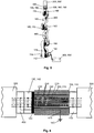
- the Figures 1 and 2 show a first embodiment of a robot system of the present invention, wherein an adapter 400 is not connected to the robot 100.
- the robot 100 has a robot arm 110 in the form of a multi-axis robot arm and a robot controller (not shown).
- the robot 100 is attached to its base 112 on the floor or to a rail system (not shown).
- a proximal connection means 150 for connecting a cable 200 arranged in the robot arm 110 to a control device 500 is provided in the proximal region 114 adjacent to the base.
- the control unit 500 also includes the cable which connects the control unit 500 with the robot arm 110 directly or indirectly, in particular via the adapter 400.
- the robot arm 110 includes a rotary device 170 and a plurality of Hinges 160 which are moved in particular via electromotive drives (not shown).
- a proximal portion 114 opposite distal portion 116 has a fastening device 130 for mechanical attachment of an application part 300, a distal connection means 130 for electrically connecting the cable 200 with the application part 300, an insulation 120 in the form of a plastic plate and a securing means 190 for securing the application part 300 against unauthorized (dis) assembly of the application part 300.
- the cable 200 which in detail in Fig. 7 is shown, has a plurality of signal lines 250 and a plurality of power supply lines 240, which in particular each have a separate insulation (not shown) with respect to the other lines.
- the lines 240, 250 are surrounded by a protective conductor 230, which shields them against electromagnetic interference fields, such as those generated by the electric motors within the robot arm.
- the protective conductor 230 may be formed in the form of a metal or metal alloy-containing film and / or a metal or metal alloy-containing wire mesh. To protect against a direct electrical energy transfer between robot arm 110 and cable 200, the latter additionally has an insulating layer 220 surrounding the protective conductor.
- the cable 200 further comprises a cable sheath 210, which is provided around the insulating layer 220 around.
- Insulation layer 220 and cable sheath 210 are preferably made of plastic, in particular of thermoplastic material.
- the tasks of the cable sheath 210 and the insulation layer are inherited from a common layer (not shown).
- the robot 100 or the robot arm 110 has a ground 180.
- This grounding may be in the form of an electrically conductive connection of the robot housing with the ground or by a separate grounded line, which is arranged in particular at least substantially in the interior of the robot arm 110.
- the cable 200 extends completely inside the robot arm 110. At the distal end of the cable 200, the distal connection means 140 is electrically connected and at the proximal end of the cable 200, the proximal connection means 150 is electrically connected. Care is taken in the connection that no electrically conductive connection between the robot 100 and the cable 200 is generated.
- the cable 200 is connected to the control unit 500.
- the cable 200 With connected to the application part 300.
- the protective conductor or shield 230 which is connected to the application part 300 via the distal connection means 140 after the first embodiment and is connected to the control device 500 via the proximal application means 150, but is not connected to the grounding 180, the protective conductor is not at the potential of the ground 180, so that the robot system is operated in the so-called floating mode.
- the second embodiment according to the FIGS. 3 and 4 differs from the first embodiment constructively essentially in that the adapter 400 between the proximal connection means 150 and the control unit 500 is electrically connected in between. All statements made above in relation to the first embodiment are also true for the second embodiment, should the text of the following paragraph or the knowledge of the skilled person not otherwise.
- the cable 200 is connected to the control unit 500.
- the protective conductor or the shielding 230 which is connected to the application part 300 via the distal connection means 140 according to the second embodiment and is connected via the proximal application means 150 to the control device 500 and via the adapter 400 and the robot arm 110 the ground 180 is connected, the protective conductor is at the potential of the ground 180, so that the application part is operated in the so-called grounded mode.
- the adapter 400 can be embodied as an integral component of the control device 500, which is either arranged in a complementary connection means of the control device 500 that is complementary to the proximal connection means 150 or is arranged in the control device 500 itself.
- the third embodiment according to the FIGS. 5 and 6 differs from the first embodiment constructively essentially in that the adapter 400 between the distal connection means 140 and the application part 300 is electrically connected in between. All statements made above in relation to the first embodiment are also true for the third embodiment, should the text of the following paragraph or the knowledge of the skilled person not otherwise.
- the cable 200 is connected to the application part 300.
- the protective conductor or the shielding 230 which is connected to the application part 300 via the distal connection means 140 according to the third embodiment and is connected via the proximal application means 150 to the control device 500 and via the adapter 400 and the robot arm 110 the ground 180 is connected, the protective conductor is at ground potential 180, so that the application part is operated in the so-called grounded mode.
- the adapter 400 may, in particular, be formed as an integral component of the application part 300, which is either arranged in a complementary connection means of the application part 300 that is complementary to the distal connection means 140 or is arranged in the application part 300 itself.
Landscapes
- Engineering & Computer Science (AREA)
- Robotics (AREA)
- Mechanical Engineering (AREA)
- Manipulator (AREA)
Claims (15)
- Système robot avec :(I) un robot (100) pour le guidage d'une partie d'application (300), dans lequel le robot (100) présente ;(a) un bras de robot (100) avec
une base (112) ;
une zone proximale (114) par rapport à la base (112) ;
une zone distale (116) par rapport à la base (112) ; et
un dispositif de fixation (130) pour la fixation, en particulier amovible, de la partie d'application (300), dans lequel le dispositif de fixation (130) est agencé dans la zone distale (116) ;(b) une terre (180) ; et(c) un câble (200) pour la liaison, en particulier amovible, à la partie d'application (300) et un appareil de commande (500), avec
au moins une ligne de signal (250) et/ou au moins une ligne d'alimentation en énergie (240) ;
un conducteur de protection (230) ;
un moyen de liaison distal (140) pour la liaison électrique, en particulier amovible, de la partie d'application (300) au câble (200) ; et
un moyen de liaison proximal (150) pour la liaison électrique, en particulier amovible, de l'appareil de commande (500) au câble (200) ; et(II) un adaptateur (400), caractérisé en ce que l'adaptateur (400) présente une ligne électrique (410) pour la liaison électrique, en particulier amovible, du conducteur de protection (230) du câble (200) à la terre (180) du robot (100). - Système robot selon la revendication 1, dans lequel le conducteur de protection (230) n'est pas mis à la terre, s'il n'est pas en contact électriquement conducteur avec l'adaptateur (400).
- Système robot selon l'une quelconque des revendications précédentes, dans lequel le moyen de liaison proximal et/ou le moyen de liaison distal (140, 150) présente au moins une fiche et/ou au moins une douille.
- Système robot selon l'une quelconque des revendications précédentes, dans lequel le bras de robot (110) présente en outre un moyen de blocage (190) pour empêcher un détachement et/ou une fixation non autorisé de l'adaptateur (400).
- Système robot selon l'une quelconque des revendications précédentes, présentant la partie d'application (300), laquelle est fixée, en particulier de manière amovible, au niveau du dispositif de fixation (130) du bras de robot (110) et est reliée, en particulier de manière amovible, au câble (200) par le biais du moyen de liaison distal (140), dans lequel l'adaptateur (400)(a) est agencé entre le moyen de liaison distal (140) et la partie d'application (300) ; ou(b) est agencé d'un seul tenant dans la partie d'application (300).
- Système robot selon l'une quelconque des revendications 1 à 4, présentant l'appareil de commande (500) pour la commande et/ou la lecture et/ou l'alimentation en énergie de la partie d'application (300), dans lequel l'appareil de commande (500) est relié au câble (200) par le biais du moyen de la liaison proximal (150) et dans lequel l'adaptateur (400)(a) est agencé entre le moyen de liaison proximal (150) et l'appareil de commande (500) ; ou(b) est agencé d'un seul tenant dans l'appareil de commande (500).
- Système robot selon l'une quelconque des revendications précédentes, dans lequel l'au moins une ligne de signal (250) est aménagée pour transmettre des données sur la base du standard Ethernet IEEE 802.3,
et/ou
dans lequel l'au moins une ligne d'alimentation en énergie (240) est aménagée pour mettre à disposition une tension électrique au niveau de la partie d'application (300) de jusqu'à 60 V. - Système robot selon l'une quelconque des revendications précédentes, dans lequel le câble (200) s'étend au moins sensiblement à l'intérieur du bras de robot (110).
- Système robot selon l'une quelconque des revendications précédentes, dans lequel le robot (100) est isolé électriquement de la partie d'application (300) par une isolation (120), en particulier par une plaque en plastique, et/ou dans lequel le robot (100) est isolé électriquement du câble (200).
- Système robot selon l'une quelconque des revendications précédentes, dans lequel l'adaptateur (400) présente sur un premier côté des premiers moyens de liaison, lesquels sont complémentaires aux moyens de liaison proximaux (150) du câble (200), et dans lequel l'adaptateur (400) présente sur un deuxième côté des deuxièmes moyens de liaison, lesquels sont complémentaires aux moyens de liaison de l'appareil de commande (500) ; ou
dans lequel l'adaptateur (400) présente sur un premier côté des premiers moyens de liaison, lesquels sont complémentaires à des moyens de liaison de la partie d'application (300), et
dans lequel l'adaptateur (400) présente sur un deuxième côté des deuxièmes moyens de liaison, lesquels sont complémentaires aux moyens de liaison distaux (140) du câble (200). - Utilisation d'un système robot selon l'une quelconque des revendications précédentes, dans lequel la partie d'application (300) est un appareil de traitement médical pour le traitement d'un patient, en particulier avec de l'énergie électrique, et/ou est un appareil de diagnostic médical, en particulier pour la détection de données relatives à au moins une fonction corporelle du patient.
- Procédé de fabrication d'un système robot selon l'une quelconque des revendications 1 à 10, présentant :(a) l'établissement d'une liaison électrique, en particulier amovible, entre l'adaptateur (400) et le câble (200) par le biais du moyen de liaison proximal (150) et l'établissement d'une liaison électrique, en particulier amovible, entre l'adaptateur (400) et l'appareil de commande (500) ; ou(a') l'établissement d'une liaison électrique, en particulier amovible, entre l'adaptateur (400) et le câble (200) par le biais du moyen de liaison distal (140) et l'établissement d'une liaison électrique, en particulier amovible, entre l'adaptateur (400) et la partie d'application (300).
- Procédé, en particulier selon la revendication 12, pour la fabrication d'un système robot selon l'une quelconque des revendications 1 à 10, présentant :(b) la séparation d'une liaison électrique, en particulier amovible, entre l'adaptateur (400) et le câble (200) et en particulier la séparation d'une liaison électrique, en particulier amovible, entre l'adaptateur (400) et l'appareil de commande (500) ; ou(b') la séparation d'une liaison électrique, en particulier amovible, entre l'adaptateur (400) et le câble (200) et en particulier la séparation d'une liaison électrique, en particulier amovible, entre l'adaptateur (400) et la partie d'application (300).
- Procédé selon la revendication 13, présentant en outre :(c) l'établissement d'une liaison électrique, en particulier amovible, entre un autre appareil de commande (500') et le câble (200), en particulier par le biais de l'adaptateur (400) ; ou(c') l'établissement d'une liaison électrique, en particulier amovible, entre une autre partie d'application (300') et le câble (200), en particulier par le biais de l'adaptateur (400).
- Procédé selon l'une quelconque des revendications de procédé précédentes, dans lequel l'adaptateur (400) est réalisé selon la revendication 12, étape (a) ou selon la revendication 13, étape (b), d'un seul tenant dans l'appareil de commande (500) ou dans lequel l'adaptateur (400) est réalisé selon la revendication 12, étape (a'), ou selon la revendication 13, étape (b'), d'un seul tenant dans la partie d'application (300).
Applications Claiming Priority (2)
| Application Number | Priority Date | Filing Date | Title |
|---|---|---|---|
| DE102015001624.5A DE102015001624A1 (de) | 2015-02-09 | 2015-02-09 | Robotersystem |
| PCT/EP2016/000190 WO2016128124A1 (fr) | 2015-02-09 | 2016-02-04 | Système robotique |
Publications (2)
| Publication Number | Publication Date |
|---|---|
| EP3256293A1 EP3256293A1 (fr) | 2017-12-20 |
| EP3256293B1 true EP3256293B1 (fr) | 2019-08-21 |
Family
ID=55315381
Family Applications (1)
| Application Number | Title | Priority Date | Filing Date |
|---|---|---|---|
| EP16703433.9A Active EP3256293B1 (fr) | 2015-02-09 | 2016-02-04 | Système robotique |
Country Status (5)
| Country | Link |
|---|---|
| US (1) | US20180029239A1 (fr) |
| EP (1) | EP3256293B1 (fr) |
| CN (1) | CN107206600B (fr) |
| DE (1) | DE102015001624A1 (fr) |
| WO (1) | WO2016128124A1 (fr) |
Families Citing this family (4)
| Publication number | Priority date | Publication date | Assignee | Title |
|---|---|---|---|---|
| DE102018205489B4 (de) * | 2018-04-11 | 2021-08-19 | Deutsches Zentrum für Luft- und Raumfahrt e.V. | Endeffektorbefestigungsvorrichtung |
| CN108927824A (zh) * | 2018-08-18 | 2018-12-04 | 卿茂荣 | 一种关节机器人手腕过线机构 |
| JP6806124B2 (ja) * | 2018-11-16 | 2021-01-06 | 株式会社安川電機 | ロボット |
| US12103167B2 (en) | 2019-07-17 | 2024-10-01 | Abb Schweiz Ag | Robot arm link with embedded cables and robot |
Family Cites Families (14)
| Publication number | Priority date | Publication date | Assignee | Title |
|---|---|---|---|---|
| US5556370A (en) * | 1993-07-28 | 1996-09-17 | The Board Of Trustees Of The Leland Stanford Junior University | Electrically activated multi-jointed manipulator |
| GB2397234A (en) * | 2003-01-20 | 2004-07-21 | Armstrong Healthcare Ltd | A tool holder arrangement |
| US8463439B2 (en) * | 2009-03-31 | 2013-06-11 | Intuitive Surgical Operations, Inc. | Optic fiber connection for a force sensing instrument |
| US9586327B2 (en) * | 2005-12-20 | 2017-03-07 | Intuitive Surgical Operations, Inc. | Hook and pivot electro-mechanical interface for robotic medical arms |
| US7762825B2 (en) * | 2005-12-20 | 2010-07-27 | Intuitive Surgical Operations, Inc. | Electro-mechanical interfaces to mount robotic surgical arms |
| US8052621B2 (en) * | 2006-02-22 | 2011-11-08 | Hansen Medical, Inc. | Method of sensing forces on a working instrument |
| DE102007046396A1 (de) * | 2007-09-21 | 2009-04-09 | Haug Gmbh & Co. Kg. | Luftionisationsgerät |
| DE102009028190A1 (de) * | 2009-08-03 | 2011-02-10 | Leibniz-Institut für Plasmaforschung und Technologie e.V. | Vorrichtung zur Erzeugung eines nichtthermischen Atmosphärendruck-Plasmas |
| JP5733964B2 (ja) * | 2009-12-24 | 2015-06-10 | キヤノン株式会社 | 高分子アクチュエータ |
| DE102010011643B4 (de) * | 2010-03-16 | 2024-05-29 | Christian Buske | Vorrichtung und Verfahren zur Plasmabehandlung von lebendem Gewebe |
| DE202012100384U1 (de) * | 2012-02-06 | 2013-05-10 | Kuka Systems Gmbh | Kupplungseinrichtung |
| US11284803B2 (en) * | 2012-11-15 | 2022-03-29 | Intuitive Surgical Operations, Inc. | Low capacitance endoscopic system |
| US9254170B2 (en) * | 2013-03-13 | 2016-02-09 | Ethicon Endo-Surgery, Inc. | Electrosurgical device with disposable shaft having modular subassembly |
| US9583896B2 (en) * | 2013-06-26 | 2017-02-28 | Intuitive Surgical Operations, Inc | Connector for medical device |
-
2015
- 2015-02-09 DE DE102015001624.5A patent/DE102015001624A1/de not_active Ceased
-
2016
- 2016-02-04 US US15/549,414 patent/US20180029239A1/en not_active Abandoned
- 2016-02-04 CN CN201680009401.0A patent/CN107206600B/zh active Active
- 2016-02-04 WO PCT/EP2016/000190 patent/WO2016128124A1/fr not_active Ceased
- 2016-02-04 EP EP16703433.9A patent/EP3256293B1/fr active Active
Non-Patent Citations (1)
| Title |
|---|
| None * |
Also Published As
| Publication number | Publication date |
|---|---|
| DE102015001624A1 (de) | 2016-08-11 |
| US20180029239A1 (en) | 2018-02-01 |
| WO2016128124A1 (fr) | 2016-08-18 |
| CN107206600A (zh) | 2017-09-26 |
| EP3256293A1 (fr) | 2017-12-20 |
| CN107206600B (zh) | 2020-10-13 |
Similar Documents
| Publication | Publication Date | Title |
|---|---|---|
| DE2803275C3 (de) | Fernschalteinrichtung zum Schalten eines monopolaren HF-Chirurgiegerätes | |
| EP3256293B1 (fr) | Système robotique | |
| EP3681755B1 (fr) | Dispositif de connexion de vehicule, unite de contact de plancher, systeme d'attelage de vehicule et procede de connexion conductive automatique d'une unite de contact de vehicule a une unite de contact de plancher | |
| DE102020125882A1 (de) | Abdeckungsanordnung für elektrische sammelschienenverbindung | |
| EP3390258B1 (fr) | Cabine d'ascenseur comprenant une balustrade repliable et dispositif de commande pour ascenseur comprenant une telle cabine d'ascenseur | |
| EP2481129B1 (fr) | Système d'accouplement mâle/femelle | |
| DE102013011681A1 (de) | Nabelgliedanordnung eines Industrieroboters mit hohlem Glied | |
| EP2151908B1 (fr) | Machine dynamoélectrique dotée d'un boîtier de connexion en plusieurs parties | |
| DE1765579B1 (de) | Anordnung zur halterung stromzufuehrung und kuehlung von elektrischen schaltungseinheiten | |
| WO2007113117A1 (fr) | Dispositif enfichable destine a assurer le contact du module a haute tension d'un vehicule hybride et module a haute tension pour vehicule hybride | |
| WO2017080797A1 (fr) | Batterie haute tension pour véhicule automobile et véhicule automobile | |
| EP2851909B1 (fr) | Système d'entraînement avec commande combinée du frein et du capteur | |
| DE102017010773B4 (de) | Leitungsbahnstruktur eines Roboters | |
| DE102019209854B4 (de) | Fahrzeugbordnetz | |
| EP2135333B1 (fr) | Câble de rallonge pour dispositifs d'usinage de tubes | |
| DE102019209654A1 (de) | Fahrzeugbordnetz | |
| EP3984118B1 (fr) | Entraînement linéaire antiparasité | |
| EP4344926B1 (fr) | Machine de travail dotée d'un entraînement électrique | |
| EP4171430B1 (fr) | Séparation électromécanique stérile | |
| DE112005003686T5 (de) | Intelligente Stromüberwachungseinheit | |
| DE102010062065A1 (de) | Modulares Elektronikgerät | |
| DE102014208924B4 (de) | Patientenliege | |
| DE102011052213A1 (de) | Kontakteinsetzanordnung | |
| DE102021109348A1 (de) | Ladekabel mit Sollbruchstelle | |
| DE102016117586A1 (de) | Explosionsgeschütztes Flurförderzeug |
Legal Events
| Date | Code | Title | Description |
|---|---|---|---|
| STAA | Information on the status of an ep patent application or granted ep patent |
Free format text: STATUS: THE INTERNATIONAL PUBLICATION HAS BEEN MADE |
|
| PUAI | Public reference made under article 153(3) epc to a published international application that has entered the european phase |
Free format text: ORIGINAL CODE: 0009012 |
|
| STAA | Information on the status of an ep patent application or granted ep patent |
Free format text: STATUS: REQUEST FOR EXAMINATION WAS MADE |
|
| 17P | Request for examination filed |
Effective date: 20170731 |
|
| AK | Designated contracting states |
Kind code of ref document: A1 Designated state(s): AL AT BE BG CH CY CZ DE DK EE ES FI FR GB GR HR HU IE IS IT LI LT LU LV MC MK MT NL NO PL PT RO RS SE SI SK SM TR |
|
| AX | Request for extension of the european patent |
Extension state: BA ME |
|
| DAV | Request for validation of the european patent (deleted) | ||
| DAX | Request for extension of the european patent (deleted) | ||
| RAP1 | Party data changed (applicant data changed or rights of an application transferred) |
Owner name: KUKA DEUTSCHLAND GMBH |
|
| GRAP | Despatch of communication of intention to grant a patent |
Free format text: ORIGINAL CODE: EPIDOSNIGR1 |
|
| STAA | Information on the status of an ep patent application or granted ep patent |
Free format text: STATUS: GRANT OF PATENT IS INTENDED |
|
| INTG | Intention to grant announced |
Effective date: 20190410 |
|
| RIN1 | Information on inventor provided before grant (corrected) |
Inventor name: VON TIESENHAUSEN, CYRILL Inventor name: FODOR, ROBERT |
|
| GRAS | Grant fee paid |
Free format text: ORIGINAL CODE: EPIDOSNIGR3 |
|
| GRAA | (expected) grant |
Free format text: ORIGINAL CODE: 0009210 |
|
| STAA | Information on the status of an ep patent application or granted ep patent |
Free format text: STATUS: THE PATENT HAS BEEN GRANTED |
|
| AK | Designated contracting states |
Kind code of ref document: B1 Designated state(s): AL AT BE BG CH CY CZ DE DK EE ES FI FR GB GR HR HU IE IS IT LI LT LU LV MC MK MT NL NO PL PT RO RS SE SI SK SM TR |
|
| REG | Reference to a national code |
Ref country code: GB Ref legal event code: FG4D Free format text: NOT ENGLISH |
|
| REG | Reference to a national code |
Ref country code: CH Ref legal event code: EP |
|
| REG | Reference to a national code |
Ref country code: DE Ref legal event code: R096 Ref document number: 502016006187 Country of ref document: DE |
|
| REG | Reference to a national code |
Ref country code: AT Ref legal event code: REF Ref document number: 1169188 Country of ref document: AT Kind code of ref document: T Effective date: 20190915 |
|
| REG | Reference to a national code |
Ref country code: IE Ref legal event code: FG4D Free format text: LANGUAGE OF EP DOCUMENT: GERMAN |
|
| REG | Reference to a national code |
Ref country code: LT Ref legal event code: MG4D |
|
| REG | Reference to a national code |
Ref country code: NL Ref legal event code: MP Effective date: 20190821 |
|
| PG25 | Lapsed in a contracting state [announced via postgrant information from national office to epo] |
Ref country code: NO Free format text: LAPSE BECAUSE OF FAILURE TO SUBMIT A TRANSLATION OF THE DESCRIPTION OR TO PAY THE FEE WITHIN THE PRESCRIBED TIME-LIMIT Effective date: 20191121 Ref country code: BG Free format text: LAPSE BECAUSE OF FAILURE TO SUBMIT A TRANSLATION OF THE DESCRIPTION OR TO PAY THE FEE WITHIN THE PRESCRIBED TIME-LIMIT Effective date: 20191121 Ref country code: HR Free format text: LAPSE BECAUSE OF FAILURE TO SUBMIT A TRANSLATION OF THE DESCRIPTION OR TO PAY THE FEE WITHIN THE PRESCRIBED TIME-LIMIT Effective date: 20190821 Ref country code: NL Free format text: LAPSE BECAUSE OF FAILURE TO SUBMIT A TRANSLATION OF THE DESCRIPTION OR TO PAY THE FEE WITHIN THE PRESCRIBED TIME-LIMIT Effective date: 20190821 Ref country code: LT Free format text: LAPSE BECAUSE OF FAILURE TO SUBMIT A TRANSLATION OF THE DESCRIPTION OR TO PAY THE FEE WITHIN THE PRESCRIBED TIME-LIMIT Effective date: 20190821 Ref country code: FI Free format text: LAPSE BECAUSE OF FAILURE TO SUBMIT A TRANSLATION OF THE DESCRIPTION OR TO PAY THE FEE WITHIN THE PRESCRIBED TIME-LIMIT Effective date: 20190821 Ref country code: PT Free format text: LAPSE BECAUSE OF FAILURE TO SUBMIT A TRANSLATION OF THE DESCRIPTION OR TO PAY THE FEE WITHIN THE PRESCRIBED TIME-LIMIT Effective date: 20191223 Ref country code: SE Free format text: LAPSE BECAUSE OF FAILURE TO SUBMIT A TRANSLATION OF THE DESCRIPTION OR TO PAY THE FEE WITHIN THE PRESCRIBED TIME-LIMIT Effective date: 20190821 |
|
| PG25 | Lapsed in a contracting state [announced via postgrant information from national office to epo] |
Ref country code: AL Free format text: LAPSE BECAUSE OF FAILURE TO SUBMIT A TRANSLATION OF THE DESCRIPTION OR TO PAY THE FEE WITHIN THE PRESCRIBED TIME-LIMIT Effective date: 20190821 Ref country code: GR Free format text: LAPSE BECAUSE OF FAILURE TO SUBMIT A TRANSLATION OF THE DESCRIPTION OR TO PAY THE FEE WITHIN THE PRESCRIBED TIME-LIMIT Effective date: 20191122 Ref country code: IS Free format text: LAPSE BECAUSE OF FAILURE TO SUBMIT A TRANSLATION OF THE DESCRIPTION OR TO PAY THE FEE WITHIN THE PRESCRIBED TIME-LIMIT Effective date: 20191221 Ref country code: RS Free format text: LAPSE BECAUSE OF FAILURE TO SUBMIT A TRANSLATION OF THE DESCRIPTION OR TO PAY THE FEE WITHIN THE PRESCRIBED TIME-LIMIT Effective date: 20190821 Ref country code: LV Free format text: LAPSE BECAUSE OF FAILURE TO SUBMIT A TRANSLATION OF THE DESCRIPTION OR TO PAY THE FEE WITHIN THE PRESCRIBED TIME-LIMIT Effective date: 20190821 Ref country code: ES Free format text: LAPSE BECAUSE OF FAILURE TO SUBMIT A TRANSLATION OF THE DESCRIPTION OR TO PAY THE FEE WITHIN THE PRESCRIBED TIME-LIMIT Effective date: 20190821 |
|
| PG25 | Lapsed in a contracting state [announced via postgrant information from national office to epo] |
Ref country code: TR Free format text: LAPSE BECAUSE OF FAILURE TO SUBMIT A TRANSLATION OF THE DESCRIPTION OR TO PAY THE FEE WITHIN THE PRESCRIBED TIME-LIMIT Effective date: 20190821 |
|
| PG25 | Lapsed in a contracting state [announced via postgrant information from national office to epo] |
Ref country code: IT Free format text: LAPSE BECAUSE OF FAILURE TO SUBMIT A TRANSLATION OF THE DESCRIPTION OR TO PAY THE FEE WITHIN THE PRESCRIBED TIME-LIMIT Effective date: 20190821 Ref country code: RO Free format text: LAPSE BECAUSE OF FAILURE TO SUBMIT A TRANSLATION OF THE DESCRIPTION OR TO PAY THE FEE WITHIN THE PRESCRIBED TIME-LIMIT Effective date: 20190821 Ref country code: EE Free format text: LAPSE BECAUSE OF FAILURE TO SUBMIT A TRANSLATION OF THE DESCRIPTION OR TO PAY THE FEE WITHIN THE PRESCRIBED TIME-LIMIT Effective date: 20190821 Ref country code: DK Free format text: LAPSE BECAUSE OF FAILURE TO SUBMIT A TRANSLATION OF THE DESCRIPTION OR TO PAY THE FEE WITHIN THE PRESCRIBED TIME-LIMIT Effective date: 20190821 Ref country code: PL Free format text: LAPSE BECAUSE OF FAILURE TO SUBMIT A TRANSLATION OF THE DESCRIPTION OR TO PAY THE FEE WITHIN THE PRESCRIBED TIME-LIMIT Effective date: 20190821 |
|
| PG25 | Lapsed in a contracting state [announced via postgrant information from national office to epo] |
Ref country code: CZ Free format text: LAPSE BECAUSE OF FAILURE TO SUBMIT A TRANSLATION OF THE DESCRIPTION OR TO PAY THE FEE WITHIN THE PRESCRIBED TIME-LIMIT Effective date: 20190821 Ref country code: SK Free format text: LAPSE BECAUSE OF FAILURE TO SUBMIT A TRANSLATION OF THE DESCRIPTION OR TO PAY THE FEE WITHIN THE PRESCRIBED TIME-LIMIT Effective date: 20190821 Ref country code: IS Free format text: LAPSE BECAUSE OF FAILURE TO SUBMIT A TRANSLATION OF THE DESCRIPTION OR TO PAY THE FEE WITHIN THE PRESCRIBED TIME-LIMIT Effective date: 20200224 Ref country code: SM Free format text: LAPSE BECAUSE OF FAILURE TO SUBMIT A TRANSLATION OF THE DESCRIPTION OR TO PAY THE FEE WITHIN THE PRESCRIBED TIME-LIMIT Effective date: 20190821 |
|
| REG | Reference to a national code |
Ref country code: DE Ref legal event code: R097 Ref document number: 502016006187 Country of ref document: DE |
|
| PLBE | No opposition filed within time limit |
Free format text: ORIGINAL CODE: 0009261 |
|
| STAA | Information on the status of an ep patent application or granted ep patent |
Free format text: STATUS: NO OPPOSITION FILED WITHIN TIME LIMIT |
|
| PG2D | Information on lapse in contracting state deleted |
Ref country code: IS |
|
| 26N | No opposition filed |
Effective date: 20200603 |
|
| PG25 | Lapsed in a contracting state [announced via postgrant information from national office to epo] |
Ref country code: SI Free format text: LAPSE BECAUSE OF FAILURE TO SUBMIT A TRANSLATION OF THE DESCRIPTION OR TO PAY THE FEE WITHIN THE PRESCRIBED TIME-LIMIT Effective date: 20190821 |
|
| REG | Reference to a national code |
Ref country code: CH Ref legal event code: PL |
|
| REG | Reference to a national code |
Ref country code: BE Ref legal event code: MM Effective date: 20200229 |
|
| PG25 | Lapsed in a contracting state [announced via postgrant information from national office to epo] |
Ref country code: MC Free format text: LAPSE BECAUSE OF FAILURE TO SUBMIT A TRANSLATION OF THE DESCRIPTION OR TO PAY THE FEE WITHIN THE PRESCRIBED TIME-LIMIT Effective date: 20190821 Ref country code: LU Free format text: LAPSE BECAUSE OF NON-PAYMENT OF DUE FEES Effective date: 20200204 |
|
| PG25 | Lapsed in a contracting state [announced via postgrant information from national office to epo] |
Ref country code: LI Free format text: LAPSE BECAUSE OF NON-PAYMENT OF DUE FEES Effective date: 20200229 Ref country code: CH Free format text: LAPSE BECAUSE OF NON-PAYMENT OF DUE FEES Effective date: 20200229 |
|
| PG25 | Lapsed in a contracting state [announced via postgrant information from national office to epo] |
Ref country code: IE Free format text: LAPSE BECAUSE OF NON-PAYMENT OF DUE FEES Effective date: 20200204 |
|
| PG25 | Lapsed in a contracting state [announced via postgrant information from national office to epo] |
Ref country code: BE Free format text: LAPSE BECAUSE OF NON-PAYMENT OF DUE FEES Effective date: 20200229 |
|
| REG | Reference to a national code |
Ref country code: AT Ref legal event code: MM01 Ref document number: 1169188 Country of ref document: AT Kind code of ref document: T Effective date: 20210204 |
|
| PG25 | Lapsed in a contracting state [announced via postgrant information from national office to epo] |
Ref country code: AT Free format text: LAPSE BECAUSE OF NON-PAYMENT OF DUE FEES Effective date: 20210204 |
|
| PG25 | Lapsed in a contracting state [announced via postgrant information from national office to epo] |
Ref country code: MT Free format text: LAPSE BECAUSE OF FAILURE TO SUBMIT A TRANSLATION OF THE DESCRIPTION OR TO PAY THE FEE WITHIN THE PRESCRIBED TIME-LIMIT Effective date: 20190821 Ref country code: CY Free format text: LAPSE BECAUSE OF FAILURE TO SUBMIT A TRANSLATION OF THE DESCRIPTION OR TO PAY THE FEE WITHIN THE PRESCRIBED TIME-LIMIT Effective date: 20190821 |
|
| PG25 | Lapsed in a contracting state [announced via postgrant information from national office to epo] |
Ref country code: MK Free format text: LAPSE BECAUSE OF FAILURE TO SUBMIT A TRANSLATION OF THE DESCRIPTION OR TO PAY THE FEE WITHIN THE PRESCRIBED TIME-LIMIT Effective date: 20190821 |
|
| P01 | Opt-out of the competence of the unified patent court (upc) registered |
Effective date: 20230528 |
|
| PGFP | Annual fee paid to national office [announced via postgrant information from national office to epo] |
Ref country code: GB Payment date: 20241212 Year of fee payment: 10 |
|
| PGFP | Annual fee paid to national office [announced via postgrant information from national office to epo] |
Ref country code: FR Payment date: 20241209 Year of fee payment: 10 |
|
| PGFP | Annual fee paid to national office [announced via postgrant information from national office to epo] |
Ref country code: DE Payment date: 20241210 Year of fee payment: 10 |