EP3254997A1 - Device for stopping a converted item on a conveyor - Google Patents
Device for stopping a converted item on a conveyor Download PDFInfo
- Publication number
- EP3254997A1 EP3254997A1 EP17174516.9A EP17174516A EP3254997A1 EP 3254997 A1 EP3254997 A1 EP 3254997A1 EP 17174516 A EP17174516 A EP 17174516A EP 3254997 A1 EP3254997 A1 EP 3254997A1
- Authority
- EP
- European Patent Office
- Prior art keywords
- cam
- stopper
- drive
- conveyed
- conveyor
- Prior art date
- Legal status (The legal status is an assumption and is not a legal conclusion. Google has not performed a legal analysis and makes no representation as to the accuracy of the status listed.)
- Granted
Links
- 238000013016 damping Methods 0.000 claims description 29
- 230000002441 reversible effect Effects 0.000 claims description 7
- 230000001133 acceleration Effects 0.000 claims description 6
- 238000006073 displacement reaction Methods 0.000 claims description 5
- 230000001419 dependent effect Effects 0.000 claims description 3
- 230000007246 mechanism Effects 0.000 description 10
- 238000010586 diagram Methods 0.000 description 4
- 238000000034 method Methods 0.000 description 3
- 238000004519 manufacturing process Methods 0.000 description 2
- 230000015556 catabolic process Effects 0.000 description 1
- 230000006835 compression Effects 0.000 description 1
- 238000007906 compression Methods 0.000 description 1
- 238000006731 degradation reaction Methods 0.000 description 1
- 230000000694 effects Effects 0.000 description 1
- 230000005520 electrodynamics Effects 0.000 description 1
- 230000002996 emotional effect Effects 0.000 description 1
- 238000005265 energy consumption Methods 0.000 description 1
- 230000007613 environmental effect Effects 0.000 description 1
- 238000000926 separation method Methods 0.000 description 1
- 125000006850 spacer group Chemical group 0.000 description 1
- 230000003068 static effect Effects 0.000 description 1
Images


Classifications
-
- B—PERFORMING OPERATIONS; TRANSPORTING
- B65—CONVEYING; PACKING; STORING; HANDLING THIN OR FILAMENTARY MATERIAL
- B65G—TRANSPORT OR STORAGE DEVICES, e.g. CONVEYORS FOR LOADING OR TIPPING, SHOP CONVEYOR SYSTEMS OR PNEUMATIC TUBE CONVEYORS
- B65G47/00—Article or material-handling devices associated with conveyors; Methods employing such devices
- B65G47/74—Feeding, transfer, or discharging devices of particular kinds or types
- B65G47/88—Separating or stopping elements, e.g. fingers
- B65G47/8807—Separating or stopping elements, e.g. fingers with one stop
- B65G47/8815—Reciprocating stop, moving up or down in the path of the article
-
- B—PERFORMING OPERATIONS; TRANSPORTING
- B65—CONVEYING; PACKING; STORING; HANDLING THIN OR FILAMENTARY MATERIAL
- B65G—TRANSPORT OR STORAGE DEVICES, e.g. CONVEYORS FOR LOADING OR TIPPING, SHOP CONVEYOR SYSTEMS OR PNEUMATIC TUBE CONVEYORS
- B65G2205/00—Stopping elements used in conveyors to stop articles or arrays of articles
- B65G2205/06—Cushioned or damping stop devices, e.g. using springs or other mechanical actions
Definitions
- the invention relates to a device for stopping a conveyed material on a conveyor and finds particular application for the transport of goods on conveyor lines.
- This mechanism must be locked in its final position after completion of the damping movement, so that conveyed material, which was lifted upwards within the framework of the production processes carried out directly on the conveyor system, is not deposited on the mechanism that has now been extended when lowered. After the release of the material to be conveyed further until the closing of the stopper, the damping mechanism is extended again to be ready for the next damping process.
- hydraulic damping systems which are usually provided with a return spring
- this functionality is achieved by a detent, which receives the end position against the spring force after the damping process and an unlocking of this detent, which is effective by an additional actuator in the stroke movement of the stopper, guaranteed.
- a partial volume is branched off from the compressed air used to close the stop, thus bringing the damping piston back into its starting position.
- a stopper designed to stop a conveyed item arranged in an angular position will be described.
- the stopper is designed such that it is adjustable by means of a mechanical actuation, wherein a complex kinematics application is used. It is used a crankshaft drive, which moves by means of a gear in the form of a linkage, the stopper along its longitudinal axis by an angle and generates the lifting movement. In this case, the dead center of the crankshaft drive must be overcome.
- this kinematics means a high weight of the moving parts, whereby a high speed for releasing the stopper is not achieved by the transported goods. This results in a high expenditure of energy and energy to release the connection between cargo and stopper.
- the publication DE 10 2006 028 493 A1 describes a stopping device for a conveyor to be transported on the workpiece carrier.
- a stopper application which is movable in and out of a movement path of the workpiece carrier.
- the object of this solution is to allow accurate positioning in a simple manner.
- the stop element is positioned perpendicular thereto, whereby high holding forces must be generated.
- the singler has a carriage carrying a plunger, wherein the carriage and at least one actuator are mounted in the housing.
- the singler has a low energy requirement, but is not suitable for reducing the holding force on a conveyor line.
- the object of the invention is to develop a device for stopping a conveyed on a conveyor, which has a simple structural design, high holding forces and thereby works to save energy.
- the invention relates to a device for stopping a material to be conveyed on a conveyor, comprising a stopper with a cam for stopping a conveyed material, wherein the cam compared to a perpendicular to the direction of movement of the conveyed in an angular position by an angle along an axis movable and by means of a drive is operable.
- the entire stopper including its drive can for this purpose have an inclination along an axis A by the angle ⁇ against the perpendicular to the direction of movement of the conveyed material.
- the cam is adjustable in a linear guide of the stopper at a high speed, the cam due to the skew at an angle and the high speed when adjusting the release of the conveyed from restarting conveyed is not recoverable, so after tearing off the cam from the conveyed the required force for driving the cam on the self-friction force of the system drive cam guide is reduced.
- the stopper on an application-dependent force-displacement curve and path-time characteristic.
- a force of at least 300 N, preferably of about 400N or above realized then strong in the course of the first two millimeters of movement and thus after tearing the cam from the conveyed and the acceleration phase drops.
- the remaining driving force which moves between about 60 and 150 N, only serves to overcome the inherent friction in the stopper.
- the drive To the the linear guide below the cam, the drive connects, which is directly connected to the cam and is inclined at the same angle as the cam. This reduces the friction of the system stopper on the cam, the guide and the particular electric actuated drive.
- the stopper or the cam of the stopper has an application-dependent force-displacement curve and path-time characteristic, wherein the speed and the resulting also the path portion of the stopper or cam thereby considerably higher Dependence of the time, as well as depending on the way in comparison to the respective characteristics of the conveyed are.
- the drive is in the form of an electric drive, preferably in the form of a reversible solenoid, wherein an actuating rod of Umlosehubmagneten is directly connected to the cam and thereby the actuating movement of the Umlosehubmagneten is transmitted directly to the cam.
- the cam is formed directly on the reversing lifting magnet, eg directly on the operating rod of the reversing lifting magnet, so that no further connecting elements between the pitch and the operating rod of the reversing lifting magnet are required.
- the cam is formed separately and attached to the actuating rod of Umlosehubmagneten the cam can also be mounted vertically adjustable on the actuating rod.
- the executed at an angle to the vertical linear stroke of the reverse solenoid is transmitted directly to the cam, which is arranged at the same angle in the linear guide.
- the arrangement of the cam with direct connection to the reverse solenoid allows an acceleration of the cam of over 300m / s 2, preferably 400m / s 2 or more and a speed of the cam (3) of about 1m / s, preferably of the order of 1.5 to 2 m / s or more.
- the drive of the stopper is preferably designed in the form of a permanent magnet reversible lifting magnet. These generate fast movements and high holding and tear-off forces in the upper end position and during start-up.
- the cam of the stopper is guided in a guide, which limits the friction of the system stopper on the cam, the guide and the electric drive.
- the device consists of the electric or electromagnetically operable stopper and the associated damping device which is not integrated in the stopper but is designed as a separate component. This is made possible by the low moving mass when opening the stopper a very fast movement with low energy input.
- the stopper is in operative connection with the damping device, wherein the stopper is movable parallel to the conveyor in the direction of the damping device when striking a conveyed material. During this movement, it is braked by a damper located in the damping device, wherein the damper is also mounted parallel to the conveyor and is compressed when striking the material to be conveyed to the stopper.
- the stopper is slidably mounted on a carriage parallel to the conveyor, resulting in the compression of the fixed damper.
- the damping device has a lever, wherein the lever can be actuated by means of the conveyed material passing over it such that the damping device can be brought into its starting position by means of the lever. After passing the stopper, the cam is moved up again and the cycle can start again. The provision of the damper thus takes place without additional energy, it is not required compressed air.
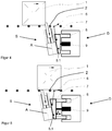
- the stopper S which consists essentially of a cam 3 for stopping the conveyed material 1, a guide 4 and a permanent-electrical Drive 5 consists.
- the cam 3 is guided by its guide 4 in a direction rotated by the angle ß against the perpendicular to the direction of movement of the Fordergutes 1 along an axis A and actuated by the permanent-electric drive 5.
- the drive 5 is designed in the form of a reversible lifting magnet and is connected in particular directly to the cam 3 with the actuating rod of Umlosehubmagneten and closes below the cam 3 is arranged on the linear guide 4, wherein the reversible solenoid (drive 5) the same inclination by the angle ß with respect to the vertical.
- the reversible solenoid (drive 5) the same inclination by the angle ß with respect to the vertical.
- the cam 3 has in the direction of the conveyed material 1 to be stopped a contact surface 3.1, which is oriented substantially vertically.
- Task of the cam 3 is the obstacle of the conveyed 1 with the conveyor 2 running on the further movement.
- the stopper S When striking the conveyed 1 according to FIG. 2 the stopper S must absorb the kinetic energy. After the degradation of the kinetic energy remains a load in the form of a static force by the friction between the conveyor 2 and 1 conveyed on the cam. 3
- the drive 5 has a specific force-displacement curve, which is realized by the combination of a special magnetic drive with a spring combination and therefore has a large holding force in the end position when de-energized. As a result, he is able to absorb significant forces without additional mechanical means for force reversal (for example toggle lever) or detent despite the inclination by the angle ⁇ , without being pushed out of the end position.
- FIG. 3 shows the "opening" of the stopper, with only the frictional force between the cam 3 and conveyed 1 and in the guide 4 of the cam 3 must be overcome. Due to the friction, the conveyed material 1 sets against its mechanical inertia again Move. Due to the inclination of the cam 3 and the high initial acceleration or speed of the cam 3 upon actuation of the drive 5 (Um Spotifyhubmagnet) and in the arrow direction at an angle ⁇ downward movement of the cam 3, immediately creates a gap X between the contact surface 3.1 of Cam 3 and the conveyed 1. This reduces after tearing off the cam 3 from the conveyed material 1, the force required to drive the cam on the self-friction force of the system drive cam guide.
- the damping device D is not integrated into the cam 3.
- the entire stopper S is placed on a separate damping assembly D, which for example comprises a guided carriage 8, which carries the stopper S and a pressure plate 8.1, with which the stopper S is connected.
- This carriage 8 moves parallel to the conveyor 2 and is braked in its movement by a damper 9.
- the damper D is also arranged parallel to the conveyor 2 and attenuates the stop of the conveyed material 1 to the cam third
- a lever 6 is placed in the movement path of the conveyed material 1, which is actuated by the conveyed material 1 and by means of a transferring mechanism 7, the stopper S in the starting position according to FIG. 5 emotional.
- FIG. 4 shows the arrangement of stopper S and damping assembly D after completion of the damping movement.
- FIG. 5 It is shown how the conveyed 1 has moved the damping device D again to the travel a in its initial position during the override, as with the lever 6, the carriage 8 with the pressure plate 8.1 and the stopper S recorded thereon again to the travel S in the in FIG. 5 shown output tray is moved.
- the cam 3 is in a lower position, in which the conveyed 1 can drive over the cam 3.
- the cam 3 is moved with the drive 5 back up to an upper position for stopping the conveyed material 1 ( Fig. 2 and 4 ) and the cycle can start over.
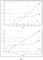
- FIG. 6 is the characteristic K M, the characteristic of the magnet in a force-displacement diagram shown.
- a force of about 400N is realized at the moment of the start of the movement of the cam, which then drops sharply in the course of the first two millimeters of movement and thus after tearing off the cam from the conveyed material and the acceleration phase (curve K M + F ).
- the remaining driving force which moves between about 60 and 150 N, only serves to overcome the inherent friction in the stopper.
- FIG. 7 shows in two diagrams the processes of the horizontal portions of path N s (distance share cam), F s (distance share conveyed) and speed N v (speed share cam), F v (speed share conveyed) of the stop cam and the conveyed material as a function of time and cam lift ,
- the advance of the cam can be seen from the characteristics of the material to be conveyed and cam, since these characteristics do not intersect after the start of the movement.
- Both the horizontal path portion, as well as the speed of the stop cam are considerably higher depending on the time, as well as in dependence of the path compared to the respective characteristics of the conveyed material 1. This effect is achieved by means of the inclination of the stop cam 3 by 12 °.
Abstract
Die Erfindung betrifft eine Vorrichtung zum Stoppen eines Fördergutes auf einem Förderer, aufweisend einen Stopper (S) mit einem Nocken (3) zum Stoppen eines Fördergutes (1), wobei der Nocken (3) im Vergleich zu einer Senkrechten zur Bewegungsrichtung des Fördergutes (1) in einer Winkelstellung um einen Winkel (²) entlang einer Achse (A) verfahrbar und mittels eines Antriebes betätigbar ist.The invention relates to a device for stopping a conveyed material on a conveyor, comprising a stopper (S) with a cam (3) for stopping a conveyed material (1), wherein the cam (3) compared to a perpendicular to the direction of movement of the conveyed material (1 ) in an angular position by an angle (²) along an axis (A) and can be actuated by means of a drive.
Description
Die Erfindung betrifft eine Vorrichtung zu Stoppen eines Fördergutes auf einem Förderer und findet insbesondere für den Transport von Gütern auf Förderstrecken Anwendung.The invention relates to a device for stopping a conveyed material on a conveyor and finds particular application for the transport of goods on conveyor lines.
Für Vereinzelung und Stoppen von Transportgut in kontinuierlich fördernden Transportsystemen der innerbetrieblichen Verkettung werden in großer Zahl mechanische Stopper genutzt. Bei mechanischen Stoppern hält ein Mechanismus das Fördergut auf dem Förderer zurück und gibt dieses bei Bedarf durch Entfernen dieses Elementes zum Weiterfördern frei. Der Befehl zur Betätigung des Stoppers wird in den meisten Anwendungen in Form eines elektrischen Ausgangs-Signals einer SPS-Steuerung bereitgestellt. Für die Betätigung des Mechanismus kommen überwiegend pneumatische Antriebe zum Einsatz. Je nach Masse, Geschwindigkeit und Beschaffenheit des Fördergutes ist eine Dämpfungsfunktion erforderlich, welche üblicherweise in den Mechanismus zum Zurückhalten des Fördergutes integriert ist.
Dieser Mechanismus muss nach Abschluss der dämpfenden Bewegung in seiner Endlage arretiert werden, damit Fördergut, welches im Rahmen der direkt auf dem Fördersystem ausgeführten Fertigungsprozesse nach oben angehoben wurde, beim Absenken nicht auf die inzwischen wieder ausgefahrene Mechanik abgesetzt wird.
Nach der Freigabe des Fördergutes zur weiteren Förderung wird bis zum Schließen des Stoppers die Dämpfungsmechanik wieder ausgefahren, um für den nächsten Dämpfungsvorgang bereit zu sein.
Bei hydraulischen Dämpfungssystemen, die in der Regel mit einer Rückstellfeder versehen sind, wird diese Funktionalität durch eine Rastung, die nach dem Dämpfungsvorgang die Endlage entgegen der Federkraft erhält sowie einer Entriegelung dieser Rastung, welche durch ein zusätzliches Betätigungselement bei der HubBewegung des Stoppers wirksam wird, gewährleistet.
Bei pneumatischen Dämpfern wird von der Druckluft, die zum Schließen des Stoppers verwendet wird ein Teilvolumen abgezweigt und damit der Dämpfungskolben wieder in seine Ausgangsstellung gebracht.For the separation and stopping of transported goods in continuously conveying transport systems of in-plant chaining, mechanical stoppers are used in large numbers. With mechanical stoppers, a mechanism retains the conveyed material on the conveyor and releases it if necessary by removing this element for further conveying. The command to operate the stopper is provided in most applications in the form of an electrical output signal from a PLC controller. For the operation of the mechanism predominantly pneumatic drives are used. Depending on the mass, speed and nature of the material to be conveyed a damping function is required, which is usually integrated into the mechanism for retaining the conveyed material.
This mechanism must be locked in its final position after completion of the damping movement, so that conveyed material, which was lifted upwards within the framework of the production processes carried out directly on the conveyor system, is not deposited on the mechanism that has now been extended when lowered.
After the release of the material to be conveyed further until the closing of the stopper, the damping mechanism is extended again to be ready for the next damping process.
In hydraulic damping systems, which are usually provided with a return spring, this functionality is achieved by a detent, which receives the end position against the spring force after the damping process and an unlocking of this detent, which is effective by an additional actuator in the stroke movement of the stopper, guaranteed.
In the case of pneumatic dampers, a partial volume is branched off from the compressed air used to close the stop, thus bringing the damping piston back into its starting position.
Auf Grund der stark steigenden Energiepreise sowie der Forderungen, die sich aus dem Umweltschutz ergeben, wachsen die Bestrebungen der Industrie, bei den Fertigungsanlagen den Energieverbrauch kontinuierlich zu senken. Ein großes Potential bietet dabei der Verzicht auf die Verwendung von Druckluft als Energieträger für Bewegungen in Industrieanlagen.Due to the sharp increase in energy prices and the demands arising from environmental protection, the industry's efforts to continuously reduce energy consumption in its production facilities are growing. There is a great potential in doing away with the use of compressed air as an energy source for movements in industrial plants.
Daher wurden elektrisch angetriebene Stopper entwickelt, die auf Grund der Verwendung komplizierter Mechanismen gegenüber den pneumatischen Lösungen jedoch einen wesentlich höheren Preis besitzen, wesentlich mehr Bauraum benötigen und einen hohen Stromverbrauch aufweisen.Therefore, electrically driven stoppers have been developed which, however, have a much higher price due to the use of complicated mechanisms compared to the pneumatic solutions, require much more space and have a high power consumption.
In der Druckschrift
Des Weiteren bedeutet diese Kinematik ein hohes Eigengewicht der beweglichen Teile, wodurch eine hohe Geschwindigkeit zum Lösen des Stoppers von dem Transportgut nicht erreicht wird. Daraus resultiert ein hoher Kraftaufwand und Energieaufwand zum Lösen der Verbindung zwischen Transportgut und Stopper.In the publication
Furthermore, this kinematics means a high weight of the moving parts, whereby a high speed for releasing the stopper is not achieved by the transported goods. This results in a high expenditure of energy and energy to release the connection between cargo and stopper.
Die Druckschrift
Aus der Druckschrift
In der Druckschrift
Aufgabe der Erfindung ist es, eine Vorrichtung zum Stoppen eines Fördergutes auf einem Förderer zu entwickeln, welche einen einfachen konstruktiven Aufbau aufweist, hohe Haltekräfte umsetzt und dabei energiesparend arbeitet.The object of the invention is to develop a device for stopping a conveyed on a conveyor, which has a simple structural design, high holding forces and thereby works to save energy.
Diese Aufgabe wird mit den kennzeichnenden Merkmalen des ersten Patentanspruchs gelöst.
Vorteilhafte Ausgestaltungen ergeben sich aus den Unteransprüchen.This object is achieved with the characterizing features of the first claim.
Advantageous embodiments emerge from the subclaims.
Die Erfindung betrifft eine Vorrichtung zum Stoppen eines Fördergutes auf einem Förderer, aufweisend einen Stopper mit einem Nocken zum Stoppen eines Fördergutes, wobei der Nocken im Vergleich zu einer Senkrechten zur Bewegungsrichtung des Fördergutes in einer Winkelstellung um einen Winkel entlang einer Achse verfahrbar und mittels eines Antriebes betätigbar ist.
Der gesamte Stopper einschließlich seines Antriebs kann dazu eine Schrägstellung entlang einer Achse A um den Winkel β gegen die Senkrechte zur Bewegungsrichtung des Fördergutes aufweisen.
Bevorzugt ist der Nocken in einer Linearführung des Stoppers mit einer hohen Geschwindigkeit verstellbar, wobei der Nocken auf Grund der Schrägstellung im Winkel und der hohen Geschwindigkeit beim Verstellen zur Freigabe des Fördergutes vom wieder anlaufenden Fördergut nicht einholbar ist, sodass nach dem Abreißen des Nockens vom Fördergut die erforderliche Kraft für den Antrieb des Nockens auf die Eigenreibungskraft des Systems Antrieb-Nocken-Führung reduzierbar ist.The invention relates to a device for stopping a material to be conveyed on a conveyor, comprising a stopper with a cam for stopping a conveyed material, wherein the cam compared to a perpendicular to the direction of movement of the conveyed in an angular position by an angle along an axis movable and by means of a drive is operable.
The entire stopper including its drive can for this purpose have an inclination along an axis A by the angle β against the perpendicular to the direction of movement of the conveyed material.
Preferably, the cam is adjustable in a linear guide of the stopper at a high speed, the cam due to the skew at an angle and the high speed when adjusting the release of the conveyed from restarting conveyed is not recoverable, so after tearing off the cam from the conveyed the required force for driving the cam on the self-friction force of the system drive cam guide is reduced.
Für die Verstellung weist der Stopper eine anwendungsabhängige Kraft-Weg-Kennlinie und Weg-Zeit-Kennlinie auf. Im Moment des Starts der Bewegung des Nockens wird durch den Antrieb eine Kraft von mindestens 300 N, bevorzugt von ca. 400N oder darüber realisiert, die dann im Verlauf der ersten zwei Millimeter der Bewegung und damit nach Abreißen des Nocken vom Fördergut und der Beschleunigungsphase stark abfällt. Die verbleibende Antriebskraft, die sich zwischen ca. 60 und 150 N bewegt, dient lediglich noch zur Überwindung der Eigenreibung im Stopper.For the adjustment, the stopper on an application-dependent force-displacement curve and path-time characteristic. At the moment of the start of the movement of the cam by the drive, a force of at least 300 N, preferably of about 400N or above realized, then strong in the course of the first two millimeters of movement and thus after tearing the cam from the conveyed and the acceleration phase drops. The remaining driving force, which moves between about 60 and 150 N, only serves to overcome the inherent friction in the stopper.
An die die Linearführung unterhalb des Nockens schließt sich der Antrieb an, der direkt mit dem Nocken verbunden ist und in dem gleichen Winkel wie der Nocken geneigt ist. Dadurch reduziert sich die Reibung des Systems Stopper auf den Nocken, die Führung und den insbesondere elektrische betätigbaren Antrieb.To the the linear guide below the cam, the drive connects, which is directly connected to the cam and is inclined at the same angle as the cam. This reduces the friction of the system stopper on the cam, the guide and the particular electric actuated drive.
Der Stopper bzw. der Nocken des Stoppers weist eine anwendungsabhängige Kraft-Weg-Kennlinie und Weg-Zeit-Kennlinie aufweist, wobei die Geschwindigkeit und der daraus resultierend auch der Weganteil des Stoppers bzw. Nockens dabei erheblich höher in Abhängigkeit der Zeit, als auch in Abhängigkeit des Weges im Vergleich zu den jeweiligen Kennlinien des Fördergutes liegen.The stopper or the cam of the stopper has an application-dependent force-displacement curve and path-time characteristic, wherein the speed and the resulting also the path portion of the stopper or cam thereby considerably higher Dependence of the time, as well as depending on the way in comparison to the respective characteristics of the conveyed are.
Zum Erreichen der hohen Beschleunigungswerte und Geschwindigkeiten ist der Antrieb in Form eines elektrischen Antriebs, vorzugsweise in Form eines Umkehr-Hubmagnets ausgebildet, wobei eine Betätigungsstange des Umkehrhubmagneten direkt mit dem Nocken verbunden ist und dadurch die Stellbewegung des Umkehrhubmagneten direkt auf den Nocken übertragen wird. Alternativ ist der Nocken direkt an dem UmkehrHubmagnet ausgebildet, z.B. direkt an der Betätigungsstange des Umkehrhubmagneten so dass keine weiteren Verbindungselemente zwischen dem Nicken und der Betätigungsstange des Umkehrhubmagneten erforderlich sind. Ist der Nocken separat ausgebildet und an der Betätigungsstange des Umkehrhubmagneten befestigt kann der Nocken auch höhenverstellbar an der Betätigungsstange angebracht sein.
Vorteilhafter Weise wird dabei immer die in einem Winkel zur Senkrechten vollführte lineare Hubbewegung des Umkehr-Hubmagnets direkt an den Nocken übertragen, der in dem gleichen Winkel in der Linearführung angeordnet ist.To achieve the high acceleration values and speeds, the drive is in the form of an electric drive, preferably in the form of a reversible solenoid, wherein an actuating rod of Umkehrhubmagneten is directly connected to the cam and thereby the actuating movement of the Umkehrhubmagneten is transmitted directly to the cam. Alternatively, the cam is formed directly on the reversing lifting magnet, eg directly on the operating rod of the reversing lifting magnet, so that no further connecting elements between the pitch and the operating rod of the reversing lifting magnet are required. If the cam is formed separately and attached to the actuating rod of Umkehrhubmagneten the cam can also be mounted vertically adjustable on the actuating rod.
Advantageously, always the executed at an angle to the vertical linear stroke of the reverse solenoid is transmitted directly to the cam, which is arranged at the same angle in the linear guide.
Die Anordnung des Nockens mit direkter Verbindung an den Umkehr-Hubmagnet ermöglicht eine Beschleunigung des Nockens von über 300m/s2 vorzugsweise von 400m/s2 oder mehr und eine Geschwindigkeit des Nockens (3) von über 1m/s, vorzugsweise in der Größenordnung von 1,5 bis 2 m/s oder mehr.The arrangement of the cam with direct connection to the reverse solenoid allows an acceleration of the cam of over 300m / s 2, preferably 400m / s 2 or more and a speed of the cam (3) of about 1m / s, preferably of the order of 1.5 to 2 m / s or more.
Der Antrieb des Stopper ist vorzugsweise in Form eines permanentmagnetischen Umkehr-Hubmagneten ausgebildet. Diese generieren schnelle Bewegungen und hohe Halte- und Abreißkräfte in der oberen Endlage und beim Anlaufen.The drive of the stopper is preferably designed in the form of a permanent magnet reversible lifting magnet. These generate fast movements and high holding and tear-off forces in the upper end position and during start-up.
Des Weiteren weist der Antrieb bei Ausführung als permanentmagnetischer Umkehrhubmagnet im stromlosen Zustand hohe Haltekräfte in seiner Endlage auf.Furthermore, the drive in execution as a permanent magnetic Umkehrhubmagnet in the de-energized state high holding forces in its final position.
Der Nocken des Stoppers ist in einer Führung geführt, womit sich die Reibung des Systems Stopper auf den Nocken, die Führung und den elektrischen Antrieb begrenzt.The cam of the stopper is guided in a guide, which limits the friction of the system stopper on the cam, the guide and the electric drive.
Die Vorrichtung besteht aus dem elektrischen bzw. elektromagnetisch betätigbaren Stopper sowie der zugehörigen Dämpfungseinrichtung wobei diese nicht in den Stopper integriert sondern als separates Bauteil ausgebildet ist. Dies ermöglicht durch die geringe bewegte Masse beim Öffnen des Stoppers eine sehr schnelle Bewegung unter geringem Energieeinsatz.The device consists of the electric or electromagnetically operable stopper and the associated damping device which is not integrated in the stopper but is designed as a separate component. This is made possible by the low moving mass when opening the stopper a very fast movement with low energy input.
Der Stopper steht mit der Dämpfungseinrichtung in Wirkverbindung, wobei der Stopper beim Anschlagen eines Fördergutes parallel zum Förderer in Richtung der Dämpfungseinrichtung bewegbar ist. Während dieser Bewegung wird er durch einen in der Dämpfungseinrichtung befindlichen Dämpfer abgebremst, wobei der Dämpfer ebenfalls parallel zum Förderer montiert ist und beim Anschlagen des Fördergutes an den Stopper komprimiert wird.The stopper is in operative connection with the damping device, wherein the stopper is movable parallel to the conveyor in the direction of the damping device when striking a conveyed material. During this movement, it is braked by a damper located in the damping device, wherein the damper is also mounted parallel to the conveyor and is compressed when striking the material to be conveyed to the stopper.
Der Stopper ist dafür auf einem Schlitten parallel zum Förderer verschiebbar gelagert, woraus sich die Komprimierung des fest stehenden Dämpfers ergibt.The stopper is slidably mounted on a carriage parallel to the conveyor, resulting in the compression of the fixed damper.
Die Dämpfungseinrichtung weist einen Hebel auf, wobei der Hebel mittels des diesen überfahrenden Fördergutes betätigbar ist derart, dass die Dämpfungseinrichtung mittels des Hebels in ihre Ausgangslage bringbar ist. Nach dem Passieren des Stoppers wird der Nocken wieder nach oben bewegt und der Zyklus kann von vorn beginnen. Die Rückstellung des Dämpfers erfolgt somit ohne zusätzliche Energie, es wird keine Druckluft benötigt.The damping device has a lever, wherein the lever can be actuated by means of the conveyed material passing over it such that the damping device can be brought into its starting position by means of the lever. After passing the stopper, the cam is moved up again and the cycle can start again. The provision of the damper thus takes place without additional energy, it is not required compressed air.
Die Erfindung wird nachfolgend an einem Ausführungsbeispiel und zugehörigen Zeichnungen näher erläutert.The invention will be explained in more detail below using an exemplary embodiment and associated drawings.
Es zeigen:
Figur 1- den Stopper der erfindungsgemäßen Vorrichtung,
Figur 2- das an dem Stopper anschlagende Fördergut,
Figur 3- das Lösen des Stoppers und das Anfahren des Fördergutes,
Figur 4- die erfindungsgemäße Vorrichtung bestehend aus Stopper und Dämpfungseinrichtung,
Figur 5- die Rückstellung der Dämpfungseinrichtung,
Figur 6- Diagramm Kraft-Weg des elektrischen Antriebs,
Figur 7- zwei Diagramme zu Fördergut und Stopper bezüglich des Geschwindigkeits- und Weganteils in Abhängigkeit der Zeit und des Weges.
- FIG. 1
- the stopper of the device according to the invention,
- FIG. 2
- the conveyed goods striking the stopper,
- FIG. 3
- the release of the stopper and the start of the conveyed material,
- FIG. 4
- the device according to the invention consisting of stopper and damping device,
- FIG. 5
- the return of the damping device,
- FIG. 6
- Diagram force-path of the electric drive,
- FIG. 7
- Two diagrams of material to be conveyed and stopper with regard to the speed and distance component as a function of time and distance.
Gemäß
Der Antrieb 5 ist in Form eines Umkehr-Hubmagneten ausgebildet und ist mit der Betätigungsstange des Umkehrhubmagneten insbesondere direkt mit dem Nocken 3 verbunden und schließt unterhalb des des Nockens 3 sich an die Linearführung 4 anschließend angeordnet, wobei der Umkehr-Hubmagnet (Antrieb 5) die selbe Schrägstellung um den Winkel ß in Bezug auf die Senkrechte aufweist. Es erfolgt eine direkte Übertragung der Hub-Bewegung der Betätigungsstange 5.1 des UmkehrHubmagneten (Antrieb 5) auf den Nocken 3.
Der Nocken 3 weist in Richtung zu dem zu stoppenden Fördergut 1 eine Anlagefläche 3.1 auf, die im Wesentlichen senkrecht ausgerichtet ist.According to
The
The
Aufgabe des Nockens 3 ist das Hindern des Förderguts 1 bei laufendem Förderer 2 an der weiteren Bewegung.Task of the
Beim Anschlagen des Fördergutes 1 gemäß
Der Antrieb 5 hat eine spezifische Kraft-Weg-Kennlinie, die durch die Kombination eines speziellen Magnetantriebes mit einer Federkombination realisiert wird und besitzt daher im stromlosen Zustand eine große Haltekraft in der Endlage. Dadurch ist er in der Lage, ohne zusätzliche mechanische Einrichtungen zur Kraftumkehr (z.B. Kniehebel) oder Rastung trotz der Schrägstellung um den Winkel β erhebliche Kräfte aufzunehmen, ohne aus der Endlage gedrückt zu werden.The
Dieser Mechanismus des Stoppers S beim Öffnen ist nur wirksam, so lange sich der Nocken 3 des Stoppers S so schnell bewegt, dass er vom wieder anlaufenden Fördergut 1 nicht eingeholt wird. (siehe
Der gesamte Stopper S wird an einer separaten Dämpfungsbaugruppe D platziert, die beispielsweise aus einen geführten Schlitten 8 aufweist, der den Stopper S trägt und eine Druckplatte 8.1 aufweist, mit welcher der Stopper S verbunden ist. Dieser Schlitten 8 bewegt sich parallel zum Förderer 2 und wird in seiner Bewegung durch einen Dämpfer 9 gebremst. Der Dämpfer D ist ebenfalls parallel zum Förderer 2 angeordnet und dämpft den Anschlag des Fördergutes 1 an den Nocken 3.This mechanism of the stopper S when opening is only effective, as long as the
The entire stopper S is placed on a separate damping assembly D, which for example comprises a guided
Um die Dämpfungbaugruppe D nach dem Passieren des Stoppers 1 ohne zusätzlichen Antrieb wieder um einen Stellweg a (siehe
In
In
- 11
- Fördergutconveyed
- 22
- Fördererpromoter
- 33
- Nockencam
- 3.13.1
- Anlageflächecontact surface
- 44
- Führungguide
- 55
- Elektrischer AntriebElectric drive
- 66
- Hebellever
- 77
- Übertragender MechanismusTransferring mechanism
- 88th
- Schlittencarriage
- 8.18.1
- Druckplatteprinting plate
- 99
- Dämpferdamper
- aa
- StellwegTravel Range
- AA
- Achseaxis
- DD
- Dämpfungsbaugruppedamping assembly
- KM+F K M + F
- Magnetkraft Magnet+FederMagnetic force magnet + spring
- KM K M
- Magnetkraft MagnetMagnetic force magnet
- Ns N s
- horizontaler Weganteil Nockenhorizontal path portion cams
- Nv N v
- horizontaler Geschwindigkeitsanteil Nockenhorizontal speed component cam
- Fs F s
- horizontaler Weganteil Förderguthorizontal path portion of conveyed material
- Fv F v
- horizontaler Geschwindkeitsanteil Förderguthorizontal speed proportion of transported goods
- SS
- Stopperstopper
Claims (13)
Applications Claiming Priority (2)
| Application Number | Priority Date | Filing Date | Title |
|---|---|---|---|
| DE102016110400.0A DE102016110400A1 (en) | 2016-06-06 | 2016-06-06 | Device for stopping a conveyed material on a conveyor |
| DE202017103367.8U DE202017103367U1 (en) | 2017-06-02 | 2017-06-02 | Device for stopping a conveyed material on a conveyor |
Publications (2)
| Publication Number | Publication Date |
|---|---|
| EP3254997A1 true EP3254997A1 (en) | 2017-12-13 |
| EP3254997B1 EP3254997B1 (en) | 2019-03-06 |
Family
ID=59053931
Family Applications (1)
| Application Number | Title | Priority Date | Filing Date |
|---|---|---|---|
| EP17174516.9A Active EP3254997B1 (en) | 2016-06-06 | 2017-06-06 | Device for stopping a converted item on a conveyor |
Country Status (1)
| Country | Link |
|---|---|
| EP (1) | EP3254997B1 (en) |
Cited By (1)
| Publication number | Priority date | Publication date | Assignee | Title |
|---|---|---|---|---|
| CN108974908A (en) * | 2018-07-27 | 2018-12-11 | 东莞市联洲知识产权运营管理有限公司 | A kind of protective cover structure for conveying on relay packing device |
Citations (10)
| Publication number | Priority date | Publication date | Assignee | Title |
|---|---|---|---|---|
| US3532201A (en) * | 1968-09-23 | 1970-10-06 | Interlake Steel Corp | Conveyor load spacer |
| EP0193740A2 (en) * | 1985-03-05 | 1986-09-10 | SKF Nova AB | A blocking device for objects conveyed upon a conveyor track |
| DE8906202U1 (en) * | 1989-05-19 | 1989-09-07 | Heinrich Niederberger Kg, 8172 Lenggries, De | |
| JPH0261825U (en) * | 1988-10-25 | 1990-05-09 | ||
| JPH07112822A (en) * | 1993-10-18 | 1995-05-02 | Murata Mach Ltd | Stopper of goods to be carried on roller conveyer |
| JPH07267359A (en) * | 1994-03-25 | 1995-10-17 | Nippon Steel Corp | Overload canceling mechanism in steel plate stopping device |
| JPH08108931A (en) * | 1994-10-12 | 1996-04-30 | Murata Mach Ltd | Stopper device |
| FR2729936A1 (en) * | 1995-01-30 | 1996-08-02 | Sipa Roller | SECURITY SYSTEM FOR LOAD SEPARATION DEVICE IN A DYNAMIC STORAGE CORRIDOR |
| DE102006028493A1 (en) * | 2006-06-21 | 2007-12-27 | KRUPS Fördersysteme GmbH | stopping device |
| WO2009063562A1 (en) * | 2007-11-15 | 2009-05-22 | Hirata Corporation | Substrate transport device |
-
2017
- 2017-06-06 EP EP17174516.9A patent/EP3254997B1/en active Active
Patent Citations (10)
| Publication number | Priority date | Publication date | Assignee | Title |
|---|---|---|---|---|
| US3532201A (en) * | 1968-09-23 | 1970-10-06 | Interlake Steel Corp | Conveyor load spacer |
| EP0193740A2 (en) * | 1985-03-05 | 1986-09-10 | SKF Nova AB | A blocking device for objects conveyed upon a conveyor track |
| JPH0261825U (en) * | 1988-10-25 | 1990-05-09 | ||
| DE8906202U1 (en) * | 1989-05-19 | 1989-09-07 | Heinrich Niederberger Kg, 8172 Lenggries, De | |
| JPH07112822A (en) * | 1993-10-18 | 1995-05-02 | Murata Mach Ltd | Stopper of goods to be carried on roller conveyer |
| JPH07267359A (en) * | 1994-03-25 | 1995-10-17 | Nippon Steel Corp | Overload canceling mechanism in steel plate stopping device |
| JPH08108931A (en) * | 1994-10-12 | 1996-04-30 | Murata Mach Ltd | Stopper device |
| FR2729936A1 (en) * | 1995-01-30 | 1996-08-02 | Sipa Roller | SECURITY SYSTEM FOR LOAD SEPARATION DEVICE IN A DYNAMIC STORAGE CORRIDOR |
| DE102006028493A1 (en) * | 2006-06-21 | 2007-12-27 | KRUPS Fördersysteme GmbH | stopping device |
| WO2009063562A1 (en) * | 2007-11-15 | 2009-05-22 | Hirata Corporation | Substrate transport device |
Cited By (1)
| Publication number | Priority date | Publication date | Assignee | Title |
|---|---|---|---|---|
| CN108974908A (en) * | 2018-07-27 | 2018-12-11 | 东莞市联洲知识产权运营管理有限公司 | A kind of protective cover structure for conveying on relay packing device |
Also Published As
| Publication number | Publication date |
|---|---|
| EP3254997B1 (en) | 2019-03-06 |
Similar Documents
| Publication | Publication Date | Title |
|---|---|---|
| EP1902981A1 (en) | Stop module | |
| EP1902982A1 (en) | Stop module | |
| DE102017212660A1 (en) | suction device | |
| EP1554109B1 (en) | Device for punching, stamping and/or shaping flat elements | |
| EP3096899B1 (en) | Joining device, preferably for applying rivets, for clinching or for punching | |
| DE102013202674A1 (en) | Transport apparatus for promoting e.g. shock-sensitive chocolate bars, has conveying element comprising permanent magnets, and power generation and storage units actuated by movement of conveying elements | |
| EP3254997B1 (en) | Device for stopping a converted item on a conveyor | |
| DE102014110822A1 (en) | Stop module for positionally accurate stopping of an object | |
| DE202017103367U1 (en) | Device for stopping a conveyed material on a conveyor | |
| DE102009029664A1 (en) | Transmission module for transferring parts between stations | |
| DE2456381B2 (en) | DEVICE FOR CONTROLLING THE FLOW RATE OF ADJUSTABLE AXIAL PISTON PUMPS | |
| DE102016110400A1 (en) | Device for stopping a conveyed material on a conveyor | |
| DE2251536B2 (en) | CONTROL AND REGULATING DEVICE FOR A CONTINUOUSLY ADJUSTABLE HYDROSTATIC TRANSMISSION FOR VEHICLES, IN PARTICULAR FOR LIFT TRUCKS, SHOVEL LOADERS OR THE DIGITAL. | |
| EP3524488A1 (en) | Outlet device for controlling the gap of an outlet opening of a transport silo set up to discharge bulk goods by means of gravity through this outlet device | |
| EP2455208B1 (en) | Apparatus and process for base mould lift damping | |
| EP1900669A2 (en) | Device for positioning the trailing edge of sheets | |
| DE102006003851A1 (en) | Apparatus for molding, stamping and stacking deep-drawn components, includes independently regulated drive for tilting linear guide for lower mold and drive for displacing lower mold | |
| DE10304021B4 (en) | Device for aligning sheets in the boom of a sheet-processing machine | |
| DE102011122492A1 (en) | Press unit e.g. hydraulic press unit, for transfer press for e.g. embossing of thin metal sheet in industrial production application, has drive mechanism formed such that pressing force is enlarged by current feed of plate and solenoids | |
| DE2812973C2 (en) | Device for damping the cutting impact on a hydraulic press | |
| EP2483065A1 (en) | Method for moving a machining unit of a machine | |
| EP1354835B1 (en) | Driving device for a folding blade | |
| DE2047669C3 (en) | Control device for selecting one of two transport speeds for card or strip punches | |
| DE1927559B2 (en) | Plunger limit switch with limited swivel angle | |
| DE2348114C3 (en) | Safety flap for room ventilation |
Legal Events
| Date | Code | Title | Description |
|---|---|---|---|
| PUAI | Public reference made under article 153(3) epc to a published international application that has entered the european phase |
Free format text: ORIGINAL CODE: 0009012 |
|
| STAA | Information on the status of an ep patent application or granted ep patent |
Free format text: STATUS: THE APPLICATION HAS BEEN PUBLISHED |
|
| AK | Designated contracting states |
Kind code of ref document: A1 Designated state(s): AL AT BE BG CH CY CZ DE DK EE ES FI FR GB GR HR HU IE IS IT LI LT LU LV MC MK MT NL NO PL PT RO RS SE SI SK SM TR |
|
| AX | Request for extension of the european patent |
Extension state: BA ME |
|
| STAA | Information on the status of an ep patent application or granted ep patent |
Free format text: STATUS: REQUEST FOR EXAMINATION WAS MADE |
|
| 17P | Request for examination filed |
Effective date: 20180129 |
|
| RBV | Designated contracting states (corrected) |
Designated state(s): AL AT BE BG CH CY CZ DE DK EE ES FI FR GB GR HR HU IE IS IT LI LT LU LV MC MK MT NL NO PL PT RO RS SE SI SK SM TR |
|
| GRAP | Despatch of communication of intention to grant a patent |
Free format text: ORIGINAL CODE: EPIDOSNIGR1 |
|
| STAA | Information on the status of an ep patent application or granted ep patent |
Free format text: STATUS: GRANT OF PATENT IS INTENDED |
|
| INTG | Intention to grant announced |
Effective date: 20180920 |
|
| GRAS | Grant fee paid |
Free format text: ORIGINAL CODE: EPIDOSNIGR3 |
|
| GRAA | (expected) grant |
Free format text: ORIGINAL CODE: 0009210 |
|
| STAA | Information on the status of an ep patent application or granted ep patent |
Free format text: STATUS: THE PATENT HAS BEEN GRANTED |
|
| AK | Designated contracting states |
Kind code of ref document: B1 Designated state(s): AL AT BE BG CH CY CZ DE DK EE ES FI FR GB GR HR HU IE IS IT LI LT LU LV MC MK MT NL NO PL PT RO RS SE SI SK SM TR |
|
| REG | Reference to a national code |
Ref country code: GB Ref legal event code: FG4D Free format text: NOT ENGLISH |
|
| REG | Reference to a national code |
Ref country code: CH Ref legal event code: EP Ref country code: AT Ref legal event code: REF Ref document number: 1104247 Country of ref document: AT Kind code of ref document: T Effective date: 20190315 |
|
| REG | Reference to a national code |
Ref country code: DE Ref legal event code: R096 Ref document number: 502017000871 Country of ref document: DE |
|
| REG | Reference to a national code |
Ref country code: IE Ref legal event code: FG4D Free format text: LANGUAGE OF EP DOCUMENT: GERMAN |
|
| REG | Reference to a national code |
Ref country code: NL Ref legal event code: MP Effective date: 20190306 |
|
| REG | Reference to a national code |
Ref country code: LT Ref legal event code: MG4D |
|
| PG25 | Lapsed in a contracting state [announced via postgrant information from national office to epo] |
Ref country code: FI Free format text: LAPSE BECAUSE OF FAILURE TO SUBMIT A TRANSLATION OF THE DESCRIPTION OR TO PAY THE FEE WITHIN THE PRESCRIBED TIME-LIMIT Effective date: 20190306 Ref country code: NO Free format text: LAPSE BECAUSE OF FAILURE TO SUBMIT A TRANSLATION OF THE DESCRIPTION OR TO PAY THE FEE WITHIN THE PRESCRIBED TIME-LIMIT Effective date: 20190606 Ref country code: LT Free format text: LAPSE BECAUSE OF FAILURE TO SUBMIT A TRANSLATION OF THE DESCRIPTION OR TO PAY THE FEE WITHIN THE PRESCRIBED TIME-LIMIT Effective date: 20190306 Ref country code: SE Free format text: LAPSE BECAUSE OF FAILURE TO SUBMIT A TRANSLATION OF THE DESCRIPTION OR TO PAY THE FEE WITHIN THE PRESCRIBED TIME-LIMIT Effective date: 20190306 |
|
| PG25 | Lapsed in a contracting state [announced via postgrant information from national office to epo] |
Ref country code: LV Free format text: LAPSE BECAUSE OF FAILURE TO SUBMIT A TRANSLATION OF THE DESCRIPTION OR TO PAY THE FEE WITHIN THE PRESCRIBED TIME-LIMIT Effective date: 20190306 Ref country code: NL Free format text: LAPSE BECAUSE OF FAILURE TO SUBMIT A TRANSLATION OF THE DESCRIPTION OR TO PAY THE FEE WITHIN THE PRESCRIBED TIME-LIMIT Effective date: 20190306 Ref country code: RS Free format text: LAPSE BECAUSE OF FAILURE TO SUBMIT A TRANSLATION OF THE DESCRIPTION OR TO PAY THE FEE WITHIN THE PRESCRIBED TIME-LIMIT Effective date: 20190306 Ref country code: BG Free format text: LAPSE BECAUSE OF FAILURE TO SUBMIT A TRANSLATION OF THE DESCRIPTION OR TO PAY THE FEE WITHIN THE PRESCRIBED TIME-LIMIT Effective date: 20190606 Ref country code: GR Free format text: LAPSE BECAUSE OF FAILURE TO SUBMIT A TRANSLATION OF THE DESCRIPTION OR TO PAY THE FEE WITHIN THE PRESCRIBED TIME-LIMIT Effective date: 20190607 Ref country code: HR Free format text: LAPSE BECAUSE OF FAILURE TO SUBMIT A TRANSLATION OF THE DESCRIPTION OR TO PAY THE FEE WITHIN THE PRESCRIBED TIME-LIMIT Effective date: 20190306 |
|
| PG25 | Lapsed in a contracting state [announced via postgrant information from national office to epo] |
Ref country code: EE Free format text: LAPSE BECAUSE OF FAILURE TO SUBMIT A TRANSLATION OF THE DESCRIPTION OR TO PAY THE FEE WITHIN THE PRESCRIBED TIME-LIMIT Effective date: 20190306 Ref country code: AL Free format text: LAPSE BECAUSE OF FAILURE TO SUBMIT A TRANSLATION OF THE DESCRIPTION OR TO PAY THE FEE WITHIN THE PRESCRIBED TIME-LIMIT Effective date: 20190306 Ref country code: SK Free format text: LAPSE BECAUSE OF FAILURE TO SUBMIT A TRANSLATION OF THE DESCRIPTION OR TO PAY THE FEE WITHIN THE PRESCRIBED TIME-LIMIT Effective date: 20190306 Ref country code: PT Free format text: LAPSE BECAUSE OF FAILURE TO SUBMIT A TRANSLATION OF THE DESCRIPTION OR TO PAY THE FEE WITHIN THE PRESCRIBED TIME-LIMIT Effective date: 20190706 Ref country code: CZ Free format text: LAPSE BECAUSE OF FAILURE TO SUBMIT A TRANSLATION OF THE DESCRIPTION OR TO PAY THE FEE WITHIN THE PRESCRIBED TIME-LIMIT Effective date: 20190306 Ref country code: IT Free format text: LAPSE BECAUSE OF FAILURE TO SUBMIT A TRANSLATION OF THE DESCRIPTION OR TO PAY THE FEE WITHIN THE PRESCRIBED TIME-LIMIT Effective date: 20190306 Ref country code: ES Free format text: LAPSE BECAUSE OF FAILURE TO SUBMIT A TRANSLATION OF THE DESCRIPTION OR TO PAY THE FEE WITHIN THE PRESCRIBED TIME-LIMIT Effective date: 20190306 Ref country code: RO Free format text: LAPSE BECAUSE OF FAILURE TO SUBMIT A TRANSLATION OF THE DESCRIPTION OR TO PAY THE FEE WITHIN THE PRESCRIBED TIME-LIMIT Effective date: 20190306 |
|
| PG25 | Lapsed in a contracting state [announced via postgrant information from national office to epo] |
Ref country code: SM Free format text: LAPSE BECAUSE OF FAILURE TO SUBMIT A TRANSLATION OF THE DESCRIPTION OR TO PAY THE FEE WITHIN THE PRESCRIBED TIME-LIMIT Effective date: 20190306 Ref country code: PL Free format text: LAPSE BECAUSE OF FAILURE TO SUBMIT A TRANSLATION OF THE DESCRIPTION OR TO PAY THE FEE WITHIN THE PRESCRIBED TIME-LIMIT Effective date: 20190306 |
|
| REG | Reference to a national code |
Ref country code: DE Ref legal event code: R097 Ref document number: 502017000871 Country of ref document: DE |
|
| PG25 | Lapsed in a contracting state [announced via postgrant information from national office to epo] |
Ref country code: IS Free format text: LAPSE BECAUSE OF FAILURE TO SUBMIT A TRANSLATION OF THE DESCRIPTION OR TO PAY THE FEE WITHIN THE PRESCRIBED TIME-LIMIT Effective date: 20190706 |
|
| PLBE | No opposition filed within time limit |
Free format text: ORIGINAL CODE: 0009261 |
|
| STAA | Information on the status of an ep patent application or granted ep patent |
Free format text: STATUS: NO OPPOSITION FILED WITHIN TIME LIMIT |
|
| PG25 | Lapsed in a contracting state [announced via postgrant information from national office to epo] |
Ref country code: DK Free format text: LAPSE BECAUSE OF FAILURE TO SUBMIT A TRANSLATION OF THE DESCRIPTION OR TO PAY THE FEE WITHIN THE PRESCRIBED TIME-LIMIT Effective date: 20190306 Ref country code: MC Free format text: LAPSE BECAUSE OF FAILURE TO SUBMIT A TRANSLATION OF THE DESCRIPTION OR TO PAY THE FEE WITHIN THE PRESCRIBED TIME-LIMIT Effective date: 20190306 |
|
| 26N | No opposition filed |
Effective date: 20191209 |
|
| PG25 | Lapsed in a contracting state [announced via postgrant information from national office to epo] |
Ref country code: SI Free format text: LAPSE BECAUSE OF FAILURE TO SUBMIT A TRANSLATION OF THE DESCRIPTION OR TO PAY THE FEE WITHIN THE PRESCRIBED TIME-LIMIT Effective date: 20190306 |
|
| REG | Reference to a national code |
Ref country code: BE Ref legal event code: MM Effective date: 20190630 |
|
| PG25 | Lapsed in a contracting state [announced via postgrant information from national office to epo] |
Ref country code: TR Free format text: LAPSE BECAUSE OF FAILURE TO SUBMIT A TRANSLATION OF THE DESCRIPTION OR TO PAY THE FEE WITHIN THE PRESCRIBED TIME-LIMIT Effective date: 20190306 |
|
| PG25 | Lapsed in a contracting state [announced via postgrant information from national office to epo] |
Ref country code: IE Free format text: LAPSE BECAUSE OF NON-PAYMENT OF DUE FEES Effective date: 20190606 |
|
| PG25 | Lapsed in a contracting state [announced via postgrant information from national office to epo] |
Ref country code: BE Free format text: LAPSE BECAUSE OF NON-PAYMENT OF DUE FEES Effective date: 20190630 Ref country code: LU Free format text: LAPSE BECAUSE OF NON-PAYMENT OF DUE FEES Effective date: 20190606 |
|
| PG25 | Lapsed in a contracting state [announced via postgrant information from national office to epo] |
Ref country code: FR Free format text: LAPSE BECAUSE OF NON-PAYMENT OF DUE FEES Effective date: 20190630 |
|
| PG25 | Lapsed in a contracting state [announced via postgrant information from national office to epo] |
Ref country code: CY Free format text: LAPSE BECAUSE OF FAILURE TO SUBMIT A TRANSLATION OF THE DESCRIPTION OR TO PAY THE FEE WITHIN THE PRESCRIBED TIME-LIMIT Effective date: 20190306 |
|
| PG25 | Lapsed in a contracting state [announced via postgrant information from national office to epo] |
Ref country code: MT Free format text: LAPSE BECAUSE OF FAILURE TO SUBMIT A TRANSLATION OF THE DESCRIPTION OR TO PAY THE FEE WITHIN THE PRESCRIBED TIME-LIMIT Effective date: 20190306 Ref country code: HU Free format text: LAPSE BECAUSE OF FAILURE TO SUBMIT A TRANSLATION OF THE DESCRIPTION OR TO PAY THE FEE WITHIN THE PRESCRIBED TIME-LIMIT; INVALID AB INITIO Effective date: 20170606 |
|
| GBPC | Gb: european patent ceased through non-payment of renewal fee |
Effective date: 20210606 |
|
| PG25 | Lapsed in a contracting state [announced via postgrant information from national office to epo] |
Ref country code: GB Free format text: LAPSE BECAUSE OF NON-PAYMENT OF DUE FEES Effective date: 20210606 |
|
| PG25 | Lapsed in a contracting state [announced via postgrant information from national office to epo] |
Ref country code: MK Free format text: LAPSE BECAUSE OF FAILURE TO SUBMIT A TRANSLATION OF THE DESCRIPTION OR TO PAY THE FEE WITHIN THE PRESCRIBED TIME-LIMIT Effective date: 20190306 |
|
| PGFP | Annual fee paid to national office [announced via postgrant information from national office to epo] |
Ref country code: CH Payment date: 20220629 Year of fee payment: 6 |
|
| PGFP | Annual fee paid to national office [announced via postgrant information from national office to epo] |
Ref country code: DE Payment date: 20230314 Year of fee payment: 7 |
|
| REG | Reference to a national code |
Ref country code: AT Ref legal event code: MM01 Ref document number: 1104247 Country of ref document: AT Kind code of ref document: T Effective date: 20220606 |
|
| PG25 | Lapsed in a contracting state [announced via postgrant information from national office to epo] |
Ref country code: AT Free format text: LAPSE BECAUSE OF NON-PAYMENT OF DUE FEES Effective date: 20220606 |
|
| REG | Reference to a national code |
Ref country code: CH Ref legal event code: PL |