EP3254996A1 - Greifanordnung für eine behälterbehandlungsvorrichtung und verfahren zur herstellung einer greifanordnung für eine behälterbehandlungsvorrichtung - Google Patents
Greifanordnung für eine behälterbehandlungsvorrichtung und verfahren zur herstellung einer greifanordnung für eine behälterbehandlungsvorrichtung Download PDFInfo
- Publication number
- EP3254996A1 EP3254996A1 EP16305688.0A EP16305688A EP3254996A1 EP 3254996 A1 EP3254996 A1 EP 3254996A1 EP 16305688 A EP16305688 A EP 16305688A EP 3254996 A1 EP3254996 A1 EP 3254996A1
- Authority
- EP
- European Patent Office
- Prior art keywords
- gripping
- gripping arm
- assembly
- main
- gripping assembly
- Prior art date
- Legal status (The legal status is an assumption and is not a legal conclusion. Google has not performed a legal analysis and makes no representation as to the accuracy of the status listed.)
- Withdrawn
Links
Images


Classifications
-
- B—PERFORMING OPERATIONS; TRANSPORTING
- B65—CONVEYING; PACKING; STORING; HANDLING THIN OR FILAMENTARY MATERIAL
- B65G—TRANSPORT OR STORAGE DEVICES, e.g. CONVEYORS FOR LOADING OR TIPPING, SHOP CONVEYOR SYSTEMS OR PNEUMATIC TUBE CONVEYORS
- B65G47/00—Article or material-handling devices associated with conveyors; Methods employing such devices
- B65G47/74—Feeding, transfer, or discharging devices of particular kinds or types
- B65G47/84—Star-shaped wheels or devices having endless travelling belts or chains, the wheels or devices being equipped with article-engaging elements
- B65G47/846—Star-shaped wheels or wheels equipped with article-engaging elements
- B65G47/847—Star-shaped wheels or wheels equipped with article-engaging elements the article-engaging elements being grippers
-
- B—PERFORMING OPERATIONS; TRANSPORTING
- B65—CONVEYING; PACKING; STORING; HANDLING THIN OR FILAMENTARY MATERIAL
- B65G—TRANSPORT OR STORAGE DEVICES, e.g. CONVEYORS FOR LOADING OR TIPPING, SHOP CONVEYOR SYSTEMS OR PNEUMATIC TUBE CONVEYORS
- B65G2201/00—Indexing codes relating to handling devices, e.g. conveyors, characterised by the type of product or load being conveyed or handled
- B65G2201/02—Articles
- B65G2201/0235—Containers
- B65G2201/0244—Bottles
-
- B—PERFORMING OPERATIONS; TRANSPORTING
- B65—CONVEYING; PACKING; STORING; HANDLING THIN OR FILAMENTARY MATERIAL
- B65G—TRANSPORT OR STORAGE DEVICES, e.g. CONVEYORS FOR LOADING OR TIPPING, SHOP CONVEYOR SYSTEMS OR PNEUMATIC TUBE CONVEYORS
- B65G2207/00—Indexing codes relating to constructional details, configuration and additional features of a handling device, e.g. Conveyors
- B65G2207/26—Hygienic features, e.g. easy to sanitize
Definitions
- the present invention relates to a gripping assembly for gripping receptacles in a receptacle handling machine.
- the present invention also relates to a method for producing such a gripping assembly.
- Receptacles such as containers or bottles made of base components, like glass, plastics, aluminum, steel, and composite containers, and for any type of pourable product, such as carbonated liquids (e.g. sparkling water, soft drinks and beer), non-carbonated liquids (including still water, juices, teas, sport drinks, liquid cleaners, wine, etc), emulsions, suspensions, high viscosity liquids and beverages containing pulps, are handled within a handling machine by one or more respective handling devices for e.g. sterilizing, filling, capping, labeling the receptacles and/or for preparing the receptacles for distribution.
- carbonated liquids e.g. sparkling water, soft drinks and beer
- non-carbonated liquids including still water, juices, teas, sport drinks, liquid cleaners, wine, etc
- emulsions, suspensions, high viscosity liquids and beverages containing pulps are handled within a handling machine by one or more respective handling devices for e.g. sterilizing
- the handling machine is of the linear or rotary type and during the handling and/or during the transport of the receptacles from one handling device to another the receptacles need to be retained by respective retaining units.
- the plurality of retaining units are typically arranged on a peripheral portion of a respective rotatable carousel which, in use, is actuated by one or more motors to rotate around a respective central carousel axis.
- the retaining units advance along a circular path.
- each gripping assembly advancing along the circular path, grips the respective receptacle along an arc-shaped path defined by the rotation of the carousel.
- such a gripping assembly has a first and a second gripping arm coupled to one another and is configured to be in a closed configuration at which the first and the second gripping arm grip in collaboration one respective receptacle and an open configuration at which the gripping assembly releases the respective receptacle.
- the first and the second gripping arm are configured to rotate around respective rotation axes for moving the gripping assembly between the closed and the open configuration.
- such a gripping assembly comprises a spring element interacting with the first and the second gripping arm and configured to bias the gripping assembly into the closed or open configuration.
- the gripping assembly also has a cam follower configured to interact with a respective static cam profile of the handling machine so as to act against the biasing force of the spring element and to move the gripping assembly into the open or closed configuration.
- such a gripping assembly is made from a metal coming along with elevated costs for each single gripping assembly.
- a metallic gripping assembly has a significant weight meaning that the motor required to actuate rotation of the carousel to which the gripping assemblies are mounted needs to provide for an elevated performance coming along with elevated costs and a significant power consumption.
- the spring member of such a gripping assembly is known to be critical in terms of reliability and wear. Additionally, the spring member is critical in terms of the hygienic design of such a gripping assembly. During operation the handling machine and accordingly the installed gripping assemblies need to be subjected to regular cleaning and/or sterilization cycles. The cleaning and/or sterilization of the spring members of the installed gripping assemblies is rather challenging.
- the gripping assembly is moveable between a closed and an open configuration and comprises a first and a second gripping arm of a plastic material.
- Each one of first and second gripping arms comprises a cavity and a permanent magnet placed within the cavity.
- the permanent magnets are designed to attract or expel each other so as to bias the gripping assembly into its closed or open configuration.
- a drawback of such a gripping assembly is seen in that the permanent magnets are partially exposed to the environment. This is critical as there is a significant risk that the permanent magnets lose their hold within the respective cavities during operation increasing the possibility of malfunction of the gripping assembly. Furthermore, as the permanent magnets are not encapsulated edges between the permanent magnet and the cavity form which challenge the cleaning/sterilization of such a gripping assembly.
- document EP-B-2-293-998 discloses another gripping assembly having a first and a second gripping arm each one having one relative permanent magnet encapsulated within a respective cavity.
- each one of first and second gripping arms comprise a respective metallic base and a cavity portion mounted to the metallic base and carrying the cavity.
- Each cavity portion is of an ultrasonically weldable plastic material.
- each permanent magnet is sandwiched between a respective spacer element and a respective cover and the relative cover is welded by means of ultrasonic welding to a relative rim surrounding the respective cavity for encapsulating the corresponding permanent magnet.
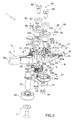
- Number 1 in Figures 1 and 2 illustrates as a whole a gripping assembly for a receptacle handling machine (not shown and known as such), in particular of the linear or rotary type, adapted to move between a closed configuration ( Figure 1 ) at which gripping assembly 1 is adapted to grip, in use, one receptacle, in particular one bottle 2 and an open configuration ( Figure 2 ) at which the gripping assembly is adapted to disengage from bottle 2.
- gripping assembly 1 being adapted to grip bottles 2, which, however, must be understood in a non-limiting manner as also other receptacles such as containers and pre-forms may be gripped by gripping assembly 1.
- gripping assembly 1 is adapted to grip bottles 2 made of base components, like glass, plastics, etc. and for any type of pourable product, such as carbonated liquids (e.g. sparkling water, soft drinks and beer), non-carbonated liquids (including still water, juices, teas, sport drinks, liquid cleaners, wine, etc), emulsions, suspensions, high viscosity liquids and beverages containing pulps.
- carbonated liquids e.g. sparkling water, soft drinks and beer
- non-carbonated liquids including still water, juices, teas, sport drinks, liquid cleaners, wine, etc
- emulsions e.g. sparkling water, soft drinks and beer
- non-carbonated liquids including still water, juices, teas, sport drinks, liquid cleaners, wine, etc
- emulsions e.g., suspensions, high viscosity liquids and beverages containing pulps.
- gripping assembly 1 is designed to be arranged in a manner known as such on a conveyor device (not shown and known as such) of the handling machine, in particular, gripping assembly 1 being supported by a support unit (not shown) of the conveyor device.
- the conveyor device being adapted to advance gripping assembly 1 along a path (not shown) through a receiving and a delivery station.
- the gripping assembly 1 is configured to receive one bottle 2 at the receiving station and to release bottle 2 at the delivery station. In particular, in use, gripping assembly 1 is controlled into the closed configuration for gripping bottle 2 during advancement between the receiving station and the delivery station.
- gripping assembly 1 comprises a main gripping arm 3 and an auxiliary gripping arm 4 configured to selectively grip in cooperation one bottle 2.
- each one of gripping arms 3 and 4 is adapted to rotate around one respective rotation axis A and B for moving gripping assembly 1 between the closed and the open configuration.
- axes A and B are parallel to each other, even more particularly axes A and B have a vertical orientation.
- Gripping assembly 1 further comprises:
- gripping arm 3 comprises a plastic base structure 8 and at least one magnet element 9, in particular magnet element 9 being encapsulated within plastic base structure 8.
- the magnet element 9 is configured to interact with a magnet assembly 10 of gripping assembly 1 for biasing gripping assembly 1 into its closed or open configuration, in the specific example shown into the closed configuration.
- Magnet assembly 10 is spaced apart from gripping arm 3.
- magnet assembly 10 and magnet element 9 defining biasing means 6.
- magnet assembly 10 comprises two magnets 10a being encapsulated in a plastic housing 10b.
- plastic base structure 8 comprises a cavity 13 designed to house magnet element 9.
- cavity 13 is arranged in a cavity section 14 of plastic base structure 8.
- cavity portion 14 being arranged at a first end portion 8a of plastic base structure 8.
- cavity 13 has a shape similar to the configuration of magnet element 9 so as to fully house magnet element 9, preferably without clearance.
- cavity 13 has a depth larger than the height of magnet element 9.
- Gripping arm 3 also comprises a cover portion 15 designed to cover magnet element 9 housed within cavity 13.
- gripping arm 3 has also a spacer element 16 arranged between magnet element 9 and cover portion 15.
- spacer element 16 has a platelike configuration and a shape similar to the upper profile of magnet element 9.
- plastic base structure 8 is produced during a first molding phase and cover portion 15 is obtained during a second molding phase after insertion of magnet element 9 and, preferably of spacer element 16, in particular for encapsulating magnet element 9.
- gripping arm 3, in particular plastic base structure 8 has a clamping section 17 adapted to, in use, at least partially engage with bottle 2, in particular with neck 2a of bottle 2.
- clamping section 17 has a semicircular indentation 18 configured to partially receive and encircle one side of neck 2a of bottle 2.
- Clamping section 17 is arranged at a second end portion 8b of plastic base structure 8 opposite of end portion 8a.
- plastic base structure 8 comprises at least one main reticular portion 19, preferably being arranged between end portions 8a and 8b, even more preferably arranged between cavity section 14 and clamping section 17.
- main reticular portion 19 is designed in such a manner to reduce the quantity of plastic material needed for producing plastic base structure 8 and to obtain a stability at least equal to the one obtainable with a pure solid design.
- main reticular portion 19 is designed to facilitate the cleaning and/or sterilization of gripping arm 3.
- plastic base structure 8 has at least one auxiliary reticular portion 20, in particular being arranged in the area of clamping section 17. Similar to main reticular portion 19 also auxiliary reticular portion 20 is designed in such a manner to reduce the quantity of plastic material needed and providing for at least the same stability compared to a pure solid workpiece. As well, auxiliary reticular portion 20 is similar to main reticular portion 19 designed to facilitate the cleaning and/or sterilization of gripping arm 3.
- gripping arm 3 has a z-shaped configuration, in particular defined by cavity section 14, main reticular portion 19 and clamping section 17.
- axis A is orthogonal to an upper and lower surface 21 and 22 of gripping arm 3, in particular of plastic base structure 8. More specifically, axis A is arranged at an intermediate section 23 of plastic base structure 8. More specifically, intermediate section 23 is arranged between end portions 8a and 8b, in particular between reticular portion 19 and clamping section 17, even more particular between reticular portions 19 and 20.
- gripping arm 4 comprises a clamping section 24 adapted to engage with bottle 2, in particular neck 2a. Furthermore, clamping section 24 is configured to cooperate with clamping section 17 for gripping bottle 2. In particular, clamping section 24 has a semicircular indentation 25 complementary to indentation 18 and clamping section 24 is configured to partially receive and encircle the other side of neck 2a of bottle 2.
- gripping arm 4 comprises a reticular portion 29, in particular provided in the area of clamping section 24.
- Reticular portion 26 is similar to auxiliary reticular portion 20 and is designed to provide for a stability which at least equals the one of a solid workpiece.
- reticular portion 26 is designed to facilitate the cleaning and/or sterilization of gripping assembly 1.
- axis B is arranged in the area of a first end portion 4a of gripping arm 4 and clamping section 24 is arranged in the area of a second end portion 4b of gripping arm 4 opposite of end portion 4a.
- axis B is orthogonal to an upper and lower surface portion 27 and a lower surface (not shown) of gripping arm 4.
- gripping arm 4 is of a plastic material. Even more preferentially gripping arm 4 is produced in a plastic molding process.
- coupling assembly 5 is adapted to transfer a rotation of gripping arm 3 around axis A to gripping arm 4 around axis B so that gripping arms 3 and 4 move synchronously. More specifically, gripping assembly 1 is configured in such a manner that through rotation of gripping arms 3 and 4 clamping sections 17 and 24 move away or approach each other. Even more specifically, gripping assembly 1 is configured so as that clamping sections 17 and 24 approach each other when being controlled from the open configuration to the closed configuration and clamping sections 17 and 24 withdraw from each other when being controlled from the closed configuration to the open configuration.
- gripping assembly 1 is configured to change the relative position of magnet element 9 and magnet assembly 10 to each other during a rotation of gripping arm 3.
- gripping assembly 1 is designed so that during a movement of gripping assembly 1 from the closed to the open configuration magnet element 9 is withdrawn from magnet assembly 10 and during a movement from the open to the closed configuration magnet element 9 approaches magnet assembly 10. Furthermore, in the closed configuration of magnet element 9 and magnet assembly 10 are arranged substantially parallel to each other.
- coupling assembly 5 comprises:
- actuation element 30 comprises first engagement means 32 and actuation element 31 has second engagement means 33, in particular engagement means 32 and 33 engaging and cooperating with each other.
- Actuation element 30 further comprises a base body 34 carrying engagement means 32.
- base body 34 has a substantially parallelepiped, even more particular a substantially rectangular parallelepiped shape.
- engagement means 32 comprise a plurality of tooth members 35 projecting away from base portion 35.
- gripping arm 3, in particular plastic base structure 8 comprises a housing recess 36 adapted to at least partially receive actuation element 31.
- housing recess 36 receives base body 34.
- housing recess 36 is arranged in the area of intermediate section 23.
- housing recess 36 is arranged between main reticular portion 19 and clamping section 17.
- housing recess 36 comprises an upper surface portion 21a and a lower surface portion 22a.
- upper surface 21 and lower surface 22 carry respectively upper surface portion 21a and lower surface portion 22a.
- upper surface portion 21a and lower surface portion 22a have a U-shaped profile and sandwich at least partially in between base body 34.
- gripping arm 3 also comprises fixing means 40 adapted to fix actuation element 30 with housing recess 36.
- fixing means 40 are configured to cooperate with a plurality of upper and lower holes 21b, 22b of gripping arm 3 and a plurality of through-holes 34a of actuation element 30.
- upper surface portion 21a comprises upper holes 21b and lower surface portion 22a comprises lower holes 22b.
- each upper hole 21b is coaxially arranged with one respective lower hole 22b.
- through-holes 34a are coaxially arranged with one respective upper and one respective lower hole 21b and 22b and are provided on base body 34.
- fixing means 40 comprise a plurality of pin members 41 each one extending through one respective through-hole 34a and the relative upper and lower holes 21b and 22b.
- each pin member 41 in particular having a mushroom-like shape, comprises a head portion 41a and a plain shank portion 41b.
- each respective head portion 41a contacts upper surface portion 21a and each respective plain shank portion 41b extends through one respective through-hole 34a and the relative upper and lower holes 21b and 22b. It must be noted, that each pin member 41 is arranged within the respective through-hole 34a in such a manner to be loosely housed within the respective through-hole 34a.
- fixing means 40 comprise securing means, in particular a screw assembly 42 configured to secure pin members 41.
- screw assembly 42 interacts with the respective head portions 41a of pin members 41.
- Screw assembly 42 comprises a bushing member 43 partially placed within a central hole 34b of actuation element 30, in particular of base body 34.
- bushing member 43 is placed coaxially with axis A and is arranged in such a manner to allow for synchronous rotation of actuation element 30 and of gripping arm 3 around axis A.
- bushing member 43 comprises a circular shoulder portion 43a interacting with pin members 41, in particular with the respective head portions 41a.
- the respective head portions 41a are at least partially sandwiched between shoulder portion 43a and upper surface portion 21a so as to secure pin members 41.
- Screw assembly 42 also comprises a securing element 44, in the specific case a threaded screw interacting with a lower portion 43b of bushing member 43 and with lower surface portion 22a for securing bushing member 43 and gripping arm 3, in particular plastic base structure 8 to one another in such a manner that gripping arm 3, in particular plastic base structure 8 is adapted to rotate around axis A.
- a securing element 44 in the specific case a threaded screw interacting with a lower portion 43b of bushing member 43 and with lower surface portion 22a for securing bushing member 43 and gripping arm 3, in particular plastic base structure 8 to one another in such a manner that gripping arm 3, in particular plastic base structure 8 is adapted to rotate around axis A.
- gripping arm 4 comprises a housing recess 45 adapted to at least partially receive actuation element 32.
- housing recess 45 is arranged in the area of first end portion 4a. Similar to housing recess 36, housing recess 45 comprises an upper surface portion 27a and a lower surface portion (not shown).
- upper surface 27 and lower surface 28 carry respectively upper surface portion 27a and the lower surface portion of housing recess 45.
- upper surface portion 27a comprises upper holes 27b and the lower surface portion of housing recess 45 comprises a plurality of lower holes (not shown). Thereby, each upper hole 27b is coaxially arranged with one respective lower hole of housing recess 45.
- actuation element 31 is similar to actuation element 30 the following description is limited to the differences between them, and using the same references, where possible, for identical or corresponding parts.
- the respective through-holes 34a are coaxially arranged with one respective upper hole 27b and one respective lower hole of housing recess 45.
- gripping arm 4 also comprises fixing means 46 adapted to fix actuation element 31 with housing recess 45.
- fixing means 46 are similar to fixing means 40 the following description is limited to the differences between them, and using the same references, where possible, for identical or corresponding parts.
- each pin member 41 of fixing means 46 extends through one respective through-hole 34a and the relative upper hole 27b and the relative lower hole of housing recess 45.
- the respective head portions 41a are at least partially sandwiched between shoulder portion 43a of the respective bushing member 43 and upper surface portion 27a.
- the respective bushing member 43 is placed coaxially with axis B and is arranged in such a manner to allow for rotation of synchronous actuation element 31 and gripping arm 4.
- the respective securing element 44 interacts with lower portion 43b of the respective bushing member 43 and with the lower surface portion of housing recess 45 for securing bushing member 43 and gripping arm 4 to one another in such a manner that gripping arm 4 is adapted to rotate around axis B.
- gripping arms 3 and 4 are connected one to another, in particular by means of a connecting member 47, in the example shown a plate element, in such a manner that engagement means 32 and 33 are and remain engaged to one another.
- gripping arms 3 and 4 are connected so as that the plurality of tooth 35 of engagement means 32 and the plurality of tooth 35 of engagement means 33 contact each other.
- connecting member 47 partially contacts lower surface 21 and the lower surface of gripping arm 4.
- connecting member 47 is arranged to contact lower surface portion 21a and the lower surface portion of housing recess 45.
- connecting member 47 is fastened by screw elements 44 in such a manner that gripping arm 3 and gripping arm 4 are adapted to rotate around axis A and B, respectively.
- gripping assembly 1 also comprises fastening means 48 adapted to fasten gripping assembly 1 to the relative support unit of the transfer device.
- fastening means 48 are configured to interact with screw assemblies 42 and the support unit.
- fastening means 48 comprise two screw elements 49, each one adapted to interact with the support unit and one respective screw assembly 42, in particular one respective bushing member 43, even more particular with one respective upper portion 43c of the relative bushing member 43 opposite of lower portion 43b.
- transferring means 7 are configured to interact with gripping arm 3 and to transfer the input force to a rotation of gripping arm 3 around axis A.
- transferring means 7 are configured to support counteraction of the force generated by biasing means 6.
- transferring means 7 comprise a cam follower 50 connected to gripping arm 3, in particular to plastic base structure 8. Transferring means 7 also comprise a pin or bolt member 51 carrying cam follower 51 and mounted to plastic base structure 8.
- cam follower 50 is adapted to cooperate with a cam profile (known as such and not shown) of the transferring device.
- cam follower 50 is configured to run along the cam profile.
- the cam profile is configured in a manner known as such to direct cam follower 50 from a relative first position (see Figure 1 ) to a relative second position (see Figure 2 ) with respect to magnet assembly 10. Movement of cam follower 50 from the first position to the second position actuates rotation of gripping arm 3, in particular plastic base structure 8 around axis A.
- cam follower 50 is directed from the relative second position to the relative first position as a result of the attractive forces between magnet element 9 and magnet assembly 10.
- the cam profile is designed to define the portions of the path of gripping assembly 1 at which gripping assembly 1 is in its closed and open configuration.
- the cam profile is designed in such a manner that the interaction of cam follower 50 and the cam profile provides for the input force along the portion or the portions of the path at which gripping assembly 1 is to be controlled into its open configuration.
- the cam profile is designed in such a manner that gripping assembly 1 is controlled into the open configuration at the receiving and the delivery station.
- gripping assembly 1 advances along the path through the receiving station and the delivery station. During advancement gripping assembly 1 grips one respective bottle 2 while advancing between the receiving station and the delivery station. In particular, gripping assembly 1 is controlled into its closed configuration while advancing from the receiving station to the delivery station. Furthermore, gripping assembly 1 is controlled into its open configuration at the receiving station and at the delivery station for respectively receiving and releasing bottle 2.
- gripping assembly 1 is moved from the closed configuration to the open configuration by actuating a rotation of gripping arm 3 around axis A.
- rotation of gripping arm 3 is actuated by a movement of cam follower 50 from the relative first position to the relative second position.
- the movement of cam follower 50 is determined by the cam profile.
- gripping assembly 1 is moved from the open configuration to the closed configuration due to the force exerted by biasing means 5.
- the interaction of cam follower 50 and the cam profile does not provide an input force anymore acting against the action of biasing means 5.
- the attractive forces of magnet assembly 10 and magnet element 9 lead to rotation of gripping arm 3 around axis A. This also leads to movement of cam follower 50 from the relative second position to the relative first position.
- the rotation of gripping arm 3 around axis A is transferred to gripping arm 4 so that gripping arm 4 rotates around axis B so that clamping sections 17 and 24 withdraw from each other.
- the transfer is obtained by coupling assembly 5, in particular by interaction of actuation element 30 with actuation element 31.
- the method for producing gripping assembly 1 is schematically shown in Figures 5a to 5e .
- the method comprises the following steps:
- a spacer element 16 is placed within cavity 13, in particular on top of magnet element 9.
- Spacer element 9 is adapted to reduce the thermal impact on magnet element 9 during the second molding phase. This is preferable, as a significant increase of the temperature of magnet element 9 leads to an alteration of the magnetic properties, in particular in a reduction of the magnetic field strength of magnet element 9. Otherwise, the choice of magnet element 9 in terms of the magnetic field strength must be made considering also the reduction of the magnetic field strength during the second molding phase.
- the first molding phase comprises the step of injecting molten plastic material (see Figure 5b ) into a main gripping arm mold 52.
- main gripping arm mold 52 (see Figure 5a ) having a mold cavity 52a designed to define the shape of plastic base structure 8. Furthermore, during the first molding phase an insert 53 defining cavity 13 within plastic base structure 8 is inserted in main gripping arm mold 52. In particular insert 53 is coupled to an upper cover of main gripping arm mold 52. Preferably, insert 53 has a shape similar to the shape of permanent magnet 9.
- insert 53 is removed from main gripping arm mold 52 (see Figure 5c ).
- the second molding phase comprises the step of injecting molten plastic material into main gripping element mold 52 (see Figure 5e ).
- cover portion 15 of gripping arm 4 is obtained.
- plastic base structure 8 remains in main gripping arm mold 52; i.e. plastic base structure 8 is not removed from and reinserted into main gripping arm mold 52.
- the plastic material used during the first and the second molding phases is the same.
- gripping arm 4 and actuation elements 30 and 31 are obtained from molding processes known as such and not further explained.
- gripping arm 4 and actuations elements 30 and 31 are produced from a plastic material identical to the one used during the first molding phase.
- the method further comprises an assembly phase during which gripping arms 3 and 4 are coupled to one another.
- the assembly phase comprises the steps of:
- connecting actuation element 30 to gripping arm 3 comprises the steps of:
- screw assembly 42 is connected to gripping arm 3 securing the relative pin members 41.
- bushing member 43 is partially placed within central hole 34b of actuation element 30, in particular in such a manner that the relative head portions 41a of the respective pin members 41 are partially sandwiched between shoulder portion 43a and upper surface 21, in particular upper surface portion 21a.
- securing element 44 is connected to bushing member 43, in particular lower portion 43a securing bushing member 43 and gripping arm 3, in particular plastic base structure 8 to one another. Furthermore, securing element 44 also secures connecting member 47 to gripping arms 3 and 4.
- Connecting actuation element 31 to gripping arm 4 is similar to connecting actuation element 30 to gripping arm 3 and the following description is limited to the differences between them.
- actuation element 31 is placed into housing recess 45 of gripping arm 4.
- Actuation element 31 is placed in such a manner that through-holes 34a are coaxially-aligned with one relative upper hole 27b and with one respective lower hole of housing recess 45 and one respective pin member 41 is guided through each one of through-holes 34a and the relative upper hole 27b and the respective lower hole of housing recess 45.
- the respective screw assembly 42 is connected to gripping arm 4 securing the relative pin members 41.
- bushing member 43 is partially placed within central hole 34b of actuation element 31, in particular in such a manner that the relative head portions 41a of the respective pin members 41 are partially sandwiched between shoulder portion 43a and upper surface 27, in particular upper surface portion 27a.
- gripping assembly 1 has an improved reliability as the interaction of magnet element 9 and magnet assembly 10 is not subject to any wear.
- a further advantage lies in the light-weight properties of gripping assembly 1 as mainly plastic material is used. This means that the motor chosen for driving rotation of the carousel to which gripping assemblies 1 are mounted to comes along with a reduced performance with respect to the ones used in the state-of-the-art. This reduces the purchasing costs and the operative costs, in particular due to a reduction in the power consumption.
- gripping assembly 1 As plastics material is used. This is further accentuated as gripping arm 3 comprises reticular portion 19 and 20 and gripping arm 4 has reticular portion 26. This further reduces the costs of production as less plastic material is required.
- Reticular portions 19, 20 and 26 also allow good characteristics in terms of hygienic design as the reticular portions allow for the cleaning and/or sterilizing agents running easily off.
- gripping assembly 1 is simple and fast. Gripping arm 3 is produced during two molding phases and favorably the workpiece remains in main gripping arm mold 52 during the two molding phases. This also provides for the advantage that magnet element 9 is encapsulated within plastic base structure 8. Relying on two molding phases further allows to avoid the presence of edges on upper surface 21 in the area of cavity section 14, in particular in correspondence with the contour of cover portion 15.
Priority Applications (1)
| Application Number | Priority Date | Filing Date | Title |
|---|---|---|---|
| EP16305688.0A EP3254996A1 (de) | 2016-06-10 | 2016-06-10 | Greifanordnung für eine behälterbehandlungsvorrichtung und verfahren zur herstellung einer greifanordnung für eine behälterbehandlungsvorrichtung |
Applications Claiming Priority (1)
| Application Number | Priority Date | Filing Date | Title |
|---|---|---|---|
| EP16305688.0A EP3254996A1 (de) | 2016-06-10 | 2016-06-10 | Greifanordnung für eine behälterbehandlungsvorrichtung und verfahren zur herstellung einer greifanordnung für eine behälterbehandlungsvorrichtung |
Publications (1)
| Publication Number | Publication Date |
|---|---|
| EP3254996A1 true EP3254996A1 (de) | 2017-12-13 |
Family
ID=56292642
Family Applications (1)
| Application Number | Title | Priority Date | Filing Date |
|---|---|---|---|
| EP16305688.0A Withdrawn EP3254996A1 (de) | 2016-06-10 | 2016-06-10 | Greifanordnung für eine behälterbehandlungsvorrichtung und verfahren zur herstellung einer greifanordnung für eine behälterbehandlungsvorrichtung |
Country Status (1)
| Country | Link |
|---|---|
| EP (1) | EP3254996A1 (de) |
Citations (8)
| Publication number | Priority date | Publication date | Assignee | Title |
|---|---|---|---|---|
| DE10140315A1 (de) * | 2001-08-16 | 2003-03-06 | Tetra Laval Holdings & Finance | Greifer zum Haltern und Bewegen von Hohlkörpern |
| US20080272609A1 (en) * | 2005-02-23 | 2008-11-06 | Krones Ag | Claw for a Container Transporting System |
| EP1868746B1 (de) | 2005-03-30 | 2009-05-06 | Krones AG | Klammer zum halten von gefässen |
| EP2316738A2 (de) * | 2009-11-02 | 2011-05-04 | Leo Bühler | Stretch-Sleeve-Etikettieren |
| US20110147166A1 (en) * | 2008-11-03 | 2011-06-23 | Khs Gmbh | Clip for capturing bottle necks, particularly of pet bottles |
| EP2293998B1 (de) | 2008-07-10 | 2012-10-24 | Krones AG | Klammergreifer |
| WO2015048642A1 (en) * | 2013-09-30 | 2015-04-02 | Laitram, L.L.C. | Magnetic conveyor belt module |
| EP2881345A1 (de) * | 2013-12-05 | 2015-06-10 | Sidel S.p.a. Con Socio Unico | Leitung zur Förderung von Behältern, insbesondere Flaschen |
-
2016
- 2016-06-10 EP EP16305688.0A patent/EP3254996A1/de not_active Withdrawn
Patent Citations (8)
| Publication number | Priority date | Publication date | Assignee | Title |
|---|---|---|---|---|
| DE10140315A1 (de) * | 2001-08-16 | 2003-03-06 | Tetra Laval Holdings & Finance | Greifer zum Haltern und Bewegen von Hohlkörpern |
| US20080272609A1 (en) * | 2005-02-23 | 2008-11-06 | Krones Ag | Claw for a Container Transporting System |
| EP1868746B1 (de) | 2005-03-30 | 2009-05-06 | Krones AG | Klammer zum halten von gefässen |
| EP2293998B1 (de) | 2008-07-10 | 2012-10-24 | Krones AG | Klammergreifer |
| US20110147166A1 (en) * | 2008-11-03 | 2011-06-23 | Khs Gmbh | Clip for capturing bottle necks, particularly of pet bottles |
| EP2316738A2 (de) * | 2009-11-02 | 2011-05-04 | Leo Bühler | Stretch-Sleeve-Etikettieren |
| WO2015048642A1 (en) * | 2013-09-30 | 2015-04-02 | Laitram, L.L.C. | Magnetic conveyor belt module |
| EP2881345A1 (de) * | 2013-12-05 | 2015-06-10 | Sidel S.p.a. Con Socio Unico | Leitung zur Förderung von Behältern, insbesondere Flaschen |
Similar Documents
| Publication | Publication Date | Title |
|---|---|---|
| EP2938545B1 (de) | Maschine und verfahren zur befüllung von behältern | |
| US9102479B2 (en) | Gripper arm with integral spring bar for grasping, holding and guiding bottle-like containers | |
| EP2473411B1 (de) | Etikettiervorrichtung | |
| CN106348235B (zh) | 用于灌装容器的机器和方法 | |
| CN109863110B (zh) | 用于在容器或瓶子上施放盖子的封盖头 | |
| CN105314577B (zh) | 用于灌注容器和给容器加盖的设备 | |
| EP2889229A1 (de) | Maschine zum Bearbeiten von Behältern mit verbesserter Kontrollarchitektur | |
| EP3254996A1 (de) | Greifanordnung für eine behälterbehandlungsvorrichtung und verfahren zur herstellung einer greifanordnung für eine behälterbehandlungsvorrichtung | |
| US9388032B2 (en) | Magnetic cap ejector in a capper | |
| EP2792634B1 (de) | Positionssteuerungssystem für eine Artikelhandhabungsmaschine und zugehöriges Verfahren | |
| EP2546163B1 (de) | Etikettierbetrieb als Handhabung für eine Anwendung mit gekapselter Behälter | |
| EP3162721A1 (de) | Vorrichtung zur handhabung von behältern | |
| EP1273551B1 (de) | Verschliesseinrichtung mit einem Verschliesskopf | |
| EP3106402A1 (de) | Prozess und vorrichtung zum verschliessen und bedrucken/etikettieren eines behälters | |
| EP4085020A1 (de) | Befülleinheit und füllmaschine mit einer befülleinheit zum befüllen von behältern | |
| EP3481763B1 (de) | Greifer mit verriegelungshals | |
| EP3991757A1 (de) | Sterilisationsvorrichtung und verfahren zum sterilisieren von behälterverschlüssen | |
| WO2021136581A1 (en) | Filling unit for filling receptacles | |
| CN102149625B (zh) | 用于对容器进行保持的可伸缩保持装置和装备有此种保持装置的容器处理设备 | |
| WO2023117062A1 (en) | Magnetic gripper for handling containers adapted to contain a pourable product | |
| US10273135B2 (en) | Machine for filling containers | |
| EP4169857A1 (de) | Greifer zum handhaben von behältern, die ein rieselfähiges produkt enthalten | |
| EP4043371A1 (de) | Passiver greifer, fördervorrichtung mit einem passiven greifer und füllmaschine mit einer fördervorrichtung mit einem passiven greifer | |
| EP3254993A1 (de) | Artikelfördervorrichtung, verfahren zum betrieb solch einer artikelfördervorrichtung und artikelhandhabungsvorrichtung mit mindestens einer solchen artikelfördervorrichtung | |
| CN203998870U (zh) | 一种玻璃罐的封口装置 |
Legal Events
| Date | Code | Title | Description |
|---|---|---|---|
| PUAI | Public reference made under article 153(3) epc to a published international application that has entered the european phase |
Free format text: ORIGINAL CODE: 0009012 |
|
| AK | Designated contracting states |
Kind code of ref document: A1 Designated state(s): AL AT BE BG CH CY CZ DE DK EE ES FI FR GB GR HR HU IE IS IT LI LT LU LV MC MK MT NL NO PL PT RO RS SE SI SK SM TR |
|
| AX | Request for extension of the european patent |
Extension state: BA ME |
|
| STAA | Information on the status of an ep patent application or granted ep patent |
Free format text: STATUS: THE APPLICATION IS DEEMED TO BE WITHDRAWN |
|
| 18D | Application deemed to be withdrawn |
Effective date: 20180614 |