EP3254792B1 - A method for sawing edges of a wood laminate panel and an arrangement for the same - Google Patents
A method for sawing edges of a wood laminate panel and an arrangement for the same Download PDFInfo
- Publication number
- EP3254792B1 EP3254792B1 EP16397520.4A EP16397520A EP3254792B1 EP 3254792 B1 EP3254792 B1 EP 3254792B1 EP 16397520 A EP16397520 A EP 16397520A EP 3254792 B1 EP3254792 B1 EP 3254792B1
- Authority
- EP
- European Patent Office
- Prior art keywords
- wood laminate
- laminate panel
- finished
- panel
- unfinished
- Prior art date
- Legal status (The legal status is an assumption and is not a legal conclusion. Google has not performed a legal analysis and makes no representation as to the accuracy of the status listed.)
- Not-in-force
Links
Images


Classifications
-
- B—PERFORMING OPERATIONS; TRANSPORTING
- B27—WORKING OR PRESERVING WOOD OR SIMILAR MATERIAL; NAILING OR STAPLING MACHINES IN GENERAL
- B27B—SAWS FOR WOOD OR SIMILAR MATERIAL; COMPONENTS OR ACCESSORIES THEREFOR
- B27B5/00—Sawing machines working with circular or cylindrical saw blades; Components or equipment therefor
- B27B5/02—Sawing machines working with circular or cylindrical saw blades; Components or equipment therefor characterised by a special purpose only
- B27B5/04—Sawing machines working with circular or cylindrical saw blades; Components or equipment therefor characterised by a special purpose only for edge trimming
-
- B—PERFORMING OPERATIONS; TRANSPORTING
- B23—MACHINE TOOLS; METAL-WORKING NOT OTHERWISE PROVIDED FOR
- B23D—PLANING; SLOTTING; SHEARING; BROACHING; SAWING; FILING; SCRAPING; LIKE OPERATIONS FOR WORKING METAL BY REMOVING MATERIAL, NOT OTHERWISE PROVIDED FOR
- B23D59/00—Accessories specially designed for sawing machines or sawing devices
- B23D59/001—Measuring or control devices, e.g. for automatic control of work feed pressure on band saw blade
Definitions
- the invention relates to arrangements and methods for automatically sawing edges of a wood laminate panel, as per the preamble of claims 11 and 1 respectively.
- An example of such an arrangement and method is disclosed by US 3 922 940 A .
- Wood laminate panels such as plywood panels, are generally manufactured by laying subsequent layers of the panel on top of each other, arranging some adhesive in between the layers, and hot-pressing the stack of layers to form a wood laminate panel.
- the side surfaces of such a panel are unfinished.
- edges of the wood laminate panel are sawn off the panel to form finished side surfaces.
- the width of the defected areas near the unfinished surfaces is not necessary the same from a panel to another panel. Therefore, the predetermined amount may not be sufficient for every panel. When the width is not sufficient, the quality of the finished panel is not sufficient, and the panel becomes wasted. Thus, the aforementioned method for finishing the panels may result in a producing some waste.
- An object of the present invention is to present a method and an arrangement, by which the amount of waste can be reduced. It has been found that by imaging optically a finished side surface, a width of a defected area can be determined for each panel by using such images. Correspondingly, the panel can be moved relative to a saw by such an amount that the defected area, and essentially only the defected area, can be sawn off the panel to finish the panel. In this way, by sawing a panel specific amount off from at least an edge of the panel, the finished panel will more likely full fill the quality requirements, which reduces the amount of waste.
- the invention is disclosed in more specific terms in the independent claim 1. A corresponding arrangement for finishing the panel is disclosed in the independent claim 11.
- two opposite finished side surfaces are optically imaged and the information is used to determine a width of a defected area of the panel. This information is used to saw a panel-specific amount of defected edge off from the panel.
- a main surface, such as a top surface, of the panel is optically imaged to obtain information indicative of the shape of the panel; and the information indicative of the shape of the panel is also used to determine the width of the defected area of the panel.
- a side stopper is moved relative to a saw, by using the width of the defected area.
- the wood laminate panel can be aligned with the saw by moving the panel towards the side stopper until the panel makes a contact with the side stopper.
- the method is applied to finish (i.e. saw the edges off from) a plywood panel.
- the invention relates to a method for finishing a wood laminate panel 300.
- Finishing in this context means sawing four boundaries of a wood laminate panel.
- the wood laminate panel 300 has the shape of a substantially rectangular panel, and all the four side surfaces of the panel are finished by sawing to obtain a rectangular finished panel.
- the term wood laminate panel 300 refers to an object having a length L, a width W, and a thickness T, wherein the thickness T is smaller than the smaller of the length L and the width W.
- the length L is perpendicular to the width W.
- the thickness T is perpendicular to the length L and the width W.
- the direction Sx is parallel to length or width
- the direction Sz is parallel to thickness
- the direction Sy is perpendicular to both Sx and Sz.
- the wood laminate panel 300 comprises a first layer 110 comprising wood and a second layer 120 comprising wood.
- the first and the second layers 110, 120 are arranged relative to each other in the direction Sz of the thickness T of the wood laminate panel 300. The centres of these layers are arranged a distance apart from each other in the direction of the thickness T. The layers may be arranged next to each other in the direction of thickness of the wood laminate panel.
- the wood laminate panel 300 comprises adhesive 195 in between each two neighbouring layers (110, 120, 130 ,140, 150) comprising wood, and thus also in between the first layer 110 and the second layer 120.
- the panel 300 may comprise further layers 130, 140, 150 comprising wood.
- the other layers (130, 140, 150) comprising wood may be arranged in between the first 110 and the second layer 120. In general, none, only one, or both of the first 110 and the second 120 layers may be a surface layer of the wood laminate panel.
- Examples of a wood laminate panel 300 include plywood, laminated timber, cross laminated timber, and oriented standard board.
- the invention is explained using plywood as an example. Even if the method can be applied also to the other types of laminated wood panels, application of the method to plywood has certain technical advantages, as will be detailed below.
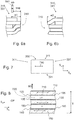
- Figs. 2 and 3 show, in a top view, a plywood panel 300 before the sides have been finished.
- the panel has four sides. Two opposite of the sides are hereinafter referred to as the side surfaces 310, 320 and the other two opposite of the sides are hereinafter referred to the end surfaces 330, 340.
- the plywood panel has a first unfinished side surface 310 having a first surface normal N1 substantially parallel to the length L or the width W.
- the term substantially parallel means that the first surface normal is parallel or forms an angle of at most 15 degrees with the length or the width.
- the plywood panel is not necessarily rectangular, even if it typically comprises only four sides.
- the plywood panel 300 has also a second unfinished side surface 320 opposite to the first unfinished side surface 310, whereby the second unfinished side surface has a surface normal reverse or substantially reverse to the first surface normal N1.
- the term substantially reverse may refer e.g. to an angle of from 150 to 210 degrees to the first surface normal N1.
- the plywood panel 300 has also a first unfinished end surface 330 having a second surface normal N2 substantially parallel to the width W or the length L, respectively. Substantially parallel means an angle of at most 15 degrees or no angle.
- first unfinished end surface 330 has a second surface normal N2, which is substantially perpendicular to the thickness T of the panel and the first surface normal N1. Substantially perpendicular here in the meaning that the second surface normal is perpendicular or forms an angle of from 75 to 105 degrees with the first surface normal N1.
- the plywood panel has also a second unfinished end surface 340 opposite to the first end surface 330, whereby the second unfinished end surface 340 has a surface normal reverse to the second surface normal N2. For definition of substantially reverse, see above.
- the plywood panel 300 also has two main surfaces 301, i.e. a top surface and a bottom surface, wherein the surface normals of the main surfaces 301 are parallel to the thickness T of the panel 300.
- the side (310, 320) and end (330, 340) surfaces are, at a point of time, unfinished.
- the layers 110, 120 of the plywood panel 300 are better aligned near the first unfinished side surface 310 than near either of the second surfaces (320, 340): the second unfinished side surface 320, or the second 340 unfinished end surface.
- the layers 110, 120 of the plywood panel 300 are better aligned also near the first unfinished end surface 330 than near either of the second surfaces (320, 340).
- a plywood panel 300 is manufactured by manufacturing the first 110 and second 120 layers of the wood laminated panel, aligning (i.e. positioning) an edge 111a of the first layer 110 such that the edge 111a of the first layer 110 makes a contact with a first side aligner 200 and aligning (i.e. positioning) an edge 121a of the second layer 120 such that the edge 121a of the second layer 120 makes a contact with the first side aligner 200.
- a corresponding arrangement may comprise a conveyor 210 configured to move the layers 110, 120 towards the first side aligner 200. Therefore, these edges 111a, 121a become reasonably well aligned relative to each other.
- the layers may have been aligned, from another edge (111b, 121b), to a second side aligner 205.
- the first unfinished side surface 310 of the wood laminate panel comprises [a] the edge 111a of the first layer that has been aligned with the first side aligner 200 and [b] the edge 121a of the second layer that has been aligned with the first side aligner 200.
- the layers of the plywood panel are reasonable well aligned at the first unfinished side surface 310 of the plywood panel 300.
- the first unfinished end surface 330 of the wood laminate panel comprises [a] the other edge 111b of the first layer 110 that has been aligned with the second side aligner 205 and [b] the other edge 121b of the second layer 120 that has been aligned with the second side aligner 205.
- the layers of the plywood panel are reasonable well aligned at the first unfinished end surface 330 of the plywood panel 300.
- the edge 111a of the first layer 110 can be aligned to a side alignment position 200 e.g. by using a conveyor and a photodetector such that the first layer 110 is moved only until the photodetector detects the edge 111a of the first layer 110 at the side alignment position.
- the edge 121a of the second layer 120 can be aligned to the side alignment position 200 e.g. by using a conveyor and the photodetector or another photodetector such that the second layer is moved only until the photodetector detects the edge 121a of the second layer at the side alignment position 200.
- the first unfinished side surface 310 of the wood laminate panel comprises the edge 111a of the first layer and the edge 121a of the second layer. This applies also to the other edges 111b and 121b and the first end surface 330, whereby the other edges 111b, 121b can be aligned to an end alignment position 205.
- the layers 110, 120, 130 may be stacked in such a way that some of the layers are moved onto the stack from one direction, and some of the layers are moved onto the stack from another, perpendicular, direction. Also in this way, the first side surface 310 and the first end surface 330 of the plywood panel become reasonably well aligned. Typically in the field, the first surfaces are called "hard", because the reasonably well alignment makes the surfaces hard.
- FIGS. 4 and 5 show a preferable arrangement for sawing edges of a wood laminate panel 300.
- a first end piece 332 comprising the first unfinished end surface 330 is sawn from the wood laminate panel 300.
- the first end piece 332 may be sawn along the sawing line 431.
- a first finished end surface 331 is formed to the wood laminate panel 300.
- a corresponding arrangement comprises a first primary saw 511 configured to saw from a wood laminate panel 300 a first end piece 332 comprising a first unfinished end surface 330 of the wood laminate panel 300, to form a first finished end surface 331 to the wood laminate panel 300.
- the first end piece 332 is sawn in such a way that the surface normal of the first finished end surface 331 defines the direction of the length L or the width W of the wood laminate panel 300. More precisely, provided that the first unfinished end surface 330 has a second surface normal N2 substantially parallel to the length L of the wood laminate panel 300, the surface normal of the first finished end surface 331 is parallel to the length L of the wood laminate panel 300 (not shown). Correspondingly, provided that the first unfinished end surface 330 has a second surface normal N2 substantially parallel to the width W of the wood laminate panel (as in Fig. 2 ), the surface normal of the first finished end surface 331 is parallel to the width W of the wood laminate panel 300 (see Fig. 4 ).
- the surface normal of the first finished end surface 331 is substantially parallel to the second surface normal N2 of the first unfinished end surface 330.
- the term substantially parallel means no angle or an angle of at most 15 degrees.
- a second end piece 342 comprising the second unfinished end surface 340 is sawn from the wood laminate panel 300, thereby forming a second finished end surface 341 to the wood laminate panel 300.
- the second end piece 342 may be sawn in such a way that the second finished end surface 341 is opposite to the first finished end surface 331.
- An arrangement may comprise a second primary saw 512 for the purpose.
- At least part of the first finished end surface 331 is imaged.
- at least such a part of the first finished end surface 331, that is close to (i.e. near) the first unfinished side surface 310 is imaged.
- the term "close” herein refers to such a part of the surface, of which distance from the unfinished side surface 310 is at most 200 mm, at most 100 mm, or at most 50 mm.
- at least such a part of the first finished end surface 331, that intersects with the first unfinished side surface 310 is imaged. An example of such an image is shown in Fig. 6a .
- the whole first finished end surface 331 is imaged.
- Imaging may be made with an optical detector 531.
- the optical detector 531 is an optoelectronic detector 531, such as a digital camera 531, such as a line camera 531.
- first information 610 ( Fig. 5 ) indicative of the structure of the wood laminate panel 300 is received.
- a corresponding arrangement comprises a first optical detector 531 configured to image at least the part of the first finished end surface 331 of the wood laminate panel 300 as discussed in context with the method.
- the first optical detector 531 is arranged to give first information 610 indicative of the structure of the wood laminate panel 300.
- a corresponding arrangement may comprise a light source 521 configured to lighten the first finished end surface 331 of the wood laminate panel 300.
- the light source 521 may be needed in on-line measurements, wherein the imaging must be done relatively rapidly.
- the method comprises imaging at least part of the second finished end surface 341.
- at least such a part of the second finished end surface 341, that is close to the first unfinished side surface 310 is imaged.
- at least such a part of the second finished end surface 341, that intersects with the first unfinished side surface 310 is imaged.
- the whole second finished end surface is imaged 341. Imaging may be done as discussed in connection with imaging the first finished end surface 331. An example of such an image is shown in Fig. 6b .
- second information 620 ( Fig. 5 ) indicative of the structure of the wood laminate panel 300 is received.
- a corresponding arrangement comprises a second optical detector 532 configured to image at least the part of the second finished end surface 341 of the wood laminate panel 300 as discussed in context with the method. Moreover, the second optical detector 532 is arranged to give second information 620 indicative of the structure of the wood laminate panel 300.
- a corresponding arrangement may comprise a light source 522 configured to lighten the second finished end surface 341 of the wood laminate panel 300. The light source 522 may be needed in on-line measurements, wherein the imaging must be done relatively rapidly.
- the width w1, w2 of a defected area 315 near the first unfinished side surface 310 of the wood laminate panel 300 is determined.
- the width w1, w2 of the defected area 315 is determined automatically.
- the width w1, w2 of the defected area 315 is determined in a control unit 600.
- a corresponding arrangement comprises a control unit 600 that is configured to determine information indicative of a width w1, w2 of the defected area 315 near the first unfinished side surface 310 of the wood laminate panel 300 by using the first information 610 indicative of the structure of the wood laminate panel 300 and the second information 620 indicative of the structure of the wood laminate panel 300.
- the defected area 315 does not necessarily comprise all the defects.
- the width w1, w2 of the defected area 315 may be defined so that the resulting finished side surface 311 will have a sufficiently high quality.
- the wood laminate panel comprises a defected area 315 near the first unfinished side surface 310.
- the aim of finishing the first side surface 310 of the panel 300 is, in particular, to saw away from the panel such defects at this (and other) edges, that a finished panel with reasonably high quality edges is obtained.
- the structure of the panel 300 near the first unfinished side surface 310 can be observed. From the image, such as the image of Fig. 6a , the width w1 of the defected area 315 can be determined.
- first unfinished end surface 330 In contrast, before finishing the first unfinished end surface 330, defects near and on the first unfinished end surface 330 prevent the visual observation good area of the panel and within the panel, in a direction parallel to a direction of the first unfinished end surface 330. Therefore, the first 330 and second 340 end surfaces are first finished, and only thereafter, the first 331 and second 341 finished end surfaces are imaged to obtain the first 610 and second 620 information.
- the width w1, w2 of the defected area it is possible to optimize the quality of the first finished side surface 311 by selecting the width of the a first side piece 312 to be sawn, as discussed in more detail below.
- the widths of the first side pieces 312 sawn off from panels 300 correlate positively with the widths w1, w2 of the defected areas 315 of those panels 300.
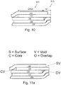
- Figures 11a to 11d show examples of defects of a wood laminate panel.
- the defect can be located on the surface (denoted by S in the figures 11a-11d ) or in the core (denoted by C in the figures 11a-11d ).
- the type of defect may be e.g. a void (denoted by V in the figures 11a-11d ) or an overlap (denoted by O in the figures 11a-11d ).
- These classifications result in four different types of defects: surface void (SV), surface overlap (SO), core void (CV) or core overlap (CO).
- a void is a result of a too narrow layer, whereby a layer is missing at a point of the plywood panel.
- Voids are shown in Figs.
- an embodiment comprises imaging at least such a part of the first finished end surface 331 and the second finished end surface 341 that are near the first unfinished side surface 310, thereby receiving first information 610 and second information 620 indicative of the structure of the wood laminate panel 300; and determining, using the first 610 and second 620 information indicative of the structure of the wood laminate panel 300, information indicative of a width (w1, w2) of a defected area 315 near the first unfinished side surface 310 of the wood laminate panel 300.
- determining the information indicative of a width (w1, w2) of a defected area 315 near the first unfinished side surface 310 of the wood laminate panel 300 comprises determining, by using the first 610 and second 620 information indicative of the structure of the wood laminate panel 300, that the defected area comprises a defect that belongs to the group of a surface void, a surface overlap, a core void, and a core overlap. In particular the voids are most clearly visible in the images.
- an embodiment comprises determining, by using the first 610 and second 620 information indicative of the structure of the wood laminate panel 300, that the defected area comprises a void.
- An embodiment comprises determining, by using the first 610 and second 620 information indicative of the structure of the wood laminate panel 300, that the defected area comprises a surface void or a core void.
- An embodiment when applied in sequence to multiple panels, comprises determining, by using the information indicative of the structures of the wood laminate panels, that defected areas of the panels, in combination, comprise a surface void, a surface overlap, a core void, and a core overlap.
- control unit 600 of the arrangement is configured to determine information indicative of a width (w1, w2) of the defected area 315 near the first unfinished side surface 310 of the wood laminate panel 300 using the first 610 and second 620 information indicative of the structure of the wood laminate panel 300.
- control unit 600 is configured to determine that the defected area comprises a defect that belongs to the group of a surface void, a surface overlap, a core void, and a core overlap.
- control unit 600 is configured to receive information indicative of the structures of the wood laminate panels, and the control unit is configured to determine that a defect is a surface void, another a defect is a surface overlap, another a defect is a core void, and another a defect is a core overlap.
- defects are known to occur, these including fallen off knot, hole, open split, chip, open seam, cross split, linear wormhole, missing patch, and missing veneer.
- a defect of any of these types may be detected from the images.
- the wood laminate panel 300 is transferred relative to a saw 541, such as a first secondary saw 541, by using the width w1, w2 of the defected area 315 near the first unfinished side surface 310 of the wood laminate panel 300, in such a way that the defected area 315 can be sawn by the saw 541.
- a saw 541 such as a first secondary saw 541
- the panel 300 is moved in that way automatically.
- the panel is moved in such a way that the control unit 600 is configured control the movement so that the defected area 315 can be sawn by the saw 541.
- the panel 300 is moved in such a way that by sawing the defected area 315, a first side piece 312 comprising the defected area 315 is sawn. Moreover, preferably, the first side piece 312 is essentially as large as the defected area 315.
- a corresponding arrangement comprises a first secondary saw 541 configured to saw from the wood laminate panel 300 a first side piece 312 comprising a first unfinished side surface 310 of the wood laminate panel and a defected area 315. The arrangement further comprises means for moving the panel 300 relative to the first secondary saw 541.
- the aforementioned "defected area” does not necessarily comprise all the defects.
- the defected area comprises such defects that the quality of the finished first side surface 311 will be at an acceptable level.
- the arrangement may comprise a conveyor for moving the wood laminate panel 300 relative to the first secondary saw 541.
- the conveyor may be e.g. a roll conveyor or a belt conveyor.
- the arrangement may comprise means 571 for moving the saw 541 relative to the panel 300.
- the panel 300 is moved with a conveyor 561 towards a side stopper 552, until the panel makes a contact with the side stopper 552.
- the position of the side stopper 552 may be adjusted with means 553 for moving the side stopper 552.
- control unit 600 is configured to control means (561, 553, 571) for moving the wood laminate panel 300 and/or the first secondary saw 541 relative to each other, by using the width w1, w2 of the defected area 315 near the first unfinished side surface 310 of the wood laminate panel 300.
- a first side piece 312 comprising the defected area 315 and the first unfinished side surface 310 is sawn from the wood laminate panel 300.
- a first finished side surface 311 is formed to the wood laminate panel 300.
- the first side piece 312 is sawn in such a way that the surface normal of the first finished side surface 311 defines the width W or the length L of the wood laminate panel 300. More precisely, provided that the first unfinished side surface 310 has a first surface normal substantially parallel to the length L of the wood laminate panel, the surface normal of the first finished side surface 311 is parallel to the length L of the wood laminate panel (see Figs. 2 and 4 ).
- the first unfinished side surface 310 has a first surface normal N1 substantially parallel to the width W of the wood laminate panel
- the surface normal of the first finished side surface 311 is parallel to the width W of the wood laminate panel.
- the surface normal of the first finished side surface 311 is substantially parallel to the first surface normal N1 of the first unfinished side surface 310.
- substantially parallel means no angle or an angle of at most 15 degrees.
- the length of the unfinished panel 300 is somewhat larger than the length of the finished panel 300.
- the direction of length is, in this description, defined as being parallel to a surface normal of a finished surface (i.e. a surface of the finished panel). This applies also to the width of the panel mutatis mutandis.
- the width w1, w2 of the defected area 315 extends in the direction of the first surface normal N1 (see Figs. 2 and 3 ).
- the imaging is done from the first 331 and second 341 finished end surfaces both having a surface normal substantially perpendicular to the thickness T of the wood laminate panel 300 and substantially perpendicular to the first surface normal N1.
- a first width w1 of the defected area 315 can be determined.
- a second width w2 of the defected area 315 can be determined.
- the information indicative of the width of the defected area may correspond e.g. to the maximum of the first width w1 and the second width w2.
- a corresponding first side piece 312 can be sawn from the panel 300 to finish the first side surface 310.
- the width w1 or w2 itself may be determined such that the quality of the first finished side surface 311 will meet a predetermined limit, at least near the first finished end surface 331 or the second finished end surface 341, respectively.
- the first finished side surface 311 may comprise core voids (CV, Fig. 11c ) wherein the depth of the core voids on the first finished side surface 311 is at most 5 mm.
- the depth of the core voids on the first finished side surface 311 is at most 5 mm.
- at most three core layers of the first finished side surface 311 comprise core voids.
- the aforementioned method may be used to finish a panel that will be later coated. Then, after the coating, the panel may be re-finished, i.e. the edges may be sawn again. In the process of re-finishing, e.g. from 1 mm to 100 mm may be sawn from each edge. The process of re-finishing may be taken into account already when determining the width w1, w2 of the defected area. For example, if it is known that an amount (e.g. 5 mm) will be sawn in the re-finishing process, the widths w1, w2 may be decreased by the same amount.
- an amount e.g. 5 mm
- a width of the first side piece 312 may be e.g. from 0.5 mm to 200 mm.
- a second side piece 322 comprising the second unfinished side surface 320 is sawn from the wood laminate panel 300 to form a second finished side surface 321 to the wood laminate panel 300.
- the second side piece 322 is sawn after said transferring the panel 300 relative to the saw 541.
- An arrangement may comprise a second secondary saw 542 for the purpose.
- the second side piece 322 may be sawn in such a way that the second finished side surface 321 is opposite to the first finished side surface 311.
- the method further comprises sawing the wood laminate panel 300 to at least two pieces of wood laminate panel, each piece of wood laminate panel having a first finished side surface, a second finished side surface, a first finished end surface, and a second finished end surface.
- a large panel can be saw to at least two smaller finished pieces of wood laminate panels.
- the panel may be sawn in such a way e.g. by a further saw 543.
- the corresponding arrangement comprises at least a further secondary saw 543, configured to saw the wood laminate panel 300 to at least two pieces of wood laminate panel, each piece of wood laminate panel having a first finished side surface, a second finished side surface, a first finished end surface, and a second finished end surface.
- the wood laminate panel comprises also a main surface 301, such as a top surface 301.
- an embodiment of the method comprises imaging the main surface 301 to receive information 630 indicative of the shape of the wood laminate panel 300.
- the method further comprise determining, using the also the information 630 indicative of the shape of the wood laminate panel 300, the information indicative of the width w1, w2 of a defected area 315 near the first unfinished side surface 310 of the wood laminate panel 300.
- a corresponding arrangement comprises a further optical detector 533 configured to image the main surface 301 of the wood laminate panel 300.
- the further optical detector 533 is configured to give information 630 indicative of the shape of the wood laminate panel 300.
- the control unit 600 is configured to determine the width w1, w2 of the defected area 315 by using also the information 630 indicative of the shape of the wood laminate panel 300.
- the shape of the panel 300 may refer e.g. to the skewness of the (unfinished) wood laminate panel 300. Skewness may be related e.g. to the value of a maximum angle of a tetragon, such as a maximum angle of a parallelogram.
- the shape of the unfinished wood laminate panel may be, in the alternative, irregular quadrilateral. By finishing, a rectangular shape is obtained, as detailed above.
- the wood laminate panel 300 typically comprises at least three layers (110, 120, 130) comprising wood.
- a layer (110, 120, 130, 140, 150) comprises at least one wooden veneer 112 having been manufactured by one of rotary cutting, flat slicing, quarter slicing, half-round slicing, rift cutting, and sawing.
- all such layers that comprise wood comprises a wooden veneer having been manufactured by one of rotary cutting, flat slicing, quarter slicing, half-round slicing, rift cutting, and sawing.
- Rotary cutting may also be referred to as rotary peeling, turning, or rotary turning.
- a layer 110 may comprise more than one veneers 112. However, in typical plywood panel, each layer 110 comprises only one wooden veneer 112. Such a structure improves the determinability of the width w1, w2 of the defected area 315.
- a plywood panel 300 typically comprises phenol resin or polyphenol as the adhesive 195 in between the layers comprising wood.
- the adhesive may be selected from the group of phenolic resin, phenol-formaldehyde, urea-melamine, melamine formaldehyde, resorcinol, thermoplastics, and a lignin-based adhesive.
- lignin-based adhesive refers to an aqueous binder composition comprising at least some polymerizable substance and some crosslinking agent, wherein at least 20 weight-% of the polymerizable substance originates from lignin.
- the crosslinking agent is selected from the group of aldehydes.
- the crosslinking agent is selected from the group consisting of an aromatic aldehyde, glyoxal, furfuryl alcohol, caprolactam, and glycol compounds.
- the crosslinking agent is formaldehyde or paraformaldehyde or a combination thereof. More specific examples of lignin-based adhesives usable in the present invention can be found from the publication WO2015/114195 .
- Thermoplastics refer to materials that become pliable or moldable above a deflection temperature (i.e. melting point) and solidify upon cooling.
- the deflection temperature of the thermoplastic may be e.g. from 80 °C to 200 °C, such as from 120 °C to 170°C.
- a layer 110, 120 of the panel 300 may comprise softwood and/or a layer 120, 110 of the panel 300 may comprise hardwood. It is possible that a top layer (and a bottom layer) comprises hardwood, while other layers comprise softwood. Preferably, a layer 110, 120 of the panel 300 comprises softwood, such as spruce, pine, or cedar.
- the thickness of a layer 110, 120 comprising wood is preferably from 0.1 mm to 4.0 mm, such as from 0.2 mm to 4.0 mm, such as from 1.2 mm to 3.6 mm, such as 2.6 mm or 3.2 mm.
- the number of layers 110, 120 comprising wood of the panel 300 is at least 3, or at least 5.
- the wood laminate panel 300 is symmetric about a central plane CP (see Fig. 8 ) having a surface normal parallel to the thickness T of the panel 300.
- the number of layers 110, 120 comprising wood may be odd. All these improve the determinability of the width w1, w2 of the defected area 315.
- the thickness of the wood laminate panel is in the range from 5 mm to 60 mm, such as from 8 mm to 25 mm.
- the first layer 110 of the wood laminate panel comprises wood having a first grain direction 710
- the second layer 120 of the wood laminate panel comprises wood having a second grain direction 720.
- the first grain direction 710 (indicated by an arrow) is parallel to the plane of paper and perpendicular to the thickness T of the panel 300.
- the second grain direction 720 (indicated by a cross mark) is perpendicular to the plane of paper and perpendicular to the thickness of the panel 300.
- the angle between the first grain direction 710 and the second grain direction 720 is from 60 to 120 degrees, such as from 85 to 95 degrees, such as 90 degrees.
- the image of the finished side surface shows some layers with a different appearance than some other layers, depending on the grain direction. Therefore, the determination of the width of the defected area becomes easy.
- the layer in the image seems more reflective than the other layers.
- the layer in the image seems blurred relative to the other layers. This also improves the determinability of the width w1, w2 of the defected area.
- the layers having the cross-wise grain direction are neighboring layers, i.e. no other wooden layers are arranged in between the first layer 110 and the second layer 120.
- other layers may be arranged in between the layers of which grain directions are cross-wise.
- a layer comprising wood having grains oriented in the direction of the length of the panel are commonly denoted by "
- a layer comprising wood having grains oriented in the direction of the width of the panel are commonly denoted by "-”.
- provided that the length of the panel of Fig. 8 is in the horizontal direction).
- wood laminate panel 300 comprises at least three layers comprising wood. This also improves the accuracy for determining the width w1, w2 of the defected area.
- the first layer 110 of the wood laminate panel 300 is a top layer of the panel 300. Therefore, the first layer 110 of the wood laminate panel 300 comprises a main surface 301 of the wood laminate panel 300, such as the top surface.
- the first layer 110 comprises wood having a first grain direction 710.
- the first grain direction 710 is substantially parallel to the second surface normal N2.
- the first grain direction 710 is substantially from the first unfinished end surface 330 to the second unfinished end surface 340.
- the first grain direction 710 may be parallel to the surface normal of a finished end surface 331, 341. This may be e.g. substantially the same direction, in which the finished end surface is imaged.
- the top layer is less reflective that in the case, the grains were oriented differently. This helps the determination of the width of the defected area.
- the first grain direction 710 may be substantially parallel to the second surface normal N1.
- the first grain direction 710 may be substantially from the first unfinished side surface 310 to the second unfinished side surface 320.
- the first unfinished end surface 330 which is comprised by the first end piece 332, is aligned relative to a an end alignment position using an end aligner 551.
- the unfinished end surface 330 may be a hard end in the aforementioned meaning. This improves the alignment of the panel 300 already at the first saw 511.
- the saw 541 (and/or the second secondary saw 542) may be moved relative to the wood laminate panel 300.
- the position of the first unfinished side surface 310 may be determined, and thereafter the panel may be moved by a distance determined by the initial location of the first unfinished side surface 310, the width w1, w2 of the defected area, and the location of the saw 541.
- the position of the first unfinished side surface 310 may be determined real-time while moving the panel 300, and when the unfinished side surface 310 is determined to be at a proper location, the movement is stopped.
- a side stopper 552 is used for the purpose.
- the side stopper 552 is a mechanical wall configured to stop the movement of the panel 300.
- the wood laminate panel 300 can be moved, e.g. on a conveyor 561, towards the side stopper 552 as long as the first unfinished side surface 310 makes a contact with the side stopper 552. Thereafter, the wood laminate panel 300 may be moved along the side stopper 552 towards the saw 541, such as the first secondary saw 541, to saw the first side piece 312.
- the side stopper 552 is moved relative to a saw 541, such as the first secondary saw 541, by using the width w1, w2 of the defected area 315 near the first unfinished side surface 310 of the wood laminate panel 300.
- a corresponding arrangement comprises the side stopper 552, which is configured to receive the first unfinished side surface 310 of the wood laminate panel 300.
- the arrangement comprises means 553 ( Fig. 5 ) for moving the side stopper 552 relative to the first secondary saw 541 in response to a signal 640 from the control unit 600.
- the means 553 for moving the side stopper 552 may comprise e.g. a hydraulic piston.
- the means 553 for moving the side stopper 552 may comprise e.g. a nut and a threaded rod; whereby the mutual rotation of the nut and the rod move one relative to the other.
- control unit 600 is configured to move the side stopper 552 relative to the first secondary saw 541 by using [a] the width w1, w2 of the defected area 315 near the first unfinished side surface 310 of the wood laminate panel 300 and [b] the means 553 for moving the side stopper 552 relative to the first secondary saw 541.
- the information indicative of the width w1, w2 of the defected area may be utilized also in an additional way.
- panels 300 are typically sawn with an additional saw 543 ( Fig. 5 ) to two pieces of wood laminate panels with finished side surfaces and finished end surfaces.
- the unfinished wood laminate panel 300 comprises a good area having a width wND that is long enough for two finished pieces of wood laminate panels of sufficient quality to be sawn therefrom.
- the defected area 315 is so wide, and correspondingly the good area so narrow, that only one finished piece of wood laminate panel free from defects can be sawn from the unfinished wood laminate panel.
- the good area is not necessarily completely free from defects.
- the good area corresponds to an area having so small defects that a piece of wood laminate, sawn from the good area, has a quality that fulfills the quality requirements.
- a portion of panel may be considered to be either defected or good, depending on the quality of that portion.
- an embodiment comprises determining information indicative of a width wND of a good area of the wood laminate panel 300 by using the first 610 and second 620 information indicative of the structure of the wood laminate panel.
- the information 630 indicative of the shape of the wood laminate panel can be used to determine the width wND of the good area of the wood laminate panel.
- the wood laminate panel 300 is sawn to at least two finished pieces of wood laminate panel, each finished piece of wood laminate panel having a first finished side surface, a second finished side surface, a first finished end surface, and a second finished end surface.
- each such piece of wood laminate panel has also the same length as the other piece of the panel.
- each such piece of wood laminate panel has also the same width as the other piece of the panel. Thus they have the same size; the size referring to the area of the panel, i.e. length multiplied by the width.
- the width wND of the good area of the wood laminate panel does not exceed the limit (or is less than the limit)
- only one finished piece of wood laminate panel having a first finished side surface, a second finished side surface, a first finished end surface, and a second finished end surface is produced.
- the side stopper 552 may move the side stopper 552 in such a way that the additional secondary saw 543 ( Fig. 5 ), which normally divides a panel to two finished parts, is used as the second secondary saw, i.e. used to saw a reasonably wide second side piece 322 from the panel 300; and thereby producing only one panel having all the four edges finished.
- the width wND of the good area of the wood laminate panel does not exceed the limit, it may be possible to saw the panel 300 to two or at least two finished pieces of wood laminate panel (i.e. each finished piece of wood laminate panel having a first finished side surface, a second finished side surface, a first finished end surface, and a second finished end surface).
- each finished piece of wood laminate panel having a first finished side surface, a second finished side surface, a first finished end surface, and a second finished end surface.
- one of the pieces may be smaller than the other(s).
- the saw 542 could be moved towards the saw 543 in order to obtain two finished pieces of panels, of which one would be narrower than the other.
- the saw 543 in such a way that two pieces of same size would be made.
- both these pieces would be smaller than a typical panel. In practice, this may lead to logistics problems later on in the process, since panels of many different sizes could be produces.
- the saws 541 and 542 are not moved relative to each other for at least a period of time.
- the saws 511 and 512 are not moved relative to each other for at least the period of time.
- the saw 543 is not moved relative to either the saw 541 or the saw 542 for at least the period of time.
- the period of time may correspond to the period in which at least ten or at least fifty panels are finished.
- first finished end surface 331, and/or second finished end surface 341 information indicative of the structure of the substantially whole finished end surface. Therefore, and embodiment comprises taking multiple first images of the first finished end surface, and determining the width of a good area of the wood laminate panel by using the multiple first images.
- the method comprises taking multiple second images of the second finished end surface, and determining the width of the good area of the wood laminate panel by using the multiple second images.
- the method further comprises taking the aforementioned multiple first and second images of the first and second finished end surfaces, and determining the width of the good area of the wood laminate panel by using the multiple first images and the multiple second images.
- the width of the first side piece 312 is independent of the width w1 of the defected area 315
- the yield of the process increases.
- the finished panel more rarely fulfills the quality requirements and become waste.
- the presented method increases yield, since only one finished panel may be produced in the case, where the good area of the panel is narrow.
- the presented method increases the likelihood that two pieces of finished panels can be produced from the wood laminate panel. This happens, because the width of the first side piece can be optimized according to the true structure of the wood laminate panel. This also increases the process yield.
- the method is applied to a sequence of panels, e.g. in a factory.
- the width of the first side piece 312 is determined individually for each panel 300 to improve the process yield and the quality of the panels such produced.
- an embodiment comprises finishing a primary wood laminate panel and finishing a secondary wood laminate panel. By finishing, the process of sawing the edges, as described above, is meant.
- the embodiment comprises sawing the edges of the primary wood laminate panel 300p, thereby imaging the first finished end surface 331p of the primary panel 300p to obtain information indicative of the width w1p of the defected area 315p of the primary panel 300p and sawing from the primary wood laminate panel 300p a primary first side piece 312p comprising the defected area 315p of the primary wood laminate panel 300p.
- the defected area 315p of the primary wood laminate panel has the primary width w1p.
- the primary first side piece 312p is sawn along a primary sawing line 411p, thereby forming the first finished side surface 311p of the primary panel 300p. Even if not shown, the second finished end surface 341 of the primary panel 300p is also imaged, as indicated above.
- a secondary panel 300s is finished.
- the embodiment further comprises sawing the edges of the secondary wood laminate panel 300s, thereby imaging the first finished end surface 331s of the secondary panel 300s to obtain information indicative of the width w1s of the defected area 315s of the secondary panel 300s and sawing from the secondary wood laminate panel 300s a secondary first side piece 312s comprising the defected area 315s of the secondary wood laminate panel 300s.
- the defected area 315s of the secondary wood laminate panel has the secondary width w1s.
- the secondary first side piece 312s is sawn along a secondary sawing line 411s, thereby forming the first finished side surface 311s of the secondary panel 300s. Even if not shown, the second finished end surface 341 of the secondary panel 300s is also imaged, as indicated above.
- the secondary width w1s is different from the primary width w1p. Therefore, such side pieces 312p, 312s are sawn from the panels that the width of the secondary first side piece 312s is different from the width of the primary first side piece 312p.
- the difference between the width of the secondary first side piece 312s and the primary first side piece 312p may be at least 2 mm, such as at least 5 mm.
- the width of the primary side piece 312p correlates positively with the width w1p of the defected area 315p of the primary panel 300p.
- a width wNDp of a good area of the primary panel 300a is different from a width wNDs of a good area of the secondary panel 300b.
- the information indicative of the width wNDp of the good area of the primary panel 300p may be used to determine how many pieces of finished wood laminate panel of a predetermined size are obtainable from the primary wood laminate panel 300p; and the primary wood laminate panel may be sawn into that number of pieces of finished wood laminate panel.
- the information indicative of the width wNDs of the good area of the secondary panel 300s may be used to determine how many pieces of finished wood laminate panel of a predetermined size are obtainable from the secondary wood laminate panel 300s; and the secondary wood laminate panel may be sawn into that number of pieces of finished wood laminate panel.
- Figs. 12a and 12b wNDs is less than wNDp. Therefore, in that embodiment, it is possible that only one finished wood laminate panel having a predetermined size may be obtained from the secondary wood laminate panel 300s, while two pieces of finished wood laminate panels having the same predetermined size may be obtained from the primary wood laminate panel 300p.
- the method is applied in a factory, such as a plywood mill.
- the first side piece 312 is sawn relatively soon after imaging the first finished end surface 331.
- at least a part of the first finished end surface 331 of a wood laminate panel 300 is imaged at a first instance of time t1.
- the first side piece 312 is sawn from of the wood laminate panel during a time interval comprising a second instance of time t2.
- the second instance of time t2 is at most 5 s, preferably at most 2 s, such as at most 1 s later than the first instance of time t1.
- the length L and width W of the wood laminate panel 300, before finishing are both somewhat more than 8 feet (i.e. 244 cm).
- the panel 300 is finished by sawing the two side pieces 312, 322 and the two end pieces 332, 342.
- the side pieces 312, 322 are sawn along the sawing lines 421 and 411, while the end pieces 332, 342 are sawn along the sawing lines 431 and 441 (see Fig. 3 ).
- the panel is sawn once at the center to form two wood laminate panels, each having a length of 8 feet and a width of 4 feet (i.e. 122 cm).
- the length L of the wood laminate panel 300, before finishing is somewhat more than 8 feet (i.e.
- the width W of the wood laminate panel, before finishing is somewhat more than 4 feet (i.e. 122 cm).
- the panel is finished by sawing the two side pieces 312, 322 and the two end pieces 332, 342 as discussed above. Such a panel needs not to be sawn into two finished pieces.
- Other typical sizes of plywood panels include a width W from 4 feet to 9 feet by a length L from 4 feet to 12 feet; i.e. from 1200 mm by 1200 mm to 2700 mm by 3600 mm.
- the finished wood laminate panel 300 is subjected to visual quality observation.
- Information from the visual quality observation is used, in an embodiment, to move the position of the end aligner 551 relative to the first primary saw 511 (see Fig. 5 ).
- the end aligner 551 may be moved relative to the first primary saw 511 in such a way that a wider first end piece 332 will be sawn.
- the end aligner 551 may be moved relative to the first primary saw 511 in such a way that a narrower first end piece 332 will be sawn.
Landscapes
- Life Sciences & Earth Sciences (AREA)
- Engineering & Computer Science (AREA)
- Mechanical Engineering (AREA)
- Wood Science & Technology (AREA)
- Forests & Forestry (AREA)
Priority Applications (3)
| Application Number | Priority Date | Filing Date | Title |
|---|---|---|---|
| ES16397520T ES2728999T3 (es) | 2016-06-10 | 2016-06-10 | Un método para serrar bordes de un panel de estratificado de madera, y una disposición para ello |
| EP16397520.4A EP3254792B1 (en) | 2016-06-10 | 2016-06-10 | A method for sawing edges of a wood laminate panel and an arrangement for the same |
| PL16397520T PL3254792T3 (pl) | 2016-06-10 | 2016-06-10 | Sposób piłowania krawędzi płyty z laminatu drewnianego i układ do tego samego |
Applications Claiming Priority (1)
| Application Number | Priority Date | Filing Date | Title |
|---|---|---|---|
| EP16397520.4A EP3254792B1 (en) | 2016-06-10 | 2016-06-10 | A method for sawing edges of a wood laminate panel and an arrangement for the same |
Publications (2)
| Publication Number | Publication Date |
|---|---|
| EP3254792A1 EP3254792A1 (en) | 2017-12-13 |
| EP3254792B1 true EP3254792B1 (en) | 2019-03-27 |
Family
ID=56203296
Family Applications (1)
| Application Number | Title | Priority Date | Filing Date |
|---|---|---|---|
| EP16397520.4A Not-in-force EP3254792B1 (en) | 2016-06-10 | 2016-06-10 | A method for sawing edges of a wood laminate panel and an arrangement for the same |
Country Status (3)
| Country | Link |
|---|---|
| EP (1) | EP3254792B1 (pl) |
| ES (1) | ES2728999T3 (pl) |
| PL (1) | PL3254792T3 (pl) |
Families Citing this family (2)
| Publication number | Priority date | Publication date | Assignee | Title |
|---|---|---|---|---|
| CN109968456B (zh) * | 2019-04-12 | 2020-11-27 | 山东工业职业学院 | 一种坡楞木板的自动纵切系统 |
| DE102023112477A1 (de) | 2023-05-11 | 2024-11-14 | Homag Plattenaufteiltechnik Gmbh | Verfahren zum Betreiben einer Werkstückbearbeitungsanlage, insbesondere einer Plattenaufteilsäge, Steuer- und/oder Regeleinrichtung, Werkstückbearbeitungsanlage sowie Lager |
Family Cites Families (5)
| Publication number | Priority date | Publication date | Assignee | Title |
|---|---|---|---|---|
| US3922940A (en) * | 1973-10-05 | 1975-12-02 | Kemlite Corp | Machine for trimming the edges of panels |
| US9050735B2 (en) * | 2006-06-20 | 2015-06-09 | Danzer Services Schweiz Ag | Automatic clipping line |
| CN103538113B (zh) * | 2012-12-07 | 2015-01-07 | 曹守海 | 全自动数控板材锯边机 |
| DK3925775T3 (da) | 2014-01-28 | 2024-01-08 | Upm Plywood Oy | Produktion af krydsfinerlaminat |
| DE102014204695A1 (de) * | 2014-03-13 | 2015-09-17 | Holzma Plattenaufteiltechnik Gmbh | Verfahren zum Betreiben einer Plattenbearbeitungsanlage |
-
2016
- 2016-06-10 EP EP16397520.4A patent/EP3254792B1/en not_active Not-in-force
- 2016-06-10 ES ES16397520T patent/ES2728999T3/es active Active
- 2016-06-10 PL PL16397520T patent/PL3254792T3/pl unknown
Non-Patent Citations (1)
| Title |
|---|
| None * |
Also Published As
| Publication number | Publication date |
|---|---|
| EP3254792A1 (en) | 2017-12-13 |
| ES2728999T3 (es) | 2019-10-29 |
| PL3254792T3 (pl) | 2019-10-31 |
Similar Documents
| Publication | Publication Date | Title |
|---|---|---|
| US12065828B2 (en) | Mechanical locking system for floorboards | |
| US7261947B2 (en) | Plywood laminate having improved dimensional stability and resistance to warping and delamination | |
| US8850769B2 (en) | Floorboards for floating floors | |
| US20040035078A1 (en) | Floorboards with decorative grooves | |
| EP3539624B1 (en) | Board deck suitable for boardsports and manufacturing method for board decks | |
| SE525657C2 (sv) | Golvskivor för flytande golv framställda av åtminstone två olika materialskikt samt halvfabrikat för tillverkning av golvskivor | |
| US20110252725A1 (en) | Structure and method for installing staircase treads | |
| EP3254792B1 (en) | A method for sawing edges of a wood laminate panel and an arrangement for the same | |
| US20150059927A1 (en) | Method for producing a lamella core | |
| US20250116123A1 (en) | Surfacing Products With Multiple Veneer Segments | |
| CN114829064B (zh) | 用于制造面板的方法 | |
| JP4798052B2 (ja) | 化粧単板貼り床材の製造方法 | |
| WO2015185789A1 (en) | Method for manufacturing plywood and plywood | |
| CN108687873A (zh) | 木板下料堆积机构 | |
| JP4185915B2 (ja) | 複合板の製造方法 | |
| JP3778022B2 (ja) | 木質床材 | |
| JP5872784B2 (ja) | 木質壁材、その製造方法、木質壁材を用いた壁構造、およびその製造方法 | |
| CA2292218A1 (en) | A laminated wood building material and a method for forming thereof | |
| CN104234379A (zh) | 一种实木复合地板制作方法 | |
| CN206653467U (zh) | 裁边机单板横边裁边支撑台 | |
| WO2017021619A1 (fr) | Panneau de bois multicouche et procede de decoupe et d'assemblage d'avives de bois a l'etat vert pour la fabrication d'un tel panneau | |
| JP5667274B1 (ja) | 丸棒手摺 | |
| JP2004050783A (ja) | 建築板及び建築板の製造方法 | |
| CN1498300A (zh) | 木地板 | |
| JP2003161079A (ja) | 木質扉 |
Legal Events
| Date | Code | Title | Description |
|---|---|---|---|
| PUAI | Public reference made under article 153(3) epc to a published international application that has entered the european phase |
Free format text: ORIGINAL CODE: 0009012 |
|
| STAA | Information on the status of an ep patent application or granted ep patent |
Free format text: STATUS: THE APPLICATION HAS BEEN PUBLISHED |
|
| AK | Designated contracting states |
Kind code of ref document: A1 Designated state(s): AL AT BE BG CH CY CZ DE DK EE ES FI FR GB GR HR HU IE IS IT LI LT LU LV MC MK MT NL NO PL PT RO RS SE SI SK SM TR |
|
| AX | Request for extension of the european patent |
Extension state: BA ME |
|
| STAA | Information on the status of an ep patent application or granted ep patent |
Free format text: STATUS: REQUEST FOR EXAMINATION WAS MADE |
|
| 17P | Request for examination filed |
Effective date: 20180601 |
|
| RBV | Designated contracting states (corrected) |
Designated state(s): AL AT BE BG CH CY CZ DE DK EE ES FI FR GB GR HR HU IE IS IT LI LT LU LV MC MK MT NL NO PL PT RO RS SE SI SK SM TR |
|
| GRAP | Despatch of communication of intention to grant a patent |
Free format text: ORIGINAL CODE: EPIDOSNIGR1 |
|
| STAA | Information on the status of an ep patent application or granted ep patent |
Free format text: STATUS: GRANT OF PATENT IS INTENDED |
|
| INTG | Intention to grant announced |
Effective date: 20181019 |
|
| GRAJ | Information related to disapproval of communication of intention to grant by the applicant or resumption of examination proceedings by the epo deleted |
Free format text: ORIGINAL CODE: EPIDOSDIGR1 |
|
| STAA | Information on the status of an ep patent application or granted ep patent |
Free format text: STATUS: REQUEST FOR EXAMINATION WAS MADE |
|
| GRAR | Information related to intention to grant a patent recorded |
Free format text: ORIGINAL CODE: EPIDOSNIGR71 |
|
| GRAS | Grant fee paid |
Free format text: ORIGINAL CODE: EPIDOSNIGR3 |
|
| STAA | Information on the status of an ep patent application or granted ep patent |
Free format text: STATUS: GRANT OF PATENT IS INTENDED |
|
| GRAA | (expected) grant |
Free format text: ORIGINAL CODE: 0009210 |
|
| STAA | Information on the status of an ep patent application or granted ep patent |
Free format text: STATUS: THE PATENT HAS BEEN GRANTED |
|
| INTC | Intention to grant announced (deleted) | ||
| INTG | Intention to grant announced |
Effective date: 20190213 |
|
| AK | Designated contracting states |
Kind code of ref document: B1 Designated state(s): AL AT BE BG CH CY CZ DE DK EE ES FI FR GB GR HR HU IE IS IT LI LT LU LV MC MK MT NL NO PL PT RO RS SE SI SK SM TR |
|
| RAP1 | Party data changed (applicant data changed or rights of an application transferred) |
Owner name: UPM PLYWOOD OY |
|
| REG | Reference to a national code |
Ref country code: GB Ref legal event code: FG4D |
|
| REG | Reference to a national code |
Ref country code: CH Ref legal event code: EP |
|
| REG | Reference to a national code |
Ref country code: AT Ref legal event code: REF Ref document number: 1112474 Country of ref document: AT Kind code of ref document: T Effective date: 20190415 |
|
| REG | Reference to a national code |
Ref country code: IE Ref legal event code: FG4D |
|
| REG | Reference to a national code |
Ref country code: DE Ref legal event code: R096 Ref document number: 602016011547 Country of ref document: DE |
|
| REG | Reference to a national code |
Ref country code: SE Ref legal event code: TRGR |
|
| PG25 | Lapsed in a contracting state [announced via postgrant information from national office to epo] |
Ref country code: LT Free format text: LAPSE BECAUSE OF FAILURE TO SUBMIT A TRANSLATION OF THE DESCRIPTION OR TO PAY THE FEE WITHIN THE PRESCRIBED TIME-LIMIT Effective date: 20190327 Ref country code: NO Free format text: LAPSE BECAUSE OF FAILURE TO SUBMIT A TRANSLATION OF THE DESCRIPTION OR TO PAY THE FEE WITHIN THE PRESCRIBED TIME-LIMIT Effective date: 20190627 |
|
| REG | Reference to a national code |
Ref country code: NL Ref legal event code: MP Effective date: 20190327 |
|
| REG | Reference to a national code |
Ref country code: EE Ref legal event code: FG4A Ref document number: E017600 Country of ref document: EE Effective date: 20190626 |
|
| PG25 | Lapsed in a contracting state [announced via postgrant information from national office to epo] |
Ref country code: RS Free format text: LAPSE BECAUSE OF FAILURE TO SUBMIT A TRANSLATION OF THE DESCRIPTION OR TO PAY THE FEE WITHIN THE PRESCRIBED TIME-LIMIT Effective date: 20190327 Ref country code: BG Free format text: LAPSE BECAUSE OF FAILURE TO SUBMIT A TRANSLATION OF THE DESCRIPTION OR TO PAY THE FEE WITHIN THE PRESCRIBED TIME-LIMIT Effective date: 20190627 Ref country code: GR Free format text: LAPSE BECAUSE OF FAILURE TO SUBMIT A TRANSLATION OF THE DESCRIPTION OR TO PAY THE FEE WITHIN THE PRESCRIBED TIME-LIMIT Effective date: 20190628 Ref country code: HR Free format text: LAPSE BECAUSE OF FAILURE TO SUBMIT A TRANSLATION OF THE DESCRIPTION OR TO PAY THE FEE WITHIN THE PRESCRIBED TIME-LIMIT Effective date: 20190327 Ref country code: NL Free format text: LAPSE BECAUSE OF FAILURE TO SUBMIT A TRANSLATION OF THE DESCRIPTION OR TO PAY THE FEE WITHIN THE PRESCRIBED TIME-LIMIT Effective date: 20190327 |
|
| REG | Reference to a national code |
Ref country code: AT Ref legal event code: MK05 Ref document number: 1112474 Country of ref document: AT Kind code of ref document: T Effective date: 20190327 |
|
| REG | Reference to a national code |
Ref country code: ES Ref legal event code: FG2A Ref document number: 2728999 Country of ref document: ES Kind code of ref document: T3 Effective date: 20191029 |
|
| PG25 | Lapsed in a contracting state [announced via postgrant information from national office to epo] |
Ref country code: SK Free format text: LAPSE BECAUSE OF FAILURE TO SUBMIT A TRANSLATION OF THE DESCRIPTION OR TO PAY THE FEE WITHIN THE PRESCRIBED TIME-LIMIT Effective date: 20190327 Ref country code: CZ Free format text: LAPSE BECAUSE OF FAILURE TO SUBMIT A TRANSLATION OF THE DESCRIPTION OR TO PAY THE FEE WITHIN THE PRESCRIBED TIME-LIMIT Effective date: 20190327 Ref country code: RO Free format text: LAPSE BECAUSE OF FAILURE TO SUBMIT A TRANSLATION OF THE DESCRIPTION OR TO PAY THE FEE WITHIN THE PRESCRIBED TIME-LIMIT Effective date: 20190327 Ref country code: PT Free format text: LAPSE BECAUSE OF FAILURE TO SUBMIT A TRANSLATION OF THE DESCRIPTION OR TO PAY THE FEE WITHIN THE PRESCRIBED TIME-LIMIT Effective date: 20190727 Ref country code: AL Free format text: LAPSE BECAUSE OF FAILURE TO SUBMIT A TRANSLATION OF THE DESCRIPTION OR TO PAY THE FEE WITHIN THE PRESCRIBED TIME-LIMIT Effective date: 20190327 |
|
| PG25 | Lapsed in a contracting state [announced via postgrant information from national office to epo] |
Ref country code: SM Free format text: LAPSE BECAUSE OF FAILURE TO SUBMIT A TRANSLATION OF THE DESCRIPTION OR TO PAY THE FEE WITHIN THE PRESCRIBED TIME-LIMIT Effective date: 20190327 |
|
| PG25 | Lapsed in a contracting state [announced via postgrant information from national office to epo] |
Ref country code: AT Free format text: LAPSE BECAUSE OF FAILURE TO SUBMIT A TRANSLATION OF THE DESCRIPTION OR TO PAY THE FEE WITHIN THE PRESCRIBED TIME-LIMIT Effective date: 20190327 Ref country code: IS Free format text: LAPSE BECAUSE OF FAILURE TO SUBMIT A TRANSLATION OF THE DESCRIPTION OR TO PAY THE FEE WITHIN THE PRESCRIBED TIME-LIMIT Effective date: 20190727 |
|
| REG | Reference to a national code |
Ref country code: DE Ref legal event code: R097 Ref document number: 602016011547 Country of ref document: DE |
|
| PG25 | Lapsed in a contracting state [announced via postgrant information from national office to epo] |
Ref country code: MC Free format text: LAPSE BECAUSE OF FAILURE TO SUBMIT A TRANSLATION OF THE DESCRIPTION OR TO PAY THE FEE WITHIN THE PRESCRIBED TIME-LIMIT Effective date: 20190327 Ref country code: DK Free format text: LAPSE BECAUSE OF FAILURE TO SUBMIT A TRANSLATION OF THE DESCRIPTION OR TO PAY THE FEE WITHIN THE PRESCRIBED TIME-LIMIT Effective date: 20190327 |
|
| REG | Reference to a national code |
Ref country code: CH Ref legal event code: PL |
|
| PLBE | No opposition filed within time limit |
Free format text: ORIGINAL CODE: 0009261 |
|
| STAA | Information on the status of an ep patent application or granted ep patent |
Free format text: STATUS: NO OPPOSITION FILED WITHIN TIME LIMIT |
|
| PG25 | Lapsed in a contracting state [announced via postgrant information from national office to epo] |
Ref country code: SI Free format text: LAPSE BECAUSE OF FAILURE TO SUBMIT A TRANSLATION OF THE DESCRIPTION OR TO PAY THE FEE WITHIN THE PRESCRIBED TIME-LIMIT Effective date: 20190327 |
|
| 26N | No opposition filed |
Effective date: 20200103 |
|
| REG | Reference to a national code |
Ref country code: BE Ref legal event code: MM Effective date: 20190630 |
|
| PG25 | Lapsed in a contracting state [announced via postgrant information from national office to epo] |
Ref country code: TR Free format text: LAPSE BECAUSE OF FAILURE TO SUBMIT A TRANSLATION OF THE DESCRIPTION OR TO PAY THE FEE WITHIN THE PRESCRIBED TIME-LIMIT Effective date: 20190327 |
|
| PG25 | Lapsed in a contracting state [announced via postgrant information from national office to epo] |
Ref country code: IE Free format text: LAPSE BECAUSE OF NON-PAYMENT OF DUE FEES Effective date: 20190610 |
|
| PG25 | Lapsed in a contracting state [announced via postgrant information from national office to epo] |
Ref country code: LI Free format text: LAPSE BECAUSE OF NON-PAYMENT OF DUE FEES Effective date: 20190630 Ref country code: LU Free format text: LAPSE BECAUSE OF NON-PAYMENT OF DUE FEES Effective date: 20190610 Ref country code: CH Free format text: LAPSE BECAUSE OF NON-PAYMENT OF DUE FEES Effective date: 20190630 Ref country code: BE Free format text: LAPSE BECAUSE OF NON-PAYMENT OF DUE FEES Effective date: 20190630 |
|
| GBPC | Gb: european patent ceased through non-payment of renewal fee |
Effective date: 20200610 |
|
| PG25 | Lapsed in a contracting state [announced via postgrant information from national office to epo] |
Ref country code: GB Free format text: LAPSE BECAUSE OF NON-PAYMENT OF DUE FEES Effective date: 20200610 |
|
| REG | Reference to a national code |
Ref country code: EE Ref legal event code: HC1A Ref document number: E017600 Country of ref document: EE |
|
| PG25 | Lapsed in a contracting state [announced via postgrant information from national office to epo] |
Ref country code: CY Free format text: LAPSE BECAUSE OF FAILURE TO SUBMIT A TRANSLATION OF THE DESCRIPTION OR TO PAY THE FEE WITHIN THE PRESCRIBED TIME-LIMIT Effective date: 20190327 |
|
| PG25 | Lapsed in a contracting state [announced via postgrant information from national office to epo] |
Ref country code: MT Free format text: LAPSE BECAUSE OF FAILURE TO SUBMIT A TRANSLATION OF THE DESCRIPTION OR TO PAY THE FEE WITHIN THE PRESCRIBED TIME-LIMIT Effective date: 20190327 Ref country code: HU Free format text: LAPSE BECAUSE OF FAILURE TO SUBMIT A TRANSLATION OF THE DESCRIPTION OR TO PAY THE FEE WITHIN THE PRESCRIBED TIME-LIMIT; INVALID AB INITIO Effective date: 20160610 |
|
| PG25 | Lapsed in a contracting state [announced via postgrant information from national office to epo] |
Ref country code: MK Free format text: LAPSE BECAUSE OF FAILURE TO SUBMIT A TRANSLATION OF THE DESCRIPTION OR TO PAY THE FEE WITHIN THE PRESCRIBED TIME-LIMIT Effective date: 20190327 |
|
| P01 | Opt-out of the competence of the unified patent court (upc) registered |
Effective date: 20230524 |
|
| PGFP | Annual fee paid to national office [announced via postgrant information from national office to epo] |
Ref country code: FR Payment date: 20230626 Year of fee payment: 8 Ref country code: EE Payment date: 20230518 Year of fee payment: 8 Ref country code: DE Payment date: 20230626 Year of fee payment: 8 |
|
| PGFP | Annual fee paid to national office [announced via postgrant information from national office to epo] |
Ref country code: SE Payment date: 20230627 Year of fee payment: 8 Ref country code: PL Payment date: 20230519 Year of fee payment: 8 Ref country code: LV Payment date: 20230518 Year of fee payment: 8 Ref country code: FI Payment date: 20230626 Year of fee payment: 8 |
|
| PGFP | Annual fee paid to national office [announced via postgrant information from national office to epo] |
Ref country code: IT Payment date: 20230620 Year of fee payment: 8 Ref country code: ES Payment date: 20230703 Year of fee payment: 8 |
|
| REG | Reference to a national code |
Ref country code: DE Ref legal event code: R119 Ref document number: 602016011547 Country of ref document: DE |
|
| PG25 | Lapsed in a contracting state [announced via postgrant information from national office to epo] |
Ref country code: FI Free format text: LAPSE BECAUSE OF NON-PAYMENT OF DUE FEES Effective date: 20240610 |
|
| PG25 | Lapsed in a contracting state [announced via postgrant information from national office to epo] |
Ref country code: LV Free format text: LAPSE BECAUSE OF NON-PAYMENT OF DUE FEES Effective date: 20240610 |
|
| REG | Reference to a national code |
Ref country code: SE Ref legal event code: EUG |
|
| PG25 | Lapsed in a contracting state [announced via postgrant information from national office to epo] |
Ref country code: LV Free format text: LAPSE BECAUSE OF NON-PAYMENT OF DUE FEES Effective date: 20240610 Ref country code: FI Free format text: LAPSE BECAUSE OF NON-PAYMENT OF DUE FEES Effective date: 20240610 |
|
| REG | Reference to a national code |
Ref country code: EE Ref legal event code: MM4A Ref document number: E017600 Country of ref document: EE Effective date: 20240630 |
|
| PG25 | Lapsed in a contracting state [announced via postgrant information from national office to epo] |
Ref country code: DE Free format text: LAPSE BECAUSE OF NON-PAYMENT OF DUE FEES Effective date: 20250101 |
|
| PG25 | Lapsed in a contracting state [announced via postgrant information from national office to epo] |
Ref country code: EE Free format text: LAPSE BECAUSE OF NON-PAYMENT OF DUE FEES Effective date: 20240630 |
|
| PG25 | Lapsed in a contracting state [announced via postgrant information from national office to epo] |
Ref country code: FR Free format text: LAPSE BECAUSE OF NON-PAYMENT OF DUE FEES Effective date: 20240630 |
|
| PG25 | Lapsed in a contracting state [announced via postgrant information from national office to epo] |
Ref country code: IT Free format text: LAPSE BECAUSE OF NON-PAYMENT OF DUE FEES Effective date: 20240610 |
|
| REG | Reference to a national code |
Ref country code: ES Ref legal event code: FD2A Effective date: 20250729 |
|
| PG25 | Lapsed in a contracting state [announced via postgrant information from national office to epo] |
Ref country code: ES Free format text: LAPSE BECAUSE OF NON-PAYMENT OF DUE FEES Effective date: 20240611 |
|
| PG25 | Lapsed in a contracting state [announced via postgrant information from national office to epo] |
Ref country code: SE Free format text: LAPSE BECAUSE OF NON-PAYMENT OF DUE FEES Effective date: 20240611 |
|
| PG25 | Lapsed in a contracting state [announced via postgrant information from national office to epo] |
Ref country code: PL Free format text: LAPSE BECAUSE OF FAILURE TO SUBMIT A TRANSLATION OF THE DESCRIPTION OR TO PAY THE FEE WITHIN THE PRESCRIBED TIME-LIMIT Effective date: 20240610 |