EP3253596B1 - Pneu radial ayant une structure de ceinture améliorée - Google Patents
Pneu radial ayant une structure de ceinture améliorée Download PDFInfo
- Publication number
- EP3253596B1 EP3253596B1 EP16701180.8A EP16701180A EP3253596B1 EP 3253596 B1 EP3253596 B1 EP 3253596B1 EP 16701180 A EP16701180 A EP 16701180A EP 3253596 B1 EP3253596 B1 EP 3253596B1
- Authority
- EP
- European Patent Office
- Prior art keywords
- reinforcers
- rubber
- reinforcements
- layer
- tyre according
- Prior art date
- Legal status (The legal status is an assumption and is not a legal conclusion. Google has not performed a legal analysis and makes no representation as to the accuracy of the status listed.)
- Active
Links
- 230000002787 reinforcement Effects 0.000 claims description 133
- 229920001971 elastomer Polymers 0.000 claims description 77
- 239000005060 rubber Substances 0.000 claims description 65
- 229910000831 Steel Inorganic materials 0.000 claims description 40
- 239000010959 steel Substances 0.000 claims description 40
- 239000004753 textile Substances 0.000 claims description 38
- 239000002131 composite material Substances 0.000 claims description 33
- 239000000203 mixture Substances 0.000 claims description 27
- 239000012815 thermoplastic material Substances 0.000 claims description 25
- 239000000463 material Substances 0.000 claims description 21
- 239000011324 bead Substances 0.000 claims description 17
- 239000004952 Polyamide Substances 0.000 claims description 16
- 229920002647 polyamide Polymers 0.000 claims description 16
- 229920001169 thermoplastic Polymers 0.000 claims description 14
- 239000004416 thermosoftening plastic Substances 0.000 claims description 13
- 229920000728 polyester Polymers 0.000 claims description 10
- 229920000642 polymer Polymers 0.000 claims description 10
- 230000008602 contraction Effects 0.000 claims description 7
- 230000009477 glass transition Effects 0.000 claims description 4
- 239000010410 layer Substances 0.000 description 59
- RRHGJUQNOFWUDK-UHFFFAOYSA-N Isoprene Chemical compound CC(=C)C=C RRHGJUQNOFWUDK-UHFFFAOYSA-N 0.000 description 32
- 239000000835 fiber Substances 0.000 description 20
- 229920001195 polyisoprene Polymers 0.000 description 19
- -1 polyethylene terephthalate Polymers 0.000 description 14
- 239000000806 elastomer Substances 0.000 description 12
- 229920001577 copolymer Polymers 0.000 description 9
- 238000005096 rolling process Methods 0.000 description 9
- 229920003244 diene elastomer Polymers 0.000 description 8
- 230000003014 reinforcing effect Effects 0.000 description 8
- 244000043261 Hevea brasiliensis Species 0.000 description 7
- 239000011159 matrix material Substances 0.000 description 7
- 229920003052 natural elastomer Polymers 0.000 description 7
- 229920001194 natural rubber Polymers 0.000 description 7
- 229910000975 Carbon steel Inorganic materials 0.000 description 6
- 239000000853 adhesive Substances 0.000 description 6
- 230000001070 adhesive effect Effects 0.000 description 6
- 239000010962 carbon steel Substances 0.000 description 6
- 239000003795 chemical substances by application Substances 0.000 description 5
- 239000011248 coating agent Substances 0.000 description 5
- 238000000576 coating method Methods 0.000 description 5
- 239000003292 glue Substances 0.000 description 5
- 238000004073 vulcanization Methods 0.000 description 5
- VYPSYNLAJGMNEJ-UHFFFAOYSA-N Silicium dioxide Chemical compound O=[Si]=O VYPSYNLAJGMNEJ-UHFFFAOYSA-N 0.000 description 4
- 239000006229 carbon black Substances 0.000 description 4
- 235000019241 carbon black Nutrition 0.000 description 4
- 238000004132 cross linking Methods 0.000 description 4
- 238000004519 manufacturing process Methods 0.000 description 4
- 229910052751 metal Inorganic materials 0.000 description 4
- 239000002184 metal Substances 0.000 description 4
- 229920003207 poly(ethylene-2,6-naphthalate) Polymers 0.000 description 4
- 229920001707 polybutylene terephthalate Polymers 0.000 description 4
- 229920006149 polyester-amide block copolymer Polymers 0.000 description 4
- 239000011112 polyethylene naphthalate Substances 0.000 description 4
- 229920000139 polyethylene terephthalate Polymers 0.000 description 4
- 239000005020 polyethylene terephthalate Substances 0.000 description 4
- 229920003051 synthetic elastomer Polymers 0.000 description 4
- 238000012360 testing method Methods 0.000 description 4
- NINIDFKCEFEMDL-UHFFFAOYSA-N Sulfur Chemical compound [S] NINIDFKCEFEMDL-UHFFFAOYSA-N 0.000 description 3
- 239000000654 additive Substances 0.000 description 3
- 230000007797 corrosion Effects 0.000 description 3
- 238000005260 corrosion Methods 0.000 description 3
- 238000000113 differential scanning calorimetry Methods 0.000 description 3
- 239000000945 filler Substances 0.000 description 3
- 238000005259 measurement Methods 0.000 description 3
- 229920005989 resin Polymers 0.000 description 3
- 239000011347 resin Substances 0.000 description 3
- 230000035882 stress Effects 0.000 description 3
- 229910052717 sulfur Inorganic materials 0.000 description 3
- 239000011593 sulfur Substances 0.000 description 3
- 229910001369 Brass Inorganic materials 0.000 description 2
- OKTJSMMVPCPJKN-UHFFFAOYSA-N Carbon Chemical compound [C] OKTJSMMVPCPJKN-UHFFFAOYSA-N 0.000 description 2
- PXHVJJICTQNCMI-UHFFFAOYSA-N Nickel Chemical compound [Ni] PXHVJJICTQNCMI-UHFFFAOYSA-N 0.000 description 2
- 229920000297 Rayon Polymers 0.000 description 2
- 241000897276 Termes Species 0.000 description 2
- HCHKCACWOHOZIP-UHFFFAOYSA-N Zinc Chemical compound [Zn] HCHKCACWOHOZIP-UHFFFAOYSA-N 0.000 description 2
- 238000004026 adhesive bonding Methods 0.000 description 2
- 229910045601 alloy Inorganic materials 0.000 description 2
- 239000000956 alloy Substances 0.000 description 2
- 239000003963 antioxidant agent Substances 0.000 description 2
- 125000003118 aryl group Chemical group 0.000 description 2
- 230000004888 barrier function Effects 0.000 description 2
- 230000008901 benefit Effects 0.000 description 2
- 239000010951 brass Substances 0.000 description 2
- 229910052799 carbon Inorganic materials 0.000 description 2
- 239000003518 caustics Substances 0.000 description 2
- 230000001627 detrimental effect Effects 0.000 description 2
- 150000001993 dienes Chemical class 0.000 description 2
- 238000001035 drying Methods 0.000 description 2
- 238000001125 extrusion Methods 0.000 description 2
- 238000009472 formulation Methods 0.000 description 2
- 238000010438 heat treatment Methods 0.000 description 2
- 229920001519 homopolymer Polymers 0.000 description 2
- 239000004816 latex Substances 0.000 description 2
- 229920000126 latex Polymers 0.000 description 2
- 239000000178 monomer Substances 0.000 description 2
- 229920001778 nylon Polymers 0.000 description 2
- 239000003921 oil Substances 0.000 description 2
- 230000000149 penetrating effect Effects 0.000 description 2
- 239000002964 rayon Substances 0.000 description 2
- 239000012763 reinforcing filler Substances 0.000 description 2
- GHMLBKRAJCXXBS-UHFFFAOYSA-N resorcinol Chemical compound OC1=CC=CC(O)=C1 GHMLBKRAJCXXBS-UHFFFAOYSA-N 0.000 description 2
- 239000000377 silicon dioxide Substances 0.000 description 2
- 238000004513 sizing Methods 0.000 description 2
- 229910001220 stainless steel Inorganic materials 0.000 description 2
- XLYOFNOQVPJJNP-UHFFFAOYSA-N water Substances O XLYOFNOQVPJJNP-UHFFFAOYSA-N 0.000 description 2
- 239000011701 zinc Substances 0.000 description 2
- 229910052725 zinc Inorganic materials 0.000 description 2
- XQUPVDVFXZDTLT-UHFFFAOYSA-N 1-[4-[[4-(2,5-dioxopyrrol-1-yl)phenyl]methyl]phenyl]pyrrole-2,5-dione Chemical compound O=C1C=CC(=O)N1C(C=C1)=CC=C1CC1=CC=C(N2C(C=CC2=O)=O)C=C1 XQUPVDVFXZDTLT-UHFFFAOYSA-N 0.000 description 1
- CBXRMKZFYQISIV-UHFFFAOYSA-N 1-n,1-n,1-n',1-n',2-n,2-n,2-n',2-n'-octamethylethene-1,1,2,2-tetramine Chemical compound CN(C)C(N(C)C)=C(N(C)C)N(C)C CBXRMKZFYQISIV-UHFFFAOYSA-N 0.000 description 1
- BNCADMBVWNPPIZ-UHFFFAOYSA-N 2-n,2-n,4-n,4-n,6-n,6-n-hexakis(methoxymethyl)-1,3,5-triazine-2,4,6-triamine Chemical compound COCN(COC)C1=NC(N(COC)COC)=NC(N(COC)COC)=N1 BNCADMBVWNPPIZ-UHFFFAOYSA-N 0.000 description 1
- 239000006237 Intermediate SAF Substances 0.000 description 1
- 239000004677 Nylon Substances 0.000 description 1
- 239000004642 Polyimide Substances 0.000 description 1
- 229910007565 Zn—Cu Inorganic materials 0.000 description 1
- 239000000370 acceptor Substances 0.000 description 1
- 230000004308 accommodation Effects 0.000 description 1
- 230000000996 additive effect Effects 0.000 description 1
- 239000002318 adhesion promoter Substances 0.000 description 1
- 239000012790 adhesive layer Substances 0.000 description 1
- 230000002411 adverse Effects 0.000 description 1
- 230000032683 aging Effects 0.000 description 1
- 125000001931 aliphatic group Chemical group 0.000 description 1
- 230000003712 anti-aging effect Effects 0.000 description 1
- 230000003078 antioxidant effect Effects 0.000 description 1
- 239000010692 aromatic oil Substances 0.000 description 1
- 238000007664 blowing Methods 0.000 description 1
- 239000011203 carbon fibre reinforced carbon Substances 0.000 description 1
- 230000015556 catabolic process Effects 0.000 description 1
- 238000005119 centrifugation Methods 0.000 description 1
- 229910017052 cobalt Inorganic materials 0.000 description 1
- 239000010941 cobalt Substances 0.000 description 1
- GUTLYIVDDKVIGB-UHFFFAOYSA-N cobalt atom Chemical compound [Co] GUTLYIVDDKVIGB-UHFFFAOYSA-N 0.000 description 1
- 239000003086 colorant Substances 0.000 description 1
- 238000010276 construction Methods 0.000 description 1
- 238000001816 cooling Methods 0.000 description 1
- TVZPLCNGKSPOJA-UHFFFAOYSA-N copper zinc Chemical compound [Cu].[Zn] TVZPLCNGKSPOJA-UHFFFAOYSA-N 0.000 description 1
- 239000007822 coupling agent Substances 0.000 description 1
- 238000006731 degradation reaction Methods 0.000 description 1
- 238000000151 deposition Methods 0.000 description 1
- 230000006866 deterioration Effects 0.000 description 1
- 238000001938 differential scanning calorimetry curve Methods 0.000 description 1
- 230000004069 differentiation Effects 0.000 description 1
- 238000010894 electron beam technology Methods 0.000 description 1
- 229940082150 encore Drugs 0.000 description 1
- 239000003822 epoxy resin Substances 0.000 description 1
- 239000004744 fabric Substances 0.000 description 1
- 230000002349 favourable effect Effects 0.000 description 1
- 239000007789 gas Substances 0.000 description 1
- 238000010348 incorporation Methods 0.000 description 1
- 239000012948 isocyanate Substances 0.000 description 1
- 229920003049 isoprene rubber Polymers 0.000 description 1
- 229910052747 lanthanoid Inorganic materials 0.000 description 1
- 230000007774 longterm Effects 0.000 description 1
- 238000002844 melting Methods 0.000 description 1
- 230000008018 melting Effects 0.000 description 1
- 238000000034 method Methods 0.000 description 1
- 125000000325 methylidene group Chemical group [H]C([H])=* 0.000 description 1
- 229910052759 nickel Inorganic materials 0.000 description 1
- 239000012299 nitrogen atmosphere Substances 0.000 description 1
- CLNYHERYALISIR-UHFFFAOYSA-N nona-1,3-diene Chemical compound CCCCCC=CC=C CLNYHERYALISIR-UHFFFAOYSA-N 0.000 description 1
- 239000003960 organic solvent Substances 0.000 description 1
- 230000003071 parasitic effect Effects 0.000 description 1
- 239000004033 plastic Substances 0.000 description 1
- 229920003023 plastic Polymers 0.000 description 1
- 239000004014 plasticizer Substances 0.000 description 1
- 229920003192 poly(bis maleimide) Polymers 0.000 description 1
- 229920002857 polybutadiene Polymers 0.000 description 1
- 229920000647 polyepoxide Polymers 0.000 description 1
- 229920001721 polyimide Polymers 0.000 description 1
- 229920001470 polyketone Polymers 0.000 description 1
- 230000002028 premature Effects 0.000 description 1
- 230000008569 process Effects 0.000 description 1
- 230000002035 prolonged effect Effects 0.000 description 1
- 230000001737 promoting effect Effects 0.000 description 1
- 230000001698 pyrogenic effect Effects 0.000 description 1
- 230000005855 radiation Effects 0.000 description 1
- 230000009467 reduction Effects 0.000 description 1
- 238000011160 research Methods 0.000 description 1
- 150000003839 salts Chemical class 0.000 description 1
- 238000006748 scratching Methods 0.000 description 1
- 230000002393 scratching effect Effects 0.000 description 1
- 239000002356 single layer Substances 0.000 description 1
- 239000002904 solvent Substances 0.000 description 1
- 238000009987 spinning Methods 0.000 description 1
- 239000003381 stabilizer Substances 0.000 description 1
- 239000010935 stainless steel Substances 0.000 description 1
- 239000000126 substance Substances 0.000 description 1
- QAZLUNIWYYOJPC-UHFFFAOYSA-M sulfenamide Chemical compound [Cl-].COC1=C(C)C=[N+]2C3=NC4=CC=C(OC)C=C4N3SCC2=C1C QAZLUNIWYYOJPC-UHFFFAOYSA-M 0.000 description 1
- 230000002459 sustained effect Effects 0.000 description 1
- 239000002562 thickening agent Substances 0.000 description 1
- 230000007704 transition Effects 0.000 description 1
- KAKZBPTYRLMSJV-UHFFFAOYSA-N vinyl-ethylene Natural products C=CC=C KAKZBPTYRLMSJV-UHFFFAOYSA-N 0.000 description 1
- 239000012936 vulcanization activator Substances 0.000 description 1
- 238000005491 wire drawing Methods 0.000 description 1
Images


Classifications
-
- B—PERFORMING OPERATIONS; TRANSPORTING
- B60—VEHICLES IN GENERAL
- B60C—VEHICLE TYRES; TYRE INFLATION; TYRE CHANGING; CONNECTING VALVES TO INFLATABLE ELASTIC BODIES IN GENERAL; DEVICES OR ARRANGEMENTS RELATED TO TYRES
- B60C9/00—Reinforcements or ply arrangement of pneumatic tyres
- B60C9/18—Structure or arrangement of belts or breakers, crown-reinforcing or cushioning layers
- B60C9/20—Structure or arrangement of belts or breakers, crown-reinforcing or cushioning layers built-up from rubberised plies each having all cords arranged substantially parallel
- B60C9/2003—Structure or arrangement of belts or breakers, crown-reinforcing or cushioning layers built-up from rubberised plies each having all cords arranged substantially parallel characterised by the materials of the belt cords
-
- B—PERFORMING OPERATIONS; TRANSPORTING
- B60—VEHICLES IN GENERAL
- B60C—VEHICLE TYRES; TYRE INFLATION; TYRE CHANGING; CONNECTING VALVES TO INFLATABLE ELASTIC BODIES IN GENERAL; DEVICES OR ARRANGEMENTS RELATED TO TYRES
- B60C9/00—Reinforcements or ply arrangement of pneumatic tyres
- B60C9/0042—Reinforcements made of synthetic materials
-
- B—PERFORMING OPERATIONS; TRANSPORTING
- B60—VEHICLES IN GENERAL
- B60C—VEHICLE TYRES; TYRE INFLATION; TYRE CHANGING; CONNECTING VALVES TO INFLATABLE ELASTIC BODIES IN GENERAL; DEVICES OR ARRANGEMENTS RELATED TO TYRES
- B60C9/00—Reinforcements or ply arrangement of pneumatic tyres
- B60C9/005—Reinforcements made of different materials, e.g. hybrid or composite cords
-
- B—PERFORMING OPERATIONS; TRANSPORTING
- B60—VEHICLES IN GENERAL
- B60C—VEHICLE TYRES; TYRE INFLATION; TYRE CHANGING; CONNECTING VALVES TO INFLATABLE ELASTIC BODIES IN GENERAL; DEVICES OR ARRANGEMENTS RELATED TO TYRES
- B60C9/00—Reinforcements or ply arrangement of pneumatic tyres
- B60C9/0064—Reinforcements comprising monofilaments
-
- B—PERFORMING OPERATIONS; TRANSPORTING
- B60—VEHICLES IN GENERAL
- B60C—VEHICLE TYRES; TYRE INFLATION; TYRE CHANGING; CONNECTING VALVES TO INFLATABLE ELASTIC BODIES IN GENERAL; DEVICES OR ARRANGEMENTS RELATED TO TYRES
- B60C9/00—Reinforcements or ply arrangement of pneumatic tyres
- B60C9/18—Structure or arrangement of belts or breakers, crown-reinforcing or cushioning layers
- B60C9/20—Structure or arrangement of belts or breakers, crown-reinforcing or cushioning layers built-up from rubberised plies each having all cords arranged substantially parallel
- B60C9/2003—Structure or arrangement of belts or breakers, crown-reinforcing or cushioning layers built-up from rubberised plies each having all cords arranged substantially parallel characterised by the materials of the belt cords
- B60C9/2009—Structure or arrangement of belts or breakers, crown-reinforcing or cushioning layers built-up from rubberised plies each having all cords arranged substantially parallel characterised by the materials of the belt cords comprising plies of different materials
-
- D—TEXTILES; PAPER
- D02—YARNS; MECHANICAL FINISHING OF YARNS OR ROPES; WARPING OR BEAMING
- D02G—CRIMPING OR CURLING FIBRES, FILAMENTS, THREADS, OR YARNS; YARNS OR THREADS
- D02G3/00—Yarns or threads, e.g. fancy yarns; Processes or apparatus for the production thereof, not otherwise provided for
- D02G3/44—Yarns or threads characterised by the purpose for which they are designed
- D02G3/48—Tyre cords
-
- B—PERFORMING OPERATIONS; TRANSPORTING
- B60—VEHICLES IN GENERAL
- B60C—VEHICLE TYRES; TYRE INFLATION; TYRE CHANGING; CONNECTING VALVES TO INFLATABLE ELASTIC BODIES IN GENERAL; DEVICES OR ARRANGEMENTS RELATED TO TYRES
- B60C9/00—Reinforcements or ply arrangement of pneumatic tyres
- B60C9/0007—Reinforcements made of metallic elements, e.g. cords, yarns, filaments or fibres made from metal
- B60C2009/0021—Coating rubbers for steel cords
-
- B—PERFORMING OPERATIONS; TRANSPORTING
- B60—VEHICLES IN GENERAL
- B60C—VEHICLE TYRES; TYRE INFLATION; TYRE CHANGING; CONNECTING VALVES TO INFLATABLE ELASTIC BODIES IN GENERAL; DEVICES OR ARRANGEMENTS RELATED TO TYRES
- B60C9/00—Reinforcements or ply arrangement of pneumatic tyres
- B60C9/18—Structure or arrangement of belts or breakers, crown-reinforcing or cushioning layers
- B60C9/20—Structure or arrangement of belts or breakers, crown-reinforcing or cushioning layers built-up from rubberised plies each having all cords arranged substantially parallel
- B60C2009/2012—Structure or arrangement of belts or breakers, crown-reinforcing or cushioning layers built-up from rubberised plies each having all cords arranged substantially parallel with particular configuration of the belt cords in the respective belt layers
- B60C2009/2016—Structure or arrangement of belts or breakers, crown-reinforcing or cushioning layers built-up from rubberised plies each having all cords arranged substantially parallel with particular configuration of the belt cords in the respective belt layers comprising cords at an angle of 10 to 30 degrees to the circumferential direction
-
- B—PERFORMING OPERATIONS; TRANSPORTING
- B60—VEHICLES IN GENERAL
- B60C—VEHICLE TYRES; TYRE INFLATION; TYRE CHANGING; CONNECTING VALVES TO INFLATABLE ELASTIC BODIES IN GENERAL; DEVICES OR ARRANGEMENTS RELATED TO TYRES
- B60C9/00—Reinforcements or ply arrangement of pneumatic tyres
- B60C9/18—Structure or arrangement of belts or breakers, crown-reinforcing or cushioning layers
- B60C9/20—Structure or arrangement of belts or breakers, crown-reinforcing or cushioning layers built-up from rubberised plies each having all cords arranged substantially parallel
- B60C2009/2061—Physical properties or dimensions of the belt coating rubber
-
- B—PERFORMING OPERATIONS; TRANSPORTING
- B60—VEHICLES IN GENERAL
- B60C—VEHICLE TYRES; TYRE INFLATION; TYRE CHANGING; CONNECTING VALVES TO INFLATABLE ELASTIC BODIES IN GENERAL; DEVICES OR ARRANGEMENTS RELATED TO TYRES
- B60C9/00—Reinforcements or ply arrangement of pneumatic tyres
- B60C9/18—Structure or arrangement of belts or breakers, crown-reinforcing or cushioning layers
- B60C9/20—Structure or arrangement of belts or breakers, crown-reinforcing or cushioning layers built-up from rubberised plies each having all cords arranged substantially parallel
- B60C2009/2074—Physical properties or dimension of the belt cord
- B60C2009/2077—Diameters of the cords; Linear density thereof
-
- B—PERFORMING OPERATIONS; TRANSPORTING
- B60—VEHICLES IN GENERAL
- B60C—VEHICLE TYRES; TYRE INFLATION; TYRE CHANGING; CONNECTING VALVES TO INFLATABLE ELASTIC BODIES IN GENERAL; DEVICES OR ARRANGEMENTS RELATED TO TYRES
- B60C9/00—Reinforcements or ply arrangement of pneumatic tyres
- B60C9/18—Structure or arrangement of belts or breakers, crown-reinforcing or cushioning layers
- B60C9/20—Structure or arrangement of belts or breakers, crown-reinforcing or cushioning layers built-up from rubberised plies each having all cords arranged substantially parallel
- B60C2009/2074—Physical properties or dimension of the belt cord
- B60C2009/2083—Density in width direction
-
- B—PERFORMING OPERATIONS; TRANSPORTING
- B60—VEHICLES IN GENERAL
- B60C—VEHICLE TYRES; TYRE INFLATION; TYRE CHANGING; CONNECTING VALVES TO INFLATABLE ELASTIC BODIES IN GENERAL; DEVICES OR ARRANGEMENTS RELATED TO TYRES
- B60C9/00—Reinforcements or ply arrangement of pneumatic tyres
- B60C9/18—Structure or arrangement of belts or breakers, crown-reinforcing or cushioning layers
- B60C9/20—Structure or arrangement of belts or breakers, crown-reinforcing or cushioning layers built-up from rubberised plies each having all cords arranged substantially parallel
- B60C2009/2074—Physical properties or dimension of the belt cord
- B60C2009/2096—Twist structures
-
- B—PERFORMING OPERATIONS; TRANSPORTING
- B60—VEHICLES IN GENERAL
- B60C—VEHICLE TYRES; TYRE INFLATION; TYRE CHANGING; CONNECTING VALVES TO INFLATABLE ELASTIC BODIES IN GENERAL; DEVICES OR ARRANGEMENTS RELATED TO TYRES
- B60C9/00—Reinforcements or ply arrangement of pneumatic tyres
- B60C9/18—Structure or arrangement of belts or breakers, crown-reinforcing or cushioning layers
- B60C9/20—Structure or arrangement of belts or breakers, crown-reinforcing or cushioning layers built-up from rubberised plies each having all cords arranged substantially parallel
- B60C9/22—Structure or arrangement of belts or breakers, crown-reinforcing or cushioning layers built-up from rubberised plies each having all cords arranged substantially parallel the plies being arranged with all cords disposed along the circumference of the tyre
- B60C2009/2214—Structure or arrangement of belts or breakers, crown-reinforcing or cushioning layers built-up from rubberised plies each having all cords arranged substantially parallel the plies being arranged with all cords disposed along the circumference of the tyre characterised by the materials of the zero degree ply cords
-
- B—PERFORMING OPERATIONS; TRANSPORTING
- B60—VEHICLES IN GENERAL
- B60C—VEHICLE TYRES; TYRE INFLATION; TYRE CHANGING; CONNECTING VALVES TO INFLATABLE ELASTIC BODIES IN GENERAL; DEVICES OR ARRANGEMENTS RELATED TO TYRES
- B60C9/00—Reinforcements or ply arrangement of pneumatic tyres
- B60C9/18—Structure or arrangement of belts or breakers, crown-reinforcing or cushioning layers
- B60C9/20—Structure or arrangement of belts or breakers, crown-reinforcing or cushioning layers built-up from rubberised plies each having all cords arranged substantially parallel
- B60C9/22—Structure or arrangement of belts or breakers, crown-reinforcing or cushioning layers built-up from rubberised plies each having all cords arranged substantially parallel the plies being arranged with all cords disposed along the circumference of the tyre
- B60C2009/2252—Physical properties or dimension of the zero degree ply cords
- B60C2009/2257—Diameters of the cords; Linear density thereof
-
- B—PERFORMING OPERATIONS; TRANSPORTING
- B60—VEHICLES IN GENERAL
- B60C—VEHICLE TYRES; TYRE INFLATION; TYRE CHANGING; CONNECTING VALVES TO INFLATABLE ELASTIC BODIES IN GENERAL; DEVICES OR ARRANGEMENTS RELATED TO TYRES
- B60C9/00—Reinforcements or ply arrangement of pneumatic tyres
- B60C9/18—Structure or arrangement of belts or breakers, crown-reinforcing or cushioning layers
- B60C9/20—Structure or arrangement of belts or breakers, crown-reinforcing or cushioning layers built-up from rubberised plies each having all cords arranged substantially parallel
- B60C9/22—Structure or arrangement of belts or breakers, crown-reinforcing or cushioning layers built-up from rubberised plies each having all cords arranged substantially parallel the plies being arranged with all cords disposed along the circumference of the tyre
- B60C2009/2252—Physical properties or dimension of the zero degree ply cords
- B60C2009/2285—Twist structures
-
- B—PERFORMING OPERATIONS; TRANSPORTING
- B60—VEHICLES IN GENERAL
- B60C—VEHICLE TYRES; TYRE INFLATION; TYRE CHANGING; CONNECTING VALVES TO INFLATABLE ELASTIC BODIES IN GENERAL; DEVICES OR ARRANGEMENTS RELATED TO TYRES
- B60C2200/00—Tyres specially adapted for particular applications
- B60C2200/14—Tyres specially adapted for particular applications for off-road use
-
- D—TEXTILES; PAPER
- D10—INDEXING SCHEME ASSOCIATED WITH SUBLASSES OF SECTION D, RELATING TO TEXTILES
- D10B—INDEXING SCHEME ASSOCIATED WITH SUBLASSES OF SECTION D, RELATING TO TEXTILES
- D10B2331/00—Fibres made from polymers obtained otherwise than by reactions only involving carbon-to-carbon unsaturated bonds, e.g. polycondensation products
- D10B2331/02—Fibres made from polymers obtained otherwise than by reactions only involving carbon-to-carbon unsaturated bonds, e.g. polycondensation products polyamides
-
- D—TEXTILES; PAPER
- D10—INDEXING SCHEME ASSOCIATED WITH SUBLASSES OF SECTION D, RELATING TO TEXTILES
- D10B—INDEXING SCHEME ASSOCIATED WITH SUBLASSES OF SECTION D, RELATING TO TEXTILES
- D10B2331/00—Fibres made from polymers obtained otherwise than by reactions only involving carbon-to-carbon unsaturated bonds, e.g. polycondensation products
- D10B2331/04—Fibres made from polymers obtained otherwise than by reactions only involving carbon-to-carbon unsaturated bonds, e.g. polycondensation products polyesters, e.g. polyethylene terephthalate [PET]
Definitions
- the present invention relates to tires for vehicles, and to their crown or belt reinforcement. It relates more particularly to multilayer composite laminates used in the belt of such tires, in particular for passenger vehicle or van.
- a tire with a radial carcass reinforcement for a passenger vehicle or a van comprises, as we know, a tread, two inextensible beads, two flexible sidewalls connecting the beads to the tread and a rigid crown reinforcement or "belt"(" belt ") arranged circumferentially between the carcass reinforcement and the tread.
- the tire belt is generally made up of at least two plies of rubber known as “working plies”, “triangulation plies” or even “working armature”, superimposed and crossed, most often reinforced with metal cables arranged substantially parallel to one another. with respect to the others and inclined with respect to the median circumferential plane, these working plies may or may not be associated with other plies and / or rubber fabrics.
- the main function of these working plies is to give the tire a high rigidity or drift thrust ( “drift thrust” or “cornering "), necessary in known manner for obtaining good road handling ( “handling ”) on a motor vehicle.
- the above belt which is particularly the case for tires capable of rolling at high speed in a sustained manner, may further comprise an additional rubber ply above the working plies (tread side), called " hooping ply “or” hooping reinforcement ", which is generally reinforced by so-called” circumferential "reinforcing threads, that is to say that these reinforcing threads are arranged practically parallel to one another and extend substantially circumferentially around the pneumatic envelope so as to form an angle preferably comprised in a range of -5 ° to + 5 ° with the median circumferential plane.
- These circumferential reinforcement wires have the primary function, it will be recalled, of resisting centrifugation of the crown at high speed.
- Such belt structures ultimately consisting of a multilayer composite laminate comprising at least one hooping ply, most often textile, and two generally metallic working plies, are well known to those skilled in the art and do not need to be described here in more detail.
- the first reinforcements consist of multifilament fibers, of polyamide or polyester, twisted together in a conventional manner in the form of textile cords.
- the second and third reinforcements consist of monofilaments of steel, in particular carbon steel with very high resistance.
- the weight of the tires and their rolling resistance can be reduced, at reduced cost thanks to the use of steel monofilaments which do not require any prior assembly operation, this without penalizing the stiffness of drift and therefore the road behavior, nor overall endurance on the road.
- Direct contact between the steel monofilaments of the second layer with those of the third layer, as a cross-reference with respect to each other in the working reinforcement, could mean, for its part, repeated friction and premature wear of these mono filaments in working conditions, ultimately a risk of deterioration of the overall endurance of this working reinforcement after prolonged rolling of the tires.
- the document EP 2,380,754 describes a belt situated in the circumference of the tire and comprising at least one cable composed of at least a first filament and a metallic filament, the Young's modulus of the first filament being less than the Young's modulus of the metallic filament at ambient temperature.
- the document EP 2,505,386 teaches a tire comprising a circumferential ply and two working plies, the angle of inclination of the reinforcing cables of the second working ply being opposite and of lower absolute value than the angle of inclination of the reinforcing cables of the first working ply with respect to the circumferential direction.
- the document DE 112012005462 describes a tire belt comprising steel monofilaments, each steel monofilament having an axial twist.
- the Applicants have developed an improved multilayer composite laminate, of new architecture, which makes it possible to alleviate, at least in part, the aforementioned problems due to risks of direct contact between the reinforcements, and which can advantageously replace the laminates described in the two applications WO 2013/117476 and WO 2013/117477 .
- the invention thus offers the possibility, depending on the particular applications targeted, of maintaining at a low level or even further reducing the thickness of the tire belts and that of the rubber layers constituting a part of their structure, therefore ultimately the weight. and the rolling resistance of the tires, without risk of direct contact between the various reinforcements.
- thermoplastic sheath also constitutes an effective barrier against corrosive agents capable of penetrating into the multilayer laminate in the event of attacks by the tire.
- this sheath having a rigidity intermediate between the rigidity of the steel monofilaments and the rigidity of the rubber matrix coating them, the stresses exerted at the interfaces are reduced, which is likely to further improve the overall endurance of the multilayer laminate. of the tire of the invention.
- the multilayer composite laminate according to the invention can be used as a belt reinforcement element for any type of tire, particularly for vehicles tourism including in particular 4x4 vehicles and "SUV” ( Sport Utility Vehicles ) or for van vehicle.
- x and / or y means “x” or “y” or both (ie “x and y”). Any range of values designated by the expression “between a and b” represents the range of values going from more than “a” to less than “b” (ie limits “a” and “b” excluded ) while any range of values designated by the expression “from a to b” signifies the range of values going from “a” to “b” (that is to say including the strict limits “a” and "B”).
- the figure 1 very schematically (that is to say without respecting a specific scale) a radial section of a tire according to the invention, for example for a vehicle of the passenger or pickup type, the belt of which comprises a laminate multilayer composite according to the invention.
- This tire (1) defining three perpendicular, circumferential (X), axial (Y) and radial (Z) directions, has a crown (2) surmounted by a tread (3), two sidewalls (4), two beads (5), each side (4) connecting each bead (5) to the top (2), a carcass reinforcement (7) anchored in each of the beads (5) and extending in the sides ( 4) to the top (2), a top reinforcement or belt (10) extending in the top (2) in the circumferential direction (X) and located radially between the carcass reinforcement (7) and the strip bearing (3).
- the carcass reinforcement (7) is in known manner made up of at least one rubber ply reinforced by so-called "radial" textile cords, arranged practically parallel to one another and extending from one bead to the other so as to form an angle generally between 80 ° and 90 ° with the median circumferential plane M; it is here, for example, wound around two rods (6) in each bead (5), the reversal (8) of this frame (7) being for example disposed towards the outside of the tire (1) which is shown here mounted on its rim (9).
- angles ⁇ and ⁇ of opposite directions can be identical or different, that is to say that the second (120) and third (130) reinforcements can be arranged symmetrically or not, on either side of the previously defined median circumferential plane (M).
- the tread (3), the multilayer laminate (10) and the carcass reinforcement (7) may or may not be in contact with each other, even if these parts have been deliberately separated on the figure 1 , schematically, for reasons of simplification and clarity of the drawing. They could be physically separated, at least for part of them, for example by bonding gums, well known to those skilled in the art, intended to optimize the cohesion of the assembly after curing or crosslinking.
- all or part of the first reinforcements (110) made of heat-shrinkable textile material are multifilament fibers twisted individually on themselves according to a twist T greater than 100 rpm (turns per metre).
- these first reinforcements (110) are each constituted by a unitary multifilament fiber (with one strand) which is twisted individually on itself, commonly called “overtors” as opposed to a twist in which, well known manner, at least two fibers (or strands) are first twisted individually in a given direction (for example in the direction S) then the (at least) two twisted together in the opposite direction (direction Z) to constitute finally this twisted by assembling at least two strands.
- the (individual) twist denoted T of this multifilament fiber is preferably between 100 and 450 rpm, more preferably in a range from 120 to 350 rpm, in particular in a range from 140 to 300 rpm.
- the linear density or titer of the multifilament fibers is preferably between 50 and 250 tex (g / 1000 m of fiber), more preferably in a range of 65 to 200 tex.
- the overall diameter D1 of these first textile reinforcements (110) is between 0.30 mm and 0.60 mm, preferably between 0.35 and 0.55 mm, in particular included in a range from 0.40 to 0.50 mm; the usual term “diameter of congestion” is understood to mean the diameter of the imaginary cylinder of revolution which surrounds such first textile reinforcements (110) in the case where the latter are not of circular cross section.
- the thermal contraction (denoted CT) of the first reinforcements (110) in heat-shrinkable textile material, after 2 min at 185 ° C. is less than 7.5%, more preferably less than 7.0%, in particular less than 6.0%, values which have been shown to be preferable for the manufacturing and dimensioning stability of tire casings, in particular during the curing and cooling phases thereof.
- the magnitude CT is measured, unless otherwise specified, according to standard ASTM D1204-08, for example on a device of the “TESTRITE” type, under a pretension known as standard of 0.5 cN / tex (therefore reduced to the titer or linear density of the tested sample).
- the maximum of the contraction force (denoted F C ) is also measured using the above test, this time at a temperature of 180 ° C. and under 3% elongation.
- This contraction force F C is preferably greater than 10 N (Newton).
- a high contraction force has been found to be particularly favorable to the hooping capacity of the first reinforcements (110) made of heat-shrinkable textile material, vis-à-vis the crown reinforcement of the tire when the latter heats up at high speed. of rolling.
- the sizes CT and F C above can be measured without distinction on the initial textile reinforcements glued before their incorporation in the laminate and then in the tire, or else measured on these reinforcements once extracted from the central zone of the vulcanized tire and preferably " degummed ”(that is to say, freed from the rubber which coats them in layer C1).
- any heat-shrinkable textile material is suitable, in particular and preferably a textile material verifying the CT contraction characteristics set out above is suitable.
- this heat-shrinkable textile material is chosen from the group consisting of polyamides, polyesters and polyketones.
- polyamides or nylons
- polyesters mention may, for example, be made of PET (polyethylene terephthalate), PEN (polyethylene naphthalate), PBT (polybutylene terephthalate), PBN (polybutylene naphthalate), PPT (polypropylene terephthalate), PPN (polypropylene naphthalate).
- the heat-shrinkable textile material constituting the first reinforcements (110) is a polyamide (nylon) or a polyester.
- the multifilament fibers individually twisted on themselves represent the majority (by definition majority in number), preferably all of the first (110) reinforcements of the first layer (10a) of rubber (C1).
- these surcharges have the advantage, compared to textile cords formed of multifilament fibers conventionally twisted together, to better protect against moisture the rest of the multilayer composite laminate, thus limiting the risks of penalizing the adhesion between the various reinforcements of the laminate and their surrounding rubber matrix, without taking into account the risks of surface corrosion of the steel monofilaments.
- all or part of the second (120) and / or third (130) reinforcements are composite reinforcements made up of steel monofilaments (120a, 130a) which are covered with a sheath (120b, 130b) of a thermoplastic material, these monofilaments, as a reminder, not being twisted, wired together but used in the unitary state.
- the glass transition temperature Tg of the thermoplastic material is greater than 20 ° C; it is preferably greater than 50 ° C, more preferably greater than 70 ° C. Its melting temperature (denoted Tf) is preferably greater than 150 ° C, more preferably greater than 200 ° C.
- Tg and Tf are measured in a known manner by DSC ( Differential Scanning Calorimetry ), on the second pass, for example and unless otherwise indicated in the present application, according to standard ASTM D3418 of 1999 (DSC device "822-2" from Mettler Toledo ; nitrogen atmosphere; samples previously brought from room temperature (23 ° C) to 250 ° C (10 ° C / min), then rapidly cooled to 23 ° C, before final recording of the DSC curve of 23 ° C at 250 ° C, on a ramp of 10 ° C / min).
- DSC Differential Scanning Calorimetry
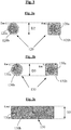
- the minimum thickness (denoted Em) of the thermoplastic sheath (120b, 130b) covering the steel monofilaments (120a, 130a) of the second (120) and / or third (130) (more preferably second and third) composite reinforcements, as shown schematically in Figures 3a, 3b and 3c , is preferably between 5 and 150 ⁇ m, more preferably between 10 and 100 ⁇ m, in particular between 15 and 50 ⁇ m.
- thermoplastic sheath having a rigidity intermediate between the rigidity of the steel monofilaments and the rigidity of the rubber matrix coating them, the stresses exerted at the interfaces are reduced, which is likely to further improve the overall endurance of the multilayer laminate of the tire of the invention.
- the thermoplastic material is a polymer or a polymer composition (that is to say a composition based on at least one polymer and at least one additive).
- This thermoplastic polymer is preferably chosen from the group consisting of polyamides, polyesters, polyimides and mixtures of such polymers; more particularly, this polymer is a polyamide or a polyester.
- polyamides aliphatic
- polyesters mention may be made more particularly of PET (polyethylene terephthalate), PEN (polyethylene naphthalate), PBT (polybutylene terephthalate), PBN (polybutylene naphthalate), PPT (polypropylene terephthalate), PPN (polypropylene naphthalate).
- thermoplastic material preferably themselves thermoplastics, capable of promoting adhesion to a diene rubber matrix, for example TPS elastomers (styrenic thermoplastics) of the unsaturated type, in particular epoxidized, as described for example in the applications WO 2013/117474 and WO 2013/117475 .
- TPS elastomers styrenic thermoplastics
- the sheath comprises a single layer of thermoplastic material.
- the sheath could however include several separate layers, at least one of them, or even all, being thermoplastic material.
- the second (120) and third (130) reinforcements according to the invention have a diameter (or by definition a thickness if their cross section is not circular), respectively denoted D2 and D3, which is between 0.20 mm and 0.50 mm.
- D2 and D3 can be the same or different from one layer to another; if they are different, D3 can be greater than D2 or even less than D2, according to the particular embodiments of the invention.
- D2 and / or D3 are greater than 0.25 mm and less than 0.40 mm. More preferably, for optimal endurance of the tire of the invention, in particular under severe driving conditions, it is preferred that D2 and / or D3 (more preferably D2 and D3) are included in a range of 0.28 to 0.35 mm.
- the steel is carbon steel, such as for example those used in “steel cords " type cables for tires; but it is of course possible to use other steels, for example stainless steels, or other alloys.
- a carbon steel when a carbon steel is used, its carbon content (% by weight of steel) is within a range of 0.5% to 1.2%, more preferably 0.7 % to 1.0%.
- the invention applies in particular to steels of the steel cord type with normal resistance (called “NT” for “Normal Tensile ”) or with high resistance (said “HT” for “High Tensile “), the (second and third ) carbon steel reinforcements then having a tensile strength (Rm) which is preferably greater than 2000 MPa, more preferably greater than 2500 MPa.
- the invention also applies to steels of the steel cord type with very high resistance (called “SHT” for " Super High Tensile "), ultra-high resistance (called “UHT” for “Ultra High Tensile “ or “MT” for “Mega Tensile “), the (second and third) carbon steel reinforcements then having a tensile strength (Rm) which is preferably greater than 3000 MPa, more preferably greater than 3500 MPa.
- Rm tensile strength
- the total elongation at break (At) of these reinforcements, the sum of the elastic elongation and the plastic elongation, is preferably greater than 2.0%.
- the steel used may itself be coated, before sheathing with the thermoplastic material, with a metal layer improving for example the properties of implementation of the steel monofilament, or the use properties of the reinforcement and / or the tire themselves, such as the properties of adhesion, of resistance to corrosion or of resistance to aging.
- the steel can for example be covered with a layer of brass (Zn-Cu alloy) or zinc; it is recalled in particular that during the wire manufacturing process, the coating of brass or zinc facilitates the wire drawing, as well as the bonding of the wire with the rubber.
- the step of sheathing or covering the steel monowires with the thermoplastic material is carried out in a manner well known to those skilled in the art, for example by passing the monowire, or even if necessary several monowires arranged in parallel, through one or more dies of suitable diameter, in extrusion heads heated to appropriate temperatures, or in a coating bath containing the thermoplastic material previously dissolved in an appropriate organic solvent (or mixture of solvents).
- the monofilament (s) thus sheathed are then cooled sufficiently so as to solidify the layer of thermoplastic material, for example with air or another cold gas, or by passage through a bath of water followed by a drying step.
- the steel monowires can be subjected to an adhesion treatment in order to improve the subsequent adhesion between the steel and the thermoplastic sheath.
- the sheath of thermoplastic material is then provided with an adhesive layer with respect to each layer of rubber composition with which it is in contact.
- any suitable adhesive system may be used, for example a simple textile adhesive of the "RFL" type (resorcinol-formaldehyde-latex) comprising at least one diene elastomer such as natural rubber, or any equivalent glue known to impart satisfactory adhesion between rubber and conventional thermoplastic fibers such as polyester or polyamide fibers, such as, for example, the adhesive compositions described in the applications WO 2013/017421 , WO 2013/017422 , WO 2013/017423 .
- the sizing process can essentially comprise the following successive steps: passage through a glue bath, followed by spinning (for example by blowing, sizing) to remove the excess glue; then drying, for example by passing through a heating oven or tunnel (for example for 30 s at 180 ° C) and finally heat treatment (for example for 30 s at 230 ° C).
- thermoplastic material for example mechanically and / or physically and / or chemically, to improve its setting of adhesive and / or its final adhesion to rubber.
- Mechanical treatment could consist, for example, of a prior step of matting or scratching the surface; physical treatment could consist, for example, of treatment with radiation such as an electron beam; a chemical treatment could for example consist of a prior passage through a bath of epoxy resin and / or of isocyanate compound.
- thermoplastic material being generally smooth, it may also be advantageous to add a thickener to the glue used, in order to improve the total setting of glue of the multi-composite reinforcement during its gluing.
- the steel monofilaments sheathed by the thermoplastic sheath represent the majority (by definition, majority in number), more preferably all, of the second (120) reinforcements of the second layer (10b) rubber (C2).
- the steel monofilaments sheathed by the thermoplastic sheath represent the majority, more preferably all, of the third reinforcements (130) of the third layer (10c) of rubber (C3) .
- Each layer (C1, C2, C3) of rubber composition (or hereinafter “rubber layer”) constituting the multilayer composite laminate is based on at least one elastomer and a filler.
- the rubber is a diene rubber, that is to say as a reminder any elastomer (single elastomer or mixture of elastomers) which is derived, at least in part (ie, a homopolymer or a copolymer), from monomers dienes, that is to say monomers carrying two carbon-carbon double bonds, whether the latter are conjugated or not.
- elastomer single elastomer or mixture of elastomers
- monomers dienes that is to say monomers carrying two carbon-carbon double bonds, whether the latter are conjugated or not.
- This diene elastomer is more preferably chosen from the group consisting of polybutadienes (BR), natural rubber (NR), synthetic polyisoprenes (IR), butadiene copolymers, isoprene copolymers, and mixtures of these elastomers , such copolymers being chosen in particular from the group consisting of butadiene-styrene copolymers (SBR), isoprene-butadiene copolymers (BIR), isoprene-styrene copolymers (SIR) and isoprene copolymers- butadiene-styrene (SBIR).
- SBR butadiene-styrene copolymers
- BIR isoprene-butadiene copolymers
- SIR isoprene-styrene copolymers
- SBIR isoprene copolymers- butadiene-styrene
- a particularly preferred embodiment consists in using an “isoprene” elastomer, that is to say a homopolymer or a copolymer of isoprene, in other words a diene elastomer chosen from the group consisting of natural rubber (NR ), synthetic polyisoprenes (IR), the various isoprene copolymers and mixtures of these elastomers.
- isoprene elastomer
- NR natural rubber
- IR synthetic polyisoprenes
- the isoprene elastomer is preferably natural rubber or a synthetic polyisoprene of the cis-1,4 type.
- polyisoprenes are preferably used having a rate (mol%) of cis-1,4 bonds greater than 90%, more preferably still greater than 98%.
- each rubber composition layer comprises 50 to 100 pce of natural rubber.
- the diene elastomer may consist, in whole or in part, of another diene elastomer such as, for example, an SBR elastomer used in combination or not with another elastomer, for example type BR.
- Each rubber composition can comprise one or more diene elastomer (s), also all or part of the additives usually used in rubber matrices intended for the manufacture of tires, such as, for example, reinforcing fillers such as carbon or silica, coupling agents, anti-aging agents, antioxidants, plasticizing agents or extension oils, whether the latter are of aromatic or non-aromatic nature (in particular very weak or non-aromatic oils, for example of the naphthenic or paraffinic type, with high or preferably low viscosity, MES or TDAE oils), plasticizing resins with high glass transition temperature (above 30 ° C.), agents facilitating the implementation (processability ) compositions in the raw state, tackifying resins, anti-reversion agents, acceptors and donors of methylene such as for example HMT (hexamethylenetetrami ne) or H3M (hexamethoxymethylmelamine), reinforcing resins (such as resorcinol or bismaleimide), known
- the crosslinking system of the rubber composition is a so-called vulcanization system, that is to say based on sulfur (or a sulfur donor agent) and a primary vulcanization accelerator.
- a vulcanization system that is to say based on sulfur (or a sulfur donor agent) and a primary vulcanization accelerator.
- various secondary accelerators or known vulcanization activators Sulfur is used at a preferential rate of between 0.5 and 10 phr
- the primary vulcanization accelerator for example a sulfenamide
- the level of reinforcing filler is preferably greater than 30 phr, in particular between 30 and 100 phr.
- carbon blacks all carbon blacks are suitable, in particular blacks of the HAF, ISAF, SAF type conventionally used in tires (so-called pneumatic grade blacks). Among the latter, mention will be made more particularly of carbon blacks of grade (ASTM) 300, 600 or 700 (for example N326, N330, N347, N375, N683, N772).
- Suitable silicas include precipitated or pyrogenic silicas having a BET surface area of less than 450 m 2 / g, preferably from 30 to 400 m 2 / g.
- each rubber composition has, in the crosslinked state, a secant module in extension, at 10% elongation, which is between 4 and 25 MPa, more preferably between 4 and 20 MPa; values in particular between 5 and 15 MPa have been found to be particularly suitable.
- the modulus measurements are carried out in tension, unless otherwise indicated according to standard ASTM D 412 of 1998 (test piece “C"): the secant module is measured in second elongation (that is to say after an accommodation cycle) "true” (that is to say reduced to the real section of the test piece) at 10% elongation, noted here Ms and expressed in MPa (normal conditions of temperature and hygrometry according to standard ASTM D 1349 from 1999).
- any suitable adhesive system may be used, for example a textile adhesive of the "RFL” type (resorcinol-formaldehyde- latex) or equivalent for the first textile reinforcements and the steel monofilaments sheathed by their thermoplastic material.
- RLL resorcinol-formaldehyde- latex
- the sheath 120b, 130b
- the sheath can be circular, square or else rectangular ( Fig. 3a, 3b and 3c ). It could also be for example of oblong shape.
- the steel monofilaments sheathed with the thermoplastic material can be sheathed individually as indicated by way of example in Figures 3a and 3b , this constituting a preferred embodiment. However, according to another preferred embodiment, it is several steel monofilaments (all or part of the reinforcements 120 and / or 130 of the laminate) which could be collectively sheathed by the same thermoplastic sheath, as indicated by way of example at the figure 3c where the final reinforcement 130 here consists of 4 monofilaments in steel (130a) which have been sheathed collectively by a single sheath of thermoplastic material (130b).
- thermoplastic material for example polyester or polyamide
- the material sheathing the steel monofilaments can be particularly advantageous since no compatibility problem then arises between the respective reinforcements, in particular in the event of parasitic direct contact between the latter.
- Ez 1 is the average of the thicknesses (Ez 1 (1) , Ez 1 (2) , Ez 1 (3) , ..., Ez 1 (i) ) of rubber separating a first reinforcement (110) from the second reinforcement ( 120) which is closest to it, these thicknesses each being measured in the radial direction Z, and averaged over a total axial distance between - 5.0 cm and + 5.0 cm from the center of the belt (i.e., for example in total about 100 measurements if there are ten reinforcements (110) per cm in the layer C1).
- Ez 1 is the average of the minimum distances Ez 1 (i) separating "back to back" each first reinforcement (110) from the second reinforcement (120), of course with the sheath included, which is closest to it in the radial direction Z, this average being calculated over all of the first reinforcements (110) present in the central part of the belt, in an axial interval extending between - 5 cm and + 5 cm relative to the median plane M.
- Ez 2 is the average of the thicknesses of rubber (Ez 2 (1) , Ez 2 (2) , Ez 2 (3) , ..., Ez 2 (i) ) separating a second reinforcement (120) from the third reinforcement (130) which is closest to it, measured in the radial direction Z, this average being calculated over a total axial distance between - 5.0 cm and + 5.0 cm from the center of the belt.
- these thicknesses represent the minimum distances which separate “back to back” the second reinforcement (120) from the third reinforcement (130) which is closest to it in the radial direction Z.
- Ez 2 is the average of the minimum distances Ez 2 (i) separating "back to back" each second reinforcement (120) from the third reinforcement (130), of course with the sheaths included, which is closest to it in the radial direction Z, this average being calculated over all of the second reinforcements (120) present in the central part of the belt, in an axial interval extending between - 5 cm and + 5 cm relative to the median plane M.
- the tire of the invention preferably checks at least one of the following inequalities (more preferably all three): 0.15 ⁇ Ez 1 / Ez 1 + D 1 + D 2 ⁇ 0.30 0.20 ⁇ Ez 2 / Ez 2 + D 2 + D 3 ⁇ 0.50 0.20 ⁇ Ez 1 + Ez 2 / Ez 1 + Ez 2 + D 1 + D 2 + D 3 ⁇ 0.40 .
- the invention offers the possibility of maintaining at a low level or even further reducing the thickness of the tire belts and that of the rubber layers constituting a part of their structure, ultimately the weight and the rolling resistance of the tires. tires, without risk of direct contact between the various reinforcements.
- the multi-layer composite laminate is better protected from humidity thanks to the use in its first layer of multifilament textile fibers individually twisted on themselves.
- thermoplastic sheath also constitutes an effective barrier against corrosive agents capable of penetrating into the multilayer laminate in the event of attacks by the tire.
- this sheath having a rigidity intermediate between those of the steel monofilaments and of the rubber matrix coating them, the stresses exerted at the interfaces are reduced, which is likely to improve the overall endurance of the multilayer composite laminate of the tire of the tire. 'invention.
Landscapes
- Engineering & Computer Science (AREA)
- Mechanical Engineering (AREA)
- Textile Engineering (AREA)
- Tires In General (AREA)
- Ropes Or Cables (AREA)
Applications Claiming Priority (2)
| Application Number | Priority Date | Filing Date | Title |
|---|---|---|---|
| FR1550813A FR3032148B1 (fr) | 2015-02-03 | 2015-02-03 | Pneu radial ayant une structure de ceinture amelioree |
| PCT/EP2016/051304 WO2016124418A1 (fr) | 2015-02-03 | 2016-01-22 | Pneu radial ayant une structure de ceinture améliorée |
Publications (2)
| Publication Number | Publication Date |
|---|---|
| EP3253596A1 EP3253596A1 (fr) | 2017-12-13 |
| EP3253596B1 true EP3253596B1 (fr) | 2020-06-03 |
Family
ID=53008680
Family Applications (1)
| Application Number | Title | Priority Date | Filing Date |
|---|---|---|---|
| EP16701180.8A Active EP3253596B1 (fr) | 2015-02-03 | 2016-01-22 | Pneu radial ayant une structure de ceinture améliorée |
Country Status (6)
| Country | Link |
|---|---|
| US (1) | US20180022158A1 (es) |
| EP (1) | EP3253596B1 (es) |
| JP (1) | JP6896634B2 (es) |
| KR (2) | KR20170115510A (es) |
| FR (1) | FR3032148B1 (es) |
| WO (1) | WO2016124418A1 (es) |
Families Citing this family (4)
| Publication number | Priority date | Publication date | Assignee | Title |
|---|---|---|---|---|
| FR3032149B1 (fr) | 2015-02-03 | 2017-02-17 | Michelin & Cie | Pneu radial ayant une structure de ceinture tres fine |
| FR3048638B1 (fr) | 2016-03-11 | 2018-03-30 | Compagnie Generale Des Etablissements Michelin | Pneu radial ayant une structure de ceinture amelioree |
| CN112004691B (zh) * | 2018-04-17 | 2022-05-24 | 米其林集团总公司 | 用于重型土木工程车辆的充气轮胎的包括不同层的保护增强件 |
| KR102288493B1 (ko) * | 2020-03-19 | 2021-08-10 | 넥센타이어 주식회사 | 타이어용 스틸코드 및 타이어용 스틸코드의 제조방법 |
Family Cites Families (9)
| Publication number | Priority date | Publication date | Assignee | Title |
|---|---|---|---|---|
| DE2853006C2 (de) * | 1978-12-07 | 1993-12-16 | Uniroyal Englebert Gmbh | Fahrzeugluftreifen |
| JP4053727B2 (ja) * | 2000-11-22 | 2008-02-27 | 住友ゴム工業株式会社 | 空気入りラジアルタイヤ |
| US20120241068A1 (en) * | 2009-11-26 | 2012-09-27 | Bridgestone Corporation | Pneumatic tire |
| US20110259501A1 (en) * | 2010-04-26 | 2011-10-27 | Mahmoud Cherif Assaad | Hybrid cord in a belt ply for a pneumatic tire |
| FR2971188B1 (fr) * | 2011-02-03 | 2013-03-08 | Michelin Soc Tech | Renfort composite gaine d'une couche de polymere auto-adherente au caoutchouc |
| WO2013099248A1 (ja) * | 2011-12-26 | 2013-07-04 | 横浜ゴム株式会社 | 空気入りラジアルタイヤ |
| FR2986740B1 (fr) * | 2012-02-09 | 2014-03-21 | Michelin & Cie | Pneumatique a structure de ceinture allegee |
| FR2986739B1 (fr) * | 2012-02-09 | 2014-03-21 | Michelin & Cie | Pneumatique a structure de ceinture allegee |
| FR3008998B1 (fr) * | 2013-07-29 | 2016-01-01 | Michelin & Cie | Produit renforce a faible epaisseur et pneumatique comprenant ce produit |
-
2015
- 2015-02-03 FR FR1550813A patent/FR3032148B1/fr not_active Expired - Fee Related
-
2016
- 2016-01-22 EP EP16701180.8A patent/EP3253596B1/fr active Active
- 2016-01-22 JP JP2017541096A patent/JP6896634B2/ja active Active
- 2016-01-22 KR KR1020177021234A patent/KR20170115510A/ko active Application Filing
- 2016-01-22 KR KR1020237043676A patent/KR20240000640A/ko active Search and Examination
- 2016-01-22 WO PCT/EP2016/051304 patent/WO2016124418A1/fr active Application Filing
- 2016-01-22 US US15/547,979 patent/US20180022158A1/en not_active Abandoned
Non-Patent Citations (1)
| Title |
|---|
| None * |
Also Published As
| Publication number | Publication date |
|---|---|
| KR20170115510A (ko) | 2017-10-17 |
| FR3032148B1 (fr) | 2017-02-17 |
| FR3032148A1 (fr) | 2016-08-05 |
| EP3253596A1 (fr) | 2017-12-13 |
| US20180022158A1 (en) | 2018-01-25 |
| JP6896634B2 (ja) | 2021-06-30 |
| KR20240000640A (ko) | 2024-01-02 |
| WO2016124418A1 (fr) | 2016-08-11 |
| JP2018504317A (ja) | 2018-02-15 |
Similar Documents
| Publication | Publication Date | Title |
|---|---|---|
| EP3253592B1 (fr) | Pneu radial ayant une structure de ceinture très fine | |
| EP3253597B1 (fr) | Pneu radial ayant une structure de ceinture améliorée | |
| EP2812195B1 (fr) | Pneumatique a structure de ceinture allegee | |
| EP3253598B1 (fr) | Pneu radial ayant une structure de ceinture ameliorée | |
| EP2812194B1 (fr) | Pneumatique a structure de ceinture allégée | |
| EP3027429B1 (fr) | Pneu radial à structure de ceinture allégée | |
| EP3027424B1 (fr) | Pneu radial à structure de ceinture allégée | |
| EP3448695B1 (fr) | Pneu avion ayant une armature de carcasse à endurance améliorée | |
| EP3426503B1 (fr) | Pneu radial avec structure de ceinture améliorée | |
| EP3253596B1 (fr) | Pneu radial ayant une structure de ceinture améliorée | |
| EP3253593B1 (fr) | Pneu radial ayant une structure de ceinture améliorée renforcée de monofilaments | |
| EP3253594B1 (fr) | Pneu radial ayant une structure de ceinture ameliorée | |
| EP3253595B1 (fr) | Pneu radial ayant une structure de ceinture améliorée | |
| WO2024017580A1 (fr) | Tissu pour pneumatique comprenant des éléments de renfort comprenant un assemblage constitué de deux brins multifilamentaires de polyamide 5,6 |
Legal Events
| Date | Code | Title | Description |
|---|---|---|---|
| STAA | Information on the status of an ep patent application or granted ep patent |
Free format text: STATUS: THE INTERNATIONAL PUBLICATION HAS BEEN MADE |
|
| PUAI | Public reference made under article 153(3) epc to a published international application that has entered the european phase |
Free format text: ORIGINAL CODE: 0009012 |
|
| STAA | Information on the status of an ep patent application or granted ep patent |
Free format text: STATUS: REQUEST FOR EXAMINATION WAS MADE |
|
| 17P | Request for examination filed |
Effective date: 20170904 |
|
| AK | Designated contracting states |
Kind code of ref document: A1 Designated state(s): AL AT BE BG CH CY CZ DE DK EE ES FI FR GB GR HR HU IE IS IT LI LT LU LV MC MK MT NL NO PL PT RO RS SE SI SK SM TR |
|
| AX | Request for extension of the european patent |
Extension state: BA ME |
|
| DAV | Request for validation of the european patent (deleted) | ||
| DAX | Request for extension of the european patent (deleted) | ||
| RAP1 | Party data changed (applicant data changed or rights of an application transferred) |
Owner name: COMPAGNIE GENERALE DES ETABLISSEMENTS MICHELIN |
|
| RIC1 | Information provided on ipc code assigned before grant |
Ipc: B60C 9/00 20060101ALI20191001BHEP Ipc: B60C 9/22 20060101ALI20191001BHEP Ipc: B60C 9/18 20060101AFI20191001BHEP Ipc: B60C 9/20 20060101ALI20191001BHEP |
|
| GRAP | Despatch of communication of intention to grant a patent |
Free format text: ORIGINAL CODE: EPIDOSNIGR1 |
|
| STAA | Information on the status of an ep patent application or granted ep patent |
Free format text: STATUS: GRANT OF PATENT IS INTENDED |
|
| INTG | Intention to grant announced |
Effective date: 20200107 |
|
| GRAS | Grant fee paid |
Free format text: ORIGINAL CODE: EPIDOSNIGR3 |
|
| GRAA | (expected) grant |
Free format text: ORIGINAL CODE: 0009210 |
|
| STAA | Information on the status of an ep patent application or granted ep patent |
Free format text: STATUS: THE PATENT HAS BEEN GRANTED |
|
| AK | Designated contracting states |
Kind code of ref document: B1 Designated state(s): AL AT BE BG CH CY CZ DE DK EE ES FI FR GB GR HR HU IE IS IT LI LT LU LV MC MK MT NL NO PL PT RO RS SE SI SK SM TR |
|
| REG | Reference to a national code |
Ref country code: GB Ref legal event code: FG4D Free format text: NOT ENGLISH |
|
| REG | Reference to a national code |
Ref country code: AT Ref legal event code: REF Ref document number: 1276648 Country of ref document: AT Kind code of ref document: T Effective date: 20200615 Ref country code: CH Ref legal event code: EP |
|
| REG | Reference to a national code |
Ref country code: DE Ref legal event code: R096 Ref document number: 602016037418 Country of ref document: DE |
|
| REG | Reference to a national code |
Ref country code: LT Ref legal event code: MG4D |
|
| PG25 | Lapsed in a contracting state [announced via postgrant information from national office to epo] |
Ref country code: SE Free format text: LAPSE BECAUSE OF FAILURE TO SUBMIT A TRANSLATION OF THE DESCRIPTION OR TO PAY THE FEE WITHIN THE PRESCRIBED TIME-LIMIT Effective date: 20200603 Ref country code: GR Free format text: LAPSE BECAUSE OF FAILURE TO SUBMIT A TRANSLATION OF THE DESCRIPTION OR TO PAY THE FEE WITHIN THE PRESCRIBED TIME-LIMIT Effective date: 20200904 Ref country code: NO Free format text: LAPSE BECAUSE OF FAILURE TO SUBMIT A TRANSLATION OF THE DESCRIPTION OR TO PAY THE FEE WITHIN THE PRESCRIBED TIME-LIMIT Effective date: 20200903 Ref country code: LT Free format text: LAPSE BECAUSE OF FAILURE TO SUBMIT A TRANSLATION OF THE DESCRIPTION OR TO PAY THE FEE WITHIN THE PRESCRIBED TIME-LIMIT Effective date: 20200603 Ref country code: FI Free format text: LAPSE BECAUSE OF FAILURE TO SUBMIT A TRANSLATION OF THE DESCRIPTION OR TO PAY THE FEE WITHIN THE PRESCRIBED TIME-LIMIT Effective date: 20200603 |
|
| REG | Reference to a national code |
Ref country code: NL Ref legal event code: MP Effective date: 20200603 |
|
| PG25 | Lapsed in a contracting state [announced via postgrant information from national office to epo] |
Ref country code: LV Free format text: LAPSE BECAUSE OF FAILURE TO SUBMIT A TRANSLATION OF THE DESCRIPTION OR TO PAY THE FEE WITHIN THE PRESCRIBED TIME-LIMIT Effective date: 20200603 Ref country code: HR Free format text: LAPSE BECAUSE OF FAILURE TO SUBMIT A TRANSLATION OF THE DESCRIPTION OR TO PAY THE FEE WITHIN THE PRESCRIBED TIME-LIMIT Effective date: 20200603 Ref country code: RS Free format text: LAPSE BECAUSE OF FAILURE TO SUBMIT A TRANSLATION OF THE DESCRIPTION OR TO PAY THE FEE WITHIN THE PRESCRIBED TIME-LIMIT Effective date: 20200603 Ref country code: BG Free format text: LAPSE BECAUSE OF FAILURE TO SUBMIT A TRANSLATION OF THE DESCRIPTION OR TO PAY THE FEE WITHIN THE PRESCRIBED TIME-LIMIT Effective date: 20200903 |
|
| REG | Reference to a national code |
Ref country code: AT Ref legal event code: MK05 Ref document number: 1276648 Country of ref document: AT Kind code of ref document: T Effective date: 20200603 |
|
| PG25 | Lapsed in a contracting state [announced via postgrant information from national office to epo] |
Ref country code: NL Free format text: LAPSE BECAUSE OF FAILURE TO SUBMIT A TRANSLATION OF THE DESCRIPTION OR TO PAY THE FEE WITHIN THE PRESCRIBED TIME-LIMIT Effective date: 20200603 Ref country code: AL Free format text: LAPSE BECAUSE OF FAILURE TO SUBMIT A TRANSLATION OF THE DESCRIPTION OR TO PAY THE FEE WITHIN THE PRESCRIBED TIME-LIMIT Effective date: 20200603 |
|
| PG25 | Lapsed in a contracting state [announced via postgrant information from national office to epo] |
Ref country code: ES Free format text: LAPSE BECAUSE OF FAILURE TO SUBMIT A TRANSLATION OF THE DESCRIPTION OR TO PAY THE FEE WITHIN THE PRESCRIBED TIME-LIMIT Effective date: 20200603 Ref country code: RO Free format text: LAPSE BECAUSE OF FAILURE TO SUBMIT A TRANSLATION OF THE DESCRIPTION OR TO PAY THE FEE WITHIN THE PRESCRIBED TIME-LIMIT Effective date: 20200603 Ref country code: CZ Free format text: LAPSE BECAUSE OF FAILURE TO SUBMIT A TRANSLATION OF THE DESCRIPTION OR TO PAY THE FEE WITHIN THE PRESCRIBED TIME-LIMIT Effective date: 20200603 Ref country code: SM Free format text: LAPSE BECAUSE OF FAILURE TO SUBMIT A TRANSLATION OF THE DESCRIPTION OR TO PAY THE FEE WITHIN THE PRESCRIBED TIME-LIMIT Effective date: 20200603 Ref country code: IT Free format text: LAPSE BECAUSE OF FAILURE TO SUBMIT A TRANSLATION OF THE DESCRIPTION OR TO PAY THE FEE WITHIN THE PRESCRIBED TIME-LIMIT Effective date: 20200603 Ref country code: AT Free format text: LAPSE BECAUSE OF FAILURE TO SUBMIT A TRANSLATION OF THE DESCRIPTION OR TO PAY THE FEE WITHIN THE PRESCRIBED TIME-LIMIT Effective date: 20200603 Ref country code: PT Free format text: LAPSE BECAUSE OF FAILURE TO SUBMIT A TRANSLATION OF THE DESCRIPTION OR TO PAY THE FEE WITHIN THE PRESCRIBED TIME-LIMIT Effective date: 20201006 Ref country code: EE Free format text: LAPSE BECAUSE OF FAILURE TO SUBMIT A TRANSLATION OF THE DESCRIPTION OR TO PAY THE FEE WITHIN THE PRESCRIBED TIME-LIMIT Effective date: 20200603 |
|
| PG25 | Lapsed in a contracting state [announced via postgrant information from national office to epo] |
Ref country code: IS Free format text: LAPSE BECAUSE OF FAILURE TO SUBMIT A TRANSLATION OF THE DESCRIPTION OR TO PAY THE FEE WITHIN THE PRESCRIBED TIME-LIMIT Effective date: 20201003 Ref country code: SK Free format text: LAPSE BECAUSE OF FAILURE TO SUBMIT A TRANSLATION OF THE DESCRIPTION OR TO PAY THE FEE WITHIN THE PRESCRIBED TIME-LIMIT Effective date: 20200603 Ref country code: PL Free format text: LAPSE BECAUSE OF FAILURE TO SUBMIT A TRANSLATION OF THE DESCRIPTION OR TO PAY THE FEE WITHIN THE PRESCRIBED TIME-LIMIT Effective date: 20200603 |
|
| REG | Reference to a national code |
Ref country code: DE Ref legal event code: R097 Ref document number: 602016037418 Country of ref document: DE |
|
| PLBE | No opposition filed within time limit |
Free format text: ORIGINAL CODE: 0009261 |
|
| STAA | Information on the status of an ep patent application or granted ep patent |
Free format text: STATUS: NO OPPOSITION FILED WITHIN TIME LIMIT |
|
| PG25 | Lapsed in a contracting state [announced via postgrant information from national office to epo] |
Ref country code: DK Free format text: LAPSE BECAUSE OF FAILURE TO SUBMIT A TRANSLATION OF THE DESCRIPTION OR TO PAY THE FEE WITHIN THE PRESCRIBED TIME-LIMIT Effective date: 20200603 |
|
| 26N | No opposition filed |
Effective date: 20210304 |
|
| PG25 | Lapsed in a contracting state [announced via postgrant information from national office to epo] |
Ref country code: SI Free format text: LAPSE BECAUSE OF FAILURE TO SUBMIT A TRANSLATION OF THE DESCRIPTION OR TO PAY THE FEE WITHIN THE PRESCRIBED TIME-LIMIT Effective date: 20200603 |
|
| PG25 | Lapsed in a contracting state [announced via postgrant information from national office to epo] |
Ref country code: MC Free format text: LAPSE BECAUSE OF FAILURE TO SUBMIT A TRANSLATION OF THE DESCRIPTION OR TO PAY THE FEE WITHIN THE PRESCRIBED TIME-LIMIT Effective date: 20200603 |
|
| REG | Reference to a national code |
Ref country code: CH Ref legal event code: PL |
|
| GBPC | Gb: european patent ceased through non-payment of renewal fee |
Effective date: 20210122 |
|
| PG25 | Lapsed in a contracting state [announced via postgrant information from national office to epo] |
Ref country code: LU Free format text: LAPSE BECAUSE OF NON-PAYMENT OF DUE FEES Effective date: 20210122 |
|
| REG | Reference to a national code |
Ref country code: BE Ref legal event code: MM Effective date: 20210131 |
|
| PG25 | Lapsed in a contracting state [announced via postgrant information from national office to epo] |
Ref country code: GB Free format text: LAPSE BECAUSE OF NON-PAYMENT OF DUE FEES Effective date: 20210122 Ref country code: LI Free format text: LAPSE BECAUSE OF NON-PAYMENT OF DUE FEES Effective date: 20210131 Ref country code: CH Free format text: LAPSE BECAUSE OF NON-PAYMENT OF DUE FEES Effective date: 20210131 |
|
| PG25 | Lapsed in a contracting state [announced via postgrant information from national office to epo] |
Ref country code: IE Free format text: LAPSE BECAUSE OF NON-PAYMENT OF DUE FEES Effective date: 20210122 |
|
| PG25 | Lapsed in a contracting state [announced via postgrant information from national office to epo] |
Ref country code: IS Free format text: LAPSE BECAUSE OF FAILURE TO SUBMIT A TRANSLATION OF THE DESCRIPTION OR TO PAY THE FEE WITHIN THE PRESCRIBED TIME-LIMIT Effective date: 20201003 |
|
| PG25 | Lapsed in a contracting state [announced via postgrant information from national office to epo] |
Ref country code: BE Free format text: LAPSE BECAUSE OF NON-PAYMENT OF DUE FEES Effective date: 20210131 |
|
| PG25 | Lapsed in a contracting state [announced via postgrant information from national office to epo] |
Ref country code: CY Free format text: LAPSE BECAUSE OF FAILURE TO SUBMIT A TRANSLATION OF THE DESCRIPTION OR TO PAY THE FEE WITHIN THE PRESCRIBED TIME-LIMIT Effective date: 20200603 |
|
| PG25 | Lapsed in a contracting state [announced via postgrant information from national office to epo] |
Ref country code: HU Free format text: LAPSE BECAUSE OF FAILURE TO SUBMIT A TRANSLATION OF THE DESCRIPTION OR TO PAY THE FEE WITHIN THE PRESCRIBED TIME-LIMIT; INVALID AB INITIO Effective date: 20160122 |
|
| PG25 | Lapsed in a contracting state [announced via postgrant information from national office to epo] |
Ref country code: MK Free format text: LAPSE BECAUSE OF FAILURE TO SUBMIT A TRANSLATION OF THE DESCRIPTION OR TO PAY THE FEE WITHIN THE PRESCRIBED TIME-LIMIT Effective date: 20200603 |
|
| PGFP | Annual fee paid to national office [announced via postgrant information from national office to epo] |
Ref country code: DE Payment date: 20240119 Year of fee payment: 9 |
|
| PGFP | Annual fee paid to national office [announced via postgrant information from national office to epo] |
Ref country code: FR Payment date: 20240124 Year of fee payment: 9 |
|
| PG25 | Lapsed in a contracting state [announced via postgrant information from national office to epo] |
Ref country code: MT Free format text: LAPSE BECAUSE OF FAILURE TO SUBMIT A TRANSLATION OF THE DESCRIPTION OR TO PAY THE FEE WITHIN THE PRESCRIBED TIME-LIMIT Effective date: 20200603 |