EP3252898A1 - Verbinder und verfahren zum abdichten eines verbinders - Google Patents
Verbinder und verfahren zum abdichten eines verbinders Download PDFInfo
- Publication number
- EP3252898A1 EP3252898A1 EP17000803.1A EP17000803A EP3252898A1 EP 3252898 A1 EP3252898 A1 EP 3252898A1 EP 17000803 A EP17000803 A EP 17000803A EP 3252898 A1 EP3252898 A1 EP 3252898A1
- Authority
- EP
- European Patent Office
- Prior art keywords
- cable
- connector
- sealing element
- pressure elements
- sealing
- Prior art date
- Legal status (The legal status is an assumption and is not a legal conclusion. Google has not performed a legal analysis and makes no representation as to the accuracy of the status listed.)
- Granted
Links
Images



Classifications
-
- H—ELECTRICITY
- H02—GENERATION; CONVERSION OR DISTRIBUTION OF ELECTRIC POWER
- H02G—INSTALLATION OF ELECTRIC CABLES OR LINES, OR OF COMBINED OPTICAL AND ELECTRIC CABLES OR LINES
- H02G15/00—Cable fittings
- H02G15/02—Cable terminations
- H02G15/04—Cable-end sealings
Definitions
- the invention relates to a connector, in particular a push-pull connector, and a method for sealing a connector.
- Previous connectors in particular push-pull connectors, have a limited protective effect against externally penetrating liquids and / or penetrating dust.
- known connectors and / or push-pull connectors do not meet the protection standards IP67, IP68, and IP69K.
- a sealing element e.g. a piece of rubber and / or a rubber hose or the like, disposed between a cable arranged in the connector and a housing part of the connector.
- the sealing element is squeezed by the housing part relative to the cable, wherein in each case between the sealing element and the cable and / or the housing part sealing surfaces are formed.
- the sealing surfaces thus formed have only a small contact surface, so that a reliable sealing of the connector against liquids and / or dust is not guaranteed.
- channeling may occur between the sealing member and the cable and / or the sealing member and the housing member. Through such channels, a liquid and / or dust can penetrate into the connector.
- the cable feedthrough may have a substantially hollow cylindrical shape. That is, the grommet has an inner diameter and an outer diameter, wherein the difference between outer diameter and inner diameter defines the wall and / or the wall thickness of the cable gland. Furthermore, the cable feedthrough may have a first opening and a second opening, which are designed in such a way that a cable and / or cable end can be introduced into the cable feedthrough along the cylinder axis of the cable feedthrough or can be executed. In this case, the first opening of the second opening may be arranged opposite, so that the substantially hollow cylindrical wall extends from the first opening in the direction of the second opening.
- the inner diameter of the grommet can be made larger than the outer diameter of the received cable and / or cable end to allow a recording of the cable and / or the cable end in the cable gland.
- the cable end may be inserted along a cable guide direction in the cable gland.
- the connecting portion of the connector may be configured to be connected to a complementary receptacle.
- the cable routing direction is the direction that extends from a cable-side end of the connector to a plug-side end of the connector.
- the cable guiding direction extends from a first portion of the connector which is formed to the cable and / or cable end introduce, towards a second region which is formed connectable with a complementary female connector.
- the cylinder axis of the cable feedthrough may be formed substantially parallel to the cable guide direction.
- the cable feedthrough may extend from the first opening along the cable guide direction towards the second opening.
- the inner diameter and / or outer diameter of the grommet may vary along the cable routing direction.
- the at least partially disposed between the cable end and the cable gland first sealing element may have a substantially hollow cylindrical and / or rotationally cylindrical shape and be elongated in cable management direction.
- the cylinder and / or the axis of rotation of the first Dichturigselements may be formed substantially parallel to the cable guide direction.
- the first sealing element may be configured to have an inner diameter suitable for receiving the cable and / or cable end.
- the inner diameter of the first seal member may be formed at least partially larger than the outer diameter of the received cable and / or cable end.
- the sealing element has an outer diameter which is suitable for locating the sealing element in the cable feedthrough, wherein the outer diameter of the sealing element along the cable guiding direction can be made variable.
- the outer diameter of the seal member may change along the cable guide direction.
- the movable pressure elements may be elongate and extend from the cable feedthrough against the cable guide direction. In other words, the movable pressure elements may extend from a cable-side end of the cable feedthrough opposite to the cable guide direction.
- the movable pressure elements can be arranged opposite one another with respect to the cylinder axis of the cable feedthrough. In other words, the movable pressure elements can be arranged radially around the accommodated cable and / or cable end.
- the first sealing element may be disposed at least partially between the plurality of movable pressure elements and the received cable and / or cable end.
- the cross section of the opening defined by the movable pressure elements is smaller than in an unattached state of the cable and / or the cable end.
- the movable pressure elements in the fastening position can press the first sealing element against the recorded cable and / or cable end.
- the longitudinally along the cable guide direction formed first sealing member thus seals the gap between the inside of the cable gland and the recorded cable and / or cable end.
- the first sealing element forms a large sealing surface both on its inside and on its outside.
- the movable pressure element can be formed as an extension of the cable bushing elastically deformable.
- the grommet and the movable pressure elements may be integrally formed.
- the cable feedthrough and / or the movable pressure elements may be made of plastic and / or of a CuZn alloy, in particular a CuZn 39 Pb 3 alloy. Due to the lead content, such an alloy is very well suited for exciting machining.
- the connector may include a securing element for moving the movable printing elements to the mounting position.
- the securing element can be designed to be connectable to the connector such that the movable pressure elements automatically in the attachment position are moved when the fuse element is connected to the connector.
- the fuse element may be formed on an arrangement portion provided on the cable-side end of the connector.
- the securing element may be screwed to the connector.
- the securing element is moved along the cable guide direction towards the plug-side end of the connector.
- the movable pressure elements are moved toward the cable and / or cable end.
- the securing element can have a narrowing inner surface, that is to say an inner diameter which increases in the direction of the cable guide and which is in contact with the outer circumference of the movable pressure elements.
- inside also means “radially inside” and “outside” also “radially outside”, the term “radial” referring to a direction which points radially away from the cable guide direction.
- the first sealing element may have a projection, wherein the projection engages in a complementary recess of the movable pressure elements.
- the projection of the first sealing element may in particular on the outside, i. the side facing away from the cable and / or cable end, be arranged at the cable end of the first sealing element.
- the projection may be formed to extend radially outwardly from the outside of the first sealing element.
- the complementary recess in the plurality of movable pressure elements on the inside, i. the cable and / or cable end facing side, the movable pressure elements may be arranged.
- the engagement of the projection of the first sealing element in the complementary Recess of the movable printing elements may allow for improved power transmission when the movable printing elements are moved toward the mounting position.
- the sealing element can be pressed flat, ie with the inside of the first sealing element, against the cable and / or cable end.
- the first sealing element can be simultaneously pressed and / or compressed in the cable guiding direction.
- the first sealing element may be formed around a partial region of the cable end between 3 mm and 10 mm long, preferably at least 4.2 mm long.
- the first sealing element can also be made shorter, as long as the corresponding tightness is ensured.
- the elongated design of the sealing element in the cable guiding direction can ensure that a correspondingly large sealing surface is formed between the first sealing element and the cable and / or cable end.
- the cable and / or the cable end can be sealed by the sealing element dust and / or liquid-tight.
- the cable and / or cable end can be arranged within the cable feedthrough such that the cable and / or cable end protrudes relative to the cable feedthrough in the cable guide direction.
- the cable and / or cable end can survive between 0.1 mm and 10 mm, particularly preferably between 0.5 mm and 6 mm.
- the inner diameter of the first sealing element can at least partially shrink in cable guide direction.
- the inner diameter of the first sealing element can be partially reduced in the cable guiding direction. Due to the decreasing inner diameter of the first seal member along the cable guide direction, the cable and / or cable end can be easily included in the connector, as in the cable receiving only a small area the inside of the first sealing element is in contact with the accommodated cable and / or cable end.
- the inside of the first sealing member at the one or more sections with widened inner diameter towards the cable end When taking the mounting position can be pressed by the movements of the movable pressure elements towards the cable end, the inside of the first sealing member at the one or more sections with widened inner diameter towards the cable end.
- the first seal member along the cable guide direction has a substantially constant inner diameter, wherein the inner diameter substantially corresponds to the outer diameter of the received cable and / or cable end. That the inside of the first sealing element is substantially (fully) flat against the outside of the received cable and / or cable end.
- the cable gland of the connector may have a constriction, wherein the first sealing element is arranged at the constriction.
- the narrowing of the cable feedthrough can be formed on the inside of the cable feedthrough in the cable guiding direction.
- the constriction may be formed as an abrupt and / or stepped reduction of the inner diameter of the cable feedthrough in the cable guide direction.
- a plug-side end of the first sealing element may be arranged on the constriction, wherein the outer diameter of the first sealing element is greater than the inner diameter of the constriction.
- an end face of the first sealing element which is formed at the plug-side end of the first sealing element, abut flat against the constriction.
- a first sealing surface is disposed at the throat, which is orthogonal to the cable guiding direction and extends radially outwardly.
- the second sealing surface is arranged between the cable feedthrough and the first sealing element parallel to the cable guiding direction.
- the plurality of pressure elements may be formed claw-shaped and or "L" -shaped, wherein the claw-shaped pressure elements extending from the cable entry opposite to the cable guide direction.
- a recess may be provided between two adjacent pressure elements, which space the adjacent pressure elements from each other.
- the pressure elements can be arranged radially around the recorded cable and / or cable end.
- the first sealing element can be received and / or held or arranged in the (claw-shaped) pressure elements.
- the connector may include a housing, wherein the cable gland is disposed within the housing. Furthermore, the connector may include a second sealing member disposed between the grommet and the housing.
- the housing may be formed substantially hollow cylindrical and have an inner diameter which is adapted to receive the cable gland.
- the hollow cylindrical shape of the housing may extend along the cable guiding direction, wherein the housing has a cable-side end and a plug-side end.
- the second sealing member may be configured to seal the connector against liquids and / or dust.
- the connector may have on the outside of the cable feedthrough a circumferential recess in which the second sealing element is arranged.
- the recess may in particular be formed radially on the outside of the cable feedthrough.
- the securing element can be designed to be connectable to the housing and / or screwed.
- the securing element can be designed to be connectable to the housing such that the plurality of printing elements is moved into the fastening position.
- the securing element may be formed on an arrangement area provided on the cable-side end of the housing.
- the securing element When connecting and / or screwing the fuse element at the cable end of the housing, the securing element is moved along the cable guiding direction towards a plug-side end of the housing and / or the plug-side end of the connector.
- the plurality of movable pressure elements By moving the securing element in the cable guiding direction towards the plug-side end of the connector and / or housing, the plurality of movable pressure elements are moved towards the cable and / or cable end, whereby the sealing described above is achieved.
- the second sealing element may be formed as a sealing ring.
- FIG. 1 shows a perspective view of a mounted connector 100, which is designed as a push-pull connector.
- a cable-side end KE of the connector 100 is configured to receive a cable end of a cable 200.
- the connector 100 extends from its cable-side end KE along a cable guide direction K toward a plug-side end SE of the connector 100.
- At the plug-side end SE of the connector 100 may be provided a complementary socket, wherein the connector 100 may be formed connectable to the complementary socket ,
- the cable routing direction K substantially corresponds to the direction in which the cable end of the cable 200 is inserted and / or arranged in the connector 100 or the current direction through the connector 100 Figures 1-4b
- the cable routing direction thus corresponds essentially to the Z-direction of the superimposed coordinate system.
- FIG. 1 a connectable to the connector 100 formed fuse element 30, which at the cable end of the connector KE 100th is arranged.
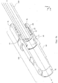
- FIGS. 2a and 2 B each show a longitudinal section through a cable bushing 10, which within the in FIG. 1 shown connector 100 is arranged.
- the cable bushing 10 is substantially hollow-cylindrical, wherein the cylinder axis H is formed substantially parallel to the cable guide K direction.
- the cable gland 10 extends from a cable-side end KEK of the cable gland 10 along the cable gearing direction K to a plug-side end SEK of the cable gland 10, wherein the cable end of the cable 200 can be inserted at the cable end end KEK of the cable gland 10 into same.
- the cable feedthrough 10 has both a variable inner diameter and a variable outer diameter along the cable guide direction.
- a plurality of movable pressure elements 11 extend from a cable-side end KEK of the cable feedthrough 10 counter to the cable-guiding direction.
- the plurality of movable pressure elements 11 may comprise at least two, preferably six or even more movable pressure elements 11.
- the movable pressure elements 11 are arranged radially around the cylinder axis H and are designed to be movable in the direction of the cylinder axis H. Furthermore, the pressure elements 11 can also be moved outwardly, i. be formed radially movable away from the cylinder axis H.
- the pressure elements 11 are elongated and claw-shaped or substantially L-shaped and extend counter to the cable guide direction. Furthermore, adjacent pressure elements 11 are each spaced from each other by a recess or spacing 12. By moving the pressure elements 11 toward the cylinder axis H and / or towards a cable 200 and / or cable end arranged in the cable bushing 10, the recesses or spacings 12 are at least partially reduced.
- the recesses or spacings 12 are formed obliquely relative to the cylinder axis H, so that the recesses or spacings 12 are formed substantially helically around the cylinder axis H around.
- the movable pressure elements 11 have an im Essentially thread-shaped course around the cylinder axis H around.
- the movable pressure elements 11 and the cable bushing 10 are integrally formed from the same material, in particular as a press, - pressure and / or casting component.
- FIGS. 2a and 2 B show a recess 13 which is formed in the pressure elements 11.
- the recess 13 is formed substantially annularly at the cable end of the cable duct 10 and extends on an inner side of the movable pressure elements 11, that is, on a side which faces the cylinder axis H. Furthermore, the recess 13 penetrates the pressure elements 11 partially in the radial direction to the outside, ie away from the cylinder axis H.
- the cable bushing 10 has a constriction 14 in its course from the cable-side end KE along the cable guide direction to the plug-side end SE. At the constriction 14, the inner diameter of the cable duct 10 decreases abruptly.
- FIGS. 2a and 2 B a circumferential recess or guide groove 15, which is on the outside of the cable gland 10, that is arranged on the cylinder axis H side facing away from the cable gland 10.
- the circumferential recess or guide groove 15 extends on the outside of the cable gland 10 fully circumferentially.
- FIGS. 3a and 3b show a longitudinal section through the cable gland 10 along the cable guide direction K and the cylinder axis H, wherein within the cable gland 10, a first sealing element 20 is arranged.
- the first sealing element 20 has a substantially hollow cylindrical shape and / or rotationally symmetrical shape, wherein the cylinder axis H of the first sealing element 20 coincides with the cylinder axis H of the cable feedthrough 10.
- the cable guiding direction K is substantially parallel to the cylinder axis H of the first sealing member 20.
- a circumferential projection 21 is formed on the cable side end KED of the first seal member 20. It is envisaged that the projection 21 is arranged in the recess 13 of the cable gland. The projection 21 has a stepwise radially outward into the recess 13 in.
- a plug-side end SED of the first seal member 20 is disposed on the restriction 14.
- the outer diameter of the first sealing element 20 is formed adjacent to the constriction 14 larger than the inner diameter of the cable duct 10 at the constriction 14.
- an end face 22 of the first pressure element 20 bears against the constriction 14 at the plug-side end SED of the first sealing element 20.
- the first sealing member 20 extends from the recess 13 along the cable guide direction to the constriction 14, wherein the outside of the first seal member 20 is disposed substantially on the inside of the cable gland 10 and / or thus rests against the inside of the cable gland 10.
- FIGS. 3a and 3b Further show FIGS. 3a and 3b in that the inner diameter of the first sealing element 20 decreases in sections in the cable guiding direction.
- the inside of the first sealing element 20 is pressed against a cable 200 received in the cable bushing 10 and / or cable end, so that the inside of the first sealing element 20 is substantially parallel to the cylinder axis H of the first sealing element 20. Furthermore, the sealing element 20 is pressed and / or compressed in the cable guiding direction, so that the end face seals with the constriction 14. Furthermore, the outside of the first sealing element 20 seals towards the inside of the cable feedthrough 10.
- FIGS. 4a and 4b each show a longitudinal section through a partially assembled connector 100 along the cable guide direction. Inside the connector 100 is a cable end of the cable 200 is received and / or arranged. In the state shown, the first sealing element 20 is at least partially disposed between the received cable end of the cable 200 and the cable gland 10.
- the housing element 50 has a substantially hollow cylindrical shape and extends along the cable guide direction K.
- a cylinder axis H of the housing element 50 essentially coincides with the cylinder axis H of the cable feedthrough 10.
- the cable bushing 10 is arranged within the housing element 50, wherein the housing element 50 is formed along the cylinder axis H longer than the cable bushing 10 along the cylinder axis H.
- FIGS. 4a and 4b in each case the securing element 30, which is connectable to the cable-side end KE of the connector 100.
- the securing element 30 is connectable to a cable-side end KE of the housing element 50.
- the securing element 30 may be screwed to the housing element 50.
- the fuse element 30 is connected to the housing element 50, the fuse element is moved along the cable guide direction to a plug-side end SE of the housing element 50.
- the securing element 30 is designed such that it can move the plurality of movable pressure elements 11 arranged in the securing element 30 in the direction of the cable 200.
- the inside of the first sealing element 20 is moved and / or pressed towards the cable 200, the inside of the first sealing element 20 and the region of the cable 200 covered by the first sealing element 20 being sealed against externally penetrating liquids and / or dust.
- FIGS. 4a and 4b a second sealing member 40 which is disposed between the housing member 50 and the cable duct 10.
- the second sealing element 40 is arranged circumferentially on the outside of the cable bushing 10 and can, for example, as a sealing ring be educated.
- the second sealing element 40 is disposed in the circumferential recess 15 of the cable gland 10.
- the housing element 50 squeezes and / or presses the second sealing element 40 into the recess 15, so that the second sealing element 40 is arranged in the recess 15 in a form-fitting manner.
- the housing element 50 is sealed against the cable bushing liquid and / or dustproof.
Landscapes
- Connector Housings Or Holding Contact Members (AREA)
Abstract
Description
- Die Erfindung betrifft einen Verbinder, insbesondere einen Push-Pull-Verbinder, sowie ein Verfahren zum Abdichten eines Verbinders.
- Bisherige Verbinder, insbesondere Push-Pull-Verbinder, weisen eine begrenzte Schutzwirkung gegen von außen eindringende Flüssigkeiten und/oder eindringenden Staub auf. Insbesondere erfüllen bekannte Verbinder und/oder Push-Pull-Verbinder nicht die Schutznormen IP67, IP68, und IP69K.
- In bekannten Verbindern ist ein Dichtungselement, z.B. ein Stück Gummi und/oder ein Gummischlauch oder Ähnliches, zwischen einem im Verbinder angeordnetem Kabel und einem Gehäuseteil des Verbinders angeordnet. Das Dichtungselement wird durch das Gehäuseteil gegenüber dem Kabel gequetscht, wobei jeweils zwischen dem Dichtungselement und dem Kabel und/oder dem Gehäuseteil Dichtflächen ausgebildet sind. Die derart ausgebildeten Dichtflächen weisen allerdings nur eine geringe Kontaktfläche auf, so dass eine zuverlässige Abdichtung des Verbinders gegenüber Flüssigkeiten und/oder Staub nicht gewährleistet ist. So kann es beim Bewegen des Kabels relativ zum Verbinder zur Bildung von Kanälen zwischen dem Dichtungselement und dem Kabel und/oder dem Dichtungselement und dem Gehäuseteil kommen. Durch derartige Kanäle kann eine Flüssigkeit und/oder Staub in den Verbinder eindringen.
- Es ist daher eine Aufgabe der Erfindung einen Verbinder bereitzustellen, welcher gegen eindringenden Staub und/oder eindringende Flüssigkeiten geschützt ist.
- Diese Aufgabe wird durch die Gegenstände der unabhängigen Ansprüche gelöst. Bevorzugte Ausführungsformen sind in den abhängigen Ansprüchen definiert.
- Ein Aspekt der Erfindung betrifft einen Verbinder, insbesondere einen Push-Pull-Verbinder, umfassend:
- eine Kabeldurchführung zum Aufnehmen eines Kabelendes; und
- ein erstes Dichtungselement, welches zumindest teilweise zwischen dem Kabelende und der Kabeldurchführung angeordnet ist,
- Die Kabeldurchführung kann eine im Wesentlichen hohlzylindrische Form aufweisen. Das heißt, die Kabeldurchführung weist einen Innendurchmesser und einen Außendurchmesser auf, wobei die Differenz zwischen Außendurchmesser und Innendurchmesser die Wandung und/oder die Wandstärke der Kabeldurchführung definiert. Des Weiteren kann die Kabeldurchführung eine erste Öffnung und eine zweite Öffnung aufweisen, welche derart ausgebildet sind, dass ein Kabel und/oder Kabelende in die Kabeldurchführung entlang der Zylinderachse der Kabeldurchführung einführbar bzw. ausführbar bzw. durchführbar ist. Dabei kann die erste Öffnung der zweiten Öffnung gegenüberliegend angeordnet sein, so dass die im Wesentlichen hohlzylindrische Wandung sich von der ersten Öffnung in Richtung zweite Öffnung erstreckt.
- Der Innendurchmesser der Kabeldurchführung kann größer ausgebildet sein als der Außendurchmesser des aufgenommenen Kabels und/oder Kabelendes, um eine Aufnahme des Kabels und/oder des Kabelendes in die Kabeldurchführung zu ermöglichen. Das Kabelende kann entlang einer Kabelführungsrichtung in die Kabeldurchführung eingeführt sein. Als Kabelführungsrichtung kann die Richtung angesehen werden, in welche sich der Verbinder ausgehend von der Kabeldurchführung in Richtung eines Verbindungsbereichs des Verbinders erstreckt. Der Verbindungsbereich des Verbinders kann dazu ausgebildet sein, mit einer komplementären Steckerbuchse verbunden zu werden. Mit anderen Worten ist die Kabelführungsrichtung die Richtung, welche sich von einem kabelseitigen Ende des Verbinders hin zu einem steckerseitigen Ende des Verbinders erstreckt. Anders ausgedrückt, die Kabelführungsrichtung erstreckt sich von einem ersten Bereich des Verbinders, welcher dazu ausgebildet ist, das Kabel und/oder Kabelende einzuführen, hin zu einem zweiten Bereich, der mit einer komplementären Steckerbuchse verbindbar ausgebildet ist. Die Zylinderachse der Kabeldurchführung kann im Wesentlichen parallel zur Kabelführungsrichtung ausgebildet sein. Mit anderen Worten, die Kabeldurchführung kann sich ausgehend von der ersten Öffnung entlang der Kabelführungsrichtung hin zur zweiten Öffnung erstrecken. Darüber hinaus kann der Innendurchmesser und/oder Außendurchmesser der Kabeldurchführung entlang der Kabelführungsrichtung variieren.
- Das zumindest teilweise zwischen dem Kabelende und der Kabeldurchführung angeordnete erste Dichtungselement kann eine im Wesentlichen hohlzylindrische und/oder rotationszylindrische Form aufweisen und in Kabelführungsrichtung länglich ausgebildet sein. Mit anderen Worten, die Zylinder- und/oder die Rotationsachse des ersten Dichturigselements kann im Wesentlichen parallel zur Kabelführungsrichtung ausgebildet sein. Das erste Dichtungselement kann dazu ausgebildet sein, einen Innendurchmesser aufzuweisen, der dazu geeignet ist, das Kabel und/oder Kabelende aufzunehmen. Mit anderen Worten, der Innendurchmesser des ersten Dichtungselements kann zumindest teilweise größer als der Außendurchmesser des aufgenommenen Kabels und/oder Kabelendes ausgebildet sein.
- Des Weiteren weist das Dichtungselement einen Außendurchmesser auf, der dazu geeignet ist, das Dichtungselement in der Kabeldurchführung zu verorten, wobei der Außendurchmesser des Dichtungselements entlang der Kabelführungsrichtung variabel ausgebildet sein kann. Mit anderen Worten, der Außendurchmesser des Dichtungselements kann sich entlang der Kabelführungsrichtung verändern.
- Die bewegbaren Druckelemente können länglich ausgebildet sein und sich ausgehend von der Kabeldurchführung entgegen der Kabelführungsrichtung erstrecken. Mit anderen Worten, die bewegbaren Druckelemente können sich von einem kabelseitigen Ende der Kabeldurchführung entgegen der Kabelführungsrichtung erstrecken. Die bewegbaren Druckelemente können sich bezüglich der Zylinderachse der Kabeldurchführung gegenüberliegend angeordnet sein. Mit anderen Worten, die bewegbaren Druckelemente können um das aufgenommene Kabel und/oder Kabelende radial angeordnet sein.
- Das erste Dichtungselement kann zumindest teilweise zwischen der Mehrzahl von bewegbaren Druckelementen und dem aufgenommenen Kabel und/oder Kabelende angeordnet sein. Durch Bewegen der bewegbaren Druckelemente relativ zum Kabel und/oder Kabelende, kann der Abstand zwischen den bewegbaren Druckelementen und dem Kabel und/oder Kabelende verkleinert bzw. vergrößert werden. Mit anderen Worten, durch Bewegen der bewegbaren Druckelemente relativ zum Kabel und/oder Kabelende, kann sich eine Öffnung, welche um die bewegbaren Druckelemente orthogonal zur Kabelführungsrichtung angeordnet ist, verkleinern oder vergrößern. Insbesondere in der Befestigungsposition, also in einem Zustand in dem das Kabel und/oder Kabelende in dem Verbinder befestigt ist, ist der Querschnitt der durch die bewegbaren Druckelemente definierten Öffnung kleiner als in einem unbefestigten Zustand des Kabels und/oder des Kabelendes. Dadurch können die bewegbaren Druckelemente in der Befestigungsposition das erste Dichtungselement gegen das aufgenommenen Kabel- und/oder Kabelende drücken. Das entlang der Kabelführungsrichtung länglich ausgebildete erste Dichtungselement dichtet somit den Zwischenraum zwischen der Innenseite der Kabeldurchführung und dem aufgenommenen Kabel und/oder Kabelende ab. Das erste Dichtungselement bildet sowohl an seiner Innenseite als auch an seiner Außenseite eine große Dichtfläche. Durch diese in der Befestigungsposition ausgebildete Dichtfläche kann ein Eindringen von Flüssigkeiten und/oder Staub in den Verbinder von außerhalb verhindert werden.
- Insbesondere können die bewegbaren Druckelement als Fortsatz an der Kabeldurchführung elastisch verformbar ausgebildet sein. Mit anderen Worten, die Kabeldurchführung und die bewegbaren Druckelemente können einstückig ausgebildet sein. Des Weiteren können die Kabeldurchführung und/oder die bewegbaren Druckelemente aus Kunststoff und/oder aus einer CuZn Legierung, insbesondere einer CuZn39Pb3 Legierung gefertigt sein. Aufgrund des Bleigehaltes ist eine solche Legierung sehr gut für eine spannende Bearbeitung geeignet.
- Vorzugsweise kann der Verbinder ein Sicherungselement zum Bewegen der bewegbaren Druckelemente in die Befestigungsposition umfassen. Insbesondere kann das Sicherungselement derart verbindbar mit dem Verbinder ausgebildet sein, dass die bewegbaren Druckelemente automatisch in die Befestigungsposition bewegt werden, wenn das Sicherungselement mit dem Verbinder verbunden wird.
- Das Sicherungselement kann an einem Anordnungsbereich, welcher an dem kabelseitigen Ende des Verbinders vorgesehenen ist, ausgebildet sein. Insbesondere, kann das Sicherungselement verschraubbar mit dem Verbinder ausgebildet sein. Beim Verschrauben des Sicherungselements am kabelseitigen Ende des Verbinders wird das Sicherungselement entlang der Kabelführungsrichtung hin zum steckerseitigen Ende des Verbinders bewegt. Durch das Bewegen des Sicherungselements in Kabelführungsrichtung hin zum steckerseitigen Ende des Verbinders werden die bewegbaren Druckelemente zum Kabel und/oder Kabelende hin bewegt. Dazu kann das Sicherungselement eine sich verengende innere Fläche, also einen sich in Kabelführungsrichtung vergrößernden Innendurchmesser aufweisen, die in Kontakt mit dem äußeren Umfang der bewegbaren Druckelemente steht.
- Im Rahmen der Erfindung bedeutet "innen" auch "radial innen" und "außen" auch "radial außen", wobei sich der Begriff "radial" auf eine Richtung bezieht, die radial von der Kabelführungsrichtung weg weist.
- Vorzugsweise kann das erste Dichtungselement einen Vorsprung aufweisen, wobei der Vorsprung in eine komplementäre Aussparung der bewegbaren Druckelemente eingreift.
- Der Vorsprung des ersten Dichtungselements kann insbesondere an der Außenseite, d.h. der dem Kabel und/oder Kabelende abgewandten Seite, am kabelseitigen Ende des ersten Dichtungselements angeordnet sein. Insbesondere kann der Vorsprung von der Außenseite des ersten Dichtungselements radial nach außen verlaufend ausgebildet sein.
- Dahingegen kann die komplementäre Aussparung in der Mehrzahl von bewegbaren Druckelementen auf der Innenseite, d.h. der dem Kabel und/oder Kabelende zugewandten Seite, der bewegbaren Druckelemente angeordnet sein.
- Das Eingreifen des Vorsprungs des ersten Dichtungselements in die komplementäre Aussparung der bewegbaren Druckelemente kann eine verbesserte Kraftübertragung ermöglichen, wenn die bewegbaren Druckelemente in Richtung Befestigungsposition bewegt werden. Insbesondere kann das Dichtungselement flächig, d.h. mit der Innenseite des ersten Dichtungselements, an das Kabel und/oder Kabelende gedrückt werden. Des Weiteren kann das erste Dichtungselement zugleich in Kabelführungsrichtung gedrückt und/oder gestaucht werden.
- Vorzugsweise kann das erste Dichtungselement in der Kabelführungsrichtung, in der das Kabelende durch die Kabeldurchführung geführt ist, um einen Teilbereich des Kabelendes herum zwischen 3 mm und 10 mm lang, bevorzugt zumindest 4,2 mm lang ausgebildet sein. Jedoch kann das erste Dichtungselement auch kürzer ausgebildet sein, so lange die entsprechende Dichtheit gewährleistet ist.
- Durch die längliche Ausbildung des Dichtungselements in Kabelführungsrichtung kann gewährleistet werden, dass eine entsprechend große Dichtfläche zwischen dem ersten Dichtungselement und dem Kabel und/oder Kabelende ausgebildet wird. Somit kann in einer Befestigungsposition das Kabel und/oder das Kabelende durch das Dichtungselement staub- und/oder flüssigkeitsdicht abgedichtet werden.
- Des Weiteren kann das Kabel und/oder Kabelende innerhalb der Kabeldurchführung derart angeordnet sein, dass das Kabel und/oder Kabelende relativ zur Kabeldurchführung in Kabelführungsrichtung übersteht. Insbesondere kann das Kabel und/oder Kabelende zwischen 0,1 mm und 10 mm besonders bevorzugt zwischen 0,5 mm und 6 mm überstehen.
- Vorzugsweise kann sich der Innendurchmesser des ersten Dichtungselements zumindest abschnittsweise in Kabelführungsrichtung verkleinern. Insbesondere wenn die Mehrzahl von Druckelementen nicht in die Befestigungsposition bewegt wurde, kann der Innendurchmesser des ersten Dichtungselements sich abschnittsweise in Kabelführungsrichtung verkleinern. Durch den sich verkleinernden Innendurchmesser des ersten Dichtungselements entlang der Kabelführungsrichtung, kann das Kabel und/oder Kabelende einfach in den Verbinder aufgenommen werden, da bei der Kabelaufnahme nur eine kleine Fläche der Innenseite des ersten Dichtungselements mit dem aufgenommenen Kabel und/oder Kabelende in Kontakt steht.
- Beim Einnehmen der Befestigungsposition kann durch die Bewegungen der bewegbaren Druckelemente hin zum Kabelende die Innenseite des ersten Dichtungselements an dem oder den Abschnitten mit verbreitertem Innendurchmesser hin zum Kabelende gedrückt werden. Somit weist in der Befestigungsposition das erste Dichtungselement entlang der Kabelführungsrichtung einen im Wesentlichen gleichbleibenden Innendurchmesser auf, wobei der Innendurchmesser im Wesentlichen dem Außendurchmesser des aufgenommenen Kabels und/oder Kabelendes entspricht. D.h. die Innenseite des ersten Dichtungselements liegt im Wesentlichen (voll-)flächig an der Außenseite des aufgenommenen Kabels und/oder Kabelendes an.
- Vorzugsweise kann die Kabeldurchführung des Verbinders eine Verengung aufweisen, wobei das erste Dichtungselement an der Verengung angeordnet ist.
- Die Verengung der Kabeldurchführung kann auf der Innenseite der Kabeldurchführung in Kabelführungsrichtung ausgebildet sein. Die Verengung kann insbesondere als eine abrupte und/oder stufenförmige Verkleinerung des Innendurchmessers der Kabeldurchführung in Kabelführungsrichtung ausgebildet sein. Des Weiteren kann ein steckerseitiges Ende des ersten Dichtungselements an der Verengung angeordnet sein, wobei der Außendurchmesser des ersten Dichtungselements größer ist als der Innendurchmesser der Verengung. Dabei kann eine Stirnfläche des ersten Dichtungselements, welche am steckerseitigen Ende des ersten Dichtungselements ausgebildet ist, flächig an der Verengung anliegen. Beim Bewegen der bewegbaren Druckelemente in die Befestigungsposition kann somit das erste Dichtungselement, insbesondere die Stirnfläche des ersten Dichtungselements, an die Verengung gedrückt werden. Somit werden zwei weitere Dichtflächen ausgebildet. Eine erste Dichtfläche ist an der Verengung angeordnet, welche orthogonal zur Kabelführungsrichtung und radial nach außen verläuft. Die zweite Dichtfläche ist zwischen der Kabeldurchführung und dem ersten Dichtungselement parallel zur Kabelführungsrichtung angeordnet. Beim Einnehmen der Befestigungsposition werden diese Dichtflächen staub- und/oder flüssigkeitsdicht abgedichtet.
- Vorzugsweise kann die Mehrzahl der Druckelemente klauenförmig und oder "L"-förmig ausgebildet sein, wobei sich die klauenförmig ausgebildeten Druckelemente ausgehend von der Kabeldurchführung entgegen der Kabelführungsrichtung erstrecken.
- Insbesondere kann zwischen zwei benachbarten Druckelementen eine Aussparung vorgesehen sein, welche die benachbarten Druckelemente voneinander beabstandet. Dabei können die Druckelemente radial um das aufgenommene Kabel und/oder Kabelende angeordnet sein. Des Weiteren kann das erste Dichtungselement in den (klauenförmigen) Druckelementen aufgenommen und/oder gehalten bzw. angeordnet sein.
- Vorzugsweise kann der Verbinder ein Gehäuse umfassen, wobei die Kabeldurchführung innerhalb des Gehäuses angeordnet ist. Des Weiteren kann der Verbinder ein zweites Dichtungselement umfassen, welches zwischen der Kabeldurchführung und dem Gehäuse angeordnet ist.
- Das Gehäuse kann im Wesentlichen hohlzylindrisch ausgebildet sein und einen Innendurchmesser aufweisen, der dazu geeignet ist, die Kabeldurchführung aufzunehmen. Die hohlzylindrische Form des Gehäuses kann sich entlang der Kabelführungsrichtung erstrecken, wobei das Gehäuse ein kabelseitiges Ende und ein steckerseitiges Ende aufweist.
- Das zweite Dichtungselement kann dazu ausgebildet sein, den Verbinder gegen Flüssigkeiten und/oder Staub abzudichten.
- Dazu kann der Verbinder an der Außenseite der Kabeldurchführung eine umlaufende Aussparung aufweisen, in der das zweite Dichtungselement angeordnet ist. Die Aussparung kann insbesondere radial an der Außenseite der Kabeldurchführung ausgebildet sein. Durch eine derartige Anordnung wird beim Assemblieren des Verbinders, das zweite Dichtungselement durch das Gehäuse in die Aussparung gequetscht. Mit anderen Worten, das zweite Dichtungselement kann sich der Form der Aussparung anpassen. Dazu kann das zweite Dichtungselement aus einem gummiartigen flexiblen Material gefertigt sein. Somit entsteht eine vergrößerte Dichtfläche zwischen dem zweiten Dichtungselement und der Aussparung, wodurch die gewünschte Staub- und/oder Flüssigkeitsdichtigkeit erreicht wird. Alternativ oder zusätzlich kann im Gehäuse eine Aussparung für das zweite Dichtungselement ausgebildet sein.
- Des Weiteren kann das Sicherungselement dazu ausgebildet sein, mit dem Gehäuse verbindbar und/oder verschraubbar zu sein. Insbesondere kann das Sicherungselement derart verbindbar mit dem Gehäuse ausgebildet sein, dass die Mehrzahl von Druckelementen in die Befestigungsposition bewegt wird.
- Das Sicherungselement kann an einem am kabelseitigen Ende des Gehäuses vorgesehenen Anordnungsbereich ausgebildet sein. Beim Verbinden und/oder Verschrauben des Sicherungselements am kabelseitigen Ende des Gehäuses wird das Sicherungselement entlang der Kabelführungsrichtung in Richtung hin zu einem steckerseitigen Ende des Gehäuses und/oder dem steckerseitigen Ende des Verbinders bewegt. Durch das Bewegen des Sicherungselements in Kabelführungsrichtung hin zum steckerseitigen Ende des Verbinders und/oder Gehäuses werden die Mehrzahl von bewegbaren Druckelementen zum Kabel und/oder Kabelende hin bewegt, wodurch die oben beschriebene Abdichtung erreicht wird.
- Vorzugsweise kann das zweite Dichtungselement als Dichtungsring ausgebildet sein.
- Ein weiterer Aspekt der Erfindung betrifft ein Verfahren zum Abdichten eines Verbinders, umfassend:
- Aufnehmen eines Kabelendes in einer Kabeldurchführung;
- Anordnen eines ersten Dichtungselements zumindest teilweise zwischen dem Kabelende und der Kabeldurchführung; und
- Bewegen einer Mehrzahl von bewegbaren Druckelementen relativ zum Kabelende derart, dass das erste Dichtungselement von der Mehrzahl von Druckelementen an das Kabelende gedrückt wird.
- Nachfolgend wird eine bevorzugte Ausführungsform des Verbinders anhand der beigefügten Zeichnungen beispielhaft erläutert. Es zeigt:
- Figur 1:
- eine perspektivische Ansicht eines montierten Verbinders mit aufgenommenem Kabel,
- Figur 2a:
- eine perspektivische Ansicht eines Längsschnitts durch eine Kabeldurchführung,
- Figur 2b:
- eine Seitenansicht des Längsschnitts durch die Kabeldurchführung,
- Figur 3a:
- eine perspektivische Ansicht eines Längsschnitts durch die Kabeldurchführung mit einem darin angeordnetem Dichtungselement,
- Figur 3b:
- eine Seitenansicht des Längsschnitts durch die Kabeldurchführung mit dem innenliegenden Dichtungselement,
- Figur 4a:
- eine perspektivische Ansicht eines Längsschnitts durch einen teilmontierten Verbinder, und
- Figur 4b:
- eine Seitenansicht eines Längsschnitts durch den teilmontierten Verbinder.
-
Figur 1 zeigt eine perspektivische Ansicht eines montierten Verbinders 100, der als Push-Pull-Verbinder ausgebildet ist. Ein kabelseitiges Ende KE des Verbinders 100 ist dazu ausgelegt, ein Kabelende eines Kabels 200 aufzunehmen. Der Verbinder 100 erstreckt sich von seinem kabelseitigen Ende KE entlang einer Kabelführungsrichtung K hin zu einem steckerseitigen Ende SE des Verbinders 100. Am steckerseitigen Ende SE des Verbinders 100 kann eine komplementäre Steckerbuchse vorgesehen sein, wobei der Verbinder 100 mit der komplementäre Steckerbuchse verbindbar ausgebildet sein kann. Die Kabelführungsrichtung K entspricht im Wesentlichen der Richtung, in welcher das Kabelende des Kabels 200 in den Verbinder 100 eingeführt ist und/oder angeordnet ist bzw. der Stromrichtung durch den Verbinder 100. In denFiguren 1-4b entspricht die Kabelführungsrichtung somit im Wesentlichen der Z-Richtung des eingeblendeten Koordinatensystems. Des Weiteren zeigtFigur 1 ein mit dem Verbinder 100 verbindbar ausgebildetes Sicherungselement 30, welches am kabelseitigen Ende KE des Verbinders 100 angeordnet ist. -
Figuren 2a und2b zeigen jeweils einen Längsschnitt durch eine Kabeldurchführung 10, welche innerhalb des inFigur 1 gezeigten Verbinders 100 angeordnet ist. Die Kabeldurchführung 10 ist im Wesentlichen hohlzylindrisch ausgebildet, wobei die Zylinderachse H im Wesentlichen parallel zur Kabelführungsrichtung K ausgebildet ist. Die Kabeldurchführung 10 erstreckt sich von einem kabelseitigen Ende KEK der Kabeldurchführung 10 entlang der Kabelführungsrichtung K hin zu einem steckeseitigen Ende SEK der Kabeldurchführung 10, wobei das Kabelende des Kabels 200 am kabelseitigen Ende KEK der Kabeldurchführung 10 in selbige eingeführt werden kann. - Die Kabeldurchführung 10 weist entlang der Kabelführungsrichtung sowohl einen variablen Innendurchmesser als auch einen variablen Außendurchmesser auf. Von einem kabelseitigen Ende KEK der Kabeldurchführung 10 erstreckt sich entgegen der Kabelführungsrichtung eine Mehrzahl von bewegbaren Druckelementen 11. Die Mehrzahl von beweglichen Druckelementen 11 kann mindestens zwei, vorzugsweise sechs oder aber auch mehr bewegbare Druckelemente 11 umfassen. Die bewegbaren Druckelemente 11 sind radial um die Zylinderachse H herum angeordnet und sind in Richtung Zylinderachse H hin beweglich ausgebildet. Des Weiteren können die Druckelemente 11 auch nach außen bewegbar, d.h. sich von der Zylinderachse H radial entfernend bewegbar ausgebildet sein. Wie gezeigt sind die Druckelemente 11 länglich und klauenförmig bzw. im Wesentlichen L-förmig ausgebildet und erstrecken sich entgegen der Kabelführungsrichtung. Des Weiteren sind benachbarte Druckelemente 11 jeweils voneinander durch eine Aussparung bzw. Beabstandung 12 beabstandet. Durch Bewegen der Druckelemente 11 hin zur Zylinderachse H und/oder hin zu einem in der Kabeldurchführung 10 angeordneten Kabels 200 und/oder Kabelendes, werden die Aussparungen bzw. Beabstandungen 12 zumindest teilweise verkleinert.
- Insbesondere sind die Aussparungen bzw. Beabstandungen 12 relativ zur Zylinderachse H schräg ausgebildet, so dass die Aussparungen bzw. Beabstandungen 12 im Wesentlichen gewindeförmig um die Zylinderachse H herum ausgebildet sind. Somit weisen auch die bewegbaren Druckelemente 11 einen im Wesentlichen gewindeförmigen Verlauf um die Zylinderachse H herum auf.
- Vorzugsweise sind die bewegbaren Druckelemente 11 und die Kabeldurchführung 10 einstückig aus dem selben Material, insbesondere als Press,- Druck- und/oder Gießbauteil ausgebildet.
-
Figuren 2a und2b zeigen eine Aussparung 13, welche in den Druckelementen 11 ausgebildet ist. Die Aussparung 13 ist im Wesentlichen ringförmig am kabelseitigen Ende der Kabeldurchführung 10 ausgebildet und verläuft an einer Innenseite der bewegbaren Druckelemente 11, d.h. auf einer Seite, welcher der Zylinderachse H zugewandt ist. Des Weiteren durchdringt die Aussparung 13 die Druckelemente 11 teilweise in radialer Richtung nach Außen, d.h. von der Zylinderachse H weg. - Des Weiteren weist die Kabeldurchführung 10 in ihrem Verlauf vom kabelseitigen Ende KE entlang der Kabelführungsrichtung hin zum steckerseitigen Ende SE eine Verengung 14 auf. An der Verengung 14 verkleinert sich der Innendurchmesser der Kabeldurchführung 10 abrupt.
- Des Weiteren zeigen
Figuren 2a und2b eine umlaufende Aussparung bzw. Führungsrille 15, welche an der Außenseite der Kabeldurchführung 10, d.h. auf der der Zylinderachse H abgewandten Seite der Kabeldurchführung 10, angeordnet ist. Die umlaufende Aussparung bzw. Führungsrille 15 verläuft auf der Außenseite der Kabeldurchführung 10 voll umfänglich. -
Figuren 3a und3b zeigen einen Längsschnitt durch die Kabeldurchführung 10 entlang der Kabelführungsrichtung K bzw. der Zylinderachse H, wobei innerhalb der Kabeldurchführung 10 ein erstes Dichtungselement 20 angeordnet ist. Das erste Dichtungselement 20 weist eine im Wesentlichen hohlzylindrische Form und/oder rotationssymmetrische Form auf, wobei die Zylinderachse H des ersten Dichtungselements 20 mit der Zylinderachse H der Kabeldurchführung 10 zusammen fällt. Somit ist die Kabelführungsrichtung K im Wesentlichen parallel zur Zylinderachse H des ersten Dichtungselements 20. - An der Außenseite des ersten Dichtungselements 20, d.h. an der der Zylinderachse H abgewandten Seite des ersten Dichtungselements 20, ist am kabelseitigen Ende KED des ersten Dichtungselements 20 ein umlaufender Vorsprung 21 ausgebildet. Es ist vorgesehen, dass der Vorsprung 21 in der Aussparung 13 der Kabeldurchführung angeordnet ist. Der Vorsprung 21 weist stufenartig nach radial außen in die Aussparung 13 hinein.
- Ein steckerseitiges Ende SED des ersten Dichtungselements 20 ist an der Verengung 14 angeordnet. Der Außendurchmesser des ersten Dichtungselements 20 ist benachbart zur Verengung 14 größer als der Innendurchmesser der Kabeldurchführung 10 an der Verengung 14 ausgebildet. Somit liegt eine Stirnfläche 22 des ersten Druckelements 20 am steckerseitigen Ende SED des ersten Dichtungselements 20 an der Verengung 14 an.
- Somit erstreckt sich das erste Dichtungselement 20 von der Aussparung 13 entlang der Kabelführungsrichtung bis zur Verengung 14, wobei die Außenseite des ersten Dichtungselements 20 im Wesentlichen an der Innenseite der Kabeldurchführung 10 angeordnet ist und/oder somit an der Innenseite der Kabeldurchführung 10 anliegt.
- Des Weiteren zeigen
Figuren 3a und3b , dass der Innendurchmesser des ersten Dichtungselements 20 sich abschnittsweise in Kabelführungsrichtung verkleinert. - Beim Bewegen der Druckelemente 11 in die Befestigungsposition, d.h. zur Zylinderachse H hin, wird eine Kraft über die Aussparungen 13 und/oder den Vorsprung 21 auf das erste Dichtungselement 20 ausgeübt werden. Dabei wird die Innenseite des ersten Dichtungselements 20 an ein in der Kabeldurchführung 10 aufgenommenes Kabel 200 und/oder Kabelende angepresst, so dass die Innenseite des ersten Dichtungselements 20 im Wesentlichen parallel zur Zylinderachse H des ersten Dichtungselements 20 ist. Des Weiteren wird das Dichtungselement 20 in Kabelführungsrichtung gedrückt und/oder gestaucht, so dass die Stirnfläche dichtend mit der Verengung 14 abschließt. Des Weiteren dichtet die Außenseite des ersten Dichtungselements 20 zur Innenseite der Kabeldurchführung 10 hin ab.
-
Figuren 4a und4b zeigen jeweils einen Längsschnitt durch einen teilmontierten Verbinder 100 entlang der Kabelführungsrichtung. Im Inneren des Verbinders 100 ist ein Kabelende des Kabels 200 aufgenommen und/oder angeordnet. Im gezeigten Zustand ist das erste Dichtungselement 20 zumindest teilweise zwischen dem aufgenommenen Kabelende des Kabels 200 und der Kabeldurchführung 10 angeordnet. - Darüber hinaus zeigen
Figuren 4a und4b jeweils ein Gehäuseelement 50 des Verbinders 100. Das Gehäuseelement 50 weist im eine Wesentlichen hohlzylindrische Form auf und erstreckt sich entlang der Kabelführungsrichtung K. Eine Zylinderachse H des Gehäuseelements 50 fällt im Wesentlichen mit der Zylinderachse H der Kabeldurchführung 10 zusammen. Die Kabeldurchführung 10 ist innerhalb des Gehäuseelements 50 angeordnet, wobei das Gehäuseelement 50 entlang der Zylinderachse H länger ausgebildet ist als die Kabeldurchführung 10 entlang der Zylindeachse H. - Des Weiteren zeigen
Figuren 4a und4b jeweils das Sicherungselement 30, welches mit dem kabelseitigen Ende KE des Verbinders 100 verbindbar ausgebildet ist. Wie gezeigt, ist das Sicherungselement 30 mit einem kabelseitigen Ende KE des Gehäuseelements 50 verbindbar ausgebildet. Zum Beispiel kann das Sicherungselement 30 mit dem Gehäuseelement 50 verschraubbar ausgebildet sein. Beim Verbinden des Sicherungselements 30 mit dem Gehäuseelement 50 wird das Sicherungselement entlang der Kabelführungsrichtung hin zu einem steckerseitigen Ende SE des Gehäuseelements 50 bewegt. Dabei ist das Sicherungselement 30 derartig ausgebildet, dass es die in dem Sicherungselement 30 angeordnete Mehrzahl von bewegbaren Druckelementen 11 in Richtung hin zum Kabel 200 bewegen kann. Entsprechend wird die Innenseite des ersten Dichtungselements 20 zum Kabel 200 hin bewegt und/oder gedrückt, wobei die Innenseite des ersten Dichtungselements 20 und der durch das erste Dichtungselement 20 umfasste Bereich des Kabels 200 gegen von außen eindringende Flüssigkeiten und/oder Staub abgedichtet ist. - Des Weiteren zeigen
Figuren 4a und4b ein zweites Dichtungselement 40, welches zwischen dem Gehäuseelement 50 und der Kabeldurchführung 10 angeordnet ist. Das zweite Dichtungselement 40 ist umlaufend an der Außenseite der Kabeldurchführung 10 angeordnet und kann zum Beispiel als Dichtungsring ausgebildet sein. Wie gezeigt ist das zweite Dichtungselement 40 in der umlaufenden Aussparung 15 der Kabeldurchführung 10 angeordnet. Im montierten Zustand des Verbinders 100 quetscht und/oder drückt das Gehäuseelement 50 das zweite Dichtungselement 40 in die Aussparung 15, so dass das zweite Dichtungselement 40 formschlüssig in der Aussparung 15 angeordnet ist. Dadurch wird das Gehäuseelement 50 gegenüber der Kabeldurchführung flüssigkeits- und/oder staubdicht abgedichtet. -
- 100
- Verbinder
- 200
- Kabel und/oder Kabelende
- 10
- Kabeldurchführung
- 11
- bewegbare Druckelemente
- 12
- Aussparung bzw. Beabstandung
- 13
- komplementäre Aussparung
- 14
- Verengung
- 15
- umlaufende Aussparung/Führungsrille
- 20
- erstes Dichtungselement
- 21
- Vorsprung
- 22
- Stirnfläche steckerseitiges Ende
- 30
- Sicherungselement
- 40
- zweites Dichtungselement
- 50
- Gehäuselement
- KE
- kabelseitiges Ende
- SE
- steckerseitiges Ende
- H
- Zylinderachse
- K
- Kabelfürungsrichtung
- KEK
- kabelseitiges Ende Kabeldurchführung
- SEK
- steckerseitiges Ende Kabeldurchführung
- KED
- kabelseitiges Ende erstes Dichtungselement
- SED
- steckerseitiges Ende zweites Dichtungselement
Claims (12)
- Verbinder (100), insbesondere einen Push-Pull-Verbinder, umfassend:- eine Kabeldurchführung (10) zum Aufnehmen eines Kabelendes (200); und- ein erstes Dichtungselement (20), welches zumindest teilweise zwischen dem Kabelende (200) und der Kabeldurchführung (10) angeordnet ist,wobei an der Kabeldurchführung (10) eine Mehrzahl von relativ zum Kabelende (200) bewegbaren Druckelementen (11) angeordnet ist, die in eine Befestigungsposition bewegbar sind, in der das erste Dichtungselement (20) von der Mehrzahl von Druckelementen (11) an das Kabelende (200) gedrückt ist.
- Verbinder (100) gemäß Anspruch 1, weiter umfassend ein Sicherungselement (30) zum Bewegen der Mehrzahl von Druckelementen (11) in die Befestigungsposition.
- Verbinder (100) gemäß Anspruch 2, wobei das Sicherungselement (30) so mit dem Verbinder (100) verbindbar ist, dass die Mehrzahl von Druckelementen (30) in die Befestigungsposition bewegt wird.
- Verbinder (100) gemäß einem der vorhergehenden Ansprüche, wobei das erste Dichtungselement (20) einen Vorsprung (21) aufweist und der Vorsprung (21) in eine komplementäre Aussparung (13) der Mehrzahl von bewegbaren Druckelementen (11) eingreift.
- Verbinder (100) gemäß einem der vorhergehenden Ansprüche, wobei das erste Dichtungselement (20) in eine Kabelführungsrichtung (K), in der das Kabelende (200) durch die Kabeldurchführung (10) geführt ist, um einen Teilbereich des Kabelendes (200) herum zumindest 5mm lang ausgebildet ist.
- Verbinder (100) gemäß einem der vorhergehenden Ansprüche, wobei der Innendurchmesser des ersten Dichtungselements (20) sich zumindest abschnittsweise in Kabelführungsrichtung (K) verkleinert.
- Verbinder (100) gemäß einem der vorhergehenden Ansprüche, wobei die Kabeldurchführung (10) eine Verengung (14) aufweist und wobei das erste Dichtungselement (20) an der Verengung (14) angeordnet ist.
- Verbinder (100) gemäß einem der vorhergehenden Ansprüche, wobei die Mehrzahl der Druckelemente (11) klauenförmig ausgebildet ist und sich ausgehend von der Kabeldurchführung (10) entgegen der Kabelführungsrichtung (K) erstrecken.
- Verbinder (100) gemäß einem der vorhergehenden Ansprüche, weiter umfassend:- ein Gehäuse (50), wobei die Kabeldurchführung (10) innerhalb des Gehäuses (50) angeordnet ist; und- ein zweites Dichtungselement (40), welches zwischen der Kabeldurchführung (10) und dem Gehäuse (50) angeordnet ist.
- Verbinder (100) gemäß Anspruch 9, wobei die Kabeldurchführung eine umlaufende Aussparung (15) aufweist, und
wobei das zweite Dichtungselement (40) in der umlaufenden Aussparung (15) der Kabeldurchführung (10) angeordnet ist. - Verbinder (100) gemäß Anspruch 9 oder 10, wobei das zweite Dichtungselement (40) als Dichtungsring ausgebildet ist.
- Verfahren zum Abdichten eines Verbinders (100), umfassend:- Aufnehmen eines Kabelendes (200) in einer Kabeldurchführung (10);- Anordnen eines ersten Dichtungselements (20) zumindest teilweise zwischen dem Kabelende (200) und der Kabeldurchführung (10); und- Bewegen einer Mehrzahl von bewegbaren Druckelementen (11) relativ zum Kabelende (200) derart, dass das erste Dichtungselement (10) von der Mehrzahl von Druckelementen an das Kabelende gedrückt wird.
Applications Claiming Priority (1)
| Application Number | Priority Date | Filing Date | Title |
|---|---|---|---|
| DE102016006728.4A DE102016006728A1 (de) | 2016-06-01 | 2016-06-01 | Verbinder und Verfahren zum Abdichten eines Verbinders |
Publications (2)
| Publication Number | Publication Date |
|---|---|
| EP3252898A1 true EP3252898A1 (de) | 2017-12-06 |
| EP3252898B1 EP3252898B1 (de) | 2022-09-21 |
Family
ID=58701362
Family Applications (1)
| Application Number | Title | Priority Date | Filing Date |
|---|---|---|---|
| EP17000803.1A Active EP3252898B1 (de) | 2016-06-01 | 2017-05-09 | Verbinder und verfahren zum abdichten eines verbinders |
Country Status (2)
| Country | Link |
|---|---|
| EP (1) | EP3252898B1 (de) |
| DE (1) | DE102016006728A1 (de) |
Cited By (1)
| Publication number | Priority date | Publication date | Assignee | Title |
|---|---|---|---|---|
| EP3531512A1 (de) * | 2017-12-11 | 2019-08-28 | Yamaichi Electronics Deutschland GmbH | Steckverbinder mit spannzange |
Citations (6)
| Publication number | Priority date | Publication date | Assignee | Title |
|---|---|---|---|---|
| DE2902174A1 (de) * | 1978-01-26 | 1979-08-02 | Kitagawa Ind Co Ltd | Befestigungsvorrichtung |
| EP0218116A2 (de) * | 1985-10-05 | 1987-04-15 | Hermann Kleinhuis GmbH. & Co. KG | Verschraubung aus Kunstoff zur Ein- und Durchführung, Abdichtung und Zugentlastung von Kabeln, Leitungen oder Schläuchen |
| WO2002067399A1 (en) * | 2001-02-20 | 2002-08-29 | Hawke Cable Glands Limited | Cable gland assembly |
| US20030085575A1 (en) * | 2000-07-21 | 2003-05-08 | Joseph Crestin | Device for axially retaining a cylindrical element and more particularly a cable |
| DE10312749A1 (de) * | 2003-03-21 | 2004-10-07 | Pflitsch Gmbh & Co. Kg | Verschraubung für abgedichtete Leitungsdurchführungen |
| DE102011057064A1 (de) * | 2011-12-27 | 2013-06-27 | Phoenix Contact Gmbh & Co. Kg | Kabelverschraubung |
Family Cites Families (5)
| Publication number | Priority date | Publication date | Assignee | Title |
|---|---|---|---|---|
| US4273405A (en) * | 1979-08-13 | 1981-06-16 | Thomas & Betts Corporation | Jacketed metal clad cable connector |
| DE29916204U1 (de) * | 1999-09-15 | 2000-01-05 | Intercontec GmbH, 94336 Hunderdorf | Kontaktierungseinrichtung für den Kabelschirm in elektrischen Steckverbindern |
| DE10011341C2 (de) * | 2000-03-10 | 2002-03-07 | Aloys Mennekes Anlagengmbh & C | Elektrische Steckvorrichtung |
| GB0605606D0 (en) * | 2006-03-21 | 2006-04-26 | Lucas Nicholas A | Cable glands |
| DE102012024072A1 (de) * | 2012-12-07 | 2014-06-12 | Yamaichi Electronics Deutschland Gmbh | Dichtungsvorrichtung, Verbinder und Herstellungsverfahren |
-
2016
- 2016-06-01 DE DE102016006728.4A patent/DE102016006728A1/de active Pending
-
2017
- 2017-05-09 EP EP17000803.1A patent/EP3252898B1/de active Active
Patent Citations (6)
| Publication number | Priority date | Publication date | Assignee | Title |
|---|---|---|---|---|
| DE2902174A1 (de) * | 1978-01-26 | 1979-08-02 | Kitagawa Ind Co Ltd | Befestigungsvorrichtung |
| EP0218116A2 (de) * | 1985-10-05 | 1987-04-15 | Hermann Kleinhuis GmbH. & Co. KG | Verschraubung aus Kunstoff zur Ein- und Durchführung, Abdichtung und Zugentlastung von Kabeln, Leitungen oder Schläuchen |
| US20030085575A1 (en) * | 2000-07-21 | 2003-05-08 | Joseph Crestin | Device for axially retaining a cylindrical element and more particularly a cable |
| WO2002067399A1 (en) * | 2001-02-20 | 2002-08-29 | Hawke Cable Glands Limited | Cable gland assembly |
| DE10312749A1 (de) * | 2003-03-21 | 2004-10-07 | Pflitsch Gmbh & Co. Kg | Verschraubung für abgedichtete Leitungsdurchführungen |
| DE102011057064A1 (de) * | 2011-12-27 | 2013-06-27 | Phoenix Contact Gmbh & Co. Kg | Kabelverschraubung |
Cited By (1)
| Publication number | Priority date | Publication date | Assignee | Title |
|---|---|---|---|---|
| EP3531512A1 (de) * | 2017-12-11 | 2019-08-28 | Yamaichi Electronics Deutschland GmbH | Steckverbinder mit spannzange |
Also Published As
| Publication number | Publication date |
|---|---|
| DE102016006728A1 (de) | 2017-12-07 |
| EP3252898B1 (de) | 2022-09-21 |
Similar Documents
| Publication | Publication Date | Title |
|---|---|---|
| DE69734971T2 (de) | Koaxialkabelverbinder | |
| DE60225672T2 (de) | Kabelverschraubungszusammenbau | |
| EP3682515B1 (de) | Kabelabdichtung mit einem gehäuse sowie anordnung mit der kabelabdichtung | |
| EP1524731B1 (de) | Steckergehäuse mit verbesserter Kabelabdichtung | |
| EP2764591B1 (de) | Kabeldurchführung und verfahren zur montage einer kabeldurchführung | |
| DE3787068T2 (de) | Feuchtigkeitssichere Abdichtung für Koaxialverbinder. | |
| DE2522499C2 (de) | Elektrischer Steckverbinder | |
| DE60122455T2 (de) | Verbinder für ein semirigides Koaxialkabel | |
| DE69735432T2 (de) | Zugentlastung und werkzeug zu deren anbringung | |
| EP3453080B1 (de) | Umspritzter steckverbinder | |
| DE102013109653B4 (de) | Steckverbindergehäuse und Verfahren zum Öffnen seines Kabelabgangs | |
| DE202009009807U1 (de) | Manipulationssichere Kabeldurchführung | |
| DE102019001136A1 (de) | Kabeleinführvorrichtung für ein in einer Leitung aufgenommenes elektrisches Kabel | |
| EP3382818B1 (de) | Dichtvorrichtung, verfahren und verwendung | |
| EP2532061A2 (de) | Elektrisches gerät mit einer durchführung eines kabels durch eine gehäusewand | |
| WO2018138108A1 (de) | Kabeldurchführung mit abschirmenden und abdichtenden eigenschaften | |
| DE102008019165A1 (de) | Kabelverschraubung, insbesondere für ein Abschirm- oder Erdungskabel | |
| DE69716138T2 (de) | Externer erdungsisolations-verbinder für kabelspleissverschlüsse | |
| DE102014112045B4 (de) | Steckverbinder sowie Steckverbindergehäuse mit einem Dichtelement | |
| DE2123053A1 (de) | Gegenüber hochfrequenten Störungen abgeschirmte Steckverbindungen für ein mehradriges Kabel | |
| DE102017128089B4 (de) | Geschirmter Rundsteckverbinder | |
| DE10334518A1 (de) | Kabelabdichtung für einen Steckverbinder | |
| DE102016006300B4 (de) | Stellantrieb mit wasserdichter Kabeldurchführung | |
| DE202007017488U1 (de) | Steckeranordnung | |
| EP3252898B1 (de) | Verbinder und verfahren zum abdichten eines verbinders |
Legal Events
| Date | Code | Title | Description |
|---|---|---|---|
| PUAI | Public reference made under article 153(3) epc to a published international application that has entered the european phase |
Free format text: ORIGINAL CODE: 0009012 |
|
| STAA | Information on the status of an ep patent application or granted ep patent |
Free format text: STATUS: THE APPLICATION HAS BEEN PUBLISHED |
|
| AK | Designated contracting states |
Kind code of ref document: A1 Designated state(s): AL AT BE BG CH CY CZ DE DK EE ES FI FR GB GR HR HU IE IS IT LI LT LU LV MC MK MT NL NO PL PT RO RS SE SI SK SM TR |
|
| AX | Request for extension of the european patent |
Extension state: BA ME |
|
| STAA | Information on the status of an ep patent application or granted ep patent |
Free format text: STATUS: REQUEST FOR EXAMINATION WAS MADE |
|
| 17P | Request for examination filed |
Effective date: 20180529 |
|
| RBV | Designated contracting states (corrected) |
Designated state(s): AL AT BE BG CH CY CZ DE DK EE ES FI FR GB GR HR HU IE IS IT LI LT LU LV MC MK MT NL NO PL PT RO RS SE SI SK SM TR |
|
| STAA | Information on the status of an ep patent application or granted ep patent |
Free format text: STATUS: EXAMINATION IS IN PROGRESS |
|
| 17Q | First examination report despatched |
Effective date: 20181016 |
|
| GRAP | Despatch of communication of intention to grant a patent |
Free format text: ORIGINAL CODE: EPIDOSNIGR1 |
|
| STAA | Information on the status of an ep patent application or granted ep patent |
Free format text: STATUS: GRANT OF PATENT IS INTENDED |
|
| INTG | Intention to grant announced |
Effective date: 20220608 |
|
| GRAS | Grant fee paid |
Free format text: ORIGINAL CODE: EPIDOSNIGR3 |
|
| GRAA | (expected) grant |
Free format text: ORIGINAL CODE: 0009210 |
|
| STAA | Information on the status of an ep patent application or granted ep patent |
Free format text: STATUS: THE PATENT HAS BEEN GRANTED |
|
| AK | Designated contracting states |
Kind code of ref document: B1 Designated state(s): AL AT BE BG CH CY CZ DE DK EE ES FI FR GB GR HR HU IE IS IT LI LT LU LV MC MK MT NL NO PL PT RO RS SE SI SK SM TR |
|
| REG | Reference to a national code |
Ref country code: GB Ref legal event code: FG4D Free format text: NOT ENGLISH |
|
| REG | Reference to a national code |
Ref country code: CH Ref legal event code: EP |
|
| REG | Reference to a national code |
Ref country code: IE Ref legal event code: FG4D Free format text: LANGUAGE OF EP DOCUMENT: GERMAN |
|
| REG | Reference to a national code |
Ref country code: DE Ref legal event code: R096 Ref document number: 502017013821 Country of ref document: DE |
|
| REG | Reference to a national code |
Ref country code: AT Ref legal event code: REF Ref document number: 1520444 Country of ref document: AT Kind code of ref document: T Effective date: 20221015 |
|
| REG | Reference to a national code |
Ref country code: LT Ref legal event code: MG9D |
|
| REG | Reference to a national code |
Ref country code: NL Ref legal event code: MP Effective date: 20220921 |
|
| PG25 | Lapsed in a contracting state [announced via postgrant information from national office to epo] |
Ref country code: SE Free format text: LAPSE BECAUSE OF FAILURE TO SUBMIT A TRANSLATION OF THE DESCRIPTION OR TO PAY THE FEE WITHIN THE PRESCRIBED TIME-LIMIT Effective date: 20220921 Ref country code: RS Free format text: LAPSE BECAUSE OF FAILURE TO SUBMIT A TRANSLATION OF THE DESCRIPTION OR TO PAY THE FEE WITHIN THE PRESCRIBED TIME-LIMIT Effective date: 20220921 Ref country code: NO Free format text: LAPSE BECAUSE OF FAILURE TO SUBMIT A TRANSLATION OF THE DESCRIPTION OR TO PAY THE FEE WITHIN THE PRESCRIBED TIME-LIMIT Effective date: 20221221 Ref country code: LV Free format text: LAPSE BECAUSE OF FAILURE TO SUBMIT A TRANSLATION OF THE DESCRIPTION OR TO PAY THE FEE WITHIN THE PRESCRIBED TIME-LIMIT Effective date: 20220921 Ref country code: LT Free format text: LAPSE BECAUSE OF FAILURE TO SUBMIT A TRANSLATION OF THE DESCRIPTION OR TO PAY THE FEE WITHIN THE PRESCRIBED TIME-LIMIT Effective date: 20220921 Ref country code: FI Free format text: LAPSE BECAUSE OF FAILURE TO SUBMIT A TRANSLATION OF THE DESCRIPTION OR TO PAY THE FEE WITHIN THE PRESCRIBED TIME-LIMIT Effective date: 20220921 |
|
| PG25 | Lapsed in a contracting state [announced via postgrant information from national office to epo] |
Ref country code: HR Free format text: LAPSE BECAUSE OF FAILURE TO SUBMIT A TRANSLATION OF THE DESCRIPTION OR TO PAY THE FEE WITHIN THE PRESCRIBED TIME-LIMIT Effective date: 20220921 Ref country code: GR Free format text: LAPSE BECAUSE OF FAILURE TO SUBMIT A TRANSLATION OF THE DESCRIPTION OR TO PAY THE FEE WITHIN THE PRESCRIBED TIME-LIMIT Effective date: 20221222 |
|
| PG25 | Lapsed in a contracting state [announced via postgrant information from national office to epo] |
Ref country code: SM Free format text: LAPSE BECAUSE OF FAILURE TO SUBMIT A TRANSLATION OF THE DESCRIPTION OR TO PAY THE FEE WITHIN THE PRESCRIBED TIME-LIMIT Effective date: 20220921 Ref country code: RO Free format text: LAPSE BECAUSE OF FAILURE TO SUBMIT A TRANSLATION OF THE DESCRIPTION OR TO PAY THE FEE WITHIN THE PRESCRIBED TIME-LIMIT Effective date: 20220921 Ref country code: PT Free format text: LAPSE BECAUSE OF FAILURE TO SUBMIT A TRANSLATION OF THE DESCRIPTION OR TO PAY THE FEE WITHIN THE PRESCRIBED TIME-LIMIT Effective date: 20230123 Ref country code: ES Free format text: LAPSE BECAUSE OF FAILURE TO SUBMIT A TRANSLATION OF THE DESCRIPTION OR TO PAY THE FEE WITHIN THE PRESCRIBED TIME-LIMIT Effective date: 20220921 Ref country code: CZ Free format text: LAPSE BECAUSE OF FAILURE TO SUBMIT A TRANSLATION OF THE DESCRIPTION OR TO PAY THE FEE WITHIN THE PRESCRIBED TIME-LIMIT Effective date: 20220921 |
|
| PG25 | Lapsed in a contracting state [announced via postgrant information from national office to epo] |
Ref country code: SK Free format text: LAPSE BECAUSE OF FAILURE TO SUBMIT A TRANSLATION OF THE DESCRIPTION OR TO PAY THE FEE WITHIN THE PRESCRIBED TIME-LIMIT Effective date: 20220921 Ref country code: PL Free format text: LAPSE BECAUSE OF FAILURE TO SUBMIT A TRANSLATION OF THE DESCRIPTION OR TO PAY THE FEE WITHIN THE PRESCRIBED TIME-LIMIT Effective date: 20220921 Ref country code: IS Free format text: LAPSE BECAUSE OF FAILURE TO SUBMIT A TRANSLATION OF THE DESCRIPTION OR TO PAY THE FEE WITHIN THE PRESCRIBED TIME-LIMIT Effective date: 20230121 Ref country code: EE Free format text: LAPSE BECAUSE OF FAILURE TO SUBMIT A TRANSLATION OF THE DESCRIPTION OR TO PAY THE FEE WITHIN THE PRESCRIBED TIME-LIMIT Effective date: 20220921 |
|
| REG | Reference to a national code |
Ref country code: DE Ref legal event code: R097 Ref document number: 502017013821 Country of ref document: DE |
|
| PG25 | Lapsed in a contracting state [announced via postgrant information from national office to epo] |
Ref country code: NL Free format text: LAPSE BECAUSE OF FAILURE TO SUBMIT A TRANSLATION OF THE DESCRIPTION OR TO PAY THE FEE WITHIN THE PRESCRIBED TIME-LIMIT Effective date: 20220921 Ref country code: AL Free format text: LAPSE BECAUSE OF FAILURE TO SUBMIT A TRANSLATION OF THE DESCRIPTION OR TO PAY THE FEE WITHIN THE PRESCRIBED TIME-LIMIT Effective date: 20220921 |
|
| PLBE | No opposition filed within time limit |
Free format text: ORIGINAL CODE: 0009261 |
|
| STAA | Information on the status of an ep patent application or granted ep patent |
Free format text: STATUS: NO OPPOSITION FILED WITHIN TIME LIMIT |
|
| PG25 | Lapsed in a contracting state [announced via postgrant information from national office to epo] |
Ref country code: DK Free format text: LAPSE BECAUSE OF FAILURE TO SUBMIT A TRANSLATION OF THE DESCRIPTION OR TO PAY THE FEE WITHIN THE PRESCRIBED TIME-LIMIT Effective date: 20220921 |
|
| 26N | No opposition filed |
Effective date: 20230622 |
|
| PG25 | Lapsed in a contracting state [announced via postgrant information from national office to epo] |
Ref country code: SI Free format text: LAPSE BECAUSE OF FAILURE TO SUBMIT A TRANSLATION OF THE DESCRIPTION OR TO PAY THE FEE WITHIN THE PRESCRIBED TIME-LIMIT Effective date: 20220921 |
|
| REG | Reference to a national code |
Ref country code: CH Ref legal event code: PL |
|
| PG25 | Lapsed in a contracting state [announced via postgrant information from national office to epo] |
Ref country code: MC Free format text: LAPSE BECAUSE OF FAILURE TO SUBMIT A TRANSLATION OF THE DESCRIPTION OR TO PAY THE FEE WITHIN THE PRESCRIBED TIME-LIMIT Effective date: 20220921 |
|
| REG | Reference to a national code |
Ref country code: BE Ref legal event code: MM Effective date: 20230531 |
|
| PG25 | Lapsed in a contracting state [announced via postgrant information from national office to epo] |
Ref country code: MC Free format text: LAPSE BECAUSE OF FAILURE TO SUBMIT A TRANSLATION OF THE DESCRIPTION OR TO PAY THE FEE WITHIN THE PRESCRIBED TIME-LIMIT Effective date: 20220921 Ref country code: LU Free format text: LAPSE BECAUSE OF NON-PAYMENT OF DUE FEES Effective date: 20230509 Ref country code: LI Free format text: LAPSE BECAUSE OF NON-PAYMENT OF DUE FEES Effective date: 20230531 Ref country code: CH Free format text: LAPSE BECAUSE OF NON-PAYMENT OF DUE FEES Effective date: 20230531 |
|
| REG | Reference to a national code |
Ref country code: IE Ref legal event code: MM4A |
|
| PG25 | Lapsed in a contracting state [announced via postgrant information from national office to epo] |
Ref country code: IE Free format text: LAPSE BECAUSE OF NON-PAYMENT OF DUE FEES Effective date: 20230509 |
|
| PG25 | Lapsed in a contracting state [announced via postgrant information from national office to epo] |
Ref country code: IE Free format text: LAPSE BECAUSE OF NON-PAYMENT OF DUE FEES Effective date: 20230509 |
|
| PG25 | Lapsed in a contracting state [announced via postgrant information from national office to epo] |
Ref country code: IT Free format text: LAPSE BECAUSE OF FAILURE TO SUBMIT A TRANSLATION OF THE DESCRIPTION OR TO PAY THE FEE WITHIN THE PRESCRIBED TIME-LIMIT Effective date: 20220921 Ref country code: BE Free format text: LAPSE BECAUSE OF NON-PAYMENT OF DUE FEES Effective date: 20230531 |
|
| REG | Reference to a national code |
Ref country code: AT Ref legal event code: MM01 Ref document number: 1520444 Country of ref document: AT Kind code of ref document: T Effective date: 20230509 |
|
| PG25 | Lapsed in a contracting state [announced via postgrant information from national office to epo] |
Ref country code: AT Free format text: LAPSE BECAUSE OF NON-PAYMENT OF DUE FEES Effective date: 20230509 |
|
| PG25 | Lapsed in a contracting state [announced via postgrant information from national office to epo] |
Ref country code: AT Free format text: LAPSE BECAUSE OF NON-PAYMENT OF DUE FEES Effective date: 20230509 |
|
| PG25 | Lapsed in a contracting state [announced via postgrant information from national office to epo] |
Ref country code: BG Free format text: LAPSE BECAUSE OF FAILURE TO SUBMIT A TRANSLATION OF THE DESCRIPTION OR TO PAY THE FEE WITHIN THE PRESCRIBED TIME-LIMIT Effective date: 20220921 |
|
| PG25 | Lapsed in a contracting state [announced via postgrant information from national office to epo] |
Ref country code: BG Free format text: LAPSE BECAUSE OF FAILURE TO SUBMIT A TRANSLATION OF THE DESCRIPTION OR TO PAY THE FEE WITHIN THE PRESCRIBED TIME-LIMIT Effective date: 20220921 |
|
| PG25 | Lapsed in a contracting state [announced via postgrant information from national office to epo] |
Ref country code: CY Free format text: LAPSE BECAUSE OF FAILURE TO SUBMIT A TRANSLATION OF THE DESCRIPTION OR TO PAY THE FEE WITHIN THE PRESCRIBED TIME-LIMIT; INVALID AB INITIO Effective date: 20170509 |
|
| PG25 | Lapsed in a contracting state [announced via postgrant information from national office to epo] |
Ref country code: HU Free format text: LAPSE BECAUSE OF FAILURE TO SUBMIT A TRANSLATION OF THE DESCRIPTION OR TO PAY THE FEE WITHIN THE PRESCRIBED TIME-LIMIT; INVALID AB INITIO Effective date: 20170509 |
|
| PG25 | Lapsed in a contracting state [announced via postgrant information from national office to epo] |
Ref country code: TR Free format text: LAPSE BECAUSE OF FAILURE TO SUBMIT A TRANSLATION OF THE DESCRIPTION OR TO PAY THE FEE WITHIN THE PRESCRIBED TIME-LIMIT Effective date: 20220921 |
|
| PGFP | Annual fee paid to national office [announced via postgrant information from national office to epo] |
Ref country code: GB Payment date: 20260326 Year of fee payment: 10 |
|
| PGFP | Annual fee paid to national office [announced via postgrant information from national office to epo] |
Ref country code: DE Payment date: 20260527 Year of fee payment: 10 |
|
| PGFP | Annual fee paid to national office [announced via postgrant information from national office to epo] |
Ref country code: FR Payment date: 20260527 Year of fee payment: 10 |