EP3250132B1 - Device for removing occlusions in a biological vessel - Google Patents
Device for removing occlusions in a biological vessel Download PDFInfo
- Publication number
- EP3250132B1 EP3250132B1 EP16742884.6A EP16742884A EP3250132B1 EP 3250132 B1 EP3250132 B1 EP 3250132B1 EP 16742884 A EP16742884 A EP 16742884A EP 3250132 B1 EP3250132 B1 EP 3250132B1
- Authority
- EP
- European Patent Office
- Prior art keywords
- extensions
- projections
- occlusion
- thrombus
- extension
- Prior art date
- Legal status (The legal status is an assumption and is not a legal conclusion. Google has not performed a legal analysis and makes no representation as to the accuracy of the status listed.)
- Active
Links
Images


Classifications
-
- A—HUMAN NECESSITIES
- A61—MEDICAL OR VETERINARY SCIENCE; HYGIENE
- A61B—DIAGNOSIS; SURGERY; IDENTIFICATION
- A61B17/00—Surgical instruments, devices or methods
- A61B17/22—Implements for squeezing-off ulcers or the like on inner organs of the body; Implements for scraping-out cavities of body organs, e.g. bones; for invasive removal or destruction of calculus using mechanical vibrations; for removing obstructions in blood vessels, not otherwise provided for
- A61B17/22031—Gripping instruments, e.g. forceps, for removing or smashing calculi
-
- A—HUMAN NECESSITIES
- A61—MEDICAL OR VETERINARY SCIENCE; HYGIENE
- A61B—DIAGNOSIS; SURGERY; IDENTIFICATION
- A61B17/00—Surgical instruments, devices or methods
- A61B2017/00831—Material properties
- A61B2017/00858—Material properties high friction or non-slip
-
- A—HUMAN NECESSITIES
- A61—MEDICAL OR VETERINARY SCIENCE; HYGIENE
- A61B—DIAGNOSIS; SURGERY; IDENTIFICATION
- A61B17/00—Surgical instruments, devices or methods
- A61B17/22—Implements for squeezing-off ulcers or the like on inner organs of the body; Implements for scraping-out cavities of body organs, e.g. bones; for invasive removal or destruction of calculus using mechanical vibrations; for removing obstructions in blood vessels, not otherwise provided for
- A61B17/22031—Gripping instruments, e.g. forceps, for removing or smashing calculi
- A61B2017/22034—Gripping instruments, e.g. forceps, for removing or smashing calculi for gripping the obstruction or the tissue part from inside
-
- A—HUMAN NECESSITIES
- A61—MEDICAL OR VETERINARY SCIENCE; HYGIENE
- A61B—DIAGNOSIS; SURGERY; IDENTIFICATION
- A61B17/00—Surgical instruments, devices or methods
- A61B17/32—Surgical cutting instruments
- A61B2017/320004—Surgical cutting instruments abrasive
- A61B2017/320012—Brushes
Definitions
- the present invention relates to a device for removing occlusions from a biological vessel.
- Specific embodiments of the present invention relate to a catheter for dislodging and collecting thrombus material from arteries and in particular brain arteries without compromising the integrity of the thrombus mass.
- thrombotic material causes occlusion of the arterial vessels that supply blood to the brain.
- the removal of these thrombi from an occluded or partly occluded vessel may be attempted by enzymatically disintegrating the thrombus material via agents such as tissue plasminogen activator (tPA) or alteplase (thrombolysis) by administering, or by mechanically removing the thrombus (thrombectomy).
- tPA tissue plasminogen activator
- thrombolysis thrombolysis
- thrombus material from a small blood vessel
- a distal approach a medial approach
- a proximal approach Three general approaches are utilized for mechanically removing thrombus material from a small blood vessel: a distal approach, a medial approach and a proximal approach.
- the distal end of the retrieval device (typically fitted with a distal basket or snare) is passed through the occlusion and positioned at a distal side thereof. The device is then pulled back (in a proximal direction) while the distal end engages the thrombus material.
- a commercially-available device employing this approach is the Merci retriever, manufactured by Concentric Medical Inc. and described in US 6,663,650 .
- the distal end of the retrieval device (fitted with a grasper or an aspirator) is brought into contact with the proximal side of the thrombus and the thrombus is then pulled proximally through the vasculature and finally removed from the body.
- a device utilizing the proximal approach is the Penumbra device, manufactured by Penumbra Inc. and disclosed in EP 1799128 .
- US 2006/0287667 describes a catheter for clearing passages in a patient
- US 2014/0309657 describes a device for removing occlusions in a biological vessel
- US 2015/0018859 describes an apparatus for treating pulmonary embolism
- DE 10 2004 040 868 describes a device for removing foreign thrombi
- US 2008/0167678 describes an embolectomy catheter
- US 6,350,271 describes a clot retrieval device
- US 5,702,413 describes a curved bristle atherectomy device
- US 2014/0200608 describes a clot retrieval device
- US 2014/0371782 describes embolectomy devices
- US 2001/0016962 describes a cleaning brush for medical devices
- US 2014/0135814 describes devices for removing obstructions from a blood vessel
- gecko-inspired polymer adhesives are described by Y. Mengüc et al. in “Polymer Adhesion, Friction, and Lubrication ".
- the medial approach is more commonly used and involves opening a stent-like retrieval device inside the thrombus, compressing the thrombus material against the arterial wall and retrieving the device along with the compressed thrombus material.
- an occlusion removal device capable of removing occlusive material from a biological vessel such as a blood vessel while being devoid of the above limitations.
- a device for retrieval of an occlusion in biological vessel comprising an a plurality of extensions arranged around a distal portion of an elongated body, the plurality of extensions each including an array of surface-mounted projections spaced 0.01-500 ⁇ m (microns) apart.
- At least portion of an extension of the plurality of extension is covered by the array of surface-mounted projections.
- portion is a proximal portion of the extension.
- the projections are angled with respect to the surface of an extension.
- the angle is selected such that the projections penetrate the occlusion when the plurality of extensions are in contact with the occlusion and pulled proximally through the biological vessel.
- the surface-mounted projections are configured with one or more hooks.
- the surface-mounted projections taper in diameter from tip to base and optionally include surface mounted protrusions which are mushroom-shaped.
- the surface-mounted projections include protrusions along a length thereof.
- the extensions are capable of folding against the elongated body when advanced distally through the occlusion in the biological vessel.
- the extensions expand radially outward when the device is positioned within the occlusion in the biological vessel and pulled in a proximal direction.
- the extensions are leaf-like in shape.
- an internal surface of a portion of the extensions is concave.
- an internal surface of a portion of the extensions is textured.
- the extensions are arranged as pairs along the distal portion.
- each pair of the extensions is connected to the elongated body via a swivel.
- the extensions are composed of a first material and further wherein the projections are composed of a second material (or the same material).
- the first material is softer than the second material.
- the extensions include an inward curving distal tip.
- the occlusion is a thrombus.
- the projections are 1-50 ⁇ m (microns) in length.
- a device for retrieval of an occlusion in biological vessel comprising an a plurality of extensions arranged around a distal portion of an elongated body, the plurality of extensions each including an array of surface-mounted projections, wherein a diameter of a tip of each projection is 100 ⁇ m (microns) or less.
- a method of retrieving a thrombus from a blood vessel comprising (a) positioning in the blood vessel the device described herein; and (b) advancing the distal portion of the device into a thrombus material; and (c) pulling the device proximally to thereby penetrate, dislodge and collect the thrombus material.
- Surgical and therapeutic methods are not part of the claimed invention.
- the present invention successfully addresses the shortcomings of the presently known configurations by providing a device for effectively and non-traumatically retrieving an occlusion such as a thrombus from a biological vessel such as an artery.
- the present invention is of a device which can be used to retrieve occlusions from a biological vessel.
- the present invention is particularly useful for unblocking occluded arteries in various parts of the body including the brain.
- thrombus material In order to effectively clear an occlusion from an artery, thrombus material must be effectively penetrated, engaged/anchored, dislodged and retrieved from the vessel without releasing particles into circulation and while creating minimal irritation/damage to the vessel wall.
- Catheters having clot retrieval heads designed for maximizing clot engagement and retrieval are known in the art (e.g. US5895400 , US7731731 , US5702413 , US5827304 , US6350271 , US6692504 or US7008434 ).
- catheters may be less effective for retrieving thrombus material or minimizing damage to the vessel wall since there is oftentimes a tradeoff between effective thrombus engagement and a need to minimize damage to, and vasospasm of the arterial walls.
- the present inventor described a catheter that is effective at penetrating, engaging, dislodging and retrieving thrombus material while minimizing damage to the vessel wall.
- This catheter includes relatively soft leaf-like structures attached to a relatively rigid stem which is in turn mounted on an elongated body. The surface of the leaf-like structures is covered with macro and micro structures for enhancing engagement between the 'leaf surface and the thrombus.
- extension engagement between the catheter 'leaves' (herein generally referred to as "extension") and occlusive material can be further enhanced by utilizing surface projections designed for specifically engaging a repeating structure forming a part of the occlusive material.
- a device for removing (clearing and optionally retrieving) occlusions in a biological vessel refers to any vessel capable of supporting flow of a biological material.
- the vessel can be a natural vessel or a synthetic vessel implanted in a body.
- vessels include blood vessels such as veins or arteries, lymphatic vessels, urinary system vessels such as the urethra or ureters, seminal vessels, saliva ducts, bile ducts, synthetic vessels graft, such as arteriovenous (AV) graft and more.
- Occlusions are any flow limiting blockages in the vessel which are caused by local buildup of atherosclerotic material, atherosclerotic emboli, migrating blood clots, biological stones, foreign bodies or the like.
- the device includes an elongated body for delivering a plurality of extensions arranged around a distal portion of the elongated body into the biological vessel.
- the device can be configured as a catheter for use with a guidewire in clearing thrombus material from a blood vessel.
- the elongated body can include a longitudinal lumen sized for accepting a guidewire (e.g. 0.014", 0.018" or 0.035" or other guidewires).
- the lumen can be configured for use with over-the-wire, or rapid exchange systems.
- the device can also be delivered within a hollow catheter/delivery tube (guiding catheter).
- the catheter/delivery tube is positioned using a guidewire which is then removed to allow positioning of the present device.
- the elongated body can be 10 to 200 cm in length with a width/diameter of 0.05-50 mm when in closed configuration (suitable for delivery within a 0.1-30 F sheath.
- the elongated body is preferably shaped as shaft (rod or tube) and is fabricated from any biocompatible material, including, for example, alloys such as stainless steel, Nitinol or polymers such as Polyimide (PI), Polyether Block Amide (PEBA) - Pebax.
- the elongated body is preferably axially rigid in order to facilitate lodging of the distal portion (carrying the extensions) into the occlusion and yet flexible enough to facilitate navigation through torturous vessels while ensuring safety (e.g. blood vessels in the brain). Rigidity of the elongated body (catheter) is same range as catheters commonly used for navigating biological vessels such as blood vessels.
- the distal portion of the elongated body includes extensions that project radially outward, preferably at an angle (of 0-90 degrees) towards the proximal end of the elongated body.
- the extensions can be of any shape (rectangle, triangle, oval, polyangular-shaped, spiral, or a combination of several shapes including simple or complex shapes with fractal characteristics) and of any profile (round, oval, rectangle).
- the extensions can be directly connected to the elongated device body, or connected thereto through a joint element (e.g. stem).
- the axial rigidity of the stem portion of the extension can be preferably anywhere from 0.1 - 100 grams (e.g. 10-90, 20-80, 30-70, 40-60) or more depending on the occlusion location, occlusion type and size, extension structure and material the stem is constructed from.
- the axial rigidity of the extension can be anywhere from 0.0 - 50 grams (e.g. 5-40, 10-30, 20-25) or more depending on the occlusion location, occlusion type and size and the structure and material the extension is constructed from.
- the extensions and optionally stems are preferably elastically deformable and fabricated from elastomeric material such as thermoplastic elastomers (TPEs), silicone, other plastics or metal alloys such as Nitinol. Elasticity is selected such that when the device is advanced distally into an occlusion (thrombus) within the biological vessel, the extensions fold against the elongated body due to the forces exerted by the occlusion/thrombus mass. This enables the extensions to penetrate an occlusion (e.g. thrombus) in the vessel without crossing or deploying distally outside to the thrombus mass and lodge therein.
- TPEs thermoplastic elastomers
- silicone other plastics or metal alloys
- Nitinol Nitinol
- the extensions When the device is pulled in a proximal direction, the extensions deploy outward (to the angle set by the stems or the vessel wall limitation) due to the drag forces exerted by the occlusion (thrombus) mass thereby enabling the device to engage/anchor to the occlusion material, dislodge it from the vessel wall and remove it.
- Typical dimensions for the extensions can be 0.2 - 30 mm in length, 0.05-20 mm in width, 0.03-3 mm in thickness, with a single side surface area of 0.01-600 mm 2 .
- the stems portions can be 0.1-20 mm in length, 0.02-20 mm in width, 0.03-3 mm in thickness.
- extensions can be carried on the elongated body depending on the biological vessel, occlusion size and type and function of the device.
- a typical number of extensions can range from 1-20 or more.
- the extensions can be carried as pair, triplets etc on a fixed or swiveling joint.
- the internal surface (facing towards the elongated body) of the extensions is preferably concave in order to increase the surface area thereof and the drag/resistance force exerted on the internal surface by the thrombus mass.
- Such a concave configuration also increases the ability of the extensions to collect (scoop) the occlusion material.
- the exterior surface of the extensions is preferably convex to facilitate delivery within the vessel and lodging of the projections into the occlusion while folded in a "close configuration" (arrow like) due to the drag forces exerted on the extensions by the occlusion material when the extensions are advanced into the occlusion.
- Each extension can also fold in half lengthwise to further improve penetration into the occlusion material. Such folding can occur during use, in accordance with the mechanical forces exerted upon the extensions by the occlusion material and the vessel wall.
- the distal portion (tip) of the extension is preferably curved inward in order to minimize trauma/damage to the vessel when the device is navigated within the blood vessels.
- the tips can be fabricated from a very soft material (softer than the rest of the leaf-like structure).
- the inward curving tips can also facilitate hooking of the projections into the occlusion material.
- the inner (and optionally outer) surface of the extensions includes surface mounted projections arranged as an array of specific size and distribution in order to enable the extensions to engage a repeating structure on the surface of the occlusion.
- the outer surface of the extensions can be textured with numerous rounded bumps (several ⁇ m (microns) to several hundred ⁇ m (microns) in height and diameter) or hills and valleys or coated with a low friction coating (e.g. Parylene, polydimethylsiloxane) in order to minimize the contact area and overall friction between the outer surface of the extensions and the vessel wall.
- a low friction coating e.g. Parylene, polydimethylsiloxane
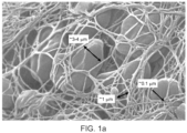
- a blood clot or thrombus ( Figure 1a ) includes a fibrin mesh ( Figure 1b ) with entrapped blood cells and platelets.
- the fibrin mesh serves as the thrombus "skeleton structure" and provides stability as well as imparting a gel-like property to the blood clot.
- the fibrin fibers are organized in a 3D mesh configuration with an average pore size of 0.1 - 50 ⁇ m (microns). The fiber diameter is between 50 - 500 nanometer.
- the distribution of the projections on the surface of the extension and the shape and size of each projection must be designed to enable the following:
- the projections are preferably arranged as an array of at least 100 projections (anywhere from several hundred to several millions projections per cm 2 of surface area) spaced apart by 0.01-500 ⁇ m (microns) (at the surface-contacting base).
- the array can be of any shape (circular, triangular, square etc) and can include one or more types (shapes) of projections, in the embodiment of the claimed invention the array has a circular shape.
- a projection can be 0.001-5,000 ⁇ m (microns) in height (length from base to tip) with a uniform or varying diameter or width throughout its length. Each projection can be angled at 90 degrees or less with respect to the surface of the extension in the direction of the base, tip or sides of the extension.
- the array can include projections that are identical or different with respect to degree of angulation and/or direction of angulation.
- the projections can be simple (e.g. cylindrical rod) or complex (e.g. 'Christmas tree' or 'mushroom') in shape and can include surface coating (composition for enhancing attachment to occlusion) or surface texturing (e.g. "fractal-like” texturing, e.g. gecko-like texturing), in the embodiment of the claimed invention the projections are configures as hooks.
- the unique configuration of the extensions and projections of the present device provides several advantages in clearing occlusions in a biological vessel.
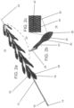
- Figures 2a illustrates a thrombus retrieval device which is referred to herein as device 10.
- Device 10 is configured suitable for entering, engaging/anchoring, dislodging and collecting thrombus material from a blood vessel and in particular small blood vessels of the brain, as well as other blood vessels.
- Device 10 includes an elongated body 12 having a handle 14 (user engaged portion) at proximal end 16 and extensions 18 (16 shown) attached to a distal portion 20.
- Elongated body 12 includes a nose cone 22 for facilitating non-traumatic delivery into a vessel and also allows penetration into the occlusion/thrombus.
- Extensions 18 are preferably arranged singly or as pairs (arrangements including 3, 4, 5, 6 or more projections are also possible) around distal portion 20, with each single or pair rotated 0 - 180 degrees from an adjacent single pair.
- Figure 2b illustrates an isolated extension 18 showing extension body 24 attached to a connector 26 via stem 27.
- Connector 26 can be glued or mechanically coupled to elongated body 12.
- connector 26 is a cylindrical connector which is fitted around elongated body 12 and fixedly attached thereto or allowed to swivel.
- Extension 18 can alternatively be connected directly to elongated body 12 without use of a connector.
- Device 10 can further include a web like element interposed between extensions 18. Such an element can supplement the ability of device 10 to capture/harvest dislodged occlusion material.
- Extension body 24 is leaf-shaped and includes an inward curving tip 28 for minimizing damage or irritation to the vessel wall when device 10 is pushed and pulled within the vessel.
- Inward curving tip 28 also functions to facilitate lodging of extensions 18 into occlusion material (e.g. thrombus material) when device 10 is pulled in a proximal direction.
- occlusion material e.g. thrombus material
- inner surface 30 of extension body 24 is concave to increase surface contact area and drag forces when the device is pulled proximally and to scoop the occlusion material dislodged from the vessel wall.
- Inner surface 30 can also be textured (e.g. micro/nano structures, not shown) to enhance surface contact area at the macro/micro/molecular level.
- Outer surface 32 of extension body 24 ( Figure 2a ) is convex to decrease drag forces when extensions 18 penetrate the thrombus mass.
- the convex outer surface 32 also allows extensions 18 to fold into a compact streamlined configuration for delivery into the vessel and occlusion. Additional hydrodynamic streamlining of extensions 18 may be effected by providing outer surface 32 with one or more bumps/protrusions/channels etc.
- Extensions 18 can be fabricated from a single material or from two or more materials.
- extensions can be molded from a single material (e.g. silicone, teflon, nylon and any other elastomer, metal alloys such as Nitinol or elastomer with combination with metal alloys such as Nitinol), with the differential rigidity provided by varying the durometer of the material (e.g. molding stem 27 and optionally connector 26 from a different structure, a silicone having a higher Shore A value or increased thickness, or by using a different material or a combination of different materials).
- a single material e.g. silicone, teflon, nylon and any other elastomer, metal alloys such as Nitinol or elastomer with combination with metal alloys such as Nitinol
- the differential rigidity provided by varying the durometer of the material (e.g. molding stem 27 and optionally connector 26 from a different structure, a silicone having a higher Shore A value or increased
- Figure 2c is a magnification of inner surface 30 of extension body 24 (of the region circled in Figure 2b ) showing array 42 including a plurality of projections 44.
- Array 42 can be attached to a smooth or textured surface (such as the textured surface described above).
- Projections 44 can be fabricated from the same material as the extensions 18, or from a different material.
- suitable materials for construction of extension 18 include silicone, teflon, nylon and any other elastomer, metal alloys such as Nitinol or elastomer with combination with metal alloys such as Nitinol.
- the projections can be attached to the surface, co formed therewith, or deposited thereupon using well known plasma deposition approaches.
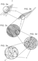
- Figures 3a-c illustrate a portion of device 10, an extension 18 thereof and a magnified view of inner surface 30 of extension 18 showing projections.
- Figure 3d-e are magnified views illustrating engagement between hook-like projections 44 and a fibrin mesh (M) component of a thrombus.
- M fibrin mesh
- Hook-like projections 44 can be 0.3-3.0 ⁇ m (microns) long, 0.2-1 ⁇ m (microns) in diameter, with a hook angle of 30-90 degrees relatively to the surface.
- the radius of curvature of the hook portion can be 0.2-1.0 ⁇ m (microns).
- projections 44 When configured as hooks, projections 44 are designed to penetrate through the openings in the fibrin mesh and hook onto the fibrin fiber when device 10 is retracted. Cooperative hooking of several projections 44 would substantially increase the engagement force between extension 18 and the thrombus mass thereby enabling retrieval of the thrombus mass when device 10 is retracted out of the vasculature.
- Figures 4a-c illustrate a portion of device 10, an extension 18 thereof and a magnified view of inner surface 30 of extension 18 showing cylindrical (rod-like) projections 44.
- Figures 4d-e are magnified views illustrating engagement between cylindrical projections 44 and a fibrin mesh component of a thrombus. Cylindrical projections 44 have a size similar to that of hook-like projections described above.
- Cylindrical projections 44 are designed to penetrate through the openings in the fibrin mesh and provide a large region of perpendicular contact between projections 44 and the fibrin fibers. Cooperative penetrations of several projections 44 through several openings in the fibrin mesh substantially increase the surface contact area and the engagement force between extension 18 and the thrombus mass thereby enabling retrieval of the thrombus mass when device 10 is retracted out of the vasculature.
- Cylindrical projections 44 preferably include surface texturing or protrusions 45 (e.g. downward-pointing protrusions, see Figures 5b, d , k, m and n ) which engage the fibrin fiber when device 10 is retracted.
- surface texturing or protrusions 45 e.g. downward-pointing protrusions, see Figures 5b, d , k, m and n .
- Figures 5a-s illustrate several embodiments of projections 44. Each embodiment is characterized by a specific configuration which facilitates engagement between projection 44 and the fibrin mesh.
- projection 44 can be configured with side or downward pointing side protrusions 45 ( Figures 5b, d and 5k-n ), a bulbous or mushroom-shaped tip ( Figure 5j ), a branching tip ( Figure 5o ), a loop-gate (e.g. 'carabiner') lock ( Figure 5p ), an upright or inverted tree-like structure ( Figure 5b, d and 5c respectively), sideward or downward projecting hair-like structures ( Figure 5s ), comb-like structure, scales, and the like.
- a projection 44 can include one or more of these structures arranged along a length thereof.
- the present device can include extensions 18 on which projections 44 are oriented in different directions, or include extensions having tips 46 (e.g. Figure 5c-d , m ) that guide projections 44 into the openings of the fibrin mesh.
- This structural asymmetry of an array 42 enables engagement with the mesh through one or more directions and thus can maximize engagement when the specific orientation of the fibrin mesh with respect to an extension 18 is unknown.
- device 10 typically includes a number of extensions 18, having various configurations of array 42 on several extensions 18 again maximizes the statistical probability of mesh penetration by projections 44.
- the embodiment of device 10 of Figure 2a is configured for use in clearing obstructions in a blood vessel, preferably a small brain artery that is 0.5-7 millimeter in diameter.
- elongated body 12 of device 10 is preferably 10-200 centimeter in length, 0.5-7 millimeter in diameter when in closed configuration, while extensions 18 are preferably 0.2-30 mm in length.
- the length of extension body 24 is preferably 0.1-30 mm and the width (at the widest thereof) is preferably 0.05-20 mm.
- Stem portion 27 is preferably 0.1-20 mm in length and 0.02-20 mm in width (at the base).
- Extensions 18 can be folded against elongated body 12 to an overall diameter of 0.5-7 millimeter. When folded, device 10 can be packed into a 1.5-22 F sheath for delivery through an access site. Once pushed out of the sheath, extensions 18 are folded outward to a position constrained by stem portion 27 (or vessel wall) while distal portion 20 is advanced to the site of occlusion. Since extension body 24 includes a non-traumatic tip 28 (fabricated from a soft material such as silicone), advancing device 10 in the distal direction (towards occlusion) does not traumatize or irritate the vessel wall. Once in position, pulling on handle/proximal catheter part 14 deploys extensions 18 to an angle limited by stem portions 27 or the vessel wall. Such an angle can be 90 degrees or les, preferably 30-45 degrees. At such an angle, tip 28 is angled inward to eliminate trauma and irritation to vessel wall.
- a non-traumatic tip 28 fabricated from a soft material such as silicone
- extensions 18 permits the device to automatically adapt to the inner diameter of the blood vessel in which device 10 is situated.
- Stem portion 27 and/or extension body 24 can also be configured such that when folded against elongated body 12, the longitudinal axis of extension body 24 is angled with respect to the longitudinal axis of elongated body 12. This increases the exposure of inner surface 30 to the biological fluid in the vessel and to the occlusion material and increases drag and likelihood of deployment when device 10 is pulled in a proximal direction.
- a roll angle can also be added such that each extension 18 has an "angle of attack" relative to the movement vector (angle range 0-90 degrees) i.e. to the anterior edge of extension body 24 relative to movement of device 10.
- the angle of attack in the forward motion (when device 10 is pushed towards occlusion) will have hydrodynamic features and a curve design that will ensure an ability to optimally penetrate and minimally disrupt the thrombus structure.
- the angle of attack (which is the opposite edge) can be shaped in a more acute curve structure in order to allow optimal drag forces of the thrombus on each extension 18 thereby ensuring opening thereof.
- Extensions 18 can also be configured to spiral around elongated body 12.
- extensions 18 and of projections 44 can be configured according to the biological vessel and occlusion properties. For example, there are two type of thrombus occlusions, a 'red' thrombus (fresh, acute whole blood thrombus) and a 'white' thrombus (relatively chronic embedded with cholesterol and calcium). Extensions 18 of device 10 as well as projections 44 can be configured with rigidity properties that match the viscosity ranges of the thrombus.
- device 10 When configured as a catheter, device 10 includes a lumen for accepting a guidewire for guiding device 10 to a target occlusion within a vessel.
- the lumen can traverse the entire length of elongated body 12 (when use with an over-the-wire system) to an guidewire inlet opening in a proximal end of elongated body or alternatively, lumen can traverse a portion thereof (when used with a rapid exchange system) to a guidewire inlet opening at a side wall along a length of elongated body 12.
- the lumen can also include one or more holes or other opening along a portion of elongated body proximal to extensions 18. Such holes can be in fluid communication with an opening at distal end and would thus enable blood to flow around the occlusion mass once extensions 18 penetrate the occlusion and the distal end crosses the occlusion and is positioned at its distal side.
- delivery and navigation of device 10 can be effected without a guidewire.
- a handle 14 or proximal portion of elongated body 12 can be used to guide device 10 (whether over a wire or not) through the vessel and position distal portion 20 at a site of occlusion.
- Device 10 can also include radio-opaque markers (e.g. gold, platinum, iridium or combined with the polymer itself or other radio-opaque markers) mounted on the distal end of elongated body 12 (at distal end).
- radio-opaque markers e.g. gold, platinum, iridium or combined with the polymer itself or other radio-opaque markers
- the markers can be mounted on ends of extensions 18 (e.g. at tips 28).
- extensions 18 extend out and thus when visualized (fluoroscopy) the markers are a predetermined distance apart (e.g. several millimeters).
- distal portion 20 is positioned inside an occlusion, extensions 18 fold against elongated body 12 and thus when visualized (fluoroscopy) the distance between the markers is reduced.
- one of the markers can be mounted on a foldable wire (e.g. Nitinol, platinum, other metal alloy or polymer wires) extending radially outward from elongated body 12 while a second marker can be attached to elongated body 12.
- a foldable wire e.g. Nitinol, platinum, other metal alloy or polymer wires
- the marker wire is folded against elongated body 12 and brought into proximity to the second marker and optionally a third marker.
- the distance between the markers can be visualized (fluoroscopy) to determine the extent of folding of the extension.
- Marker material e.g. iridium or platinum
- Marker material can also be included in the material used to fabricate extensions 18 in order to facilitate identification thereof by a surgeon.
- the markers assist the clinician in determining the correct placement of device 10 within a blood vessel and indicate when distal portion 20 enters an occlusion and extensions 18 are lodged therein.
- inner surface 30 and/or projections 44 can be coated with a substance that can bind the occlusion material.
- inner surface 30 and/or projections 44 can be coated with fibrin or fibrin derivatives.
- Device 10 can be used to clear a thrombus from an artery as follows. A guide catheter or guidewire is advanced from an access site (e.g. in a femoral artery) to the carotid artery under angiography. Device 10 is then inserted over-the-wire or through the guide catheter and navigated to the site of the thrombus. The surgeon then advances the distal end of device 10 into the thrombus until the distal end of device 10 reaches the distal end of the thrombus (as visualized via the radio-opaque markers described above). The surgeon then applies a gentle pulling force on device 10 to open extensions 18 and lodge and engage/anchor them within the thrombus. The device is then pulled along with the trapped thrombus.
- a guide catheter or guidewire is advanced from an access site (e.g. in a femoral artery) to the carotid artery under angiography. Device 10 is then inserted over-the-wire or through the guide catheter and navigated to the site
- Device 10 of the present invention can also be configured for use in clearing any type of occlusion from any biological vessels.
- the present device would be designed with surface projections that match the specific architecture of the occlusion.
- Prior art devices which utilize macrostructures (e.g. hooks, bristles) to pierce through and engage the thrombus are more likely to cause embolic events since piercing through the thrombus mass can lead to thrombus disintegration.
- macrostructures e.g. hooks, bristles
- the present device encapsulates the thrombus and externally engages it through numerous points of contact using texture-specific micro and nano structures positioned on the surface of leaf-like extensions.
- engagement of the thrombus mass does not compromise the integrity of the thrombus and use thereof may not require additional use of embolic protection or entrapment devices such as aspirators and traps which complicate and lengthen the procedure and can lead to serious complications such as vessel injury.
- OWL MC-2 old World Labs
- OWL MC-2 old World Labs
- additive manufacturing provides several advantages in manufacturing of the present device:
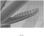
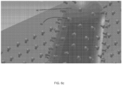
- Figures 6a-c illustrate a configuration of the present device which is optimized for additive manufacturing.
- the portion of the device shown in Figure 6a includes a tube with 6 pairs of extensions (leaves).
- the tube and extensions are printed as a mono-structure and can be connected to a microcatheter for use (carrier tube can be fitted over a microcatheter).
- carrier tube can be fitted over a microcatheter.
- This specific design is optimized for removing occlusions in 2.5 mm blood vessels.
- the extension pairs are rotationally offset 90 degrees from each other to ensure optimized occlusion engagement and collection.
- the inner surface of each extension is manufactured with projections (44) which are conical in shape and are randomly yet homogenously distributed on the surface ( Figure 6b ). Since these projections are 3D printed (along with the extension and carrier tube), exact structure and dimensions can be achieved.
- each projection is 'printed' with surface protrusions (45) which are mushroom-shaped (stalk and cap with rounded mushroom 'cap') and are 4 microns in height, 2 ⁇ m (microns) in diameter (at base) and 3 ⁇ m (microns) in diameter (at top). Average distance between protrusions is 10 ⁇ m (microns).
- the size and shape parameters of the device shown in Figures 6a-c can be varied according to the occlusive material and patient.
- Occluding materials e.g. blood clot in its various types, biological stones, foreign body and more
- the size of the occluded vessel also varies from patient to patient.
- the overall shape and size of the device as well as the shape and size of the extensions, projections and protrusions can be matched to the patient and/or occlusion.
- the size of the vessel (diameter) and the shape, size and texture of the occlusive material can be determined from noninvasive imaging (including CT, MRI, Ultra Sound, Nuclear medicine and more); sampling (biopsy, microscopy) can be used to determine the composition of the occlusive material.
- noninvasive imaging including CT, MRI, Ultra Sound, Nuclear medicine and more
- sampling biopsy, microscopy
- a suitable matching device design will be generated (including size and geometrical configuration or extensions, projections and protrusions) and printed using additive manufacturing.
- This approach could be used in real time in a hospital setting to manufacture and employ a patient-specific device optimized for retrieving a specific occlusion in a specific vessel.
Landscapes
- Health & Medical Sciences (AREA)
- Surgery (AREA)
- Life Sciences & Earth Sciences (AREA)
- Heart & Thoracic Surgery (AREA)
- Nuclear Medicine, Radiotherapy & Molecular Imaging (AREA)
- Vascular Medicine (AREA)
- Engineering & Computer Science (AREA)
- Biomedical Technology (AREA)
- Orthopedic Medicine & Surgery (AREA)
- Medical Informatics (AREA)
- Molecular Biology (AREA)
- Animal Behavior & Ethology (AREA)
- General Health & Medical Sciences (AREA)
- Public Health (AREA)
- Veterinary Medicine (AREA)
- Surgical Instruments (AREA)
Applications Claiming Priority (2)
| Application Number | Priority Date | Filing Date | Title |
|---|---|---|---|
| US201562108602P | 2015-01-28 | 2015-01-28 | |
| PCT/IL2016/050073 WO2016120864A2 (en) | 2015-01-28 | 2016-01-25 | Device and method for removing occlusions in a biological vessel |
Publications (4)
| Publication Number | Publication Date |
|---|---|
| EP3250132A2 EP3250132A2 (en) | 2017-12-06 |
| EP3250132A4 EP3250132A4 (en) | 2018-09-26 |
| EP3250132B1 true EP3250132B1 (en) | 2024-08-14 |
| EP3250132C0 EP3250132C0 (en) | 2024-08-14 |
Family
ID=56544496
Family Applications (1)
| Application Number | Title | Priority Date | Filing Date |
|---|---|---|---|
| EP16742884.6A Active EP3250132B1 (en) | 2015-01-28 | 2016-01-25 | Device for removing occlusions in a biological vessel |
Country Status (8)
Families Citing this family (14)
| Publication number | Priority date | Publication date | Assignee | Title |
|---|---|---|---|---|
| MX2014008474A (es) | 2012-01-15 | 2015-07-17 | Triticum Ltd | Dispositivo y metodo para remover oclusiones en un vaso biologico. |
| ES2998017T3 (en) | 2015-01-28 | 2025-02-18 | Triticum Ltd | Device for removing occlusions in a biological vessel |
| WO2017147493A1 (en) | 2016-02-24 | 2017-08-31 | Incept, Llc | Enhanced flexibility neurovascular catheter |
| US11471582B2 (en) | 2018-07-06 | 2022-10-18 | Incept, Llc | Vacuum transfer tool for extendable catheter |
| CN109875642A (zh) * | 2019-03-11 | 2019-06-14 | 恩脉(上海)医疗科技有限公司 | 一种取栓装置 |
| US11766539B2 (en) | 2019-03-29 | 2023-09-26 | Incept, Llc | Enhanced flexibility neurovascular catheter |
| US11633272B2 (en) | 2019-12-18 | 2023-04-25 | Imperative Care, Inc. | Manually rotatable thrombus engagement tool |
| US20230248502A1 (en) | 2019-12-18 | 2023-08-10 | Imperative Care, Inc. | Sterile field clot capture module for use in thrombectomy system |
| US11896250B2 (en) | 2020-08-31 | 2024-02-13 | Covidien Lp | Aspiration systems and methods, and expanding-mouth catheters |
| US11927002B2 (en) * | 2021-04-23 | 2024-03-12 | Kamran Yazdani | Hair entrapment filter system |
| US20230052862A1 (en) | 2021-08-12 | 2023-02-16 | Imperative Care, Inc. | Sterile packaging assembly for robotic interventional device |
| USD1077996S1 (en) | 2021-10-18 | 2025-06-03 | Imperative Care, Inc. | Inline fluid filter |
| CN114403983A (zh) * | 2021-12-22 | 2022-04-29 | 江苏大学 | 一种取栓装置及其设计方法 |
| US12171917B1 (en) | 2024-01-08 | 2024-12-24 | Imperative Care, Inc. | Devices for blood capture and reintroduction during aspiration procedure |
Family Cites Families (78)
| Publication number | Priority date | Publication date | Assignee | Title |
|---|---|---|---|---|
| US4643184A (en) | 1982-09-29 | 1987-02-17 | Mobin Uddin Kazi | Embolus trap |
| US4765332A (en) | 1986-07-14 | 1988-08-23 | Medinnovations, Inc. | Pullback atherectomy catheter system |
| FR2617720A1 (fr) | 1987-07-08 | 1989-01-13 | Medipro | Dispositif de desobstruction des sondes d'intubation et des canules de tracheotomie in vivo |
| US5009659A (en) | 1989-10-30 | 1991-04-23 | Schneider (Usa) Inc. | Fiber tip atherectomy catheter |
| GB2238485B (en) | 1989-11-28 | 1993-07-14 | Cook William Europ | A collapsible filter for introduction in a blood vessel of a patient |
| US5421832A (en) | 1989-12-13 | 1995-06-06 | Lefebvre; Jean-Marie | Filter-catheter and method of manufacturing same |
| US5192290A (en) | 1990-08-29 | 1993-03-09 | Applied Medical Resources, Inc. | Embolectomy catheter |
| US5129910A (en) | 1991-07-26 | 1992-07-14 | The Regents Of The University Of California | Stone expulsion stent |
| CH685738A5 (fr) | 1993-03-25 | 1995-09-29 | Ferromec Sa | Instrument médical pour l'élimination de dépôts formés sur les parois intérieures des artères ou des veines. |
| WO1994023787A1 (en) | 1993-04-22 | 1994-10-27 | Rammler David H | Sampling balloon catheter |
| US5370653A (en) | 1993-07-22 | 1994-12-06 | Micro Therapeutics, Inc. | Thrombectomy method and apparatus |
| US5769960A (en) | 1995-07-05 | 1998-06-23 | Nirmel; Chittaranjan N. | Device and method for manually removing a clog containing fibrous matter |
| US5827304A (en) | 1995-11-16 | 1998-10-27 | Applied Medical Resources Corporation | Intraluminal extraction catheter |
| US5702413A (en) | 1996-01-11 | 1997-12-30 | Scimed Life Systems, Inc. | Curved bristle atherectomy device and method |
| WO1997027893A1 (en) | 1996-02-02 | 1997-08-07 | Transvascular, Inc. | Methods and apparatus for blocking flow through blood vessels |
| US6254571B1 (en) | 1996-04-18 | 2001-07-03 | Applied Medical Resources Corporation | Remote clot management |
| US5882329A (en) | 1997-02-12 | 1999-03-16 | Prolifix Medical, Inc. | Apparatus and method for removing stenotic material from stents |
| US5895400A (en) | 1997-06-27 | 1999-04-20 | Abela; George S. | Catheter with bristles |
| US5984965A (en) | 1997-08-28 | 1999-11-16 | Urosurge, Inc. | Anti-reflux reinforced stent |
| US5836032A (en) | 1997-09-30 | 1998-11-17 | Hondo; Leslie H. | Apparatus for removing hair from a drain |
| US6027514A (en) | 1997-12-17 | 2000-02-22 | Fox Hollow Technologies, Inc. | Apparatus and method for removing occluding material from body lumens |
| US6725492B2 (en) | 1998-11-25 | 2004-04-27 | Neosci Medical, Inc. | Cleaning brush for medical devices |
| US6350271B1 (en) | 1999-05-17 | 2002-02-26 | Micrus Corporation | Clot retrieval device |
| US6458139B1 (en) | 1999-06-21 | 2002-10-01 | Endovascular Technologies, Inc. | Filter/emboli extractor for use in variable sized blood vessels |
| USD435944S1 (en) | 2000-02-09 | 2001-01-02 | Eugene H. Luoma | Drain cleaner strip |
| US6775873B2 (en) | 2000-02-09 | 2004-08-17 | Eugene H. Luoma | Apparatus for removing hair from a drain |
| US8298257B2 (en) | 2000-06-29 | 2012-10-30 | Concentric Medical, Inc. | Systems, methods and devices for removing obstructions from a blood vessel |
| US7727242B2 (en) | 2000-06-29 | 2010-06-01 | Concentric Medical, Inc. | Systems, methods and devices for removing obstructions from a blood vessel |
| US6663650B2 (en) | 2000-06-29 | 2003-12-16 | Concentric Medical, Inc. | Systems, methods and devices for removing obstructions from a blood vessel |
| ES2370109T3 (es) | 2001-01-09 | 2011-12-12 | Microvention, Inc. | Catéteres de embolectomía. |
| US6800083B2 (en) | 2001-04-09 | 2004-10-05 | Scimed Life Systems, Inc. | Compressible atherectomy burr |
| JP4567918B2 (ja) | 2001-07-02 | 2010-10-27 | テルモ株式会社 | 血管内異物除去用ワイヤおよび医療器具 |
| JP2003038500A (ja) | 2001-08-03 | 2003-02-12 | Mti Kk | 管状器官内の異物除去用ブラシつきシャフト |
| US20040215222A1 (en) | 2003-04-25 | 2004-10-28 | Michael Krivoruchko | Intravascular material removal device |
| US20070118165A1 (en) | 2004-03-08 | 2007-05-24 | Demello Jonathan R | System and method for removal of material from a blood vessel using a small diameter catheter |
| ES2323273T3 (es) | 2004-03-31 | 2009-07-10 | Orthofix S.R.L. | Clavo intramedular que comprende elementos de material con memoria de forma. |
| IL161554A0 (en) | 2004-04-22 | 2004-09-27 | Gali Tech Ltd | Catheter |
| US8241315B2 (en) | 2004-06-24 | 2012-08-14 | Boston Scientific Scimed, Inc. | Apparatus and method for treating occluded vasculature |
| DE102004040868A1 (de) * | 2004-08-23 | 2006-03-09 | Miloslavski, Elina | Vorrichtung zur Entfernung von Thromben |
| US20060058837A1 (en) | 2004-09-10 | 2006-03-16 | Arani Bose | System and method for treating ischemic stroke |
| WO2006084256A2 (en) | 2005-02-02 | 2006-08-10 | Peacock James C | Total vascular occlusion treatment system and method |
| US20060184194A1 (en) | 2005-02-15 | 2006-08-17 | Cook Incorporated | Embolic protection device |
| USD532978S1 (en) | 2005-02-16 | 2006-12-05 | Marie Robinson | Flexible compressible brush for cleaning drinking straws |
| US7731731B2 (en) * | 2005-06-17 | 2010-06-08 | Abela George S | Catheter for clearing passages in a patient |
| US8734362B2 (en) | 2005-07-26 | 2014-05-27 | Edward M. Boyle, JR. | Minimally invasive methods and apparatus |
| US8377092B2 (en) | 2005-09-16 | 2013-02-19 | Cook Medical Technologies Llc | Embolic protection device |
| US7914549B2 (en) * | 2007-01-05 | 2011-03-29 | Hesham Morsi | Mechanical embolectomy and suction catheter |
| US9138307B2 (en) | 2007-09-14 | 2015-09-22 | Cook Medical Technologies Llc | Expandable device for treatment of a stricture in a body vessel |
| US20090112239A1 (en) * | 2007-10-31 | 2009-04-30 | Specialized Vascular Technologies, Inc. | Sticky dilatation balloon and methods of using |
| US20150164630A1 (en) * | 2008-01-04 | 2015-06-18 | Eric Johnson | Filter support members |
| US8021379B2 (en) | 2008-01-11 | 2011-09-20 | Medtronic Vascular, Inc. | Obstruction removal system |
| US8021380B2 (en) | 2008-01-11 | 2011-09-20 | Dustin Thompson | Obstruction removal system |
| GB2459481A (en) | 2008-04-23 | 2009-10-28 | Invivo Technology Ltd | Expanding medical collet |
| US8939991B2 (en) | 2008-06-08 | 2015-01-27 | Hotspur Technologies, Inc. | Apparatus and methods for removing obstructive material from body lumens |
| CA2732787C (en) | 2008-08-08 | 2017-04-18 | Incept, Llc | Apparatus and methods for accessing and removing material from body lumens |
| US8034095B2 (en) | 2008-08-29 | 2011-10-11 | Cook Medical Technologies Llc | Intraluminal system for retrieving an implantable medical device |
| US20100249815A1 (en) | 2009-03-25 | 2010-09-30 | Cook Incorporated | Everted sheath thrombectomy device |
| US8795304B2 (en) | 2009-06-18 | 2014-08-05 | Cardiovascular Systems, Inc. | Atherectomy device, system and method having a bi-directional distal expandable ablation element |
| USD610761S1 (en) | 2009-06-19 | 2010-02-23 | Charles Gengler | Drain unclogger |
| WO2011038315A1 (en) | 2009-09-28 | 2011-03-31 | Zimmer, Inc. | Expandable intramedullary rod |
| EP4039203A1 (en) * | 2010-04-13 | 2022-08-10 | Mivi Neuroscience, Inc. | Embolectomy devices for treatment of acute ischemic stroke condition |
| US8365337B2 (en) | 2010-07-09 | 2013-02-05 | George Tash and Debra B. Tash, As Trustees of the Community Trust | Hand-operated drain snake with auger |
| US9220499B2 (en) | 2010-10-28 | 2015-12-29 | Covidien Lp | Wound closure device including barbed pins |
| USD649724S1 (en) | 2010-12-09 | 2011-11-29 | S.C. Johnson & Son, Inc. | Wand |
| US8597170B2 (en) | 2011-01-05 | 2013-12-03 | Thoratec Corporation | Catheter pump |
| DE102011011510B4 (de) | 2011-02-17 | 2022-12-29 | Acandis Gmbh | Medizinische Vorrichtung zum Entfernen von Konkrementen und System mit einer derartigen medizinischen Vorrichtung |
| ES3029850T3 (en) * | 2011-03-09 | 2025-06-25 | Neuravi Ltd | A clot retrieval device for removing occlusive clot from a blood vessel |
| US10149697B2 (en) | 2011-10-04 | 2018-12-11 | Angioworks Medical, B.V. | Devices and methods for percutaneous tissue removal |
| MX2014008474A (es) | 2012-01-15 | 2015-07-17 | Triticum Ltd | Dispositivo y metodo para remover oclusiones en un vaso biologico. |
| WO2013116529A1 (en) | 2012-01-31 | 2013-08-08 | The Trustees Of Columbia University In The City Of New York | Sampling catheter devices, methods, and systems |
| US20140090195A1 (en) | 2012-09-28 | 2014-04-03 | Kimberly-Clark Worldwide, Inc. | Self Positioning Tracheal Tube Clearance Mechanism Using Whisks |
| US8784434B2 (en) | 2012-11-20 | 2014-07-22 | Inceptus Medical, Inc. | Methods and apparatus for treating embolism |
| US9194114B2 (en) | 2013-01-08 | 2015-11-24 | Marvin Petry | Drain pipe cleaning device and method |
| WO2014179310A1 (en) | 2013-04-29 | 2014-11-06 | Regenerative Sciences, Llc | Percutaneous tendon-muscle-ligament approximation device |
| US9217243B2 (en) | 2013-05-02 | 2015-12-22 | Patrick Gwen | Drain cleaning tool |
| US9259237B2 (en) * | 2013-07-12 | 2016-02-16 | Inceptus Medical, Llc | Methods and apparatus for treating pulmonary embolism |
| ES2998017T3 (en) | 2015-01-28 | 2025-02-18 | Triticum Ltd | Device for removing occlusions in a biological vessel |
| US10072405B2 (en) | 2015-01-30 | 2018-09-11 | Pf Waterworks Lp | Drain cleaning apparatus |
-
2016
- 2016-01-25 ES ES16742884T patent/ES2998017T3/es active Active
- 2016-01-25 EP EP16742884.6A patent/EP3250132B1/en active Active
- 2016-01-25 CA CA2973125A patent/CA2973125C/en active Active
- 2016-01-25 JP JP2017540079A patent/JP6741674B2/ja active Active
- 2016-01-25 WO PCT/IL2016/050073 patent/WO2016120864A2/en active Application Filing
- 2016-01-25 CN CN201680019053.5A patent/CN107405140B/zh active Active
- 2016-01-25 US US15/528,110 patent/US10772647B2/en active Active
-
2017
- 2017-05-11 IL IL252225A patent/IL252225B/en unknown
Non-Patent Citations (1)
| Title |
|---|
| "Polymer Adhesion, Friction, and Lubrication", 26 February 2013, JOHN WILEY & SONS, INC., online, ISBN: 978-0-470-91627-8, article MENGÜÇ YIGIT ET AL: "Gecko-Inspired Polymer Adhesives : Zeng/Polymer Adhesion, Friction, and Lubrication", pages: 351 - 389, XP055914013, DOI: 10.1002/9781118505175.ch9 * |
Also Published As
| Publication number | Publication date |
|---|---|
| CA2973125C (en) | 2023-07-04 |
| WO2016120864A3 (en) | 2016-09-22 |
| US20170311966A1 (en) | 2017-11-02 |
| JP2018503465A (ja) | 2018-02-08 |
| CN107405140B (zh) | 2021-05-11 |
| JP6741674B2 (ja) | 2020-08-19 |
| ES2998017T3 (en) | 2025-02-18 |
| IL252225B (en) | 2022-01-01 |
| EP3250132A4 (en) | 2018-09-26 |
| CN107405140A (zh) | 2017-11-28 |
| WO2016120864A2 (en) | 2016-08-04 |
| CA2973125A1 (en) | 2016-08-04 |
| US10772647B2 (en) | 2020-09-15 |
| EP3250132C0 (en) | 2024-08-14 |
| IL252225A0 (en) | 2017-07-31 |
| EP3250132A2 (en) | 2017-12-06 |
Similar Documents
| Publication | Publication Date | Title |
|---|---|---|
| EP3250132B1 (en) | Device for removing occlusions in a biological vessel | |
| JP6430674B2 (ja) | 生体管における閉塞を除去するための装置 | |
| US11925369B2 (en) | Method for treating vascular occlusion | |
| EP3579765B1 (en) | Axial lengthening thrombus capture system | |
| EP3539485B1 (en) | Small fragment retrieval device | |
| US9101449B2 (en) | Filter removal device |
Legal Events
| Date | Code | Title | Description |
|---|---|---|---|
| STAA | Information on the status of an ep patent application or granted ep patent |
Free format text: STATUS: THE INTERNATIONAL PUBLICATION HAS BEEN MADE |
|
| PUAI | Public reference made under article 153(3) epc to a published international application that has entered the european phase |
Free format text: ORIGINAL CODE: 0009012 |
|
| STAA | Information on the status of an ep patent application or granted ep patent |
Free format text: STATUS: REQUEST FOR EXAMINATION WAS MADE |
|
| 17P | Request for examination filed |
Effective date: 20170713 |
|
| AK | Designated contracting states |
Kind code of ref document: A2 Designated state(s): AL AT BE BG CH CY CZ DE DK EE ES FI FR GB GR HR HU IE IS IT LI LT LU LV MC MK MT NL NO PL PT RO RS SE SI SK SM TR |
|
| AX | Request for extension of the european patent |
Extension state: BA ME |
|
| DAV | Request for validation of the european patent (deleted) | ||
| DAX | Request for extension of the european patent (deleted) | ||
| A4 | Supplementary search report drawn up and despatched |
Effective date: 20180824 |
|
| RIC1 | Information provided on ipc code assigned before grant |
Ipc: A61B 17/00 20060101AFI20180820BHEP Ipc: A61B 17/22 20060101ALI20180820BHEP Ipc: A61B 17/32 20060101ALN20180820BHEP |
|
| STAA | Information on the status of an ep patent application or granted ep patent |
Free format text: STATUS: EXAMINATION IS IN PROGRESS |
|
| 17Q | First examination report despatched |
Effective date: 20220426 |
|
| P01 | Opt-out of the competence of the unified patent court (upc) registered |
Effective date: 20230527 |
|
| RIC1 | Information provided on ipc code assigned before grant |
Ipc: A61B 17/32 20060101ALN20240214BHEP Ipc: A61B 17/22 20060101ALI20240214BHEP Ipc: A61B 17/00 20060101AFI20240214BHEP |
|
| GRAP | Despatch of communication of intention to grant a patent |
Free format text: ORIGINAL CODE: EPIDOSNIGR1 |
|
| STAA | Information on the status of an ep patent application or granted ep patent |
Free format text: STATUS: GRANT OF PATENT IS INTENDED |
|
| RIC1 | Information provided on ipc code assigned before grant |
Ipc: A61B 17/32 20060101ALN20240321BHEP Ipc: A61B 17/22 20060101ALI20240321BHEP Ipc: A61B 17/00 20060101AFI20240321BHEP |
|
| INTG | Intention to grant announced |
Effective date: 20240411 |
|
| GRAS | Grant fee paid |
Free format text: ORIGINAL CODE: EPIDOSNIGR3 |
|
| GRAA | (expected) grant |
Free format text: ORIGINAL CODE: 0009210 |
|
| STAA | Information on the status of an ep patent application or granted ep patent |
Free format text: STATUS: THE PATENT HAS BEEN GRANTED |
|
| AK | Designated contracting states |
Kind code of ref document: B1 Designated state(s): AL AT BE BG CH CY CZ DE DK EE ES FI FR GB GR HR HU IE IS IT LI LT LU LV MC MK MT NL NO PL PT RO RS SE SI SK SM TR |
|
| REG | Reference to a national code |
Ref country code: GB Ref legal event code: FG4D |
|
| REG | Reference to a national code |
Ref country code: CH Ref legal event code: EP |
|
| REG | Reference to a national code |
Ref country code: DE Ref legal event code: R096 Ref document number: 602016088880 Country of ref document: DE |
|
| REG | Reference to a national code |
Ref country code: IE Ref legal event code: FG4D |
|
| U01 | Request for unitary effect filed |
Effective date: 20240913 |
|
| U07 | Unitary effect registered |
Designated state(s): AT BE BG DE DK EE FI FR IT LT LU LV MT NL PT RO SE SI Effective date: 20241002 |
|
| PG25 | Lapsed in a contracting state [announced via postgrant information from national office to epo] |
Ref country code: NO Free format text: LAPSE BECAUSE OF FAILURE TO SUBMIT A TRANSLATION OF THE DESCRIPTION OR TO PAY THE FEE WITHIN THE PRESCRIBED TIME-LIMIT Effective date: 20241114 |
|
| PG25 | Lapsed in a contracting state [announced via postgrant information from national office to epo] |
Ref country code: PL Free format text: LAPSE BECAUSE OF FAILURE TO SUBMIT A TRANSLATION OF THE DESCRIPTION OR TO PAY THE FEE WITHIN THE PRESCRIBED TIME-LIMIT Effective date: 20240814 Ref country code: GR Free format text: LAPSE BECAUSE OF FAILURE TO SUBMIT A TRANSLATION OF THE DESCRIPTION OR TO PAY THE FEE WITHIN THE PRESCRIBED TIME-LIMIT Effective date: 20241115 |
|
| PG25 | Lapsed in a contracting state [announced via postgrant information from national office to epo] |
Ref country code: IS Free format text: LAPSE BECAUSE OF FAILURE TO SUBMIT A TRANSLATION OF THE DESCRIPTION OR TO PAY THE FEE WITHIN THE PRESCRIBED TIME-LIMIT Effective date: 20241214 |
|
| PG25 | Lapsed in a contracting state [announced via postgrant information from national office to epo] |
Ref country code: HR Free format text: LAPSE BECAUSE OF FAILURE TO SUBMIT A TRANSLATION OF THE DESCRIPTION OR TO PAY THE FEE WITHIN THE PRESCRIBED TIME-LIMIT Effective date: 20240814 |
|
| PG25 | Lapsed in a contracting state [announced via postgrant information from national office to epo] |
Ref country code: RS Free format text: LAPSE BECAUSE OF FAILURE TO SUBMIT A TRANSLATION OF THE DESCRIPTION OR TO PAY THE FEE WITHIN THE PRESCRIBED TIME-LIMIT Effective date: 20241114 |
|
| PG25 | Lapsed in a contracting state [announced via postgrant information from national office to epo] |
Ref country code: RS Free format text: LAPSE BECAUSE OF FAILURE TO SUBMIT A TRANSLATION OF THE DESCRIPTION OR TO PAY THE FEE WITHIN THE PRESCRIBED TIME-LIMIT Effective date: 20241114 Ref country code: PL Free format text: LAPSE BECAUSE OF FAILURE TO SUBMIT A TRANSLATION OF THE DESCRIPTION OR TO PAY THE FEE WITHIN THE PRESCRIBED TIME-LIMIT Effective date: 20240814 Ref country code: NO Free format text: LAPSE BECAUSE OF FAILURE TO SUBMIT A TRANSLATION OF THE DESCRIPTION OR TO PAY THE FEE WITHIN THE PRESCRIBED TIME-LIMIT Effective date: 20241114 Ref country code: IS Free format text: LAPSE BECAUSE OF FAILURE TO SUBMIT A TRANSLATION OF THE DESCRIPTION OR TO PAY THE FEE WITHIN THE PRESCRIBED TIME-LIMIT Effective date: 20241214 Ref country code: HR Free format text: LAPSE BECAUSE OF FAILURE TO SUBMIT A TRANSLATION OF THE DESCRIPTION OR TO PAY THE FEE WITHIN THE PRESCRIBED TIME-LIMIT Effective date: 20240814 Ref country code: GR Free format text: LAPSE BECAUSE OF FAILURE TO SUBMIT A TRANSLATION OF THE DESCRIPTION OR TO PAY THE FEE WITHIN THE PRESCRIBED TIME-LIMIT Effective date: 20241115 |
|
| REG | Reference to a national code |
Ref country code: ES Ref legal event code: FG2A Ref document number: 2998017 Country of ref document: ES Kind code of ref document: T3 Effective date: 20250218 |
|
| U20 | Renewal fee for the european patent with unitary effect paid |
Year of fee payment: 10 Effective date: 20250128 |
|
| PG25 | Lapsed in a contracting state [announced via postgrant information from national office to epo] |
Ref country code: SM Free format text: LAPSE BECAUSE OF FAILURE TO SUBMIT A TRANSLATION OF THE DESCRIPTION OR TO PAY THE FEE WITHIN THE PRESCRIBED TIME-LIMIT Effective date: 20240814 |
|
| PGFP | Annual fee paid to national office [announced via postgrant information from national office to epo] |
Ref country code: ES Payment date: 20250226 Year of fee payment: 10 |
|
| PG25 | Lapsed in a contracting state [announced via postgrant information from national office to epo] |
Ref country code: CZ Free format text: LAPSE BECAUSE OF FAILURE TO SUBMIT A TRANSLATION OF THE DESCRIPTION OR TO PAY THE FEE WITHIN THE PRESCRIBED TIME-LIMIT Effective date: 20240814 |
|
| PG25 | Lapsed in a contracting state [announced via postgrant information from national office to epo] |
Ref country code: SK Free format text: LAPSE BECAUSE OF FAILURE TO SUBMIT A TRANSLATION OF THE DESCRIPTION OR TO PAY THE FEE WITHIN THE PRESCRIBED TIME-LIMIT Effective date: 20240814 |
|
| PGFP | Annual fee paid to national office [announced via postgrant information from national office to epo] |
Ref country code: GB Payment date: 20250128 Year of fee payment: 10 |
|
| PLBE | No opposition filed within time limit |
Free format text: ORIGINAL CODE: 0009261 |
|
| STAA | Information on the status of an ep patent application or granted ep patent |
Free format text: STATUS: NO OPPOSITION FILED WITHIN TIME LIMIT |
|
| 26N | No opposition filed |
Effective date: 20250515 |
|
| REG | Reference to a national code |
Ref country code: CH Ref legal event code: PL |