EP3249668B1 - Electric energy storage device having improved installation structure of internal terminal - Google Patents
Electric energy storage device having improved installation structure of internal terminal Download PDFInfo
- Publication number
- EP3249668B1 EP3249668B1 EP16740336.9A EP16740336A EP3249668B1 EP 3249668 B1 EP3249668 B1 EP 3249668B1 EP 16740336 A EP16740336 A EP 16740336A EP 3249668 B1 EP3249668 B1 EP 3249668B1
- Authority
- EP
- European Patent Office
- Prior art keywords
- terminal
- positive electrode
- metal case
- internal terminal
- flange
- Prior art date
- Legal status (The legal status is an assumption and is not a legal conclusion. Google has not performed a legal analysis and makes no representation as to the accuracy of the status listed.)
- Active
Links
Images


Classifications
-
- H—ELECTRICITY
- H01—ELECTRIC ELEMENTS
- H01G—CAPACITORS; CAPACITORS, RECTIFIERS, DETECTORS, SWITCHING DEVICES, LIGHT-SENSITIVE OR TEMPERATURE-SENSITIVE DEVICES OF THE ELECTROLYTIC TYPE
- H01G11/00—Hybrid capacitors, i.e. capacitors having different positive and negative electrodes; Electric double-layer [EDL] capacitors; Processes for the manufacture thereof or of parts thereof
- H01G11/74—Terminals, e.g. extensions of current collectors
-
- H—ELECTRICITY
- H01—ELECTRIC ELEMENTS
- H01G—CAPACITORS; CAPACITORS, RECTIFIERS, DETECTORS, SWITCHING DEVICES, LIGHT-SENSITIVE OR TEMPERATURE-SENSITIVE DEVICES OF THE ELECTROLYTIC TYPE
- H01G11/00—Hybrid capacitors, i.e. capacitors having different positive and negative electrodes; Electric double-layer [EDL] capacitors; Processes for the manufacture thereof or of parts thereof
- H01G11/78—Cases; Housings; Encapsulations; Mountings
- H01G11/82—Fixing or assembling a capacitive element in a housing, e.g. mounting electrodes, current collectors or terminals in containers or encapsulations
-
- H—ELECTRICITY
- H01—ELECTRIC ELEMENTS
- H01G—CAPACITORS; CAPACITORS, RECTIFIERS, DETECTORS, SWITCHING DEVICES, LIGHT-SENSITIVE OR TEMPERATURE-SENSITIVE DEVICES OF THE ELECTROLYTIC TYPE
- H01G4/00—Fixed capacitors; Processes of their manufacture
- H01G4/002—Details
- H01G4/228—Terminals
- H01G4/232—Terminals electrically connecting two or more layers of a stacked or rolled capacitor
-
- H—ELECTRICITY
- H01—ELECTRIC ELEMENTS
- H01G—CAPACITORS; CAPACITORS, RECTIFIERS, DETECTORS, SWITCHING DEVICES, LIGHT-SENSITIVE OR TEMPERATURE-SENSITIVE DEVICES OF THE ELECTROLYTIC TYPE
- H01G4/00—Fixed capacitors; Processes of their manufacture
- H01G4/32—Wound capacitors
-
- H—ELECTRICITY
- H01—ELECTRIC ELEMENTS
- H01G—CAPACITORS; CAPACITORS, RECTIFIERS, DETECTORS, SWITCHING DEVICES, LIGHT-SENSITIVE OR TEMPERATURE-SENSITIVE DEVICES OF THE ELECTROLYTIC TYPE
- H01G9/00—Electrolytic capacitors, rectifiers, detectors, switching devices, light-sensitive or temperature-sensitive devices; Processes of their manufacture
- H01G9/004—Details
- H01G9/008—Terminals
-
- H—ELECTRICITY
- H01—ELECTRIC ELEMENTS
- H01G—CAPACITORS; CAPACITORS, RECTIFIERS, DETECTORS, SWITCHING DEVICES, LIGHT-SENSITIVE OR TEMPERATURE-SENSITIVE DEVICES OF THE ELECTROLYTIC TYPE
- H01G9/00—Electrolytic capacitors, rectifiers, detectors, switching devices, light-sensitive or temperature-sensitive devices; Processes of their manufacture
- H01G9/004—Details
- H01G9/08—Housing; Encapsulation
-
- H—ELECTRICITY
- H01—ELECTRIC ELEMENTS
- H01G—CAPACITORS; CAPACITORS, RECTIFIERS, DETECTORS, SWITCHING DEVICES, LIGHT-SENSITIVE OR TEMPERATURE-SENSITIVE DEVICES OF THE ELECTROLYTIC TYPE
- H01G9/00—Electrolytic capacitors, rectifiers, detectors, switching devices, light-sensitive or temperature-sensitive devices; Processes of their manufacture
- H01G9/15—Solid electrolytic capacitors
- H01G9/151—Solid electrolytic capacitors with wound foil electrodes
-
- H—ELECTRICITY
- H01—ELECTRIC ELEMENTS
- H01M—PROCESSES OR MEANS, e.g. BATTERIES, FOR THE DIRECT CONVERSION OF CHEMICAL ENERGY INTO ELECTRICAL ENERGY
- H01M50/00—Constructional details or processes of manufacture of the non-active parts of electrochemical cells other than fuel cells, e.g. hybrid cells
- H01M50/10—Primary casings; Jackets or wrappings
- H01M50/102—Primary casings; Jackets or wrappings characterised by their shape or physical structure
- H01M50/107—Primary casings; Jackets or wrappings characterised by their shape or physical structure having curved cross-section, e.g. round or elliptic
-
- Y—GENERAL TAGGING OF NEW TECHNOLOGICAL DEVELOPMENTS; GENERAL TAGGING OF CROSS-SECTIONAL TECHNOLOGIES SPANNING OVER SEVERAL SECTIONS OF THE IPC; TECHNICAL SUBJECTS COVERED BY FORMER USPC CROSS-REFERENCE ART COLLECTIONS [XRACs] AND DIGESTS
- Y02—TECHNOLOGIES OR APPLICATIONS FOR MITIGATION OR ADAPTATION AGAINST CLIMATE CHANGE
- Y02E—REDUCTION OF GREENHOUSE GAS [GHG] EMISSIONS, RELATED TO ENERGY GENERATION, TRANSMISSION OR DISTRIBUTION
- Y02E60/00—Enabling technologies; Technologies with a potential or indirect contribution to GHG emissions mitigation
- Y02E60/10—Energy storage using batteries
-
- Y—GENERAL TAGGING OF NEW TECHNOLOGICAL DEVELOPMENTS; GENERAL TAGGING OF CROSS-SECTIONAL TECHNOLOGIES SPANNING OVER SEVERAL SECTIONS OF THE IPC; TECHNICAL SUBJECTS COVERED BY FORMER USPC CROSS-REFERENCE ART COLLECTIONS [XRACs] AND DIGESTS
- Y02—TECHNOLOGIES OR APPLICATIONS FOR MITIGATION OR ADAPTATION AGAINST CLIMATE CHANGE
- Y02E—REDUCTION OF GREENHOUSE GAS [GHG] EMISSIONS, RELATED TO ENERGY GENERATION, TRANSMISSION OR DISTRIBUTION
- Y02E60/00—Enabling technologies; Technologies with a potential or indirect contribution to GHG emissions mitigation
- Y02E60/13—Energy storage using capacitors
-
- Y—GENERAL TAGGING OF NEW TECHNOLOGICAL DEVELOPMENTS; GENERAL TAGGING OF CROSS-SECTIONAL TECHNOLOGIES SPANNING OVER SEVERAL SECTIONS OF THE IPC; TECHNICAL SUBJECTS COVERED BY FORMER USPC CROSS-REFERENCE ART COLLECTIONS [XRACs] AND DIGESTS
- Y02—TECHNOLOGIES OR APPLICATIONS FOR MITIGATION OR ADAPTATION AGAINST CLIMATE CHANGE
- Y02P—CLIMATE CHANGE MITIGATION TECHNOLOGIES IN THE PRODUCTION OR PROCESSING OF GOODS
- Y02P70/00—Climate change mitigation technologies in the production process for final industrial or consumer products
- Y02P70/50—Manufacturing or production processes characterised by the final manufactured product
-
- Y—GENERAL TAGGING OF NEW TECHNOLOGICAL DEVELOPMENTS; GENERAL TAGGING OF CROSS-SECTIONAL TECHNOLOGIES SPANNING OVER SEVERAL SECTIONS OF THE IPC; TECHNICAL SUBJECTS COVERED BY FORMER USPC CROSS-REFERENCE ART COLLECTIONS [XRACs] AND DIGESTS
- Y02—TECHNOLOGIES OR APPLICATIONS FOR MITIGATION OR ADAPTATION AGAINST CLIMATE CHANGE
- Y02T—CLIMATE CHANGE MITIGATION TECHNOLOGIES RELATED TO TRANSPORTATION
- Y02T10/00—Road transport of goods or passengers
- Y02T10/60—Other road transportation technologies with climate change mitigation effect
- Y02T10/70—Energy storage systems for electromobility, e.g. batteries
Definitions
- the present disclosure relates to an electric energy storage device, and more particularly, to an electric energy storage device having an internal terminal with an improved installation structure, connected to an electrode of a cell assembly inside a metal case.
- a high capacitance storage device which is regarded as a next-generation electric energy storage device, includes a ultra-capacitor (UC), a super capacitor (SC), an electric double layer capacitor (EDLC) and the like, which are a kind of capacitor, and it is an energy storage device having an intermediate property between an electrolytic condenser and a secondary battery, which can be used in combination with, or in place of, a secondary battery due to its high efficiency and semi-permanent life span.
- UC ultra-capacitor
- SC super capacitor
- EDLC electric double layer capacitor
- the high capacitance storage device is sometimes used in place of a battery for applications which do not ensure easy maintenance and demand long service life.
- the high capacitance storage device has fast charging/discharging characteristics and thus is very suitable not only as an auxiliary power source for mobile communication information devices such as a mobile phone, a notebook and a PDA but also as a main or auxiliary power source of an electric vehicle, a night road pilot lamp, an uninterrupted power supply (UPS) and the like, which demand high capacity, and is widely used for such purposes.
- UPS uninterrupted power supply
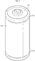
- the high capacitance storage device generally has a cylindrical shape as shown in FIG. 1 for a small size.
- a high capacitance storage device includes a cell assembly 1 composed of a positive electrode, a negative electrode, a separator and an electrolyte and contained in an inner housing, a metal case 4 accommodating the cell assembly 1, and a negative electrode internal terminal 2 and a positive electrode internal terminal 3 substantially having a plate shape and respectively connected to upper and lower portions of the metal case 4 and connected to a negative electrode and a positive electrode of the cell assembly 1.
- the negative electrode inner terminal 2 is insulated against the metal case 4 by an insulation member 6 and simultaneously contacts a top plate 5, and the positive inner terminal 3 is in contact with the metal case 4.
- Terminal units 8, 9 are generally formed to protrude at a center of the top plate 5 and a bottom center of the metal case 4.
- the coupling between the negative electrode internal terminal 2 and the top plate 5 and the coupling between the positive electrode internal terminal 3 and the metal case 4 are usually made by a coupling bolt 7.
- the negative electrode internal terminal 2 and the top plate 5 are heavy and bulky, which demands structural improvements.
- the negative electrode internal terminal 2 and the positive electrode internal terminal 3 may be coupled to the metal case 4 by performing a beading process to the metal case 4.
- a predetermined groove (not shown) is formed along the outer circumference of the negative electrode internal terminal 2 and the positive electrode internal terminal 3, and a protruding portion of the metal case 4 protruding inwards is interposed into the groove by means of the beading process performed to the metal case 4, thereby fixing the internal terminal to the metal case 4.
- the groove should be formed at the outer circumference of the internal terminals 2, 3 to correspond to the width of the protruding portion formed by the beading process, and thus there is a limitation in reducing the thickness of the metal case 4, which makes it difficult to expand the inner space of the metal case 4. If the inner space of the metal case 4 is not sufficiently secured, the internal pressure may be increased.
- a side reaction occurs at an interface between an electrolyte and an electrode when an abnormal operation such as overcharge, overdischarge and overvoltage takes place at room temperature, thereby generating gas as a byproduct. If the gas is generated and accumulated inside, the internal pressure of the metal case 4 continuously increases, and eventually the metal case 4 is swelled convexly or gas is discharged abruptly at a weak portion of the metal case 4 to cause explosion.
- a curling portion 10 bent toward the top plate 5 is formed at the upper end of the metal case 4 so that the pressure resistance performance may be easily enhanced by controlling the curling amount.
- it is very important to sufficiently secure the inner space of the metal case 4.
- Examples of electric energy storage devices according to the prior art are known from CN 202887989 , US 2012/229954 and CN 103680999 .
- the present disclosure is designed to solve the problems of the related art, and therefore the present disclosure is directed to providing an electric energy storage device in which a structure for installing an internal terminal to a metal case is improved so that an internal terminal with a simplified structure in a thin form may be provided inside the metal case.
- the present disclosure is also directed to providing an electric energy storage device having a structure capable of sufficiently reducing an internal pressure of the metal case by sufficiently securing an inner space therein.
- the present disclosure is also directed to providing an electric energy storage device having a low resistance characteristic since an outer circumferential end of the internal terminal is closely adhered to an inner wall of the metal case.
- the present invention relates to an electric current storage device according to claim 1.
- an electric energy storage device which includes a positive electrode internal terminal composed of a plate-shaped terminal body having at least one electrolyte impregnation hole formed therein and a flange, wherein an upper surface of the terminal body and any one surface of the flange come into contact with a cell assembly to couple the positive electrode internal terminal and the cell assembly, wherein a lower surface of the terminal body comes into contact with an inner surface of a lower end of a case, and wherein the flange is pressed by a terminal-fixing beading portion so that the positive electrode internal terminal is fixed in the case.
- the flange may be formed at an outer circumference of the terminal body to extend upwards.
- One surface of the flange may be pressed by the terminal-fixing beading portion, and the other surface of the flange may be supported by the cell assembly, so that the flange is closely adhered and fixed at the inside of the case.
- An upper edge of the terminal-fixing beading portion may be located higher than a top end of the flange so that the terminal-fixing beading portion presses the flange.
- an electric energy storage device which includes a positive electrode internal terminal composed of a plate-shaped terminal body having at least one electrolyte impregnation hole formed therein, wherein a lower surface of the terminal body of the positive electrode internal terminal comes into contact with an inner surface of a lower end of a case, and an upper surface edge of the terminal body is pressed by a terminal-fixing beading portion and fixed in the case.
- the positive electrode internal terminal may be located between a lower edge of the terminal-fixing beading portion and the inner surface of the lower end of the case.
- An upper surface edge or a lower surface edge of the terminal body may be chamfered.
- the electric energy storage device gives the following effects: First, since there is no need to form a beading groove at the outer circumference of the internal terminal, the internal terminal may be made in a thinner design in comparison to an existing one.
- the positive electrode internal terminal may be arranged so that the flange faces upwards, the inner space of the metal case may be more widely secured and thus the electric energy storage capacity may be increased.
- the internal terminal since the structure of the internal terminal may be simplified into a thin plate form, the internal terminal may be manufactured by press working, and thus its manufacturing cost may be reduced.
- FIG. 2 is a perspective view showing an appearance of an electric energy storage device according to an embodiment of the present disclosure
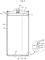
- FIG. 3 is a cross-sectional view an assembled state of FIG. 2 .
- an electric energy storage device includes a cell assembly 90, a cylindrical metal case 100 accommodating the cell assembly 90, a negative electrode external terminal 110 located at an upper portion of the metal case 100, a negative electrode internal terminal 111 disposed at an inner side of the negative electrode external terminal 110 and connected to a negative electrode of the cell assembly 90, a positive electrode external terminal 150 provided at one end of the metal case 100, a positive electrode internal terminal 140 disposed at an inner side of the positive electrode external terminal 150 and connected to a positive electrode of the cell assembly 90, and a terminal-fixing beading portion 101, 102 formed at the metal case 100 to provide a terminal fixing function.
- the cell assembly 90 includes a positive electrode, a negative electrode, a separator and an electrolyte to provide an electrochemical energy storage function.
- a normal jelly-roll cell may be employed as the cell assembly 90.
- the metal case 100 includes a cylindrical body having an inner space capable of accommodating the cell assembly 90 which is processed as a wound element and contained in a predetermined inner housing.
- the metal case 100 may be provided as an aluminum cylinder.
- a lower end portion closing the cylindrical body is formed at any one of the upper surface and the lower surface of the cylindrical body.
- the positive electrode external terminal 150 protruding outwardly is formed at a portion of the lower end portion.
- the negative electrode external terminal 110 caps the upper end of the metal case 100 and gives a current path.
- the negative electrode external terminal 110 has a circular outer circumferential surface corresponding to the inner circumferential surface of the metal case 100, and its upper and lower surfaces shape may be configured with various three-dimensional shapes.
- the edge of the negative electrode external terminal 110 is adjacent to the curling portion with an insulating member 130 being interposed therebetween.
- a thorough hole 113 extending in a thickness direction is formed at the center of the negative electrode external terminal 110.
- the thorough hole 113 is used, for example, as a space for installing an automatic reset safety valve 120 as well as a path for injecting an electrolyte and an air vent for vacuum operation.
- the negative electrode external terminal 110 is fixed to the metal case 100 by beading the metal case 100. Accordingly, the terminal-fixing beading portion 101 is formed at a side of the metal case 100 corresponding to the negative electrode external terminal 110.
- the negative electrode internal terminal 111 is disposed at a lower portion of the negative electrode external terminal 110 and connected to the negative electrode of the cell assembly 90.
- the positive electrode internal terminal 140 is fixed to the cell assembly 90 such that the upper surface of the terminal body 141 of the positive electrode internal terminal 140 and a part of the flange 145 come into contact with the cell assembly 90.
- the positive electrode internal terminal 140 is disposed inside the metal case 100 so that the lower surface thereof contacts the inner side of the lower end of the metal case 100, thereby contacting the positive electrode external terminal 150.
- the upper surface of the positive electrode internal terminal 140 is connected to the positive electrode of the cell assembly 90.
- the inner side of the lower end of the metal case 100 forms an inner bottom surface of the metal case 100.
- the positive electrode internal terminal 140 has a thin and flat plate-shaped terminal body 141, a flange 145 formed by extending an outer circumferential end of the terminal body 141 upwards, perpendicular to a plane of the terminal body 141, and a plurality of electrolyte impregnation holes 142 formed in the terminal body 141.
- the positive electrode internal terminal 140 is fixed to the metal case 100 by pressing the flange 145 by means of a terminal-fixing beading portion 102 protruding to the inside of the metal case 100.
- the terminal body 141 has a circular outer periphery, but is made of a thin plate-shaped body having no groove in the outer circumference thereof, unlike an existing internal terminal fixed to a metal case by a beading process.
- the terminal body 141 is disposed to make a surface contact with the inner side of the lower end of the metal case 100.
- the electrolyte impregnation holes 142 are formed to penetrate the terminal body 141 in the thickness direction so as to provide a passage for a liquid electrolyte during an electrolyte injection process.
- the plurality of electrolyte impregnation holes 142 may be mostly formed at regular intervals along the circumferential direction of the terminal body 141, and one of them may be formed at the center of the terminal body 141.
- the positive electrode internal terminal 140 is fixed in the metal case 100 by means of the terminal-fixing beading portion 102, which is formed at the lower side of the metal case 100 by a beading process, and the cell assembly 90.
- the positive electrode internal terminal 140 is fixed firmly in the metal case 100 since the flange 145 is pressed by the terminal-fixing beading portion 102 protruding into the metal case 100.
- the terminal-fixing beading portion 102 may be designed to have an upper edge 102b higher than the top end of the flange 145.
- the upper edge 102b and the lower edge 102c of the terminal-fixing beading portion 102 are positions where the terminal-fixing beading portion 102 begins to protrude from the inner surface of the metal case 100, which respectively correspond to the upper end and the lower end of the groove portion of the terminal-fixing beading portion 102.
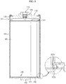
- FIG. 5 shows an electric energy storage device according to another embodiment of the present disclosure
- FIG. 6 shows a positive electrode internal terminal depicted in FIG. 5 in more detail
- the positive electrode internal terminal 140 is composed of a thin plate-shaped body having a circular outer periphery, and the positive electrode internal terminal 140 is disposed in a region A between a protruding end 102a of the terminal-fixing beading portion 102 and the inner side of the lower end of the metal case 100 serving as an internal terminal supporting surface and fixed by the terminal-fixing beading portion 102.
- the lower surface of the terminal body 141 of the positive electrode internal terminal 140 comes into contact with the inner side of the lower end of the metal case 100, and an upper surface edge 141a of the terminal body 141 is pressed by the terminal-fixing beading portion 102 and fixed inside the metal case 100.
- a lower surface edge 141b is provided at an opposite side of the upper surface edge 141a of the terminal body 141.
- the positive electrode internal terminal 140 may be disposed between the second edge 102c of the terminal-fixing beading portion 102 and the inner side of the lower end of the metal case 100.
- the positive electrode internal terminal 140 is disposed between the second edge 102c of the terminal-fixing beading portion 102 and the inner side of the lower end of the metal case 100, the positive electrode internal terminal 140 is designed to have a thickness t equal to the height between the second edge 102c of the terminal-fixing beading portion 102 and the inner side of the lower end of the metal case 100.
- the positive electrode internal terminal 140 has a thin design, and the flow in a vertical direction may be effectively prevented.
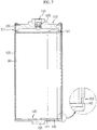
- FIG. 7 shows a modified example of the positive electrode internal terminal depicted in FIG. 5 .
- the upper surface edge of the positive electrode internal terminal 140 may chamfered at C1.8 or more or rounded at R1.5 or more to allow the positive electrode internal terminal 140 be seated at the inside of the metal case 100 and to improve the contact reliability.
- FIG. 8a shows an example in which the upper surface edge 141a of the positive electrode internal terminal 140 is chamfered.
- FIG. 8A if the upper surface edge 141a of the positive electrode internal terminal 140 is chamfered to form a first curved portion 143, during the beading process for fixing the positive electrode internal terminal 140 in the metal case 100, it is possible to prevent the inner surface of the metal case 100 from being damaged or broken by the upper surface edge 141a of the positive electrode internal terminal 140.
- the contact area between the positive electrode internal terminal 140 and the terminal-fixing beading portion 102 is widened, thereby securely fixing the positive electrode internal terminal 140 in the metal case 100.
- Fig. 8A shows an example in which the lower surface edge 141b of the positive electrode internal terminal 140 is chamfered.
- FIG. 8b if the lower surface edge 141b of the positive electrode internal terminal 140 is chamfered to form a second curved portion 144, it is possible to prevent that the positive electrode internal terminal 140 is pushed upwards by the inner edge where the side surface of the metal case 100 meets the inner side of the lower end thereof and thus causes contact inferiority with the bottom surface of the metal case 100.
- the upper surface edge 141a of the positive electrode internal terminal 140 may be chamfered and applied to an energy storage device, or as shown in FIG. 8b , the lower surface edge 141b of the positive electrode internal terminal 140 may be chamfered and applied to an energy storage device. Also, the positive electrode internal terminal 140 in which the upper surface edge 141a and the lower surface edge 141b are chamfered may also be applied to an energy storage device.
- the positive electrode internal terminal 140 in a state where the positive electrode internal terminal 140 is disposed at the inner side of the lower end of the metal case 100, the positive electrode internal terminal 140 may be conveniently fixed to the metal case 100 by performing a beading process at the outside of the metal case 100 in accordance with the height of the flange 145 of the positive electrode internal terminal 140 or the height of the terminal body 141.
- the positive electrode internal terminal 140 may be firmly fixed to the inner surface of the metal case 100 even though a beading groove is not separately formed at the outer circumference thereof.
- the positive electrode internal terminal 140 may be manufactured in a thin shape with a simple structure compared with the existing structure, and thus the inner space of the metal case 100 may be sufficiently secured. Accordingly, the internal pressure of the metal case 100 may be lowered, and thus the stability and life span of the electric energy storage device may be improved. In addition, the low resistance characteristic may be improved by bringing the positive electrode internal terminal 140 into close contact with the periphery of the terminal-fixing beading portion 102 with a wide contact area.
- the present disclosure is applied, it is possible to make a high capacitance storage device with a small and light design, and it is also possible to shorten the time required for the electrolyte impregnation process. Moreover, by sufficiently securing the inner space of the high capacitance storage device to lower the pressure resistance, it is possible to improve the stability and life span.
Landscapes
- Engineering & Computer Science (AREA)
- Power Engineering (AREA)
- Microelectronics & Electronic Packaging (AREA)
- Manufacturing & Machinery (AREA)
- Chemical & Material Sciences (AREA)
- Chemical Kinetics & Catalysis (AREA)
- Electrochemistry (AREA)
- General Chemical & Material Sciences (AREA)
- Connection Of Batteries Or Terminals (AREA)
- Electric Double-Layer Capacitors Or The Like (AREA)
- Sealing Battery Cases Or Jackets (AREA)
- Secondary Cells (AREA)
Priority Applications (1)
| Application Number | Priority Date | Filing Date | Title |
|---|---|---|---|
| PL16740336T PL3249668T3 (pl) | 2015-01-19 | 2016-01-08 | Urządzenie do magazynowania energii elektrycznej o ulepszonej konstrukcji instalacji wewnętrznego przyłącza |
Applications Claiming Priority (2)
| Application Number | Priority Date | Filing Date | Title |
|---|---|---|---|
| KR1020150008805A KR102143576B1 (ko) | 2015-01-19 | 2015-01-19 | 내부 터미널의 설치 구조가 개선된 전기에너지 저장장치 |
| PCT/KR2016/000182 WO2016117863A1 (ko) | 2015-01-19 | 2016-01-08 | 내부 터미널의 설치 구조가 개선된 전기에너지 저장장치 |
Publications (3)
| Publication Number | Publication Date |
|---|---|
| EP3249668A1 EP3249668A1 (en) | 2017-11-29 |
| EP3249668A4 EP3249668A4 (en) | 2018-04-04 |
| EP3249668B1 true EP3249668B1 (en) | 2021-08-11 |
Family
ID=56417340
Family Applications (1)
| Application Number | Title | Priority Date | Filing Date |
|---|---|---|---|
| EP16740336.9A Active EP3249668B1 (en) | 2015-01-19 | 2016-01-08 | Electric energy storage device having improved installation structure of internal terminal |
Country Status (8)
| Country | Link |
|---|---|
| US (1) | US10622165B2 (pl) |
| EP (1) | EP3249668B1 (pl) |
| JP (1) | JP6522765B2 (pl) |
| KR (1) | KR102143576B1 (pl) |
| CN (1) | CN107112148B (pl) |
| ES (1) | ES2895135T3 (pl) |
| PL (1) | PL3249668T3 (pl) |
| WO (1) | WO2016117863A1 (pl) |
Families Citing this family (9)
| Publication number | Priority date | Publication date | Assignee | Title |
|---|---|---|---|---|
| JPWO2017111137A1 (ja) | 2015-12-22 | 2018-10-18 | 味の素株式会社 | オリゴヌクレオチドの製造方法 |
| KR102547273B1 (ko) * | 2019-04-25 | 2023-06-23 | 엘에스머트리얼즈 주식회사 | 울트라 캐패시터 및 울트라 캐패시터 연결용 조립체 |
| CN110299249A (zh) * | 2019-06-11 | 2019-10-01 | 成都凹克新能源科技有限公司 | 一种电化学储能器件 |
| JP7561371B2 (ja) * | 2020-11-09 | 2024-10-04 | パナソニックIpマネジメント株式会社 | 電池 |
| US12132227B2 (en) | 2021-01-19 | 2024-10-29 | Lg Energy Solution, Ltd. | Battery, and battery pack and vehicle comprising the same |
| EP4325652A3 (en) | 2021-01-19 | 2024-02-28 | Lg Energy Solution, Ltd. | Battery, current collector for a battery, battery pack and vehicle including a battery pack |
| US12407028B2 (en) | 2021-02-19 | 2025-09-02 | Lg Energy Solution, Ltd. | Electrode assembly, battery, and battery pack and vehicle including the same |
| SE544360C2 (en) * | 2021-04-22 | 2022-04-19 | Northvolt Ab | Cylindrical secondary cell |
| DE102022128691A1 (de) * | 2022-10-28 | 2024-05-08 | Bayerische Motoren Werke Aktiengesellschaft | Elektrochemische Rundzelle, Fortbewegungsmittel und Verfahren zur Fertigung einer elektrochemischen Rundzelle |
Family Cites Families (16)
| Publication number | Priority date | Publication date | Assignee | Title |
|---|---|---|---|---|
| JP3210593B2 (ja) * | 1997-02-17 | 2001-09-17 | 日本碍子株式会社 | リチウム二次電池 |
| US6222720B1 (en) * | 1997-12-22 | 2001-04-24 | Asahi Glass Company Ltd. | Electric double layer capacitor |
| KR100560512B1 (ko) * | 2003-11-29 | 2006-03-16 | 삼성에스디아이 주식회사 | 이차전지 |
| CN2887989Y (zh) * | 2006-01-17 | 2007-04-11 | 王继海 | 一种伸缩式小型节能空调间 |
| JP2007258414A (ja) | 2006-03-23 | 2007-10-04 | Matsushita Electric Ind Co Ltd | 電気二重層コンデンサ |
| WO2007122894A1 (ja) * | 2006-03-23 | 2007-11-01 | Matsushita Electric Industrial Co., Ltd. | 電気二重層コンデンサとその製造方法 |
| CN101641754A (zh) * | 2007-03-30 | 2010-02-03 | 日本贵弥功株式会社 | 电解电容器 |
| US8390986B2 (en) * | 2010-03-24 | 2013-03-05 | Samhwa Capacitor Co., Ltd. | Super capacitor for high power |
| KR101142403B1 (ko) | 2010-09-13 | 2012-05-07 | 코칩 주식회사 | 전기이중층 커패시터 |
| US8773842B2 (en) * | 2011-03-11 | 2014-07-08 | Ls Mtron, Ltd. | Electrical energy storage device and manufacturing method thereof |
| KR101207372B1 (ko) * | 2011-03-11 | 2012-12-04 | 엘에스엠트론 주식회사 | 내압특성의 향상 구조를 갖는 전기에너지 저장장치 및 이를 위한 금속 케이스 |
| CN202887989U (zh) | 2012-09-27 | 2013-04-17 | 深圳市今朝时代新能源技术有限公司 | 一种焊接结构超级电容器 |
| KR101296224B1 (ko) * | 2012-10-10 | 2013-09-16 | 주식회사 쿨스 | 울트라 커패시터 |
| KR101537999B1 (ko) * | 2013-06-07 | 2015-07-20 | 주식회사 네스캡 | 전기 이중층 소자 |
| KR101345224B1 (ko) * | 2013-08-05 | 2013-12-26 | 주식회사 쿨스 | 울트라 커패시터 |
| CN103680999B (zh) * | 2014-01-10 | 2016-06-08 | 柯贝尔电能质量技术(上海)有限公司 | 一种超级电容器 |
-
2015
- 2015-01-19 KR KR1020150008805A patent/KR102143576B1/ko active Active
-
2016
- 2016-01-08 PL PL16740336T patent/PL3249668T3/pl unknown
- 2016-01-08 CN CN201680006147.9A patent/CN107112148B/zh active Active
- 2016-01-08 ES ES16740336T patent/ES2895135T3/es active Active
- 2016-01-08 US US15/544,313 patent/US10622165B2/en active Active
- 2016-01-08 WO PCT/KR2016/000182 patent/WO2016117863A1/ko not_active Ceased
- 2016-01-08 EP EP16740336.9A patent/EP3249668B1/en active Active
- 2016-01-08 JP JP2017537410A patent/JP6522765B2/ja active Active
Also Published As
| Publication number | Publication date |
|---|---|
| US10622165B2 (en) | 2020-04-14 |
| CN107112148B (zh) | 2019-04-16 |
| EP3249668A4 (en) | 2018-04-04 |
| JP6522765B2 (ja) | 2019-05-29 |
| PL3249668T3 (pl) | 2022-06-13 |
| EP3249668A1 (en) | 2017-11-29 |
| CN107112148A (zh) | 2017-08-29 |
| KR20160089178A (ko) | 2016-07-27 |
| ES2895135T3 (es) | 2022-02-17 |
| US20180247773A1 (en) | 2018-08-30 |
| WO2016117863A1 (ko) | 2016-07-28 |
| JP2018507544A (ja) | 2018-03-15 |
| KR102143576B1 (ko) | 2020-09-09 |
Similar Documents
| Publication | Publication Date | Title |
|---|---|---|
| EP3249668B1 (en) | Electric energy storage device having improved installation structure of internal terminal | |
| EP3246971B1 (en) | Electrical energy storage apparatus having improved coupling structure of internal terminal | |
| KR101166025B1 (ko) | 배터리 모듈 | |
| KR101217071B1 (ko) | 이차 전지 | |
| KR100922350B1 (ko) | 이차 전지 및 전지 모듈 | |
| KR101244735B1 (ko) | 이차 전지 | |
| KR20140124247A (ko) | 이차 전지 | |
| KR20150030548A (ko) | 이차전지 | |
| KR101181803B1 (ko) | 이차 전지 | |
| EP3246928B1 (en) | External terminal, having structure for preventing leakage of electrolyte, for electric energy storage device | |
| EP3246930B1 (en) | Electric energy storage device having improved terminal structure | |
| EP3509127B1 (en) | Secondary battery | |
| KR101568309B1 (ko) | 터미널 구조가 개선된 전기에너지 저장장치 및 이를 위한 터미널 구조 | |
| KR101803864B1 (ko) | 절연 소자 및 이를 포함하는 전기에너지 저장 장치 |
Legal Events
| Date | Code | Title | Description |
|---|---|---|---|
| STAA | Information on the status of an ep patent application or granted ep patent |
Free format text: STATUS: THE INTERNATIONAL PUBLICATION HAS BEEN MADE |
|
| PUAI | Public reference made under article 153(3) epc to a published international application that has entered the european phase |
Free format text: ORIGINAL CODE: 0009012 |
|
| STAA | Information on the status of an ep patent application or granted ep patent |
Free format text: STATUS: REQUEST FOR EXAMINATION WAS MADE |
|
| 17P | Request for examination filed |
Effective date: 20170816 |
|
| AK | Designated contracting states |
Kind code of ref document: A1 Designated state(s): AL AT BE BG CH CY CZ DE DK EE ES FI FR GB GR HR HU IE IS IT LI LT LU LV MC MK MT NL NO PL PT RO RS SE SI SK SM TR |
|
| AX | Request for extension of the european patent |
Extension state: BA ME |
|
| RIC1 | Information provided on ipc code assigned before grant |
Ipc: H01G 4/232 20060101ALN20180222BHEP Ipc: H01M 2/02 20060101ALI20180222BHEP Ipc: H01G 9/08 20060101ALI20180222BHEP Ipc: H01G 4/32 20060101ALN20180222BHEP Ipc: H01G 9/15 20060101ALI20180222BHEP Ipc: H01G 11/74 20130101AFI20180222BHEP Ipc: H01G 9/008 20060101ALI20180222BHEP Ipc: H01G 11/78 20130101ALI20180222BHEP Ipc: H01G 11/82 20130101ALI20180222BHEP |
|
| A4 | Supplementary search report drawn up and despatched |
Effective date: 20180302 |
|
| DAV | Request for validation of the european patent (deleted) | ||
| DAX | Request for extension of the european patent (deleted) | ||
| GRAP | Despatch of communication of intention to grant a patent |
Free format text: ORIGINAL CODE: EPIDOSNIGR1 |
|
| STAA | Information on the status of an ep patent application or granted ep patent |
Free format text: STATUS: GRANT OF PATENT IS INTENDED |
|
| RIC1 | Information provided on ipc code assigned before grant |
Ipc: H01G 4/32 20060101ALN20210331BHEP Ipc: H01G 4/232 20060101ALN20210331BHEP Ipc: H01G 11/82 20130101ALI20210331BHEP Ipc: H01G 9/15 20060101ALI20210331BHEP Ipc: H01M 50/107 20210101ALI20210331BHEP Ipc: H01G 9/08 20060101ALI20210331BHEP Ipc: H01G 9/008 20060101ALI20210331BHEP Ipc: H01G 11/78 20130101ALI20210331BHEP Ipc: H01G 11/74 20130101AFI20210331BHEP |
|
| INTG | Intention to grant announced |
Effective date: 20210421 |
|
| GRAS | Grant fee paid |
Free format text: ORIGINAL CODE: EPIDOSNIGR3 |
|
| GRAA | (expected) grant |
Free format text: ORIGINAL CODE: 0009210 |
|
| STAA | Information on the status of an ep patent application or granted ep patent |
Free format text: STATUS: THE PATENT HAS BEEN GRANTED |
|
| AK | Designated contracting states |
Kind code of ref document: B1 Designated state(s): AL AT BE BG CH CY CZ DE DK EE ES FI FR GB GR HR HU IE IS IT LI LT LU LV MC MK MT NL NO PL PT RO RS SE SI SK SM TR |
|
| REG | Reference to a national code |
Ref country code: CH Ref legal event code: EP |
|
| REG | Reference to a national code |
Ref country code: DE Ref legal event code: R096 Ref document number: 602016062003 Country of ref document: DE |
|
| REG | Reference to a national code |
Ref country code: IE Ref legal event code: FG4D Ref country code: AT Ref legal event code: REF Ref document number: 1420241 Country of ref document: AT Kind code of ref document: T Effective date: 20210915 |
|
| REG | Reference to a national code |
Ref country code: DE Ref legal event code: R081 Ref document number: 602016062003 Country of ref document: DE Owner name: LS MATERIALS LTD., KR Free format text: FORMER OWNER: LS MTRON LTD., ANYANG-SI, GYEONGGI-DO, KR |
|
| REG | Reference to a national code |
Ref country code: CH Ref legal event code: PK Free format text: BERICHTIGUNGEN |
|
| RAP2 | Party data changed (patent owner data changed or rights of a patent transferred) |
Owner name: LS MATERIALS LTD. |
|
| REG | Reference to a national code |
Ref country code: LT Ref legal event code: MG9D |
|
| REG | Reference to a national code |
Ref country code: NL Ref legal event code: MP Effective date: 20210811 |
|
| REG | Reference to a national code |
Ref country code: AT Ref legal event code: MK05 Ref document number: 1420241 Country of ref document: AT Kind code of ref document: T Effective date: 20210811 |
|
| PG25 | Lapsed in a contracting state [announced via postgrant information from national office to epo] |
Ref country code: NO Free format text: LAPSE BECAUSE OF FAILURE TO SUBMIT A TRANSLATION OF THE DESCRIPTION OR TO PAY THE FEE WITHIN THE PRESCRIBED TIME-LIMIT Effective date: 20211111 Ref country code: PT Free format text: LAPSE BECAUSE OF FAILURE TO SUBMIT A TRANSLATION OF THE DESCRIPTION OR TO PAY THE FEE WITHIN THE PRESCRIBED TIME-LIMIT Effective date: 20211213 Ref country code: HR Free format text: LAPSE BECAUSE OF FAILURE TO SUBMIT A TRANSLATION OF THE DESCRIPTION OR TO PAY THE FEE WITHIN THE PRESCRIBED TIME-LIMIT Effective date: 20210811 Ref country code: FI Free format text: LAPSE BECAUSE OF FAILURE TO SUBMIT A TRANSLATION OF THE DESCRIPTION OR TO PAY THE FEE WITHIN THE PRESCRIBED TIME-LIMIT Effective date: 20210811 Ref country code: AT Free format text: LAPSE BECAUSE OF FAILURE TO SUBMIT A TRANSLATION OF THE DESCRIPTION OR TO PAY THE FEE WITHIN THE PRESCRIBED TIME-LIMIT Effective date: 20210811 Ref country code: BG Free format text: LAPSE BECAUSE OF FAILURE TO SUBMIT A TRANSLATION OF THE DESCRIPTION OR TO PAY THE FEE WITHIN THE PRESCRIBED TIME-LIMIT Effective date: 20211111 Ref country code: LT Free format text: LAPSE BECAUSE OF FAILURE TO SUBMIT A TRANSLATION OF THE DESCRIPTION OR TO PAY THE FEE WITHIN THE PRESCRIBED TIME-LIMIT Effective date: 20210811 Ref country code: SE Free format text: LAPSE BECAUSE OF FAILURE TO SUBMIT A TRANSLATION OF THE DESCRIPTION OR TO PAY THE FEE WITHIN THE PRESCRIBED TIME-LIMIT Effective date: 20210811 Ref country code: RS Free format text: LAPSE BECAUSE OF FAILURE TO SUBMIT A TRANSLATION OF THE DESCRIPTION OR TO PAY THE FEE WITHIN THE PRESCRIBED TIME-LIMIT Effective date: 20210811 |
|
| REG | Reference to a national code |
Ref country code: ES Ref legal event code: FG2A Ref document number: 2895135 Country of ref document: ES Kind code of ref document: T3 Effective date: 20220217 |
|
| PG25 | Lapsed in a contracting state [announced via postgrant information from national office to epo] |
Ref country code: LV Free format text: LAPSE BECAUSE OF FAILURE TO SUBMIT A TRANSLATION OF THE DESCRIPTION OR TO PAY THE FEE WITHIN THE PRESCRIBED TIME-LIMIT Effective date: 20210811 Ref country code: GR Free format text: LAPSE BECAUSE OF FAILURE TO SUBMIT A TRANSLATION OF THE DESCRIPTION OR TO PAY THE FEE WITHIN THE PRESCRIBED TIME-LIMIT Effective date: 20211112 |
|
| PG25 | Lapsed in a contracting state [announced via postgrant information from national office to epo] |
Ref country code: NL Free format text: LAPSE BECAUSE OF FAILURE TO SUBMIT A TRANSLATION OF THE DESCRIPTION OR TO PAY THE FEE WITHIN THE PRESCRIBED TIME-LIMIT Effective date: 20210811 |
|
| PG25 | Lapsed in a contracting state [announced via postgrant information from national office to epo] |
Ref country code: DK Free format text: LAPSE BECAUSE OF FAILURE TO SUBMIT A TRANSLATION OF THE DESCRIPTION OR TO PAY THE FEE WITHIN THE PRESCRIBED TIME-LIMIT Effective date: 20210811 |
|
| REG | Reference to a national code |
Ref country code: DE Ref legal event code: R097 Ref document number: 602016062003 Country of ref document: DE |
|
| PG25 | Lapsed in a contracting state [announced via postgrant information from national office to epo] |
Ref country code: SM Free format text: LAPSE BECAUSE OF FAILURE TO SUBMIT A TRANSLATION OF THE DESCRIPTION OR TO PAY THE FEE WITHIN THE PRESCRIBED TIME-LIMIT Effective date: 20210811 Ref country code: SK Free format text: LAPSE BECAUSE OF FAILURE TO SUBMIT A TRANSLATION OF THE DESCRIPTION OR TO PAY THE FEE WITHIN THE PRESCRIBED TIME-LIMIT Effective date: 20210811 Ref country code: RO Free format text: LAPSE BECAUSE OF FAILURE TO SUBMIT A TRANSLATION OF THE DESCRIPTION OR TO PAY THE FEE WITHIN THE PRESCRIBED TIME-LIMIT Effective date: 20210811 Ref country code: EE Free format text: LAPSE BECAUSE OF FAILURE TO SUBMIT A TRANSLATION OF THE DESCRIPTION OR TO PAY THE FEE WITHIN THE PRESCRIBED TIME-LIMIT Effective date: 20210811 Ref country code: CZ Free format text: LAPSE BECAUSE OF FAILURE TO SUBMIT A TRANSLATION OF THE DESCRIPTION OR TO PAY THE FEE WITHIN THE PRESCRIBED TIME-LIMIT Effective date: 20210811 Ref country code: AL Free format text: LAPSE BECAUSE OF FAILURE TO SUBMIT A TRANSLATION OF THE DESCRIPTION OR TO PAY THE FEE WITHIN THE PRESCRIBED TIME-LIMIT Effective date: 20210811 |
|
| PLBE | No opposition filed within time limit |
Free format text: ORIGINAL CODE: 0009261 |
|
| STAA | Information on the status of an ep patent application or granted ep patent |
Free format text: STATUS: NO OPPOSITION FILED WITHIN TIME LIMIT |
|
| 26N | No opposition filed |
Effective date: 20220512 |
|
| PG25 | Lapsed in a contracting state [announced via postgrant information from national office to epo] |
Ref country code: SI Free format text: LAPSE BECAUSE OF FAILURE TO SUBMIT A TRANSLATION OF THE DESCRIPTION OR TO PAY THE FEE WITHIN THE PRESCRIBED TIME-LIMIT Effective date: 20210811 Ref country code: MC Free format text: LAPSE BECAUSE OF FAILURE TO SUBMIT A TRANSLATION OF THE DESCRIPTION OR TO PAY THE FEE WITHIN THE PRESCRIBED TIME-LIMIT Effective date: 20210811 |
|
| GBPC | Gb: european patent ceased through non-payment of renewal fee |
Effective date: 20220108 |
|
| REG | Reference to a national code |
Ref country code: BE Ref legal event code: MM Effective date: 20220131 |
|
| PG25 | Lapsed in a contracting state [announced via postgrant information from national office to epo] |
Ref country code: LU Free format text: LAPSE BECAUSE OF NON-PAYMENT OF DUE FEES Effective date: 20220108 Ref country code: GB Free format text: LAPSE BECAUSE OF NON-PAYMENT OF DUE FEES Effective date: 20220108 |
|
| PG25 | Lapsed in a contracting state [announced via postgrant information from national office to epo] |
Ref country code: FR Free format text: LAPSE BECAUSE OF NON-PAYMENT OF DUE FEES Effective date: 20220131 Ref country code: BE Free format text: LAPSE BECAUSE OF NON-PAYMENT OF DUE FEES Effective date: 20220131 |
|
| PG25 | Lapsed in a contracting state [announced via postgrant information from national office to epo] |
Ref country code: IE Free format text: LAPSE BECAUSE OF NON-PAYMENT OF DUE FEES Effective date: 20220108 |
|
| P01 | Opt-out of the competence of the unified patent court (upc) registered |
Effective date: 20230530 |
|
| PG25 | Lapsed in a contracting state [announced via postgrant information from national office to epo] |
Ref country code: HU Free format text: LAPSE BECAUSE OF FAILURE TO SUBMIT A TRANSLATION OF THE DESCRIPTION OR TO PAY THE FEE WITHIN THE PRESCRIBED TIME-LIMIT; INVALID AB INITIO Effective date: 20160108 |
|
| PG25 | Lapsed in a contracting state [announced via postgrant information from national office to epo] |
Ref country code: MK Free format text: LAPSE BECAUSE OF FAILURE TO SUBMIT A TRANSLATION OF THE DESCRIPTION OR TO PAY THE FEE WITHIN THE PRESCRIBED TIME-LIMIT Effective date: 20210811 Ref country code: CY Free format text: LAPSE BECAUSE OF FAILURE TO SUBMIT A TRANSLATION OF THE DESCRIPTION OR TO PAY THE FEE WITHIN THE PRESCRIBED TIME-LIMIT Effective date: 20210811 |
|
| PG25 | Lapsed in a contracting state [announced via postgrant information from national office to epo] |
Ref country code: MT Free format text: LAPSE BECAUSE OF FAILURE TO SUBMIT A TRANSLATION OF THE DESCRIPTION OR TO PAY THE FEE WITHIN THE PRESCRIBED TIME-LIMIT Effective date: 20210811 |
|
| PGFP | Annual fee paid to national office [announced via postgrant information from national office to epo] |
Ref country code: DE Payment date: 20241223 Year of fee payment: 10 |
|
| PGFP | Annual fee paid to national office [announced via postgrant information from national office to epo] |
Ref country code: ES Payment date: 20250207 Year of fee payment: 10 |
|
| PGFP | Annual fee paid to national office [announced via postgrant information from national office to epo] |
Ref country code: CH Payment date: 20250201 Year of fee payment: 10 |
|
| PGFP | Annual fee paid to national office [announced via postgrant information from national office to epo] |
Ref country code: IT Payment date: 20241224 Year of fee payment: 10 |
|
| PG25 | Lapsed in a contracting state [announced via postgrant information from national office to epo] |
Ref country code: TR Free format text: LAPSE BECAUSE OF FAILURE TO SUBMIT A TRANSLATION OF THE DESCRIPTION OR TO PAY THE FEE WITHIN THE PRESCRIBED TIME-LIMIT Effective date: 20210811 |
|
| PGFP | Annual fee paid to national office [announced via postgrant information from national office to epo] |
Ref country code: PL Payment date: 20251222 Year of fee payment: 11 |
|
| REG | Reference to a national code |
Ref country code: CH Ref legal event code: U11 Free format text: ST27 STATUS EVENT CODE: U-0-0-U10-U11 (AS PROVIDED BY THE NATIONAL OFFICE) Effective date: 20260201 |