EP3249302B1 - Domestic cooking device - Google Patents
Domestic cooking device Download PDFInfo
- Publication number
- EP3249302B1 EP3249302B1 EP17170859.7A EP17170859A EP3249302B1 EP 3249302 B1 EP3249302 B1 EP 3249302B1 EP 17170859 A EP17170859 A EP 17170859A EP 3249302 B1 EP3249302 B1 EP 3249302B1
- Authority
- EP
- European Patent Office
- Prior art keywords
- temperature
- circuit
- heating
- cooking appliance
- relay
- Prior art date
- Legal status (The legal status is an assumption and is not a legal conclusion. Google has not performed a legal analysis and makes no representation as to the accuracy of the status listed.)
- Active
Links
- 238000010411 cooking Methods 0.000 title claims description 108
- 238000010438 heat treatment Methods 0.000 claims description 80
- 238000001816 cooling Methods 0.000 claims description 19
- 238000000034 method Methods 0.000 claims description 8
- 230000001419 dependent effect Effects 0.000 claims description 7
- 230000001105 regulatory effect Effects 0.000 claims description 7
- 230000003466 anti-cipated effect Effects 0.000 claims 1
- 239000000523 sample Substances 0.000 claims 1
- 239000004020 conductor Substances 0.000 description 16
- 244000037459 secondary consumers Species 0.000 description 13
- 230000007935 neutral effect Effects 0.000 description 11
- 230000008901 benefit Effects 0.000 description 6
- 238000009529 body temperature measurement Methods 0.000 description 6
- 238000011161 development Methods 0.000 description 6
- 230000009467 reduction Effects 0.000 description 5
- 230000001276 controlling effect Effects 0.000 description 3
- 238000001514 detection method Methods 0.000 description 3
- BASFCYQUMIYNBI-UHFFFAOYSA-N platinum Chemical compound [Pt] BASFCYQUMIYNBI-UHFFFAOYSA-N 0.000 description 3
- 230000004913 activation Effects 0.000 description 2
- 230000000694 effects Effects 0.000 description 2
- 238000005265 energy consumption Methods 0.000 description 2
- 238000011156 evaluation Methods 0.000 description 2
- 238000013021 overheating Methods 0.000 description 2
- 238000012545 processing Methods 0.000 description 2
- 230000003213 activating effect Effects 0.000 description 1
- 238000010276 construction Methods 0.000 description 1
- 238000013100 final test Methods 0.000 description 1
- 229910052697 platinum Inorganic materials 0.000 description 1
- 230000008569 process Effects 0.000 description 1
- 230000003134 recirculating effect Effects 0.000 description 1
- 238000012360 testing method Methods 0.000 description 1
Images
Classifications
-
- H—ELECTRICITY
- H05—ELECTRIC TECHNIQUES NOT OTHERWISE PROVIDED FOR
- H05B—ELECTRIC HEATING; ELECTRIC LIGHT SOURCES NOT OTHERWISE PROVIDED FOR; CIRCUIT ARRANGEMENTS FOR ELECTRIC LIGHT SOURCES, IN GENERAL
- H05B1/00—Details of electric heating devices
- H05B1/02—Automatic switching arrangements specially adapted to apparatus ; Control of heating devices
- H05B1/0227—Applications
- H05B1/0252—Domestic applications
- H05B1/0258—For cooking
- H05B1/0261—For cooking of food
- H05B1/0263—Ovens
-
- F—MECHANICAL ENGINEERING; LIGHTING; HEATING; WEAPONS; BLASTING
- F24—HEATING; RANGES; VENTILATING
- F24C—DOMESTIC STOVES OR RANGES ; DETAILS OF DOMESTIC STOVES OR RANGES, OF GENERAL APPLICATION
- F24C7/00—Stoves or ranges heated by electric energy
- F24C7/08—Arrangement or mounting of control or safety devices
- F24C7/082—Arrangement or mounting of control or safety devices on ranges, e.g. control panels, illumination
- F24C7/085—Arrangement or mounting of control or safety devices on ranges, e.g. control panels, illumination on baking ovens
-
- F—MECHANICAL ENGINEERING; LIGHTING; HEATING; WEAPONS; BLASTING
- F24—HEATING; RANGES; VENTILATING
- F24C—DOMESTIC STOVES OR RANGES ; DETAILS OF DOMESTIC STOVES OR RANGES, OF GENERAL APPLICATION
- F24C7/00—Stoves or ranges heated by electric energy
- F24C7/08—Arrangement or mounting of control or safety devices
- F24C7/087—Arrangement or mounting of control or safety devices of electric circuits regulating heat
Definitions
- the invention relates to a household cooking appliance, comprising a plurality of electrically operable heating elements for heating a cooking space, a mechanically switching operating mode selector switch for switching on at least one heating element depending on its switching position, a mechanical temperature controller for regulating the connected heating element depending on a temperature of the cooking space, which temperature controller is electrically connected in series with the radiators, and an electronic circuit.
- the invention is particularly advantageously applicable to ovens, in particular ovens.
- DE 10 2011 017 638 A1 relates to a method for operating a cooking device, in which at least one heating unit of the cooking device is operated at least temporarily by a controller unit of the cooking device, the controller unit being activated and the heating unit being operated by the controller unit during a running cooking program in a first time interval, and in a second time interval the controller unit is deactivated and a clocked operation of the heating unit is controlled by a timer of the cooking device.
- EP 2 063 180 A2 discloses a heating cycle for a cooking chamber of a cooking appliance, comprising the following steps: activating at least one heating element for heating the cooking chamber until a predetermined limit temperature is reached; subsequently switching down a heating power of the at least one radiator to allow the cooking space to cool below the predetermined limit temperature; and subsequently clocked activation of at least one radiator with a predetermined clocking property for a predetermined clocking time interval for heating the cooking space until the predetermined limit temperature is reached.
- EP 1 461 568 B1 discloses a method for controlling energy consumption in an oven which is filled with food when it is cold and is then heated to its operating temperature at full power during a warm-up period and during a subsequent period at which the operating temperature is kept heated by supplying full power at a certain repetition rate.
- An electrical circuit used to carry out the method has a thermostat which is connected in series with the heating elements, and a timer switching device which is designed to deliver the desired duty cycle and the desired repetition rate, and the effect of the thermostat during the subsequent heating period.
- the timer switching device can be an energy control device which is connected between the thermostat switch and the electrical elements in parallel with a first temperature switch, which is normally open and closes at a temperature of approximately 130 ° C., and in parallel with a second temperature switch, which is normally is closed and opens at a temperature of approx. 65 ° C.
- DE 10313 596 A1 discloses an oven device with a mechanical temperature controller and an electronic clock. Presentation images for displaying various operating modes are integrated in a display panel of the electronic watch and can be controlled by the electronic control device of the watch depending on the respectively set operating mode, for displaying when the relevant operating mode is switched on.
- EP 2 518 410 A2 discloses a method for operating a cooking device, in which the operation of at least one heating unit of the cooking device is carried out at least temporarily by a first electronic unit of the cooking device, the first electronic unit being activated in a first time interval during an ongoing cooking program and the operation of the heating unit by the first electronic unit takes place, and in a second time interval the first electronic unit is deactivated and a clocked operation of the heating unit is carried out by a second electronic unit of the cooking device
- a household cooking appliance comprising a plurality of electrically operable radiators for heating a cooking space, a mechanically switching operating mode selector switch for switching on at least one radiator depending on a switching position selected or set by the user, and a mechanical temperature controller for regulating the connected radiators depending on a temperature of the cooking space, which mechanical temperature controller is electrically connected in series with the radiators, and an electronic circuit, a first relay (hereinafter referred to as "heating circuit relay" without restricting generality) electrically connected in series with the radiators and the mechanical temperature controller is and can be switched by means of the electronic circuit, the electronic circuit is connected to the operating selector switch in order to recognize a switching position set by the operating selector switch and the electr Onical circuit is set up to switch the heating circuit relay on and off as a function of the detected switching position of the operating selector switch with a predetermined switching pattern during operation.
- a first relay hereinafter referred to as "heating circuit relay” without restricting generality
- This household cooking appliance has the advantage that it can work like a purely mechanically controlled cooking appliance, with or as long as the heating circuit relay is permanently closed during operation, which enables a particularly inexpensive construction.
- the household cooking appliance is able to operate the radiators during operation by means of a particularly simple and inexpensive electronic unit via a corresponding control of the heating circuit relay.
- the electronic unit can be kept simple, since basic functionalities such as temperature setting, temperature measurement and regulation are already covered by the very inexpensive mechanical temperature controller.
- Such a household cooking appliance is only slightly more expensive than a purely mechanically controlled cooking appliance which has an electronic clock for a clock display or for the provision of time-controlled operation (i.e., time-limited or time-shifted operation), but is considerably cheaper than a purely electronically controlled cooking appliance ,
- An operating mode in which the heating circuit relay is switched during operation can also be referred to as a special operating mode.
- a special function can be, for example, the "temperature reduction" function.
- a cooking space temperature is adjusted to a predetermined setpoint by means of the mechanical temperature controller. If the setpoint is, for example, above a predetermined threshold value, the radiators are switched, in particular clocking, after a, possibly temperature-dependent, period of time in order to lower the cooking space temperature, for example by 30 ° C. In this way, for example, a temperature of a viewing window of a cooking space door can be kept below a desired value, which increases user safety.
- a cooking result is not or only slightly changed by the temperature reduction. Possibly. may extend the cooking time.
- An operating mode that has the special function "temperature reduction” can itself be a special operating mode ("safety cooking”).
- This special operating mode can be regarded as a “hybrid” operating mode if it has conventional operating sections which regulate the temperature by means of the temperature controller and which operate by switching, in particular clocking, using the radiator relay.
- Another possible special operating mode can be the energy-saving mode (so-called “energy-saving mode”), in which a predetermined amount of heat is introduced into the cooking space per unit of time. This can be done by clocked operation of the radiators used with a predetermined duty cycle. The cooking chamber temperature is not regulated here.
- Another special mode of operation can be low-temperature cooking or a simple automatic roasting.
- the heating circuit relay can also be switched to implement time-limited operation or time-shifted operation, but this is not considered a special functionality. In particular, such a switching of the radiators may not be considered as being in operation.
- the fact that the electronic circuit is set up to switch the heating circuit relay as a function of the detected switching position and thus the operating mode means that the heating circuit relay is switched on and off during operation.
- This includes switching with a predetermined switching pattern or switching rule.
- the switching on and off can include clocked switching, e.g. with a predefined duty cycle, a predefined pulse duration etc.
- the household cooking appliance has at least one cooking space.
- the household cooking appliance has at least one oven functionality, possibly also a steam addition functionality, in particular a steam cooking functionality.
- the household cooking device can be an independent cooking device or a cooking device / hob combination or stove.
- the radiators can have, for example, at least one top heat or grill radiator, a bottom heat radiator and / or a ring or circulating air radiator. These radiators can be resistance radiators.
- the mechanically switching mode selector switch is set up to open or close at least one associated electrical contact as a function of the selected or actuated switching position and thus the operating mode by means of manual actuation. In particular, by opening or closing the at least one contact, at least one heating element can be switched on for operation under the set operating mode.
- the operating selector switch can be used for different switching positions or operating modes switch on different radiators or combinations of radiators.
- the operating selector switch can also be referred to as a preselection switch.
- the mechanical temperature controller is set up to regulate the cooking space temperature as a function of a target temperature set there by a user. This is done without electronic regulatory contributions, but mechanically or electromechanically, e.g. using a capillary tube regulator.
- a mechanical temperature controller is very inexpensive and robust.
- the mechanical temperature controller can also be referred to as an electromechanical temperature controller, mechanical thermoregulator or thermostat.
- the mechanical temperature controller can be, for example, a capillary tube controller, a bimetal switch, etc.
- the mechanical temperature controller is electrically connected in series with the radiators, so that current can flow through the radiators through the mechanical temperature controller. If the temperature at the mechanical temperature controller is above the set target temperature, an electrical contact of the mechanical temperature controller is open and no current flows through the radiators. If the temperature at the mechanical temperature controller is below the set target temperature, the electrical contact of the temperature controller is closed and current can flow through the (switched on) radiators.
- the electronic circuit can be a simple electronic circuit with an integrated circuit - for example a controller - which can control or switch the heating circuit relay.
- the heating circuit relay can be a component of the electronic circuit.
- the electronic circuit can switch the heating circuit relay clocking, ie in particular with a predetermined duty cycle and a predetermined period.
- the electronic circuit can also keep the heating circuit relay closed for at least one specific operating mode.
- the electronic circuit can switch and in particular have at least one relay for switching at least one consumer (in particular a radiator and / or secondary consumer), which enables a particularly compact circuit.
- the heating circuit relay can be an electrically controlled, mechanically switching relay.
- the heating circuit relay can alternatively be an electronically controlled switching element such as a triac or similar. his.
- a heating circuit relay can therefore generally be understood to mean an electrically or electronically controlled switching element.
- the heating circuit relay is electrically connected in series with the (connected) radiators and the electrical contact of the mechanical temperature controller, which enables particularly simple switching.
- the electronic circuit is set up to switch the heating circuit relay for at least one special operating mode (e.g. for an energy-saving operating mode) during operation and to switch at least one other, conventional operating mode to close or to keep it permanently closed.
- a satisfactory cooking result is not achieved with mechanical temperature controllers at low temperatures, since the mechanical temperature controllers then have too high an inertia.
- the mechanical temperature controller for high temperatures can be used as before in mechanically controlled ovens for temperature control, in particular also in conventional operating modes such as a grill mode, a circulating air or hot air mode, an upper and / or lower heat mode, etc.
- clocked low-temperature operation of the radiators gives better cooking results. The clocked operation may only be controlled.
- the mechanical temperature controller is then preferably set so that it remains closed during the operating sequence of the low-temperature operating mode. It can then be used as additional protection against overheating.
- a low temperature mode can e.g. soft cooking (also known as low temperature cooking) or energy saving mode.
- the electronic circuit is an electronic clock circuit ("electronic clock") for the time-limited and / or time-delayed operation of the at least one radiator.
- electronic clock is available inexpensively and in particular requires only a few electronic components, for example a microcontroller.
- the clock circuit can in particular have a microcontroller, the heating circuit relay for controlling a current flow at least through the radiators and a processing of an input signal coming from the operating selector switch.
- electronic clock circuit can now also be used to control or regulate consumers (in particular radiators) during operation.
- the heating circuit relay can be switched on and off for time-controlled, time-limited or time-shifted operation.
- the relay that is used in conventional clock circuits for time-controlled (i.e., time-limited or time-shifted) operation of the radiators can now also be used to switch the radiators on and off during operation.
- conventional clock circuits only need to be modified slightly, possibly only by adapting their software or firmware.
- the mode selector switch is a rotary selector switch that has a coding switch circuit board, the output of which is connected to an input of the electronic circuit.
- the rotary selector switch can have simple switched contacts instead of a coding switch board.
- the electronic circuit has a main relay which is connected in series with the radiators and with auxiliary consumers of the household cooking appliance.
- a particularly large number, in particular all, of consumers can be switched off together by means of only one relay.
- Auxiliary consumers can include, for example, an oven light (e.g. an oven lamp), a forced-air motor, an oven operating indicator lamp and / or a cooling fan motor.
- an oven light e.g. an oven lamp
- a forced-air motor e.g. an oven lamp
- an oven operating indicator lamp e.g. an oven operating indicator lamp
- a cooling fan motor e.g. an oven fan motor
- the electronic circuit can switch a further relay (“secondary consumer relay”), which is connected in series with at least one secondary consumer of the household cooking appliance and independently, for example in parallel, to the radiators.
- a radiator output is not switched in particular via the auxiliary consumer relay.
- the secondary consumer relay can be implemented inexpensively, since only small currents are switched.
- the at least one Ancillary consumers can also be switched independently of the radiators. This enables a more flexible option for independent - for example, time-shifted - operation of radiators and auxiliary consumers.
- the radiators can be switched off by means of a common relay (namely the heating circuit relay), which enables a particularly high level of safety while the at least one secondary consumer can still be operated.
- the electronic circuit can have the secondary consumer relay or the secondary consumer relay can be a component of the electronic clock circuit, which enables a particularly compact circuit.
- At least one cooling fan motor in series with the auxiliary consumer relay and in particular independently, e.g. parallel to the other consumers.
- the cooling fan motor can be switched (e.g. switched on or off) independently of the radiators (and possibly also to other secondary consumers), in particular temperature or time-controlled, by means of the electronic circuit.
- the control of a fan run-on via a temperature limiter e.g. a Klixon
- the oven lighting, the circulating air motor and the oven operating indicator lamp are each connected in series with the operating selector switch, in particular in such a way that when the operating selector switch is in the off position, the Circuits of these consumers are interrupted. It can thereby be achieved that only the cooling fan motor can also be operated in an off position of the operating selector switch.
- At least one cooling fan motor can be switched independently of the other consumers depending on the position of the rotary selector and can be arranged in series with the main relay in this position of the rotary selector. At least one cooling fan motor can also be switched independently of the other consumers as a function of the position of the rotary selector and can be arranged in series with the secondary consumer relay in this position of the rotary selector.
- the electronic circuit is connected to a temperature sensor or temperature sensor for measuring a cooking space temperature.
- a temperature sensor or temperature sensor for measuring a cooking space temperature.
- control and / or regulation functions brought about by the electronic circuit can take place as a function of the cooking space temperature.
- the electronic parameters e.g. the cycle ratio
- the electronic circuit can regulate the cooking space temperature by switching the heating circuit relay or control it depending on the temperature.
- the mechanical temperature controller that is still present can be used in particular to ensure operational safety, in particular against overheating. For example, it can also be avoided that the electronic circuit must meet increased safety requirements, which would make it considerably more expensive.
- a run-on of a cooling fan e.g. its duration or "run-on period" and / or its speed can be controlled as a function of the cooking space temperature, for example by a temperature-dependent switching of the auxiliary consumer relay.
- This has the advantage that the run-on time is not unnecessarily long, but sufficient cooling and dewatering of the cooking space can be achieved. This reduces energy consumption and noise pollution during fan run-on.
- a temperature-based door opening detection is integrated in the electronic circuit, for example to ensure subsequent operation (i.e. operation after a preset cooking time has expired) without disadvantages for the cooking result.
- This can be implemented with the aid of the electronic temperature measurement and a correspondingly implemented algorithm for evaluating the temperature profile of the cooking device.
- the oven temperature can be controlled and / or regulated differently after detection of a drop in the cooking space temperature in order to compensate for the influence of this drop in temperature.
- the clocked operation can be interrupted for the required compensation period.
- the drop in temperature can e.g. be caused by opening a cooking chamber door.
- the cooking space temperature can be reduced on the device side depending on the electronically measured cooking space temperature, in particular can be controlled or regulated as a function of time and / or temperature.
- This can include, for example, that a cooking space temperature set by the user using the thermostat (e.g. of 270 ° C) is automatically lowered (e.g. to 230 ° C) after a predetermined period of time in order to limit a front temperature on the cooking space door.
- This lowering of the cooking space temperature can e.g. can be achieved by opening the heating circuit relay for a correspondingly long time and / or frequently.
- the temperature sensor is preferably on the holder of the sensor of the temperature controller (preferably capillary tube controller) with which it is attached to or in the oven. attached, because there are identical temperature values relative to a cooking space center temperature in different operating modes.
- the temperature controller preferably capillary tube controller
- the object is also achieved by a method for operating the household cooking appliance as described above, wherein when an operating mode is selected in which at least one radiator is operated in a clocked manner, the mechanical temperature controller is set to a temperature which is higher than one maximum cooking space temperature to be expected, in particular to a maximum adjustable temperature. In this way, it can be prevented particularly safely and with simple means that the mechanical temperature controller intervenes in the operation of at least one consumer during switching, in particular clocked operation, since the mechanical temperature controller then remains closed, as expected.
- the task is also solved by methods which correspond to the special functions and / or special operating modes listed above, e.g. Temperature reduction, energy saving mode, etc.
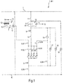
- Fig.1 shows a first circuit 1 for operating a household appliance in the form of a first oven B1 under several operating modes.
- the oven B1 has several radiators, namely here, for example, a first top heat or grill heater 2, a second top heat or grill heater 3, a bottom heat radiator 4 and a circulating air or ring heater 5.
- the heaters 2 to 5 are electrically connected to an outer conductor L. (eg operated with an AC voltage of 230 V) and connected to a neutral conductor N.
- the radiators 2 to 5 are arranged here, for example, electrically parallel to one another.
- a temperature limiter 6 is connected between the radiators 2 to 5 on the one hand and the neutral conductor N on the other hand. Furthermore, between the outer conductor L and the radiators 2 to 5 in series: a main relay 7, a mechanical rotary selector switch 8, a mechanical temperature controller - here e.g. formed as a user-adjustable capillary tube controller 9 - and a heating circuit relay 10 switched.
- the main relay 7 and the heating circuit relay 10 are components of a clock circuit 11.
- the clock circuit 11 is constructed as an electronic circuit and, in addition to the relays 7 and 10, can have at least one integrated circuit (e.g. a microcontroller, not shown) etc.
- the clock circuit 11 is used, among other things, to control the time of the oven B1 (e.g. to implement a timer function and to display the time) and can also have a display device 12 (e.g. a 7-segment display).
- the clock circuit 11 is connected here directly between the outer conductor L and the neutral conductor N.
- the clock circuit 11 is also set up so that it can switch the heating circuit relay 10 and / or the main relay 7.
- an input 13 of the clock circuit 11 is connected to an output 14 of the rotary selector switch 8.
- the rotary selector switch 8 is equipped with a coding device 15 (e.g. in the form of a coding switch circuit board, e.g. based on bit coding by means of, for example, a gray code), which assigns an output signal or a unique electrical interface configuration to each rotary position of the rotary selector switch 8. Therefore, the clock circuit 11 can recognize (for example by means of suitable evaluation logic or evaluation circuit) in which rotary position the rotary selector switch 8 is located. A rotary position of the rotary selector switch 8 can in particular correspond to a respective operating mode.
- the rotary selector switch 8 is also designed and arranged such that it has a connection between the main relay 7 and the capillary tube regulator 9, between the temperature limiter 6 and the neutral conductor N, between the radiators 2 to 5 and the heating circuit regulator 10, between the radiators 2 to 5 and the clock circuit 11, between the radiators 2 to 5 and a circulating air motor 16 and between the circulating air motor 16 and the neutral conductor N can optionally close and open. All of these connections can be individually closed or opened depending on the selected rotary position his. In an off or zero position in which no operating mode is selected, the rotary selector switch 8 can be set up in such a way that all connections are open.
- the individual switches Sn can be actuated, for example, by means of a suitable shaft, for example connected to a rotary knob.
- any, but fixed, combination of the closed states (open / closed) of the individual switches Sn can be assigned to each selected position of the rotary selector switch 8.
- the individual switches S1 to S8 can include, for example: a single switch S1 between the capillary tube regulator 9 and the heating relay 7, a single switch S2 between the first grill heater 2 and the heating circuit relay 10, a single switch S3 between the second grill heater 3 and the heating circuit relay 10, a single switch S4 between the bottom heat radiator 4 and the heating circuit relay 10, a single switch S5 between the circulating air heater 5 and the heating circuit relay 10, a single switch S6 between the neutral conductor N and the temperature limiter 6, a single switch S7 between the individual switches S2 to S5 and a signal input of the clock circuit 11, one Single switch S8 between the single switch S6 and the air motor 16 and a single switch S9 between the individual switches S2 to S5 and the air motor 16.
- the clock circuit 11 can the off position of the rotary selector 8 by a corresponding bit code - for example "000" - recognize.
- auxiliary consumers are connected between the outer conductor L and the neutral conductor N.
- an oven lamp 17 which is connected on the one hand between the individual switch S1 of the rotary selector switch 8 and the capillary tube regulator 9 and on the other hand between the temperature limiter 6 and the individual switch S6.
- An oven operating indicator lamp 18 is connected in parallel with the oven lamp 17.
- a cooling fan motor 19 is connected on the one hand directly to the neutral conductor N and on the other hand is connected between the individual switch S1 of the rotary selector switch 8 and the main relay 7. All of the consumers 2 to 5 and 16 to 19 described except for the clock circuit 11 are electrically connected in series with the main relay 7, so that when the main relay 7 is open, these consumers 2 to 5 and 16 to 19 are not supplied with electrical voltage and are therefore switched off are.
- a user turns the rotary selector switch 8 from its off or zero position to an operating position which corresponds to an operating mode desired by the user.
- the operating mode can be an operating mode that is usual for ovens with mechanical oven regulators (e.g. capillary tube regulators 9), such as a grill mode, a bottom heat and / or top heat mode, or a recirculation mode.
- the heating circuit relay 10 which can be controlled by the clock circuit 11, also enables switching operation with special operating modes such as soft cooking (low-temperature cooking), energy-saving cooking (for example an "energy-saving mode"), etc.
- the heating circuit relay 10 is not required for controlling a cooking space temperature and is in use ongoing operation permanently closed.
- the rotary selector switch 8 closes the individual switch S1 between the capillary tube regulator 9 and the heating relay 7, the individual switch S6 between the neutral conductor N and the temperature limiter 6, and the individual switches S2 and S3 between the grill radiators 2 or 3 and the heating circuit relay 10.
- the individual switch S7 between the grill radiators 2 and 3 and the clock circuit 11 will be closed, so that the clock circuit 11 receives feedback that at least one of the radiators 2 to 5 is at a voltage and therefore - if the temperature limiter 6 is closed - the radiator heats.
- a corresponding bit code can now be read from the clock circuit 11 on the rotary selector switch 8 or a corresponding bit code is now output by the rotary selector switch 8 to the clock circuit 11.
- the clock circuit 11 processes the bit code (for example by means of a corresponding processing device) and switches the heating circuit relay 10 accordingly or leaves it in the starting position. This also creates an electrical connection between the grill element 2 and the capillary tube regulator 9, so that the grill element 2 is now connected both to the outer conductor L and to the neutral conductor N and therefore with electrical energy is available.
- the associated temperature control takes place, as usual, via a temperature setting on the capillary tube regulator 9.
- a time-shifted and / or a time-limited operation of the grill mode can also be set, e.g. starting in one hour after activation with a duration of two hours.
- the clock circuit 11 opens and closes the main relay 7 and the heating circuit relay 10 accordingly.
- the switch S5 can be closed instead of the switches S2 and S3 in order to operate only the air circulation heater 5.
- the switch S8 can be closed in order to also operate the circulating air motor 16.
- the functionality of the capillary tube regulator 9 is not sufficient for special operating modes, since it is not possible, depending on the selected operating mode, e.g. to control an energy input into the oven via parameters of the clock circuit 11. If a special operating mode is selected on the rotary selector switch 8, e.g. an energy-saving mode, the suitable at least one radiator from the group of radiators 2 to 5 is switched on by closing the corresponding individual switches S2 to S5, similarly to the selection of a previously customary operating mode, and possibly also the circulating air motor 16.
- the heating circuit relay 10 is now switched on and off, in particular clocked, by the clock circuit 11, so that the suitable radiators 2 to 5 are also switched on and off, in particular clocked.
- the capillary tube regulator 9 can have been set by a user to a temperature value (at which the capillary tube regulator 9 opens or interrupts) which is above a temperature value typically achievable in the selected special operating mode, for example to a maximum adjustable temperature value.
- the clock circuit 11 can determine or define the clocking parameters (period, duty cycle, etc.) suitable for the selected special operating mode on the basis of the bit code transmitted or read out by the rotary selector switch 8.
- the oven 1 can carry out modes of operation (in particular, modes of operation that are customary for this) by means of mechanical-thermal control via the mechanically adjustable rotary selector switch 8 and the capillary tube regulator 9 and can perform a switching, in particular clocked, controlled heating operation in at least one operating mode in a simple and particularly inexpensive manner.
- a function e.g. an energy-saving mode and / or a temperature reduction are offered in cooking devices with mechanical control.
- the electronic unit designed here as a clock circuit 11 can be kept particularly simple, since basic functionalities (temperature setting, temperature measurement and control), in particular for conventional operating modes, are already covered by the very inexpensive mechanical control element (e.g. the capillary tube regulator 9).
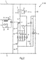
- Fig.2 shows a second circuit 21 of a second oven B2.
- the circuit 21 differs from the circuit 1 in that the main relay 7 is missing, but there is a further relay (“secondary consumer relay” 22) on the clock circuit 23.
- the secondary consumer relay 22 is electrically connected in series with the secondary consumers 16, 17 and 19, so that they can advantageously also be operated when the radiators 2 to 5 are switched off by continuously opening the heating circuit relay 10.
- the cooling fan motor 19 can now be operated independently of the radiators 2 to 5 by the baking oven B2, for example in order to allow a cooling fan motor 19 to run on and a dewatering associated therewith in a simple manner.
- the heating circuit relay 10 has the same function in the circuit 21 as in the circuit 1.
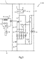
- Figure 3 shows a third circuit 31 of a third oven B3, which differs from the second circuit 21 in that a temperature sensor or temperature sensor 32 for measuring an oven temperature is also connected to the clock circuit 23, for example an NTC resistor or a PTC resistor, for example a platinum measuring resistor, for example of the Pt 500 type.
- the clock circuit 23 can have a suitable measuring circuit for this purpose.
- the temperature sensor 32 also enables temperature control for special programs in which the capillary tube regulator 9 is set in such a way that it has no control function takes over. However, the capillary tube regulator 9 - as in Fig.1 and Fig.2 - Take over a safety function, so that the clock circuit 23 is still particularly simple and inexpensive to implement.
- control and / or regulation functions brought about by the electronic circuit 23 can take place as a function of the cooking space temperature.
- temperature-dependent parameterization of control values for clocked operating modes can be used.
- a follow-up of a cooling fan or the associated cooling fan motor 19 can now be controlled as a function of the cooking chamber temperature by means of the clock circuit 11.
- the clock circuit 11 can also be set up to implement temperature-based door opening detection.
- the clock circuit 11 can be set up to reduce the cooking space temperature on the device side as a function of the electronically measured cooking space temperature.
- the temperature sensor 32 is preferably attached to the holder (not shown) of the sensor of the capillary tube regulator 9.
- a number can also include the specified number as well as a usual tolerance range, as long as this is not explicitly excluded.
Landscapes
- Engineering & Computer Science (AREA)
- Chemical & Material Sciences (AREA)
- Combustion & Propulsion (AREA)
- Mechanical Engineering (AREA)
- General Engineering & Computer Science (AREA)
- Food Science & Technology (AREA)
- Electric Stoves And Ranges (AREA)
Description
Die Erfindung betrifft ein Haushalts-Gargerät, aufweisend mehrere elektrisch betreibbare Heizkörper zum Heizen eines Garraums, einen mechanisch schaltenden Betriebswahlschalter zum Zuschalten mindestens eines Heizkörpers in Abhängigkeit von dessen Schaltstellung, einen mechanischen- Temperaturregler zum Regeln der zugeschalteten Heizkörper in Abhängigkeit von einer Temperatur des Garraums, welcher Temperaturregler mit den Heizkörpern elektrisch in Reihe geschaltet ist, und eine elektronische Schaltung. Die Erfindung ist insbesondere vorteilhaft anwendbar auf Öfen, insbesondere Backöfen.The invention relates to a household cooking appliance, comprising a plurality of electrically operable heating elements for heating a cooking space, a mechanically switching operating mode selector switch for switching on at least one heating element depending on its switching position, a mechanical temperature controller for regulating the connected heating element depending on a temperature of the cooking space, which temperature controller is electrically connected in series with the radiators, and an electronic circuit. The invention is particularly advantageously applicable to ovens, in particular ovens.
Es ist die Aufgabe der vorliegenden Erfindung, die Nachteile des Standes der Technik zumindest teilweise zu überwinden und insbesondere ein Haushalts-Gargerät bereitzustellen, das mit geringen Kosten eine hohe Zahl an Betriebsarten ermöglicht, insbesondere auch mindestens einer Sonderbetriebsart.It is the object of the present invention to at least partially overcome the disadvantages of the prior art and in particular to provide a household cooking appliance which enables a high number of operating modes, in particular also at least one special operating mode, at low cost.
Diese Aufgabe wird gemäß den Merkmalen der unabhängigen Ansprüche gelöst. Bevorzugte Ausführungsformen sind insbesondere den abhängigen Ansprüchen entnehmbar.This object is achieved in accordance with the features of the independent claims. Preferred embodiments can be found in particular in the dependent claims.
Die Aufgabe wird gelöst durch ein Haushalts-Gargerät, aufweisend mehrere elektrisch betreibbare Heizkörper zum Heizen eines Garraums, einen mechanisch schaltenden Betriebswahlschalter zum Zuschalten mindestens eines Heizkörpers in Abhängigkeit von einer nutzerseitig gewählten oder eingestellten Schaltstellung, einen mechanischen Temperaturregler zum Regeln der zugeschalteten Heizkörper in Abhängigkeit von einer Temperatur des Garraums, welcher mechanische Temperaturregler mit den Heizkörpern elektrisch in Reihe geschaltet ist, und eine elektronische Schaltung, wobei ein erstes Relais (im Folgenden ohne Beschränkung der Allgemeinheit als "Heizkreisrelais" bezeichnet) mit den Heizkörpern und dem mechanischen Temperaturregler elektrisch in Reihe geschaltet ist und mittels der elektronischen Schaltung schaltbar ist, die elektronische Schaltung mit dem Betriebswahlschalter verbunden ist, um eine durch den Betriebswahlschalter eingestellte Schaltstellung zu erkennen und die elektronische Schaltung dazu eingerichtet ist, das Heizkreisrelais in Abhängigkeit von der erkannten Schaltstellung des Betriebswahlschalters mit einem vorgegebenen Schaltmuster im laufenden Betrieb ein- und auszuschalten.The object is achieved by a household cooking appliance, comprising a plurality of electrically operable radiators for heating a cooking space, a mechanically switching operating mode selector switch for switching on at least one radiator depending on a switching position selected or set by the user, and a mechanical temperature controller for regulating the connected radiators depending on a temperature of the cooking space, which mechanical temperature controller is electrically connected in series with the radiators, and an electronic circuit, a first relay (hereinafter referred to as "heating circuit relay" without restricting generality) electrically connected in series with the radiators and the mechanical temperature controller is and can be switched by means of the electronic circuit, the electronic circuit is connected to the operating selector switch in order to recognize a switching position set by the operating selector switch and the electr Onical circuit is set up to switch the heating circuit relay on and off as a function of the detected switching position of the operating selector switch with a predetermined switching pattern during operation.
Dieses Haushalts-Gargerät weist den Vorteil auf, dass es wie ein rein mechanisch geregeltes Gargerät arbeiten kann, wobei bzw. solange das Heizkreisrelais im laufenden Betrieb dauerhaft geschlossen ist, was einen besonders preisgünstigen Aufbau ermöglicht. Zusätzlich ist das Haushalts-Gargerät in der Lage, die Heizkörper mittels einer besonders einfachen und preiswerten elektronischen Einheit über eine entsprechende Ansteuerung des Heizkreisrelais im laufenden Betrieb schaltend zu betreiben. Die elektronische Einheit kann einfach gehalten werden, da grundsätzliche Funktionalitäten wie eine Temperatureinstellung, eine Temperaturmessung und eine Regelung bereits durch den sehr kostengünstigen mechanischen Temperaturregler abgedeckt sind. Ein solches Haushalts-Gargerät ist nur geringfügig teurer als ein rein mechanisch geregeltes Gargerät, das eine elektronische Uhr für eine Uhrenanzeige oder für die Bereitstellung eines zeitgesteuerten Betriebs (d.h., eines zeitbegrenzten oder zeitversetzten Betriebs) aufweist, aber erheblich preisgünstiger als ein rein elektronisch geregeltes Gargerät.This household cooking appliance has the advantage that it can work like a purely mechanically controlled cooking appliance, with or as long as the heating circuit relay is permanently closed during operation, which enables a particularly inexpensive construction. In addition, the household cooking appliance is able to operate the radiators during operation by means of a particularly simple and inexpensive electronic unit via a corresponding control of the heating circuit relay. The electronic unit can be kept simple, since basic functionalities such as temperature setting, temperature measurement and regulation are already covered by the very inexpensive mechanical temperature controller. Such a household cooking appliance is only slightly more expensive than a purely mechanically controlled cooking appliance which has an electronic clock for a clock display or for the provision of time-controlled operation (i.e., time-limited or time-shifted operation), but is considerably cheaper than a purely electronically controlled cooking appliance ,
Die Funktionalität, das Heizkreisrelais im laufenden Betrieb zu schalten, kann auch als eine Sonderfunktionalität bezeichnet werden. Eine Betriebsart, bei der das Heizkreisrelais im laufenden Betrieb geschaltet wird, kann auch als eine Sonderbetriebsart bezeichnet werden. Eine Sonderfunktion kann beispielsweise die Funktion "Temperaturabsenkung" sein. Bei dieser wird eine Garraumtemperatur mittels des mechanischen Tempertaturreglers auf einen vorgegebenen Sollwert eingeregelt wird. Liegt der Sollwert z.B. oberhalb eines vorgegebenen Schwellwerts, werden nach einer, ggf. temperaturabhängigen, Zeitdauer die Heizkörper schaltend, insbesondere taktend, betrieben, um die Garraumtemperatur abzusenken, z.B. um 30 °C. Dadurch kann beispielsweise eine Temperatur eines Sichtfensters einer Garraumtür unterhalb eines gewünschten Werts gehalten werden, was eine Nutzersicherheit erhöht. Ein Garergebnis wird durch die Temperaturabsenkung nicht oder nur geringfügig geändert. Ggf. mag sich eine Gardauer verlängern. Eine Betriebsart, welche die Sonderfunktion "Temperaturabsenkung" aufweist, kann selbst eine Sonderbetriebsart ("Sicherheitsgaren") sein. Diese Sonderbetriebsart kann als eine "hybride" Betriebsart angesehen werden, falls sie herkömmliche, mittels des Temperaturreglers temperaturregelnde Betriebsabschnitte und mittels des Heizkörperrelais schaltend, insbesondere taktend, betriebene Betriebsabschnitte aufweist.The functionality of switching the heating circuit relay during operation can also be described as a special functionality. An operating mode in which the heating circuit relay is switched during operation can also be referred to as a special operating mode. A special function can be, for example, the "temperature reduction" function. In this case, a cooking space temperature is adjusted to a predetermined setpoint by means of the mechanical temperature controller. If the setpoint is, for example, above a predetermined threshold value, the radiators are switched, in particular clocking, after a, possibly temperature-dependent, period of time in order to lower the cooking space temperature, for example by 30 ° C. In this way, for example, a temperature of a viewing window of a cooking space door can be kept below a desired value, which increases user safety. A cooking result is not or only slightly changed by the temperature reduction. Possibly. may extend the cooking time. An operating mode that has the special function "temperature reduction" can itself be a special operating mode ("safety cooking"). This special operating mode can be regarded as a "hybrid" operating mode if it has conventional operating sections which regulate the temperature by means of the temperature controller and which operate by switching, in particular clocking, using the radiator relay.
Eine weitere mögliche Sonderbetriebsart kann die Energiesparbetriebsart (sog. "Energiesparmodus") sein, bei der eine vorgegebene Wärmemenge pro Zeiteinheit in den Garraum eingebracht wird. Dies kann durch einen getakteten Betrieb der verwendeten Heizkörper mit einem vorgegebenen Tastgrad geschehen. Eine Regelung der Garraumtemperatur findet hierbei nicht statt. Eine andere Sonderbetriebsart kann ein Niedrigtemperaturgaren oder eine Einfachbratautomatik sein.Another possible special operating mode can be the energy-saving mode (so-called “energy-saving mode”), in which a predetermined amount of heat is introduced into the cooking space per unit of time. This can be done by clocked operation of the radiators used with a predetermined duty cycle. The cooking chamber temperature is not regulated here. Another special mode of operation can be low-temperature cooking or a simple automatic roasting.
Das Heizkreisrelais kann auch zur Realisierung eines zeitbegrenzten Betriebs oder eines zeitversetzten Betriebs geschaltet werden, was aber nicht als eine Sonderfunktionalität angesehen wird. Insbesondere mag ein solches Schalten der Heizkörper nicht als im laufenden Betrieb angesehen werden.The heating circuit relay can also be switched to implement time-limited operation or time-shifted operation, but this is not considered a special functionality. In particular, such a switching of the radiators may not be considered as being in operation.
Dass die elektronische Schaltung dazu eingerichtet ist, das Heizkreisrelais in Abhängigkeit von der erkannten Schaltstellung und damit Betriebsart zu schalten, umfasst, dass das Heizkreisrelais im laufenden Betrieb ein- und ausgeschaltet wird. Dies umfasst ein Schalten mit einem vorgegebenen Schaltmuster oder Schaltregel. Insbesondere kann das Ein- und Ausschalten ein taktendes Schalten umfassen, z.B. mit einem vorgegebenen Tastgrad, einer vorgegebenen Impulsdauer usw.The fact that the electronic circuit is set up to switch the heating circuit relay as a function of the detected switching position and thus the operating mode means that the heating circuit relay is switched on and off during operation. This includes switching with a predetermined switching pattern or switching rule. In particular, the switching on and off can include clocked switching, e.g. with a predefined duty cycle, a predefined pulse duration etc.
Das Haushalts-Gargerät weist mindestens einen Garraum auf. Das Haushalts-Gargerät weist mindestens eine Ofenfunktionalität auf, ggf. auch eine Dampfzugabefunktionalität, insbesondere eine Dampfgarfunktionalität. Das Haushalts-Gargerät kann ein eigenständiges Gargerät oder eine Gargeräts/Kochfeld-Kombination bzw. Herd sein.The household cooking appliance has at least one cooking space. The household cooking appliance has at least one oven functionality, possibly also a steam addition functionality, in particular a steam cooking functionality. The household cooking device can be an independent cooking device or a cooking device / hob combination or stove.
Die Heizkörper können beispielsweise mindestens einen Oberhitze- oder Grillheizkörper, einen Unterhitzeheizkörper und/oder einen Ring- oder Umluftheizkörper aufweisen. Diese Heizkörper können Widerstandsheizkörper sein.The radiators can have, for example, at least one top heat or grill radiator, a bottom heat radiator and / or a ring or circulating air radiator. These radiators can be resistance radiators.
Der mechanisch schaltende Betriebswahlschalter ist dazu eingerichtet, mittels einer manuellen Betätigung mindestens einen zugehörigen elektrischen Kontakt in Abhängigkeit von der gewählten bzw. betätigten Schaltstellung und damit Betriebsart zu öffnen oder zu schließen. Insbesondere kann durch das Öffnen oder Schließen des mindestens einen Kontakts mindestens ein Heizkörper zum Betreiben unter der eingestellten Betriebsart zugeschaltet werden. Der Betriebswahlschalter kann für verschiedene Schaltstellungen bzw. Betriebsarten unterschiedliche Heizkörper oder Kombinationen von Heizkörpern zuschalten. Der Betriebswahlschalter kann auch als Vorwahlschalter bezeichnet werden.The mechanically switching mode selector switch is set up to open or close at least one associated electrical contact as a function of the selected or actuated switching position and thus the operating mode by means of manual actuation. In particular, by opening or closing the at least one contact, at least one heating element can be switched on for operation under the set operating mode. The operating selector switch can be used for different switching positions or operating modes switch on different radiators or combinations of radiators. The operating selector switch can also be referred to as a preselection switch.
Der mechanische Temperaturregler ist dazu eingerichtet, in Abhängigkeit von einer von einem Nutzer daran eingestellten Soll-Temperatur die Garraumtemperatur zu regeln. Dies geschieht ohne elektronische Regelungsbeiträge, sondern mechanisch bzw. elektromechanisch, z.B. mittels eines Kapillarrohrreglers. Ein mechanischer Temperaturregler ist sehr preiswert und robust.The mechanical temperature controller is set up to regulate the cooking space temperature as a function of a target temperature set there by a user. This is done without electronic regulatory contributions, but mechanically or electromechanically, e.g. using a capillary tube regulator. A mechanical temperature controller is very inexpensive and robust.
Der mechanische Temperaturregler kann auch als elektromechanischer Temperaturregler, mechanischer Thermoregler oder Thermostat bezeichnet werden. Der mechanische Temperaturregler kann beispielsweise ein Kapillarrohrregler, ein Bimetallschalter usw. sein.The mechanical temperature controller can also be referred to as an electromechanical temperature controller, mechanical thermoregulator or thermostat. The mechanical temperature controller can be, for example, a capillary tube controller, a bimetal switch, etc.
Der mechanische Temperaturregler ist mit den Heizkörpern elektrisch in Reihe geschaltet, so dass ein Stromfluss durch die Heizkörper durch den mechanischen Temperaturregler ermöglicht wird. Liegt die an dem mechanischen Temperaturregler anliegende Temperatur oberhalb der eingestellten Soll-Temperatur, ist ein elektrischer Kontakt des mechanischen Temperaturreglers offen, und es fließt kein Strom durch die Heizkörper. Liegt die an dem mechanischen Temperaturregler anliegende Temperatur unterhalb der eingestellten Soll-Temperatur, ist der elektrische Kontakt des Temperaturreglers geschlossen, und es kann Strom durch die (zugeschalteten) Heizkörper fließen.The mechanical temperature controller is electrically connected in series with the radiators, so that current can flow through the radiators through the mechanical temperature controller. If the temperature at the mechanical temperature controller is above the set target temperature, an electrical contact of the mechanical temperature controller is open and no current flows through the radiators. If the temperature at the mechanical temperature controller is below the set target temperature, the electrical contact of the temperature controller is closed and current can flow through the (switched on) radiators.
Die elektronische Schaltung kann eine einfache elektronische Schaltung mit einem integrierten Schaltkreis - z.B. einem Controller - sein, der das Heizkreisrelais ansteuern bzw. schalten kann. Das Heizkreisrelais kann ein Bauteil der elektronischen Schaltung sein. Die elektronische Schaltung kann das Heizkreisrelais taktend, d.h. insbesondere, mit einem vorgegebenen Tastgrad und einer vorgegebenen Periodendauer, schalten. Die elektronische Schaltung kann das Heizkreisrelais aber auch für mindestens eine bestimmte Betriebsart geschlossen halten. Allgemein kann die elektronische Schaltung mindestens ein Relais zum Schalten mindestens eines Verbrauchers (insbesondere Heizkörpers und/oder Nebenverbrauchers) schalten und insbesondere aufweisen, was eine besonders kompakte Schaltung ermöglicht.The electronic circuit can be a simple electronic circuit with an integrated circuit - for example a controller - which can control or switch the heating circuit relay. The heating circuit relay can be a component of the electronic circuit. The electronic circuit can switch the heating circuit relay clocking, ie in particular with a predetermined duty cycle and a predetermined period. The electronic circuit can also keep the heating circuit relay closed for at least one specific operating mode. In general, the electronic circuit can switch and in particular have at least one relay for switching at least one consumer (in particular a radiator and / or secondary consumer), which enables a particularly compact circuit.
Das Heizkreisrelais kann ein elektrisch angesteuertes, mechanisch schaltendes Relais sein. Das Heizkreisrelais kann alternativ ein elektronisch angesteuertes Schaltelement wie ein Triac o.ä. sein. Unter einem Heizkreisrelais kann also allgemein ein elektrisch oder elektronisch angesteuertes Schaltelement verstanden werden.The heating circuit relay can be an electrically controlled, mechanically switching relay. The heating circuit relay can alternatively be an electronically controlled switching element such as a triac or similar. his. A heating circuit relay can therefore generally be understood to mean an electrically or electronically controlled switching element.
Das Heizkreisrelais ist mit den (zugeschalteten) Heizkörpern und dem elektrischen Kontakt des mechanischen Temperaturreglers elektrisch in Reihe geschaltet, was eine besonders einfache Schaltung ermöglicht.The heating circuit relay is electrically connected in series with the (connected) radiators and the electrical contact of the mechanical temperature controller, which enables particularly simple switching.
Es ist eine Ausgestaltung, dass die elektronische Schaltung dazu eingerichtet ist, das Heizkreisrelais für mindestens eine Sonderbetriebsart (z.B. für eine Energiesparbetriebsart) im laufenden Betrieb taktend zu schalten und mindestens eine andere, herkömmliche Betriebsart schließend zu schalten bzw. dauerhaft geschlossen zu halten. Dabei wird ausgenutzt, dass mit mechanischen Temperaturreglern bei geringen Temperaturen kein befriedigendes Garergebnis erlangt wird, da die mechanischen Temperaturregler dann eine zu hohe Trägheit aufweisen. Somit kann der mechanische Temperaturregler für hohe Temperaturen wie bisher bei mechanisch geregelten Öfen zur Temperaturregelung eingesetzt werden, insbesondere auch bei üblichen Betriebsarten wie einer Grillbetriebsart, einer Umluft- oder Heißluft-Betriebsart, einer Ober- und/oder Unterhitze-Betriebsart usw. Bei niedrigen Temperaturen ergibt jedoch ein getakteter Niedrigtemperatur-Betrieb der Heizkörper bessere Garergebnisse. Der getaktete Betrieb mag dabei nur gesteuert sein. Der mechanische Temperaturregler ist dann vorzugsweise so eingestellt, dass er während des Betriebsablaufs der Niedrigtemperaturbetriebsart geschlossen bleibt. Er kann dann als ein zusätzlicher Überhitzungsschutz verwendet werden. Eine Niedrigtemperaturbetriebsart kann z.B. ein Sanftgaren (auch als Niedrigtemperaturgaren bekannt) oder ein Energiesparmodus sein.It is an embodiment that the electronic circuit is set up to switch the heating circuit relay for at least one special operating mode (e.g. for an energy-saving operating mode) during operation and to switch at least one other, conventional operating mode to close or to keep it permanently closed. This takes advantage of the fact that a satisfactory cooking result is not achieved with mechanical temperature controllers at low temperatures, since the mechanical temperature controllers then have too high an inertia. Thus, the mechanical temperature controller for high temperatures can be used as before in mechanically controlled ovens for temperature control, in particular also in conventional operating modes such as a grill mode, a circulating air or hot air mode, an upper and / or lower heat mode, etc. At low temperatures However, clocked low-temperature operation of the radiators gives better cooking results. The clocked operation may only be controlled. The mechanical temperature controller is then preferably set so that it remains closed during the operating sequence of the low-temperature operating mode. It can then be used as additional protection against overheating. A low temperature mode can e.g. soft cooking (also known as low temperature cooking) or energy saving mode.
Es ist noch eine Ausgestaltung, dass elektronische Schaltung eine elektronische Uhrschaltung ("Elektronikuhr") zum zeitbegrenzten und/oder zeitversetzten Betreiben des mindestens einen Heizkörpers ist. Eine solche Uhrschaltung ist preisgünstig verfügbar und kommt insbesondere mit wenigen elektronischen Bauteilen aus, z.B. mit einem Mikrocontroller. Die Uhrschaltung kann insbesondere einen Mikrocontroller, das Heizkreisrelais zur Steuerung eines Stromflusses zumindest durch die Heizkörper und eine Verarbeitung eines von dem Betriebswahlschalter kommenden Eingangssignals aufweisen. Die elektronische Uhrschaltung kann in dieser Ausgestaltung also nun auch dazu verwendet werden, um Verbraucher (insbesondere Heizkörper) in einem laufenden Betrieb zu steuern oder zu regeln.It is another embodiment that the electronic circuit is an electronic clock circuit ("electronic clock") for the time-limited and / or time-delayed operation of the at least one radiator. Such a clock circuit is available inexpensively and in particular requires only a few electronic components, for example a microcontroller. The clock circuit can in particular have a microcontroller, the heating circuit relay for controlling a current flow at least through the radiators and a processing of an input signal coming from the operating selector switch. The In this embodiment, electronic clock circuit can now also be used to control or regulate consumers (in particular radiators) during operation.
Es ist eine Ausgestaltung davon, dass das Heizkreisrelais zum zeitgesteuerten zeitbegrenzten oder zeitversetzten Betriebs ein- und ausschaltbar ist. In anderen Worten kann das Relais, das bei herkömmlichen Uhrschaltungen zum zeitgesteuerten (d.h., zum zeitbegrenzten oder zeitversetzten) Betrieb der Heizkörper verwendet wird, nun zusätzlich zum Ein- und Ausschalten der Heizkörper im laufenden Betrieb verwendet werden. Dies ergibt den Vorteil, dass herkömmliche Uhrschaltungen nur geringfügig modifiziert zu werden brauchen, ggf. auch nur durch eine Anpassung ihrer Software oder Firmware.It is an embodiment of the fact that the heating circuit relay can be switched on and off for time-controlled, time-limited or time-shifted operation. In other words, the relay that is used in conventional clock circuits for time-controlled (i.e., time-limited or time-shifted) operation of the radiators can now also be used to switch the radiators on and off during operation. This has the advantage that conventional clock circuits only need to be modified slightly, possibly only by adapting their software or firmware.
Es ist eine weitere Ausgestaltung, dass der Betriebswahlschalter ein Drehwählschalter ist, der eine Kodierschalterplatine aufweist, deren Ausgang mit einem Eingang der elektronischen Schaltung verbunden ist. Alternativ kann der Drehwählschalter anstelle einer Kodierschalterplatine einfache geschaltete Kontakte aufweisen. Diese Ausgestaltungen ergeben den Vorteil, dass eine Information über eine gewählte Betriebsstellung bzw. Betriebsart an die elektronische Schaltung einfach und preiswert übermittebar ist.It is a further embodiment that the mode selector switch is a rotary selector switch that has a coding switch circuit board, the output of which is connected to an input of the electronic circuit. Alternatively, the rotary selector switch can have simple switched contacts instead of a coding switch board. These configurations result in the advantage that information about a selected operating position or operating mode can be transmitted to the electronic circuit simply and inexpensively.
Es ist noch eine weitere Ausgestaltung, dass die elektronische Schaltung ein Hauptrelais aufweist, das in Reihe mit den Heizkörpern und mit Nebenverbrauchern des Haushalts-Gargeräts geschaltet ist. Dadurch können besonders viele, insbesondere alle, Verbraucher mittels nur eines Relais gemeinsam abgeschaltet werden.It is yet another embodiment that the electronic circuit has a main relay which is connected in series with the radiators and with auxiliary consumers of the household cooking appliance. As a result, a particularly large number, in particular all, of consumers can be switched off together by means of only one relay.
Zu Nebenverbrauchern können beispielsweise eine Backofenbeleuchtung (z.B. eine Backofenlampe), ein Umluftmotor, eine Backofenbetriebsanzeigelampe und/oder ein Kühlgebläsemotor gehören.Auxiliary consumers can include, for example, an oven light (e.g. an oven lamp), a forced-air motor, an oven operating indicator lamp and / or a cooling fan motor.
Es ist ferner eine Ausgestaltung, dass die elektronische Schaltung ein weiteres Relais ("Nebenverbraucherrelais") schalten kann, das in Reihe mit zumindest einem Nebenverbraucher des Haushalts-Gargeräts und unabhängig, z.B. parallel, zu den Heizkörpern geschaltet ist. Eine Heizkörperleistung wird insbesondere nicht über das Nebenverbraucherrelais geschaltet. Dadurch kann das Nebenverbraucherrelais kostengünstig ausgeführt werden, da nur kleine Ströme geschaltet werden. Ferner kann der zumindest eine Nebenverbraucher so auch unabhängig von den Heizkörpern geschaltet werden. Dies ermöglicht eine flexiblere Möglichkeit eines unabhängigen - z.B. auch zeitlich versetzten - Betriebs von Heizkörpern und Nebenverbrauchern. Insbesondere können die Heizkörper mittels eines gemeinsamen Relais (nämlich des Heizkreisrelais) abgeschaltet werden, was eine besonders hohe Sicherheit ermöglicht, während der zumindest eine Nebenverbraucher weiterhin betreibbar ist. Die elektronische Schaltung kann das Nebenverbraucherrelais aufweisen bzw. das Nebenverbraucherrelais kann ein Bauelement der elektronischen Uhrschaltung sein, was eine besonders kompakte Schaltung ermöglicht.It is also an embodiment that the electronic circuit can switch a further relay ("secondary consumer relay"), which is connected in series with at least one secondary consumer of the household cooking appliance and independently, for example in parallel, to the radiators. A radiator output is not switched in particular via the auxiliary consumer relay. As a result, the secondary consumer relay can be implemented inexpensively, since only small currents are switched. Furthermore, the at least one Ancillary consumers can also be switched independently of the radiators. This enables a more flexible option for independent - for example, time-shifted - operation of radiators and auxiliary consumers. In particular, the radiators can be switched off by means of a common relay (namely the heating circuit relay), which enables a particularly high level of safety while the at least one secondary consumer can still be operated. The electronic circuit can have the secondary consumer relay or the secondary consumer relay can be a component of the electronic clock circuit, which enables a particularly compact circuit.
Es ist außerdem eine Ausgestaltung, dass zumindest ein Kühlgebläsemotor in Reihe zu dem Nebenverbraucherrelais und insbesondere unabhängig, z.B. parallel, zu den anderen Verbrauchern angeordnet ist. Dadurch kann der Kühlgebläsemotor mittels der elektronischen Schaltung unabhängig zumindest zu den Heizkörpern (und ggf. auch zu anderen Nebenverbrauchern) geschaltet (z.B. an- oder ausgeschaltet) werden, insbesondere temperatur- oder zeitgesteuert. Die sonst für mechanisch geregelte Gargeräte übliche Steuerung eines Lüfternachlaufs über einen Temperaturbegrenzer (z.B. einen Klixon) kann entfallen. Des Weiteren ist es gegenüber heute bekannten Schaltungen von mechanisch geregelten Geräten einfacher möglich, die Ansteuerung und Funktion eines von dem Kühlgebläsemotor angetriebenen Kühllüfters in der Endprüfung zu testen. Bei der sonst üblichen Ansteuerung des Kühllüfters über einen Temperaturbegrenzer ist die Überprüfung der funktionellen Auswirkung des Schaltens des Temperaturbegrenzers nur mit Zusatzaufwand möglich, wie z.B. durch eine aufwändige Erwärmung des Temperaturbegrenzers oder durch ein zusätzliches Überbrücken des Temperaturbegrenzers. Durch die Integration der Funktion in die Uhrschaltung bzw. elektronische Schaltung kann dies vorteilhafterweise über das Einschalten des Nebenverbraucherrelais mit Hilfe eines Testprogrammes erfolgen.It is also an embodiment that at least one cooling fan motor in series with the auxiliary consumer relay and in particular independently, e.g. parallel to the other consumers. As a result, the cooling fan motor can be switched (e.g. switched on or off) independently of the radiators (and possibly also to other secondary consumers), in particular temperature or time-controlled, by means of the electronic circuit. The control of a fan run-on via a temperature limiter (e.g. a Klixon), which is otherwise common for mechanically controlled cooking appliances, can be omitted. Furthermore, compared to circuits of mechanically controlled devices known today, it is easier to test the control and function of a cooling fan driven by the cooling fan motor in the final test. With the otherwise usual control of the cooling fan via a temperature limiter, checking the functional effect of switching the temperature limiter is only possible with additional effort, e.g. through complex heating of the temperature limiter or by additional bridging of the temperature limiter. By integrating the function into the clock circuit or electronic circuit, this can advantageously be done by switching on the auxiliary consumer relay using a test program.
Es ist eine Weiterbildung davon, dass die Backofenbeleuchtung, der Umluftmotor und die Backofenbetriebsanzeigelampe (ggf. alle befindlichen Nebenverbraucher bis auf den Kühlgebläsemotor, falls vorhanden) jeweils in Reihe mit dem Betriebswahlschalter verbunden sind, insbesondere so, dass in einer Aus-Stellung des Betriebswahlschalters die Stromkreise dieser Verbraucher unterbrochen sind. Dadurch kann erreicht werden, dass nur der Kühlgebläsemotor auch in einer Aus-Stellung des Betriebswahlschalters betreibbar ist.It is a further development of the fact that the oven lighting, the circulating air motor and the oven operating indicator lamp (possibly all the secondary consumers located apart from the cooling fan motor, if present) are each connected in series with the operating selector switch, in particular in such a way that when the operating selector switch is in the off position, the Circuits of these consumers are interrupted. It can thereby be achieved that only the cooling fan motor can also be operated in an off position of the operating selector switch.
Insbesondere kann zumindest ein Kühlgebläsemotor in Abhängigkeit von der Stellung des Drehwählers unabhängig zu den anderen Verbrauchern geschaltet werden und in dieser Stellung des Drehwählers in Reihe zu dem Hauptrelais angeordnet sein. Auch kann zumindest ein Kühlgebläsemotor in Abhängigkeit von der Stellung des Drehwählers unabhängig zu den anderen Verbrauchern geschaltet werden und in dieser Stellung des Drehwählers in Reihe zu dem Nebenverbraucherrelais angeordnet sein.In particular, at least one cooling fan motor can be switched independently of the other consumers depending on the position of the rotary selector and can be arranged in series with the main relay in this position of the rotary selector. At least one cooling fan motor can also be switched independently of the other consumers as a function of the position of the rotary selector and can be arranged in series with the secondary consumer relay in this position of the rotary selector.
Es ist auch eine Ausgestaltung, dass die elektronische Schaltung mit einem Temperatursensor oder Temperaturfühler zum Messen einer Garraumtemperatur verbunden ist. Durch die Integration der einfachen "elektronischen Temperaturmessung" wird auf preiswerte Weise die Möglichkeit geschaffen, dass durch die elektronische Schaltung bewirkte Steuer- und/oder Regelungsfunktionen in Abhängigkeit der Garraumtemperatur erfolgen können. Beispielsweise kann nun auch bei einem schaltenden, insbesondere getakteten, Betrieb der Heizkörper über die elektronische Schaltung eine Anpassung der elektronischen Parameter (z.B. des Taktverhältnisses) an die aktuell vorliegende Garraumtemperatur erreicht werden. So kann die elektronische Schaltung die Garraumtemperatur durch Schalten des Heizkreisrelais regeln oder temperaturabhängig steuern. Der weiterhin vorhandene mechanische Temperaturregler kann dabei insbesondere zur Sicherstellung einer Betriebssicherheit, insbesondere vor einer Überhitzung, verwendet werden. So kann beispielsweise auch vermieden werden, dass die elektronische Schaltung erhöhten Sicherheitsanforderungen genügen muss, was sie erheblich verteuern würde.It is also an embodiment that the electronic circuit is connected to a temperature sensor or temperature sensor for measuring a cooking space temperature. By integrating the simple "electronic temperature measurement", the possibility is created in an inexpensive manner that control and / or regulation functions brought about by the electronic circuit can take place as a function of the cooking space temperature. For example, when switching, in particular clocked, operation of the radiators via the electronic circuit, the electronic parameters (e.g. the cycle ratio) can now be adapted to the current cooking chamber temperature. The electronic circuit can regulate the cooking space temperature by switching the heating circuit relay or control it depending on the temperature. The mechanical temperature controller that is still present can be used in particular to ensure operational safety, in particular against overheating. For example, it can also be avoided that the electronic circuit must meet increased safety requirements, which would make it considerably more expensive.
Es ist eine Weiterbildung, dass eine Parametrisierung von Steuerwerten für getaktete Betriebsarten verwendet wird, was eine höhere Energieeinsparung ermöglicht (z.B. im Energiesparmodus). Außerdem wird dadurch eine Zuverlässigkeit verbessert, ein gutes Garergebnis zu erzielen, da ein besser angepasster Energieeintrag möglich wird.It is a further development that a parameterization of control values for clocked operating modes is used, which enables higher energy savings (e.g. in energy saving mode). This also improves the reliability of achieving a good cooking result, since a better adapted energy input is possible.
Es ist eine spezielle Weiterbildung, dass eine temperaturabhängige Parametrisierung von Steuerwerten für getaktete Betriebsarten verwendet wird, was eine noch höhere Energieeinsparung ermöglicht. Durch die elektronische Temperaturmessung können folglich besser angepasste Steuerungs- / Regelungsparameter für einen geschalteten, insbesondere getakteten, Betrieb der Heizkörper im laufenden Betrieb bereitgestellt werden. Die Parameter für den getakteten Betrieb können somit in Abhängigkeit der Garraumtemperatur variiert werden, um eine höhere Energieeinsparung bei verbesserter Garqualität zu erreichen.It is a special further development that a temperature-dependent parameterization of control values for clocked operating modes is used, which enables even greater energy savings. The electronic temperature measurement consequently makes it possible to provide better adapted control parameters for a switched, in particular clocked, operation of the radiators during operation. The parameters for the clocked operation can thus depend on the cooking space temperature can be varied to achieve higher energy savings with improved cooking quality.
In einer weiteren Weiterbildung ist ein Nachlauf eines Kühllüfters (z.B. dessen Dauer oder "Nachlaufdauer") und/oder dessen Drehzahl in Abhängigkeit von der Garraumtemperatur steuerbar, beispielsweise durch eine temperaturabhängige Schaltung des Nebenverbraucherrelais. Dadurch ergibt sich der Vorteil, dass die Nachlaufzeit nicht unnötig lang ist, aber eine ausreichende Abkühlung und eine Entwrasung des Garraums erreichbar ist. Der Energieverbrauch und die Lärmbelästigung während des Lüfternachlaufs werden dadurch reduziert.In a further development, a run-on of a cooling fan (e.g. its duration or "run-on period") and / or its speed can be controlled as a function of the cooking space temperature, for example by a temperature-dependent switching of the auxiliary consumer relay. This has the advantage that the run-on time is not unnecessarily long, but sufficient cooling and dewatering of the cooking space can be achieved. This reduces energy consumption and noise pollution during fan run-on.
Auch ist es eine Weiterbildung, dass in die elektronische Schaltung eine temperaturbasierte Türöffnungserkennung integriert ist, um beispielsweise einen Folgebetrieb (d.h. einen Betrieb nach Ablauf einer voreingestellten Gardauer) ohne Nachteile für das Garergebnis sicherzustellen. Dies kann mit Hilfe der elektronischen Temperaturmessung und eines entsprechend implementierten Algorithmus für die Auswertung des Temperaturverlaufes des Gargeräts umgesetzt sein. Beispielsweise kann die Backofentemperatur nach Erkennen eines Einbruchs der Garraumtemperatur anders gesteuert und/oder geregelt werden, um den Einfluss dieses Temperatureinbruchs auszugleichen. Insbesondere kann der getaktete Betrieb für die benötigte Ausgleichsdauer unterbrochen werden. Der Temperatureinbruch kann z.B. durch ein Öffnen einer Garraumtür bewirkt worden sein.It is also a further development that a temperature-based door opening detection is integrated in the electronic circuit, for example to ensure subsequent operation (i.e. operation after a preset cooking time has expired) without disadvantages for the cooking result. This can be implemented with the aid of the electronic temperature measurement and a correspondingly implemented algorithm for evaluating the temperature profile of the cooking device. For example, the oven temperature can be controlled and / or regulated differently after detection of a drop in the cooking space temperature in order to compensate for the influence of this drop in temperature. In particular, the clocked operation can be interrupted for the required compensation period. The drop in temperature can e.g. be caused by opening a cooking chamber door.
Es ist noch eine Weiterbildung, dass die Garraumtemperatur in Abhängigkeit von der elektronisch gemessenen Garraumtemperatur geräteseitig verringerbar ist, insbesondere zeit- und/oder temperaturabhängig steuerbar oder regelbar ist. Dies kann beispielsweise umfassen, dass eine mittels des Thermostaten nutzerseitig eingestellte Garraumtemperatur (z.B. von 270°C) nach einer vorgegebenen Zeitdauer automatisch mittels der elektronischen Schaltung abgesenkt wird (z.B. auf 230°C), um eine Fronttemperatur an der Garraumtür zu begrenzen. Diese Absenkung der Garraumtemperatur kann z.B. durch ein entsprechend langes und/oder häufiges Öffnen des Heizkreisrelais erreicht werden.It is a further development that the cooking space temperature can be reduced on the device side depending on the electronically measured cooking space temperature, in particular can be controlled or regulated as a function of time and / or temperature. This can include, for example, that a cooking space temperature set by the user using the thermostat (e.g. of 270 ° C) is automatically lowered (e.g. to 230 ° C) after a predetermined period of time in order to limit a front temperature on the cooking space door. This lowering of the cooking space temperature can e.g. can be achieved by opening the heating circuit relay for a correspondingly long time and / or frequently.
Vorzugsweise ist der Temperatursensor am Halter des Fühlers des Temperaturreglers (vorzugsweise Kapillarrohrregler), mit dem dieser am oder im Backrohr befestigt wird, angebracht, da dort bei unterschiedlichen Betriebsarten identische Temperaturwerte relativ zur einer Garraummittentemperatur herrschen.The temperature sensor is preferably on the holder of the sensor of the temperature controller (preferably capillary tube controller) with which it is attached to or in the oven. attached, because there are identical temperature values relative to a cooking space center temperature in different operating modes.
Die Aufgabe wird auch gelöst durch ein Verfahren zum Betreiben des Haushalts-Gargeräts wie oben beschrieben, wobei dann, wenn eine Betriebsart gewählt wird, bei der mindestens ein Heizkörper getaktet betrieben wird, der mechanische Temperaturregler auf eine Temperatur gestellt wird, die höher ist als eine zu erwartende maximale Garraumtemperatur, insbesondere auf eine maximal einstellbare Temperatur. So kann besonders sicher und mit einfachen Mitteln verhindert werden, dass der mechanische Temperaturregler bei einem schaltenden, insbesondere getakteten, Betrieb mindestens eines Verbrauchers in dessen Betrieb eingreift, da der mechanische Temperaturregler erwartungsgemäß dann geschlossen bleibt.The object is also achieved by a method for operating the household cooking appliance as described above, wherein when an operating mode is selected in which at least one radiator is operated in a clocked manner, the mechanical temperature controller is set to a temperature which is higher than one maximum cooking space temperature to be expected, in particular to a maximum adjustable temperature. In this way, it can be prevented particularly safely and with simple means that the mechanical temperature controller intervenes in the operation of at least one consumer during switching, in particular clocked operation, since the mechanical temperature controller then remains closed, as expected.
Die Aufgabe wird außerdem gelöst durch Verfahren, die den oben aufgeführten Sonderfunktionen und/oder Sonderbetriebsarten entsprechen, z.B. Temperaturabsenkung, Energiesparbetriebsart usw.The task is also solved by methods which correspond to the special functions and / or special operating modes listed above, e.g. Temperature reduction, energy saving mode, etc.
Die oben beschriebenen Eigenschaften, Merkmale und Vorteile dieser Erfindung sowie die Art und Weise, wie diese erreicht werden, werden klarer und deutlicher verständlich im Zusammenhang mit der folgenden schematischen Beschreibung eines Ausführungsbeispiels, das im Zusammenhang mit den Zeichnungen näher erläutert wird.
- Fig.1
- zeigt eine erste Schaltung eines ersten Backofens;
- Fig.2
- zeigt eine zweite Schaltung eines zweiten Backofens; und
- Fig.3
- zeigt eine dritte Schaltung eines dritten Backofens.
- Fig.1
- shows a first circuit of a first oven;
- Fig.2
- shows a second circuit of a second oven; and
- Figure 3
- shows a third circuit of a third oven.
Zwischen die Heizkörper 2 bis 5 einerseits und den Neutralleiter N andererseits ist ein Temperaturbegrenzer 6 geschaltet. Ferner sind zwischen den Außenleiter L und die Heizkörper 2 bis 5 in Reihe: ein Hauptrelais 7, ein mechanischer Drehwählschalter 8, ein mechanischer-Temperaturregler - hier z.B. ausgebildet als ein nutzereinstellbarer Kapillarrohrregler 9 - und ein Heizkreisrelais 10 geschaltet. Das Hauptrelais 7 und das Heizkreisrelais 10 sind Bauteile einer Uhrschaltung 11.A
Die Uhrschaltung 11 ist als eine elektronische Schaltung aufgebaut und kann außer den Relais 7 und 10 mindestens einen integrierten Schaltkreis (z.B. einen Mikrocontroller, o. Abb.) usw. aufweisen. Die Uhrschaltung 11 dient unter anderem zur Zeitsteuerung des Backofens B1 (z.B. zur Umsetzung einer Timerfunktion und zur Zeitanzeige) und kann dazu eine Anzeigeeinrichtung 12 (z.B. eine 7-Segment-Anzeige) aufweisen. Die Uhrschaltung 11 ist hier direkt zwischen dem Außenleiter L und dem Neutralleiter N angeschlossen. Die Uhrschaltung 11 ist zudem so eingerichtet, dass sie das Heizkreisrelais 10 und/oder das Hauptrelais 7 schalten kann.The
Ferner ist ein Eingang 13 der Uhrschaltung 11 mit einem Ausgang 14 des Drehwählschalters 8 verbunden. Der Drehwählschalter 8 ist dabei mit einer Kodiereinrichtung 15 (z.B. in Form einer Kodierschalterplatine, z.B. auf der Grundlage einer Bitkodierung mittels beispielsweise eines Grey-Codes) ausgestattet, welcher jeder Drehstellung des Drehwählschalters 8 ein Ausgangssignal bzw. eine eindeutige elektrische Schnittstellenkonfiguration zuordnet. Daher kann die Uhrschaltung 11 (z.B. mittels einer geeigneten Auswertelogik oder Auswerteschaltung) erkennen, in welcher Drehstellung sich der Drehwählschalter 8 befindet. Eine Drehstellung des Drehwählschalters 8 kann insbesondere einer jeweiligen Betriebsart entsprechen.Furthermore, an
Der Drehwählschalter 8 ist zudem so ausgebildet und angeordnet, dass er eine Verbindung zwischen dem Hauptrelais 7 und dem Kapillarrohrregler 9, zwischen dem Temperaturbegrenzer 6 und dem Neutralleiter N, zwischen den Heizkörpern 2 bis 5 und dem Heizkreisregler 10, zwischen den Heizkörpern 2 bis 5 und der Uhrschaltung 11, zwischen den Heizkörpern 2 bis 5 und einem Umluftmotor 16 sowie zwischen dem Umluftmotor 16 und dem Neutralleiter N wahlweise schließen und öffnen kann. Alle diese Verbindungen können in Abhängigkeit von der gewählten Drehstellung individuell geschlossen oder geöffnet sein. In einer Aus- oder Null-Stellung, in der keine Betriebsart ausgewählt ist, kann der Drehwählschalter 8 so eingerichtet sein, dass alle Verbindungen geöffnet sind. Insbesondere kann jeder dieser Verbindungen ein mechanischer Einzelschalter Sn (n = 1, ..., 9) des Drehwählschalters 8 zugeordnet sein, welcher dann entsprechend mehrere solcher mechanischen Einzelschalter Sn aufweist. Die Einzelschalter Sn können beispielsweise mittels einer passenden, z.B. mit einem Drehknebel verbundenen, Welle betätigt werden. Grundsätzlich kann jeder Wählstellung des Drehwählschalters 8 eine beliebige, aber feststehende Kombination der Schließzustände (offen/geschlossen) der Einzelschalter Sn zugeordnet sein.The
Die Einzelschalter S1 bis S8 können beispielsweise umfassen: einen Einzelschalter S1 zwischen dem Kapillarrohrregler 9 und dem Heizrelais 7, einen Einzelschalter S2 zwischen dem ersten Grillheizkörper 2 und dem Heizkreisrelais 10, einen Einzelschalter S3 zwischen dem zweiten Grillheizkörper 3 und dem Heizkreisrelais 10, einen Einzelschalter S4 zwischen dem Unterhitzeheizkörper 4 und dem Heizkreisrelais 10, einen Einzelschalter S5 zwischen dem Umluftheizkörper 5 und dem Heizkreisrelais 10, einen Einzelschalter S6 zwischen dem Neutralleiter N und dem Temperaturbegrenzer 6, einen Einzelschalter S7 zwischen den Einzelschaltern S2 bis S5 und einem Signaleingang der Uhrschaltung 11, einen Einzelschalter S8 zwischen dem Einzelschalter S6 und dem Umluftmotor 16 und einen Einzelschalter S9 zwischen den Einzelschaltern S2 bis S5 und dem Umluftmotor 16. Die Uhrschaltung 11 kann die Aus-Stellung des Drehwählschalters 8 durch einen entsprechenden Bitcode - z.B. "000" - erkennen.The individual switches S1 to S8 can include, for example: a single switch S1 between the
Außer dem Umluftmotor 16 sind noch weitere Nebenverbraucher zwischen den Außenleiter L und den Neutralleiter N geschaltet. Beispielsweise ist eine Backofenlampe 17 vorhanden, die einerseits zwischen den Einzelschalter S1 des Drehwählschalters 8 und den Kapillarrohrregler 9 und andererseits zwischen den Temperaturbegrenzer 6 und den Einzelschalter S6 geschaltet ist. Eine Backofenbetriebsanzeigelampe 18 ist zu der Backofenlampe 17 parallel geschaltet. Ein Kühlgebläsemotor 19 ist einerseits direkt mit dem Neutralleiter N verbunden und andererseits zwischen den Einzelschalter S1 des Drehwählschalters 8 und das Hauptrelais 7 geschaltet. Alle beschriebenen Verbraucher 2 bis 5 und 16 bis 19 bis auf die Uhrschaltung 11 sind also elektrisch in Reihe mit dem Hauptrelais 7 geschaltet, so dass bei geöffnetem Hauptrelais 7 diese Verbraucher 2 bis 5 und 16 bis 19 nicht mit elektrischer Spannung versorgt werden und folglich abgeschaltet sind.In addition to the
Zum Betrieb des Backofens 1 dreht ein Nutzer den Drehwählschalter 8 aus seiner Aus- oder Null-Stellung in eine Betriebsstellung, die einer von dem Nutzer gewünschten Betriebsart entspricht. Die Betriebsart kann eine für Backöfen mit mechanischen Backofenreglern (z.B. Kapillarrohrreglern 9) übliche Betriebsart wie eine Grillbetriebsart, eine Unterhitze- und/oder Oberhitze-Betriebsart oder eine Umluftbetriebsart sein. Jedoch ermöglicht das von der Uhrschaltung 11 ansteuerbare Heizkreisrelais 10 auch den schaltenden Betrieb mit Sonderbetriebsarten wie Sanftgaren (Niedrigtemperaturgaren), energiesparend Garen (z.B. einem "Energiesparmodus") usw. Für die üblichen Betriebsarten wird das Heizkreisrelais 10 zum Regeln einer Garraumtemperatur nicht benötigt und ist im laufenden Betrieb dauerhaft geschlossen.To operate the
Stellt ein Nutzer an dem Drehwählschalter 8 beispielsweise die Grillbetriebsart ein, so schließt der Drehwahlschalter 8 den Einzelschalter S1 zwischen dem Kapillarrohrregler 9 und dem Heizrelais 7, den Einzelschalter S6 zwischen dem Neutralleiter N und dem Temperaturbegrenzer 6 sowie die Einzelschalter S2 und S3 zwischen den Grillheizkörpern 2 bzw. 3 und dem Heizkreisrelais 10. Zudem wird der Einzelschalter S7 zwischen den Grillheizkörpern 2 und 3 und der Uhrschaltung 11 geschlossen sein, so dass die Uhrschaltung 11 eine Rückmeldung darüber erhält, dass zumindest an einem der Heizkörper 2 bis 5 eine Spannung anliegt und daher - falls der Temperaturbegrenzer 6 geschlossen ist - der Heizkörper heizt.For example, if a user sets the grill operating mode on the
Hingegen sind die Einzelschalter S4 und S5 offen, so dass die Heizkörper 4 und 5 nicht betrieben werden. Außerdem sind die Einzelschalter S8 und S9 offen, so dass der Umluftmotor 16 nicht betrieben wird.In contrast, the individual switches S4 and S5 are open, so that the
Ferner kann an dem Drehwählschalter 8 nun von der Uhrschaltung 11 ein entsprechender Bit-Code abgelesen werden bzw. wird von dem Drehwählschalter 8 nun ein entsprechender Bit-Code an die Uhrschaltung 11 ausgegeben. Die Uhrschaltung 11 verarbeitet den Bit-Code (z.B. mittels einer entsprechenden Verarbeitungseinrichtung) und schaltet das Heizkreisrelais 10 entsprechend oder belässt es in der Ausgangsstellung. Dadurch wird auch eine elektrische Verbindung zwischen dem Grillheizkörper 2 und dem Kapillarrohrregler 9 hergestellt, so dass der Grillheizkörper 2 nun sowohl an den Außenleiter L als auch an den Neutralleiter N angeschlossen ist und daher mit elektrischer Energie versorgbar ist. Die zugehörige Temperaturregelung erfolgt wie üblich über eine Temperatureinstellung an dem Kapillarrohrregler 9.Furthermore, a corresponding bit code can now be read from the
Über die Uhrschaltung 11 kann ferner ein zeitversetzter und/oder ein zeitbegrenzter Betrieb der Grillbetriebsart eingestellt werden, z.B. beginnend in einer Stunde nach Aktivierung mit einer Dauer von zwei Stunden. Die Uhrschaltung 11 öffnet bzw. schließt dazu das Hauptrelais 7 und das Heizkreisrelais 10 entsprechend.Via the
Wird an dem Drehwählschalter 8 eine Umluftbetriebsart gewählt, so kann anstelle der Schalter S2 und S3 der Schalter S5 geschlossen werden, um nur den Umluftheizkörper 5 zu betreiben. Dabei kann der Schalter S8 geschlossen sein, um auch den Umluftmotor 16 zu betreiben.If an air recirculation mode is selected on the
Für Sonderbetriebsarten ist die Funktionalität des Kapillarrohrreglers 9 nicht ausreichend da es nicht möglich ist, in Abhängigkeit von der gewählten Betriebsart z.B. einen Energieeintrag in den Backofen über Parameter der Uhrschaltung 11 zu steuern. Wird an dem Drehwählschalter 8 eine Sonderbetriebsart ausgewählt, z.B. ein Energiesparmodus, so wird ähnlich zu der Auswahl einer bisher üblichen Betriebsart der passende mindestens eine Heizkörper aus der Gruppe der Heizkörper 2 bis 5 mittels Schließens der entsprechenden Einzelschalter S2 bis S5 zugeschaltet, ggf. auch der Umluftmotor 16.The functionality of the
Im Gegensatz zu einer der üblichen Betriebsarten wird jedoch nun das Heizkreisrelais 10 von der Uhrschaltung 11 ein- und ausschaltend, insbesondere getaktet, angesteuert, so dass auch die passenden Heizkörper 2 bis 5 ein- und ausschaltend, insbesondere getaktet, betrieben werden. Dabei findet insbesondere keine Regelung der Temperatur in einem zugehörigen Garraum oder Ofenraum des Backofens 1 statt bzw. ist die Taktung (z.B. eine Periodendauer, ein Tastgrad usw.) nicht abhängig von einer Ofentemperatur in dem Ofenraum. Dazu kann der Kapillarrohrregler 9 von einem Nutzer auf einen Temperaturwert (an welchem der Kapillarrohrregler 9 öffnet oder unterbricht) eingestellt worden sein, der oberhalb eines in der gewählten Sonderbetriebsart typischerweise erreichbaren Temperaturwerts liegt, beispielsweise auf einen maximal einstellbaren Temperaturwert. Die für die gewählte Sonderbetriebsart geeigneten Taktungsparameter (Periodendauer, Tastgrad usw.) kann die Uhrschaltung 11 anhand des von dem Drehwählschalter 8 übertragenen oder ausgelesenen Bit-Codes bestimmen oder festlegen.In contrast to one of the usual operating modes, however, the
Folglich kann der Backofen 1 Betriebsarten (insbesondere dafür übliche Betriebsarten) mittels einer mechanisch-thermischen Regelung über den mechanisch einstellbaren Drehwählschalter 8 und den Kapillarrohrregler 9 durchführen und in mindestens einer Betriebsart auf einfache und besonders preiswerte Weise einen schaltend, insbesondere getaktet, gesteuerten Heizbetrieb durchführen.Consequently, the
Es kann also kostengünstig eine Funktion, z.B. eine Energiesparbetriebsart und/oder eine Temperaturabsenkung, in Gargeräten mit einer mechanischen Regelung angeboten werden. Die hier als Uhrschaltung 11 ausgebildete Elektronikeinheit kann besonders einfach gehalten werden, da grundsätzliche Funktionalitäten (Temperatureinstellung, Temperaturmessung und Regelung) insbesondere für übliche Betriebsarten bereits durch das sehr kostengünstige mechanische Regelelement (z.B. den Kapillarrohrregler 9) abgedeckt sind.A function, e.g. an energy-saving mode and / or a temperature reduction are offered in cooking devices with mechanical control. The electronic unit designed here as a
Durch die Integration einer solchen einfachen "elektronischen Temperaturmessung" wird auf preiswerte Weise die Möglichkeit geschaffen, dass durch die elektronische Schaltung 23 bewirkte Steuer- und/oder Regelungsfunktionen in Abhängigkeit der Garraumtemperatur erfolgen können. Insbesondere kann eine temperaturabhängige Parametrisierung von Steuerwerten für getaktete Betriebsarten verwendet werden. Ferner ist nun mittels der Uhrschaltung 11 ein Nachlauf eines Kühllüfters bzw. des zugehörigen Kühlgebläsemotors 19 in Abhängigkeit von der Garraumtemperatur steuerbar. Auch kann die Uhrschaltung 11 dazu eingerichtet sein, eine temperaturbasierte Türöffnungserkennung umzusetzen. Zudem kann die Uhrschaltung 11 dazu eingerichtet sein, die Garraumtemperatur in Abhängigkeit von der elektronisch gemessenen Garraumtemperatur geräteseitig zu verringern.By integrating such a simple “electronic temperature measurement”, the possibility is created in an inexpensive manner that control and / or regulation functions brought about by the
Vorzugsweise ist der Temperatursensor 32 am Halter (o. Abb.) des Fühlers des Kapillarrohrreglers 9 befestigt.The
Selbstverständlich ist die vorliegende Erfindung nicht auf die gezeigten Ausführungsbeispiele beschränkt.Of course, the present invention is not limited to the exemplary embodiments shown.
Allgemein kann unter "ein", "eine" usw. eine Einzahl oder eine Mehrzahl verstanden werden, insbesondere im Sinne von "mindestens ein" oder "ein oder mehrere" usw., solange dies nicht explizit ausgeschlossen ist, z.B. durch den Ausdruck "genau ein" usw.In general, "a", "an" etc. can be understood to mean a singular or a plurality, in particular in the sense of "at least one" or "one or more" etc., as long as this is not explicitly excluded, e.g. by the expression "exactly one" etc.
Auch kann eine Zahlenangabe genau die angegebene Zahl als auch einen üblichen Toleranzbereich umfassen, solange dies nicht explizit ausgeschlossen ist.A number can also include the specified number as well as a usual tolerance range, as long as this is not explicitly excluded.
- 11
- Schaltungcircuit
- 22
- Erster GrillheizkörperFirst grill radiator
- 33
- Zweiter GrillheizkörperSecond grill radiator
- 44
- UnterhitzeheizkörperBottom heating element
- 55
- UmluftheizkörperRecirculating air heating
- 66
- TemperaturbegrenzerTemperature
- 77
- Hauptrelaismain relay
- 88th
- Drehwählschalterrotary dial
- 99
- KapillarrohrreglerCapillary tube
- 1010
- HeizkreisrelaisHeizkreisrelais
- 1111
- Uhrschaltungwatch circuit
- 1212
- Anzeigeeinrichtungdisplay
- 1313
- Eingang der UhrschaltungInput of the clock circuit
- 1414
- Ausgang des DrehwählschaltersOutput of the rotary selector switch
- 1515
- Kodiereinrichtungcoding
- 1616
- Umluftmotorrecirculated air motor
- 1717
- Backofenlampeoven light
- 1818
- BackofenbetriebsanzeigelampeOven pilot lamp
- 1919
- KühlgebläsemotorCooling fan motor
- 2121
- Schaltungcircuit
- 2222
- Nebenverbraucher-RelaisIn addition to consumer relay
- 2323
- Uhrschaltungwatch circuit
- 3131
- Schaltungcircuit
- 3232
- Temperatursensortemperature sensor
- AA
- Außenleiterouter conductor
- B1B1
- Backofenoven
- B2B2
- Backofenoven
- B3B3
- Backofenoven
- NN
- Neutralleiterneutral
- S1-S9S1-S9
- EinzelschalterSingle switch
Claims (14)
- Household cooking appliance (B1; B2; B3), having- a plurality of electrically operable heating elements (2-5) for heating a cooking compartment,- a mechanically switching operation selection switch (8) for connecting at least one heating element (2-5) as a function of the switch position thereof,- a mechanical temperature regulator (9) for regulating the connected heating element (2-5) as a function of a temperature of the cooking compartment, which mechanical temperature regulator (9) is connected electrically in series with the heating elements (2-5), and- an electronic circuit (11; 23),
wherein- a heating circuit relay (10) is connected electrically in series with the heating elements (2-5) and the mechanical temperature regulator (9) and is able to be switched by means of the electronic circuit (11; 23) and- the electronic circuit (11; 23) is connected to the operation selection switch (8) in order to identify a switch position set by the operation selection switch (8), characterised in that- the electronic circuit (11; 23) is configured to switch the heating circuit relay (10) on and off during continuous operation as a function of the identified switch position with a predefined switching pattern. - Household cooking appliance (B1; B2; B3) according to claim 1, characterised in that the electronic circuit (11; 23) is configured to connect the heating circuit relay (10) in a timed manner for at least one special operating mode and in a closing manner for at least one further operating mode.
- Household cooking appliance (B1; B2; B3) according to one of the preceding claims, characterised in that the electronic circuit (11; 23) is an electronic timing circuit for the time-controlled operation of the at least one heating element (2-5).
- Household cooking appliance (B1; B2; B3) according to claim 3, characterised in that the heating circuit relay (10) is able to be switched on and off for the time-controlled operation.
- Household cooking appliance (B1; B2; B3) according to one of the preceding claims, characterised in that the operation selection switch (8) is a rotary selection switch, the output of which is connected to an input of the electronic circuit (11; 23).
- Household cooking appliance (B1) according to one of the preceding claims, characterised in that the electronic circuit (11) has a main relay (7), which is connected in series with the heating elements (2-5) and with auxiliary consumers (16-19) of the household cooking appliance (B1).
- Household cooking appliance (B2; B3) according to one of the preceding claims, characterised in that the electronic circuit (23) has an auxiliary consumer relay (22), which is connected in series with at least one auxiliary consumer (16-18) of the household cooking appliance (B2; B3) and is switched independently of the heating elements (2-5).
- Household cooking appliance (B3) according to one of the preceding claims, characterised in that the electronic circuit (23) is connected to a temperature sensor (32) for measuring a cooking compartment temperature and is configured to regulate or control the cooking compartment temperature measured in this way by switching the heating circuit relay.
- Household cooking appliance (B3) according to claim 8, characterised in that a subsequent running of a cooling fan (19) is able to be controlled as a function of the cooking compartment temperature measured by means of the temperature sensor (32).
- Household cooking appliance (B3) according to one of the preceding claims, characterised in that the electronic circuit (23) is configured to use a parameterisation, in particular temperature-dependent parameterisation, of control values for operating modes timed by means of the heating circuit relay (10).
- Household cooking appliance (B3) according to one of claims 8 to 10, characterised in that the electronic circuit (23) is configured for carrying out a door opening identification.
- Household cooking appliance (B3) according to one of claims 8 to 11, characterised in that the cooking compartment temperature is able to be reduced on the appliance side as a function of the cooking compartment temperature measured by means of the temperature sensor (32).
- Household cooking appliance (31) according to one of claims 8 to 12, characterised in that the temperature sensor (32) is attached to a holder of a probe of the mechanical temperature regulator (9), with which it is fastened to or in the cooking compartment.
- Method for operating a household cooking appliance (B1; B2; B3) according to one of the preceding claims, characterised in that when an operating mode is chosen, in which at least one heating element (2-5) is operated in a timed manner, the mechanical temperature regulator (9) is set to a temperature which is higher than a maximum cooking compartment temperature to be anticipated, in particular to a maximum temperature which can be set.
Priority Applications (1)
| Application Number | Priority Date | Filing Date | Title |
|---|---|---|---|
| PL17170859T PL3249302T3 (en) | 2016-05-25 | 2017-05-12 | Domestic cooking device |
Applications Claiming Priority (1)
| Application Number | Priority Date | Filing Date | Title |
|---|---|---|---|
| DE102016209163.8A DE102016209163A1 (en) | 2016-05-25 | 2016-05-25 | Household cooking appliance |
Publications (2)
| Publication Number | Publication Date |
|---|---|
| EP3249302A1 EP3249302A1 (en) | 2017-11-29 |
| EP3249302B1 true EP3249302B1 (en) | 2020-02-19 |
Family
ID=58707403
Family Applications (1)
| Application Number | Title | Priority Date | Filing Date |
|---|---|---|---|
| EP17170859.7A Active EP3249302B1 (en) | 2016-05-25 | 2017-05-12 | Domestic cooking device |
Country Status (4)
| Country | Link |
|---|---|
| EP (1) | EP3249302B1 (en) |
| DE (1) | DE102016209163A1 (en) |
| ES (1) | ES2775761T3 (en) |
| PL (1) | PL3249302T3 (en) |
Families Citing this family (2)
| Publication number | Priority date | Publication date | Assignee | Title |
|---|---|---|---|---|
| WO2021050011A1 (en) * | 2019-09-10 | 2021-03-18 | Mamur Teknoloji Sistemleri San. A.S. | An oven with cooking mode detection device and operation method for the same |
| DE102019216955A1 (en) | 2019-11-04 | 2021-05-06 | BSH Hausgeräte GmbH | Cooking device control with operating mode switch and timer |
Family Cites Families (11)
| Publication number | Priority date | Publication date | Assignee | Title |
|---|---|---|---|---|
| DE3528229A1 (en) * | 1985-08-06 | 1987-02-12 | Bosch Siemens Hausgeraete | ARRANGEMENT FOR CONTROLLING ELECTRICAL CONSUMERS IN OVENS |
| DE3545108A1 (en) * | 1985-12-19 | 1987-07-09 | Bosch Siemens Hausgeraete | Cooker control circuit for cooking food |
| DE3704002A1 (en) * | 1987-02-10 | 1988-08-18 | Buderus Ag | Domestic appliance with forward-tilting door |
| DE60211749D1 (en) | 2001-12-31 | 2006-06-29 | Electrolux Publ Stockholm Ab | METHOD FOR CONTROLLING THE ENERGY RECORDING IN AN OVEN |
| DE10260019B4 (en) * | 2002-12-19 | 2005-11-24 | Miele & Cie. Kg | Household food warmer for keeping food and drinks warm |
| DE10313596A1 (en) * | 2003-03-26 | 2004-10-07 | BSH Bosch und Siemens Hausgeräte GmbH | Cooking oven has a display panel that is controlled so that icons, corresponding to particular oven operating modes, are illuminated when the oven is being used in a particular mode |
| DE102004032074C5 (en) * | 2004-07-02 | 2013-07-04 | Diehl Ako Stiftung & Co. Kg | Cooker timer |
| DE102006022323A1 (en) * | 2006-05-12 | 2007-11-15 | BSH Bosch und Siemens Hausgeräte GmbH | Household appliance`s e.g. electric cooker, circuit arrangement, has switching and relay contacts interconnected such that specific function of switching contacts is assigned based on switching of one of switching and /or relay contacts |
| DE102007056714A1 (en) | 2007-11-26 | 2009-05-28 | BSH Bosch und Siemens Hausgeräte GmbH | Method for operating a cooking appliance and cooking appliance |
| DE102008017782A1 (en) * | 2008-04-08 | 2009-10-15 | BSH Bosch und Siemens Hausgeräte GmbH | Cooking appliance sensor device for cooking appliance, particularly baking oven, has sensor unit of cooking chamber temperature adjusting unit, sensor unit of safety unit, and sensor holding unit |
| DE102011017638A1 (en) * | 2011-04-27 | 2012-10-31 | BSH Bosch und Siemens Hausgeräte GmbH | Method for operating a cooking appliance and control and regulating device for a cooking appliance and cooking appliance |
-
2016
- 2016-05-25 DE DE102016209163.8A patent/DE102016209163A1/en not_active Withdrawn
-
2017
- 2017-05-12 EP EP17170859.7A patent/EP3249302B1/en active Active
- 2017-05-12 PL PL17170859T patent/PL3249302T3/en unknown
- 2017-05-12 ES ES17170859T patent/ES2775761T3/en active Active
Non-Patent Citations (1)
| Title |
|---|
| None * |
Also Published As
| Publication number | Publication date |
|---|---|
| DE102016209163A1 (en) | 2017-11-30 |
| ES2775761T3 (en) | 2020-07-28 |
| EP3249302A1 (en) | 2017-11-29 |
| PL3249302T3 (en) | 2020-07-27 |
Similar Documents
| Publication | Publication Date | Title |
|---|---|---|
| EP2063180B1 (en) | Method for operating a cooking device and cooking device | |
| EP1212570A1 (en) | Control device for a cooker | |
| EP3249302B1 (en) | Domestic cooking device | |
| DE10128369B4 (en) | Cooking device with a steam fan | |
| EP3250002B1 (en) | Domestic cooking device | |
| DE3229193A1 (en) | ENERGY CONTROLLER FOR HOUSEHOLD COOKERS | |
| DE19711291A1 (en) | Process for regulating thermal paths and heating devices in household appliances | |
| DE10128370B4 (en) | Cooking appliance with a cooling fan | |
| DE102006038832A1 (en) | Method and circuit arrangement for controlling at least one heating element of a heater | |
| EP2837890A2 (en) | Method for operating a gas oven and gas oven | |
| EP3250001B1 (en) | Domestic cooking device | |
| EP2896889B1 (en) | Method for operating a cooking device with a cooking hob and cooking device | |
| WO2003058365A2 (en) | Heating device comprising a flexible heating element | |
| DE1957702A1 (en) | Temperature control circuit | |
| EP3816517B1 (en) | Cooking device controller with operating mode switch and timer | |
| DE2715768C2 (en) | Operating circuit for a domestic cooking facility | |
| DE102005057105A1 (en) | Temperature detection device for a heating device and a method for controlling a heating device | |
| DE102004032074C5 (en) | Cooker timer | |
| DE102014201427A1 (en) | Garofenvorrichtung | |
| AT219737B (en) | Switching device for electrical heating devices | |
| DE3108640A1 (en) | Signalling device for indicating the temperature state of cooking appliances | |
| DE2455579A1 (en) | Thermostatic control for domestic oven - enables temperature to be raised above set point during heating up period | |
| DE1239418B (en) | Periodically closing and opening regulator arrangement with bimetal or similar drive for heat sources from electric cookers or the like. | |
| DE2518086A1 (en) | Multideck baking oven - with electric top and bottom heating elements independently controllable | |
| DE202010004437U1 (en) | Oven for low-temperature cooking |
Legal Events
| Date | Code | Title | Description |
|---|---|---|---|
| PUAI | Public reference made under article 153(3) epc to a published international application that has entered the european phase |
Free format text: ORIGINAL CODE: 0009012 |
|
| STAA | Information on the status of an ep patent application or granted ep patent |
Free format text: STATUS: THE APPLICATION HAS BEEN PUBLISHED |
|
| AK | Designated contracting states |
Kind code of ref document: A1 Designated state(s): AL AT BE BG CH CY CZ DE DK EE ES FI FR GB GR HR HU IE IS IT LI LT LU LV MC MK MT NL NO PL PT RO RS SE SI SK SM TR |
|
| AX | Request for extension of the european patent |
Extension state: BA ME |
|
| STAA | Information on the status of an ep patent application or granted ep patent |
Free format text: STATUS: REQUEST FOR EXAMINATION WAS MADE |
|
| 17P | Request for examination filed |
Effective date: 20180529 |
|
| RBV | Designated contracting states (corrected) |
Designated state(s): AL AT BE BG CH CY CZ DE DK EE ES FI FR GB GR HR HU IE IS IT LI LT LU LV MC MK MT NL NO PL PT RO RS SE SI SK SM TR |
|
| GRAP | Despatch of communication of intention to grant a patent |
Free format text: ORIGINAL CODE: EPIDOSNIGR1 |
|
| STAA | Information on the status of an ep patent application or granted ep patent |
Free format text: STATUS: GRANT OF PATENT IS INTENDED |
|
| INTG | Intention to grant announced |
Effective date: 20190923 |
|
| GRAS | Grant fee paid |
Free format text: ORIGINAL CODE: EPIDOSNIGR3 |
|
| GRAA | (expected) grant |
Free format text: ORIGINAL CODE: 0009210 |
|
| STAA | Information on the status of an ep patent application or granted ep patent |
Free format text: STATUS: THE PATENT HAS BEEN GRANTED |
|
| AK | Designated contracting states |
Kind code of ref document: B1 Designated state(s): AL AT BE BG CH CY CZ DE DK EE ES FI FR GB GR HR HU IE IS IT LI LT LU LV MC MK MT NL NO PL PT RO RS SE SI SK SM TR |
|
| REG | Reference to a national code |
Ref country code: CH Ref legal event code: EP |
|
| REG | Reference to a national code |
Ref country code: DE Ref legal event code: R096 Ref document number: 502017003833 Country of ref document: DE |
|
| REG | Reference to a national code |
Ref country code: AT Ref legal event code: REF Ref document number: 1235406 Country of ref document: AT Kind code of ref document: T Effective date: 20200315 |
|
| REG | Reference to a national code |
Ref country code: IE Ref legal event code: FG4D Free format text: LANGUAGE OF EP DOCUMENT: GERMAN |
|
| REG | Reference to a national code |
Ref country code: NL Ref legal event code: MP Effective date: 20200219 |
|
| REG | Reference to a national code |
Ref country code: ES Ref legal event code: FG2A Ref document number: 2775761 Country of ref document: ES Kind code of ref document: T3 Effective date: 20200728 |
|
| PG25 | Lapsed in a contracting state [announced via postgrant information from national office to epo] |
Ref country code: NO Free format text: LAPSE BECAUSE OF FAILURE TO SUBMIT A TRANSLATION OF THE DESCRIPTION OR TO PAY THE FEE WITHIN THE PRESCRIBED TIME-LIMIT Effective date: 20200519 Ref country code: RS Free format text: LAPSE BECAUSE OF FAILURE TO SUBMIT A TRANSLATION OF THE DESCRIPTION OR TO PAY THE FEE WITHIN THE PRESCRIBED TIME-LIMIT Effective date: 20200219 Ref country code: FI Free format text: LAPSE BECAUSE OF FAILURE TO SUBMIT A TRANSLATION OF THE DESCRIPTION OR TO PAY THE FEE WITHIN THE PRESCRIBED TIME-LIMIT Effective date: 20200219 |
|
| REG | Reference to a national code |
Ref country code: LT Ref legal event code: MG4D |
|
| PG25 | Lapsed in a contracting state [announced via postgrant information from national office to epo] |
Ref country code: IS Free format text: LAPSE BECAUSE OF FAILURE TO SUBMIT A TRANSLATION OF THE DESCRIPTION OR TO PAY THE FEE WITHIN THE PRESCRIBED TIME-LIMIT Effective date: 20200619 Ref country code: HR Free format text: LAPSE BECAUSE OF FAILURE TO SUBMIT A TRANSLATION OF THE DESCRIPTION OR TO PAY THE FEE WITHIN THE PRESCRIBED TIME-LIMIT Effective date: 20200219 Ref country code: SE Free format text: LAPSE BECAUSE OF FAILURE TO SUBMIT A TRANSLATION OF THE DESCRIPTION OR TO PAY THE FEE WITHIN THE PRESCRIBED TIME-LIMIT Effective date: 20200219 Ref country code: LV Free format text: LAPSE BECAUSE OF FAILURE TO SUBMIT A TRANSLATION OF THE DESCRIPTION OR TO PAY THE FEE WITHIN THE PRESCRIBED TIME-LIMIT Effective date: 20200219 Ref country code: BG Free format text: LAPSE BECAUSE OF FAILURE TO SUBMIT A TRANSLATION OF THE DESCRIPTION OR TO PAY THE FEE WITHIN THE PRESCRIBED TIME-LIMIT Effective date: 20200519 |
|
| PG25 | Lapsed in a contracting state [announced via postgrant information from national office to epo] |
Ref country code: NL Free format text: LAPSE BECAUSE OF FAILURE TO SUBMIT A TRANSLATION OF THE DESCRIPTION OR TO PAY THE FEE WITHIN THE PRESCRIBED TIME-LIMIT Effective date: 20200219 |
|
| PG25 | Lapsed in a contracting state [announced via postgrant information from national office to epo] |
Ref country code: DK Free format text: LAPSE BECAUSE OF FAILURE TO SUBMIT A TRANSLATION OF THE DESCRIPTION OR TO PAY THE FEE WITHIN THE PRESCRIBED TIME-LIMIT Effective date: 20200219 Ref country code: EE Free format text: LAPSE BECAUSE OF FAILURE TO SUBMIT A TRANSLATION OF THE DESCRIPTION OR TO PAY THE FEE WITHIN THE PRESCRIBED TIME-LIMIT Effective date: 20200219 Ref country code: CZ Free format text: LAPSE BECAUSE OF FAILURE TO SUBMIT A TRANSLATION OF THE DESCRIPTION OR TO PAY THE FEE WITHIN THE PRESCRIBED TIME-LIMIT Effective date: 20200219 Ref country code: LT Free format text: LAPSE BECAUSE OF FAILURE TO SUBMIT A TRANSLATION OF THE DESCRIPTION OR TO PAY THE FEE WITHIN THE PRESCRIBED TIME-LIMIT Effective date: 20200219 Ref country code: RO Free format text: LAPSE BECAUSE OF FAILURE TO SUBMIT A TRANSLATION OF THE DESCRIPTION OR TO PAY THE FEE WITHIN THE PRESCRIBED TIME-LIMIT Effective date: 20200219 Ref country code: SK Free format text: LAPSE BECAUSE OF FAILURE TO SUBMIT A TRANSLATION OF THE DESCRIPTION OR TO PAY THE FEE WITHIN THE PRESCRIBED TIME-LIMIT Effective date: 20200219 Ref country code: SM Free format text: LAPSE BECAUSE OF FAILURE TO SUBMIT A TRANSLATION OF THE DESCRIPTION OR TO PAY THE FEE WITHIN THE PRESCRIBED TIME-LIMIT Effective date: 20200219 Ref country code: PT Free format text: LAPSE BECAUSE OF FAILURE TO SUBMIT A TRANSLATION OF THE DESCRIPTION OR TO PAY THE FEE WITHIN THE PRESCRIBED TIME-LIMIT Effective date: 20200712 |
|
| REG | Reference to a national code |
Ref country code: DE Ref legal event code: R097 Ref document number: 502017003833 Country of ref document: DE |
|
| PLBE | No opposition filed within time limit |
Free format text: ORIGINAL CODE: 0009261 |
|
| STAA | Information on the status of an ep patent application or granted ep patent |
Free format text: STATUS: NO OPPOSITION FILED WITHIN TIME LIMIT |
|
| 26N | No opposition filed |
Effective date: 20201120 |
|
| PG25 | Lapsed in a contracting state [announced via postgrant information from national office to epo] |
Ref country code: IT Free format text: LAPSE BECAUSE OF FAILURE TO SUBMIT A TRANSLATION OF THE DESCRIPTION OR TO PAY THE FEE WITHIN THE PRESCRIBED TIME-LIMIT Effective date: 20200219 Ref country code: CH Free format text: LAPSE BECAUSE OF NON-PAYMENT OF DUE FEES Effective date: 20200531 Ref country code: MC Free format text: LAPSE BECAUSE OF FAILURE TO SUBMIT A TRANSLATION OF THE DESCRIPTION OR TO PAY THE FEE WITHIN THE PRESCRIBED TIME-LIMIT Effective date: 20200219 Ref country code: LI Free format text: LAPSE BECAUSE OF NON-PAYMENT OF DUE FEES Effective date: 20200531 |
|
| PG25 | Lapsed in a contracting state [announced via postgrant information from national office to epo] |
Ref country code: SI Free format text: LAPSE BECAUSE OF FAILURE TO SUBMIT A TRANSLATION OF THE DESCRIPTION OR TO PAY THE FEE WITHIN THE PRESCRIBED TIME-LIMIT Effective date: 20200219 |
|
| REG | Reference to a national code |
Ref country code: BE Ref legal event code: MM Effective date: 20200531 |
|
| PG25 | Lapsed in a contracting state [announced via postgrant information from national office to epo] |
Ref country code: LU Free format text: LAPSE BECAUSE OF NON-PAYMENT OF DUE FEES Effective date: 20200512 |
|
| PG25 | Lapsed in a contracting state [announced via postgrant information from national office to epo] |
Ref country code: FR Free format text: LAPSE BECAUSE OF NON-PAYMENT OF DUE FEES Effective date: 20200531 Ref country code: IE Free format text: LAPSE BECAUSE OF NON-PAYMENT OF DUE FEES Effective date: 20200512 |
|
| PG25 | Lapsed in a contracting state [announced via postgrant information from national office to epo] |
Ref country code: BE Free format text: LAPSE BECAUSE OF NON-PAYMENT OF DUE FEES Effective date: 20200531 |
|
| PG25 | Lapsed in a contracting state [announced via postgrant information from national office to epo] |
Ref country code: MT Free format text: LAPSE BECAUSE OF FAILURE TO SUBMIT A TRANSLATION OF THE DESCRIPTION OR TO PAY THE FEE WITHIN THE PRESCRIBED TIME-LIMIT Effective date: 20200219 Ref country code: CY Free format text: LAPSE BECAUSE OF FAILURE TO SUBMIT A TRANSLATION OF THE DESCRIPTION OR TO PAY THE FEE WITHIN THE PRESCRIBED TIME-LIMIT Effective date: 20200219 |
|
| PG25 | Lapsed in a contracting state [announced via postgrant information from national office to epo] |
Ref country code: MK Free format text: LAPSE BECAUSE OF FAILURE TO SUBMIT A TRANSLATION OF THE DESCRIPTION OR TO PAY THE FEE WITHIN THE PRESCRIBED TIME-LIMIT Effective date: 20200219 Ref country code: AL Free format text: LAPSE BECAUSE OF FAILURE TO SUBMIT A TRANSLATION OF THE DESCRIPTION OR TO PAY THE FEE WITHIN THE PRESCRIBED TIME-LIMIT Effective date: 20200219 |
|
| PG25 | Lapsed in a contracting state [announced via postgrant information from national office to epo] |
Ref country code: GR Free format text: LAPSE BECAUSE OF FAILURE TO SUBMIT A TRANSLATION OF THE DESCRIPTION OR TO PAY THE FEE WITHIN THE PRESCRIBED TIME-LIMIT Effective date: 20200219 |
|
| REG | Reference to a national code |
Ref country code: AT Ref legal event code: MM01 Ref document number: 1235406 Country of ref document: AT Kind code of ref document: T Effective date: 20220512 |
|
| PG25 | Lapsed in a contracting state [announced via postgrant information from national office to epo] |
Ref country code: AT Free format text: LAPSE BECAUSE OF NON-PAYMENT OF DUE FEES Effective date: 20220512 |
|
| PGFP | Annual fee paid to national office [announced via postgrant information from national office to epo] |
Ref country code: GB Payment date: 20240522 Year of fee payment: 8 |
|
| PGFP | Annual fee paid to national office [announced via postgrant information from national office to epo] |
Ref country code: DE Payment date: 20240531 Year of fee payment: 8 |
|
| PGFP | Annual fee paid to national office [announced via postgrant information from national office to epo] |
Ref country code: ES Payment date: 20240614 Year of fee payment: 8 |
|
| PGFP | Annual fee paid to national office [announced via postgrant information from national office to epo] |
Ref country code: PL Payment date: 20240429 Year of fee payment: 8 |
|
| PGFP | Annual fee paid to national office [announced via postgrant information from national office to epo] |
Ref country code: TR Payment date: 20240430 Year of fee payment: 8 |