EP3249222B1 - Farbpastenpumpe für massive injektion und mikroinjektion - Google Patents
Farbpastenpumpe für massive injektion und mikroinjektion Download PDFInfo
- Publication number
- EP3249222B1 EP3249222B1 EP15869372.1A EP15869372A EP3249222B1 EP 3249222 B1 EP3249222 B1 EP 3249222B1 EP 15869372 A EP15869372 A EP 15869372A EP 3249222 B1 EP3249222 B1 EP 3249222B1
- Authority
- EP
- European Patent Office
- Prior art keywords
- outlet opening
- inlet
- pump
- small
- channel
- Prior art date
- Legal status (The legal status is an assumption and is not a legal conclusion. Google has not performed a legal analysis and makes no representation as to the accuracy of the status listed.)
- Active
Links
Images










Classifications
-
- B—PERFORMING OPERATIONS; TRANSPORTING
- B05—SPRAYING OR ATOMISING IN GENERAL; APPLYING FLUENT MATERIALS TO SURFACES, IN GENERAL
- B05B—SPRAYING APPARATUS; ATOMISING APPARATUS; NOZZLES
- B05B12/00—Arrangements for controlling delivery; Arrangements for controlling the spray area
- B05B12/02—Arrangements for controlling delivery; Arrangements for controlling the spray area for controlling time, or sequence, of delivery
- B05B12/04—Arrangements for controlling delivery; Arrangements for controlling the spray area for controlling time, or sequence, of delivery for sequential operation or multiple outlets
-
- F—MECHANICAL ENGINEERING; LIGHTING; HEATING; WEAPONS; BLASTING
- F04—POSITIVE - DISPLACEMENT MACHINES FOR LIQUIDS; PUMPS FOR LIQUIDS OR ELASTIC FLUIDS
- F04B—POSITIVE-DISPLACEMENT MACHINES FOR LIQUIDS; PUMPS
- F04B49/00—Control, e.g. of pump delivery, or pump pressure of, or safety measures for, machines, pumps, or pumping installations, not otherwise provided for, or of interest apart from, groups F04B1/00 - F04B47/00
- F04B49/02—Stopping, starting, unloading or idling control
- F04B49/03—Stopping, starting, unloading or idling control by means of valves
- F04B49/035—Bypassing
-
- B—PERFORMING OPERATIONS; TRANSPORTING
- B01—PHYSICAL OR CHEMICAL PROCESSES OR APPARATUS IN GENERAL
- B01F—MIXING, e.g. DISSOLVING, EMULSIFYING OR DISPERSING
- B01F35/00—Accessories for mixers; Auxiliary operations or auxiliary devices; Parts or details of general application
- B01F35/80—Forming a predetermined ratio of the substances to be mixed
-
- B—PERFORMING OPERATIONS; TRANSPORTING
- B01—PHYSICAL OR CHEMICAL PROCESSES OR APPARATUS IN GENERAL
- B01F—MIXING, e.g. DISSOLVING, EMULSIFYING OR DISPERSING
- B01F35/00—Accessories for mixers; Auxiliary operations or auxiliary devices; Parts or details of general application
- B01F35/80—Forming a predetermined ratio of the substances to be mixed
- B01F35/88—Forming a predetermined ratio of the substances to be mixed by feeding the materials batchwise
- B01F35/882—Forming a predetermined ratio of the substances to be mixed by feeding the materials batchwise using measuring chambers, e.g. volumetric pumps, for feeding the substances
- B01F35/8822—Forming a predetermined ratio of the substances to be mixed by feeding the materials batchwise using measuring chambers, e.g. volumetric pumps, for feeding the substances using measuring chambers of the piston or plunger type
-
- B—PERFORMING OPERATIONS; TRANSPORTING
- B05—SPRAYING OR ATOMISING IN GENERAL; APPLYING FLUENT MATERIALS TO SURFACES, IN GENERAL
- B05B—SPRAYING APPARATUS; ATOMISING APPARATUS; NOZZLES
- B05B9/00—Spraying apparatus for discharge of liquids or other fluent material, without essentially mixing with gas or vapour
- B05B9/03—Spraying apparatus for discharge of liquids or other fluent material, without essentially mixing with gas or vapour characterised by means for supplying liquid or other fluent material
- B05B9/04—Spraying apparatus for discharge of liquids or other fluent material, without essentially mixing with gas or vapour characterised by means for supplying liquid or other fluent material with pressurised or compressible container; with pump
- B05B9/0403—Spraying apparatus for discharge of liquids or other fluent material, without essentially mixing with gas or vapour characterised by means for supplying liquid or other fluent material with pressurised or compressible container; with pump with pumps for liquids or other fluent material
- B05B9/0406—Spraying apparatus for discharge of liquids or other fluent material, without essentially mixing with gas or vapour characterised by means for supplying liquid or other fluent material with pressurised or compressible container; with pump with pumps for liquids or other fluent material with several pumps
-
- B—PERFORMING OPERATIONS; TRANSPORTING
- B67—OPENING, CLOSING OR CLEANING BOTTLES, JARS OR SIMILAR CONTAINERS; LIQUID HANDLING
- B67D—DISPENSING, DELIVERING OR TRANSFERRING LIQUIDS, NOT OTHERWISE PROVIDED FOR
- B67D7/00—Apparatus or devices for transferring liquids from bulk storage containers or reservoirs into vehicles or into portable containers, e.g. for retail sale purposes
- B67D7/02—Apparatus or devices for transferring liquids from bulk storage containers or reservoirs into vehicles or into portable containers, e.g. for retail sale purposes for transferring liquids other than fuel or lubricants
- B67D7/0277—Apparatus or devices for transferring liquids from bulk storage containers or reservoirs into vehicles or into portable containers, e.g. for retail sale purposes for transferring liquids other than fuel or lubricants using negative pressure
-
- F—MECHANICAL ENGINEERING; LIGHTING; HEATING; WEAPONS; BLASTING
- F04—POSITIVE - DISPLACEMENT MACHINES FOR LIQUIDS; PUMPS FOR LIQUIDS OR ELASTIC FLUIDS
- F04B—POSITIVE-DISPLACEMENT MACHINES FOR LIQUIDS; PUMPS
- F04B13/00—Pumps specially modified to deliver fixed or variable measured quantities
-
- F—MECHANICAL ENGINEERING; LIGHTING; HEATING; WEAPONS; BLASTING
- F04—POSITIVE - DISPLACEMENT MACHINES FOR LIQUIDS; PUMPS FOR LIQUIDS OR ELASTIC FLUIDS
- F04B—POSITIVE-DISPLACEMENT MACHINES FOR LIQUIDS; PUMPS
- F04B13/00—Pumps specially modified to deliver fixed or variable measured quantities
- F04B13/02—Pumps specially modified to deliver fixed or variable measured quantities of two or more fluids at the same time
-
- F—MECHANICAL ENGINEERING; LIGHTING; HEATING; WEAPONS; BLASTING
- F04—POSITIVE - DISPLACEMENT MACHINES FOR LIQUIDS; PUMPS FOR LIQUIDS OR ELASTIC FLUIDS
- F04B—POSITIVE-DISPLACEMENT MACHINES FOR LIQUIDS; PUMPS
- F04B15/00—Pumps adapted to handle specific fluids, e.g. by selection of specific materials for pumps or pump parts
- F04B15/02—Pumps adapted to handle specific fluids, e.g. by selection of specific materials for pumps or pump parts the fluids being viscous or non-homogeneous
-
- F—MECHANICAL ENGINEERING; LIGHTING; HEATING; WEAPONS; BLASTING
- F04—POSITIVE - DISPLACEMENT MACHINES FOR LIQUIDS; PUMPS FOR LIQUIDS OR ELASTIC FLUIDS
- F04B—POSITIVE-DISPLACEMENT MACHINES FOR LIQUIDS; PUMPS
- F04B19/00—Machines or pumps having pertinent characteristics not provided for in, or of interest apart from, groups F04B1/00 - F04B17/00
- F04B19/20—Other positive-displacement pumps
- F04B19/22—Other positive-displacement pumps of reciprocating-piston type
-
- F—MECHANICAL ENGINEERING; LIGHTING; HEATING; WEAPONS; BLASTING
- F04—POSITIVE - DISPLACEMENT MACHINES FOR LIQUIDS; PUMPS FOR LIQUIDS OR ELASTIC FLUIDS
- F04B—POSITIVE-DISPLACEMENT MACHINES FOR LIQUIDS; PUMPS
- F04B23/00—Pumping installations or systems
- F04B23/02—Pumping installations or systems having reservoirs
-
- F—MECHANICAL ENGINEERING; LIGHTING; HEATING; WEAPONS; BLASTING
- F04—POSITIVE - DISPLACEMENT MACHINES FOR LIQUIDS; PUMPS FOR LIQUIDS OR ELASTIC FLUIDS
- F04B—POSITIVE-DISPLACEMENT MACHINES FOR LIQUIDS; PUMPS
- F04B27/00—Multi-cylinder pumps specially adapted for elastic fluids and characterised by number or arrangement of cylinders
- F04B27/08—Multi-cylinder pumps specially adapted for elastic fluids and characterised by number or arrangement of cylinders having cylinders coaxial with, or parallel or inclined to, main shaft axis
- F04B27/10—Multi-cylinder pumps specially adapted for elastic fluids and characterised by number or arrangement of cylinders having cylinders coaxial with, or parallel or inclined to, main shaft axis having stationary cylinders
- F04B27/12—Multi-cylinder pumps specially adapted for elastic fluids and characterised by number or arrangement of cylinders having cylinders coaxial with, or parallel or inclined to, main shaft axis having stationary cylinders having plural sets of cylinders or pistons
-
- F—MECHANICAL ENGINEERING; LIGHTING; HEATING; WEAPONS; BLASTING
- F04—POSITIVE - DISPLACEMENT MACHINES FOR LIQUIDS; PUMPS FOR LIQUIDS OR ELASTIC FLUIDS
- F04B—POSITIVE-DISPLACEMENT MACHINES FOR LIQUIDS; PUMPS
- F04B49/00—Control, e.g. of pump delivery, or pump pressure of, or safety measures for, machines, pumps, or pumping installations, not otherwise provided for, or of interest apart from, groups F04B1/00 - F04B47/00
- F04B49/22—Control, e.g. of pump delivery, or pump pressure of, or safety measures for, machines, pumps, or pumping installations, not otherwise provided for, or of interest apart from, groups F04B1/00 - F04B47/00 by means of valves
-
- F—MECHANICAL ENGINEERING; LIGHTING; HEATING; WEAPONS; BLASTING
- F04—POSITIVE - DISPLACEMENT MACHINES FOR LIQUIDS; PUMPS FOR LIQUIDS OR ELASTIC FLUIDS
- F04B—POSITIVE-DISPLACEMENT MACHINES FOR LIQUIDS; PUMPS
- F04B5/00—Machines or pumps with differential-surface pistons
-
- F—MECHANICAL ENGINEERING; LIGHTING; HEATING; WEAPONS; BLASTING
- F04—POSITIVE - DISPLACEMENT MACHINES FOR LIQUIDS; PUMPS FOR LIQUIDS OR ELASTIC FLUIDS
- F04B—POSITIVE-DISPLACEMENT MACHINES FOR LIQUIDS; PUMPS
- F04B53/00—Component parts, details or accessories not provided for in, or of interest apart from, groups F04B1/00 - F04B23/00 or F04B39/00 - F04B47/00
- F04B53/10—Valves; Arrangement of valves
-
- F—MECHANICAL ENGINEERING; LIGHTING; HEATING; WEAPONS; BLASTING
- F04—POSITIVE - DISPLACEMENT MACHINES FOR LIQUIDS; PUMPS FOR LIQUIDS OR ELASTIC FLUIDS
- F04B—POSITIVE-DISPLACEMENT MACHINES FOR LIQUIDS; PUMPS
- F04B7/00—Piston machines or pumps characterised by having positively-driven valving
- F04B7/0003—Piston machines or pumps characterised by having positively-driven valving the distribution member forming both the inlet and discharge distributor for one single pumping chamber
-
- F—MECHANICAL ENGINEERING; LIGHTING; HEATING; WEAPONS; BLASTING
- F04—POSITIVE - DISPLACEMENT MACHINES FOR LIQUIDS; PUMPS FOR LIQUIDS OR ELASTIC FLUIDS
- F04B—POSITIVE-DISPLACEMENT MACHINES FOR LIQUIDS; PUMPS
- F04B9/00—Piston machines or pumps characterised by the driving or driven means to or from their working members
- F04B9/08—Piston machines or pumps characterised by the driving or driven means to or from their working members the means being fluid
- F04B9/10—Piston machines or pumps characterised by the driving or driven means to or from their working members the means being fluid the fluid being liquid
- F04B9/109—Piston machines or pumps characterised by the driving or driven means to or from their working members the means being fluid the fluid being liquid having plural pumping chambers
- F04B9/111—Piston machines or pumps characterised by the driving or driven means to or from their working members the means being fluid the fluid being liquid having plural pumping chambers with two mechanically connected pumping members
-
- F—MECHANICAL ENGINEERING; LIGHTING; HEATING; WEAPONS; BLASTING
- F16—ENGINEERING ELEMENTS AND UNITS; GENERAL MEASURES FOR PRODUCING AND MAINTAINING EFFECTIVE FUNCTIONING OF MACHINES OR INSTALLATIONS; THERMAL INSULATION IN GENERAL
- F16K—VALVES; TAPS; COCKS; ACTUATING-FLOATS; DEVICES FOR VENTING OR AERATING
- F16K11/00—Multiple-way valves, e.g. mixing valves; Pipe fittings incorporating such valves
- F16K11/02—Multiple-way valves, e.g. mixing valves; Pipe fittings incorporating such valves with all movable sealing faces moving as one unit
- F16K11/08—Multiple-way valves, e.g. mixing valves; Pipe fittings incorporating such valves with all movable sealing faces moving as one unit comprising only taps or cocks
- F16K11/085—Multiple-way valves, e.g. mixing valves; Pipe fittings incorporating such valves with all movable sealing faces moving as one unit comprising only taps or cocks with cylindrical plug
-
- F—MECHANICAL ENGINEERING; LIGHTING; HEATING; WEAPONS; BLASTING
- F16—ENGINEERING ELEMENTS AND UNITS; GENERAL MEASURES FOR PRODUCING AND MAINTAINING EFFECTIVE FUNCTIONING OF MACHINES OR INSTALLATIONS; THERMAL INSULATION IN GENERAL
- F16K—VALVES; TAPS; COCKS; ACTUATING-FLOATS; DEVICES FOR VENTING OR AERATING
- F16K31/00—Actuating devices; Operating means; Releasing devices
- F16K31/02—Actuating devices; Operating means; Releasing devices electric; magnetic
- F16K31/04—Actuating devices; Operating means; Releasing devices electric; magnetic using a motor
- F16K31/041—Actuating devices; Operating means; Releasing devices electric; magnetic using a motor for rotating valves
-
- B—PERFORMING OPERATIONS; TRANSPORTING
- B01—PHYSICAL OR CHEMICAL PROCESSES OR APPARATUS IN GENERAL
- B01F—MIXING, e.g. DISSOLVING, EMULSIFYING OR DISPERSING
- B01F2101/00—Mixing characterised by the nature of the mixed materials or by the application field
- B01F2101/30—Mixing paints or paint ingredients, e.g. pigments, dyes, colours, lacquers or enamel
-
- B—PERFORMING OPERATIONS; TRANSPORTING
- B01—PHYSICAL OR CHEMICAL PROCESSES OR APPARATUS IN GENERAL
- B01F—MIXING, e.g. DISSOLVING, EMULSIFYING OR DISPERSING
- B01F33/00—Other mixers; Mixing plants; Combinations of mixers
- B01F33/80—Mixing plants; Combinations of mixers
- B01F33/84—Mixing plants with mixing receptacles receiving material dispensed from several component receptacles, e.g. paint tins
Definitions
- the present invention relates to the field of reciprocating pumps, and specifically, to a reciprocating pump capable of dispensing both a large volume and a small volume of colorant.
- an error of a dispensed volume of colorant cannot exceed a certain percentage (e.g., less than 1%) when a pump dispenses a large volume of colorant (e.g., greater than 15 ml), and an error of the dispensed volume of colorant cannot exceed a certain percentage (e.g., less than 12%) either with regard to the dispensing of a small volume of colorant (e.g., less than 0.5 ml).
- a stepper motor is usually used to realize the stroke of a reciprocating pump.
- the number of micro-steps of the stepper motor is limited.
- a principal solution is disposing two colorant dispensers at the same time, one being a colorant dispenser essentially consisting of a large pump and mainly used for dispensing a large volume of colorant and the other one being a colorant dispenser essentially consisting of a small pump for dispensing a small volume of colorant.
- US2009236367A1 discloses a dual pump with two paint outlets, wherein springs are disposed in the pump to achieve the objective of disposing both a large volume and a small volume of colorant using one system; the springs are compressible such that the objective of dispensing a large amount of colorant is achieved when the pump presses down; further compression is carried out after a pillar abuts the bottom, and a thin rod continues to move downwardly to enter the piston chamber, thereby achieving the objective of high accuracy during dispensing of a smaller amount of colorant.
- the above prior art described above has the disadvantage of the above-mentioned structure being complicated with high cost, and the solves the problems by increasing a small dispensed colorant volume per stroke under the premise of guaranteeing high efficiency of dispensing of a large volume of colorant, such that a basically quantitative absolute error is reduced relative to the small dispensed colorant volume per stroke by the reciprocating lever so as to improve the accuracy of dispensing of a small volume of colorant.
- a theoretical dispensed colorant volume per step of a stepper motor is reduced to improve the accuracy.
- it is general to improve the accuracy of disposing a small volume of colorant in this way in this industry.
- An objective of the present invention is to overcome the shortcomings of the prior art and provide a reciprocating positive displacement pump with a large-section cylinder body that is capable of efficient large volume dispensing and also guaranteeing the accuracy of dispensing of a small volume of colorant.
- a pump capable of dispensing both a large volume and a small volume of colorant comprises a large reciprocating positive displacement pump that comprises a large reciprocating part, a large pump body and a large pump inlet-outlet opening, wherein a small reciprocating part is fixed to the large reciprocating part and is disposed in the large pump body; a small pump body is disposed on a base of the large pump body and provided with a small pump inlet-outlet opening; and the small reciprocating part, the small pump body and the small pump inlet-outlet opening constitute a small reciprocating positive displacement pump.
- the small pump body being disposed on the base of the large pump body means that the small pump body is disposed within the base of the large pump body.
- the small pump body being disposed on the base of the large pump body means that the small pump body extends from a surface of the base of the large pump body.
- Control valves are disposed to control the large pump inlet-outlet opening and the small pump inlet-outlet opening to connect with a canister or to dispense colorant.
- the small large reciprocating part, the small pump body and the small pump inlet-outlet opening constitute a small reciprocating positive displacement pump.
- the large reciprocating positive displacement pump is a large folding pump, a large plunger pump or a large piston pump, and the small reciprocating positive displacement pump is a small folding pump.
- the large reciprocating positive displacement pump is a large folding pump, a large plunger pump or a large piston pump
- the small reciprocating positive displacement pump is a small plunger pump or a small piston pump with a small piston rod or a small plunger rod thereof projecting into a small cylinder body a length greater than or equal to the stroke of a large reciprocating part.
- the large reciprocating positive displacement pump is a large folding pump, a large plunger pump or a large piston pump;
- the small reciprocating part is a small piston assembly or a small plunger rod;
- the small pump body is a small cylinder body; a maximum length of the small piston assembly or the small plunger rod projecting into the small cylinder body is less than the stroke of the large reciprocating part; and when the small piston assembly or the small plunger rod extends into the small cylinder body, the small piston assembly or the small plunger rod, the small cylinder body and the small pump inlet-outlet opening constitute a small plunger pump or a small piston pump.
- the small pump body and the large pump body are disposed coaxially.
- the large pump inlet-outlet opening and the small pump inlet-outlet opening are controlled by the control valves to connect with a canister or to dispense colorant, with at least the following connecting structures being involved:
- the control valves are sliding valves in which: a driving slider I is provided with an elongated large pump inlet-outlet opening and an elongated small pump inlet-outlet opening that connect with the large pump inlet-outlet opening and the small pump inlet-outlet opening, and a canister inlet-outlet opening is branched into a canister inlet-outlet opening I and a canister inlet-outlet opening II:
- the control valve comprises a valve body and a valve core; the valve body is provided with a large pump inlet-outlet opening, a small pump inlet-outlet opening, a canister inlet-outlet opening and a colorant dispensing outlet, wherein the canister inlet-outlet opening connects with a branch canister inlet-outlet opening I by means of a first branch channel and with the branch canister inlet-outlet opening II by means of a second branch channel; the valve core is provided with an axial channel; a radial channel I, a radial channel II and a radial channel III connect with the axial channel respectively; the valve core is provided in a surface thereof with an arc groove channel; the arc groove channel and the radial channel I correspond to the large pump inlet-outlet opening, and the axial channel invariably connects with the small pump inlet-outlet opening:
- the canister inlet-outlet opening is branched into the canister inlet-outlet opening I and the canister inlet-outlet opening III, both of which are located at sides of the valve core, and further branched into a canister inlet-outlet opening III and a canister inlet-outlet opening IV, both of which are located at sides of the valve core;
- the canister inlet-outlet opening III and the canister inlet-outlet opening IV correspond to the radial channel II and the radial channel III;
- the control valve comprises a valve body II and a valve core II; the valve body II is provided with a large pump inlet-outlet opening, a small pump inlet-outlet opening, a canister inlet-outlet opening and a colorant dispensing outlet, wherein the canister inlet-outlet opening connects with a branch canister inlet-outlet opening I by means of a first branch channel and with a branch canister inlet-outlet opening II by means of a second branch channel, and is provided with a third branch channel; the valve core II is provided with an axial channel; a radial channel I, a radial channel II and a radial channel III connect with the axial channel respectively; the valve core II is provided in a surface thereof with an arc groove channel; the arc groove channel and the radial channel I correspond to the large pump inlet-outlet opening; and a radial small pump channel I, a radial small pump channel II, a radial small pump channel III and an axial small pump channel
- the canister inlet-outlet opening is branched into the canister inlet-outlet opening I and the canister inlet-outlet opening II, both of which are located at sides of the valve core, and further branched into a canister inlet-outlet opening III and a canister inlet-outlet opening IV, both of which are located at sides of the valve core;
- the canister inlet-outlet opening III and the canister inlet-outlet opening IV correspond to the radial channel II and the radial channel III;
- a base of a large cylinder body is provided with a dispensing outlet and a canister channel; a rotary valve core IV is disposed in the large cylinder body; a small cylinder body is disposed in the axis of the rotary valve core IV, and a small pump inlet-outlet opening radially projects out of the small cylinder body; a large pump inlet-outlet opening is provided outside the small cylinder body, and another inlet-outlet opening projects out of the small cylinder body, and connects with another inlet-outlet opening of the large pump to form a combined inlet-outlet opening,
- the reciprocating positive displacement pump provided in the present invention may achieve dispensing of both a large volume and a small volume of colorant by using a large-section pump, and thus guarantees the accuracy of the dispensed volume of colorant, and in particular, the accuracy of dispensing of a small volume of colorant.
- the reciprocating positive displacement pump when compared with the prior art, has the advantages of high accuracy and simple structure, and when compared with the structure in patent No. US2009236367A1 , has the advantages of good leakproofness, high utilization of the reciprocating pump cylinder body in the length direction, and improved stroke accuracy of the reciprocating pump due to less elastic deformation of the pump support.
- the reciprocating pump When the reciprocating pump is placed upwardly (i.e., the reciprocating rod moves upwards, and colorant is drawn into the cylinder body from below the reciprocating pump) or used horizontally, the problem of the accuracy of dispensing of a small volume of colorant being affected seriously by air accumulation in the pump, which has not been well solved, is solved. Also, the colorant dispenser constituted by the pump is convenient to use and small in occupied area.
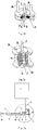
- a colorant pump capable of dispensing both a large volume and a small volume of colorant disclosed in the present invention essentially consists of a volume-variable space I large pump body or large cylinder body 1, a large reciprocating part (comprising a large reciprocating lever 2, an energy applying end 2a of the large reciprocating lever 2, and a piston 2b driven by the large reciprocating lever 2), a volume-variable space II small pump body or small cylinder body 4, a small reciprocating part or small reciprocating lever 3, a large pump inlet-outlet opening 5 and a small pump inlet-outlet opening 6.
- the large cylinder body 1, the large reciprocating part and the large pump inlet-outlet opening 5 constitute a large reciprocating positive displacement pump; the small reciprocating part, the small pump body and the small pump inlet-outlet opening 6 constitute a small reciprocating positive displacement pump; and the small reciprocating positive displacement pump and the large reciprocating positive displacement pump operate simultaneously.
- a person skilled in the art may also implement the present invention using a plunger pump head instead of the large reciprocating lever 2 and the piston 2b. As shown in Fig.
- the volume of the colorant dispensed by the large reciprocating lever 2 in the large cylinder body 1 is divided into two fractions: one is the volume dispensed via the small pump inlet-outlet opening, and the other one is the volume dispensed via the large pump inlet-outlet opening; thus, under the circumstance of dispensing via the small pump inlet-outlet opening and returning to a canister via the large pump inlet-outlet opening, it is small volume dispensing; and for dispensing via both the small pump inlet-outlet opening and the large pump inlet-outlet opening, it is large volume dispensing.
- the small reciprocating lever 3 forms a pump for dispensing a small volume of colorant within the small cylinder body 4 to dispense a small volume of colorant via the small pump inlet-outlet opening 6, and in this case, the colorant in the large cylinder body 1 is expelled into the canister via the large pump inlet-outlet opening 5, thereby achieving dispensing of a small volume of colorant.
- the axis of the small cylinder body 4 is non-coaxial with that of the large cylinder body 1.
- Figs. 2a and 2b are diagrams of the volume-variable space I as a folding body 1a of a folding pump, wherein the folding body 1a is the large pump body.
- Fig. 2a shows the operating condition of the large pump when the small reciprocating lever 3 or small reciprocating part is not in the small pump body (i.e., the small cylinder body 4)
- Fig. 2b shows the operating condition of the small pump when the small reciprocating lever 3 is in the small cylinder body 4.
- the operating principle thereof is the same as that in Figs. 1a and 1b , i.e., the folding body 1a being equivalent to the large pump body 1, and the large reciprocating lever 2 and a large reciprocating plate 2c connected thereto constituting the large reciprocating part.
- Other parts include the small reciprocating part 3, the small pump body 4, the large pump inlet-outlet opening 5, the small pump inlet-outlet opening 6, and a guiding pillar 2d.
- This embodiment is also an embodiment where the small pump body 4 being non-coaxial with that of the folding body 1a.
- the large reciprocating positive displacement pump is a large folding pump.
- the large reciprocating lever 2 and the large reciprocating plate 2c connected thereto constitute the large reciprocating part;
- the large reciprocating lever 2 drives the large reciprocating plate 2c into reciprocating motion along the guiding pillar 2d;
- the large pump inlet-outlet opening 5 is provided in the base of the large folding pump body 1a;
- a small folding pump body 4a is nested in the large folding pump body 1a (i.e., large pump);
- the small pump inlet-outlet opening 6 is provided in the base of the small folding pump body 4a;
- the small reciprocating part is partial plate surface of the large reciprocating plate 2c that corresponds to the small folding pump body 4a.
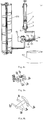
- Figs. 3a , 3b, 3c and 3d show an embodiment of a colorant pump capable of dispensing both a large volume and a small volume of colorant.
- Two three-way valves are used to control the large pump inlet-outlet opening 5 and the small pump inlet-outlet opening 6 to connect with a colorant dispensing outlet.
- the three-way valve is not limited to rotary valve, and may also be electromagnetic three-way valve, sliding bar three-way valve, sliding vane three-way valve, or the like.
- the two three-way valves may be used for individual control, and may also be connected to simultaneously control opening and closing of various channels. As shown in Fig.
- the large reciprocating lever 2, the energy applying end 2a of the large reciprocating lever 2 and the piston 2b driven by the large reciprocating lever 2 constitute the large reciprocating part, colorant circulating channels are provided between the small reciprocating part or small reciprocating lever 3, the large pump inlet-outlet opening 5, the small pump inlet-outlet opening 6, and a canister inlet-outlet opening 8 and a colorant dispensing outlet 9;
- the large pump inlet-outlet opening 5 connects with the first port of the three-way valve II 7b;
- the second port of the three-way valve II 7b connects with the canister inlet-outlet opening 8;
- the small pump inlet-outlet opening 6 connects with the first port of the three-way valve I 7a;
- the second port of the three-way valve I 7a connects with the colorant dispensing outlet 9;
- the third port of the three-way valve II 7b connects with the channel between the small pump inlet-outlet opening 6 and the three-way valve I 7a; and the third
- the large pump inlet-outlet opening 5 and the small pump inlet-outlet opening 6 both connect with the canister inlet-outlet opening 8, and then the objective of suction of colorant may be achieved by drawing the large reciprocating lever 2; the directions of the three-way valve I 7a and the three-way valve II 7b are adjusted to where Fig.
- 3b shows such that the large pump inlet-outlet opening 5 connects with the canister inlet-outlet opening 8 and the small pump inlet-outlet opening 6 connects with the colorant dispensing outlet 9, and then the objective of small volume dispensing by the small pump and returning from the large pump to the canister, i.e., dispensing of a small volume of colorant, may be achieved; the directions of the three-way valve I 7a and the three-way valve II 7b are adjusted to where Fig.
- 3c shows such that the large pump inlet-outlet opening 5 and the small pump inlet-outlet opening 6 both connect with the colorant dispensing outlet 9, and then the objective of simultaneous dispensing by the small pump and the large pump, i.e., large-dosage dispensing of colorant, may be achieved; and as shown in Fig. 3d , the large pump inlet-outlet opening 5 and the small pump inlet-outlet opening 6 both connect with the canister inlet-outlet opening 8, and then the objective of suction of colorant may be achieved as well.
- a colorant pump capable of dispensing both a large volume and a small volume of colorant is a piston pump comprising the large cylinder body 1 (i.e., the large pump body) and the large reciprocating level 2 which is a piston rod.
- the piston rod achieves suction or extrusion by means of the piston 2b, and the large reciprocating level 2 and the piston 2b constitute the large reciprocating part.
- the small reciprocating lever 3 extends from the piston 2b into the cylinder.
- a reciprocating pump constituted by the large cylinder body 1 and the large reciprocating part is referred to as the large pump.
- Another cylinder body is disposed in the base of the large cylinder body 1, referred to as the small cylinder body 4 (i.e., the small pump body).
- a hole may be directly bored in or a pipe may be disposed on the large cylinder body 1 to serve as the small cylinder body 4, and the large cylinder body 1 and the small cylinder body 4 are disposed coaxially, as shown in Fig. 4 ; the end, projecting into the cylinder, of the large reciprocating lever 2 is connected to another reciprocating lever which is referred to as the small reciprocating lever 3 (i.e., the small reciprocating part).
- the small cylinder body 4 may match with the small reciprocating lever 3 to constitute the small pump.
- the small cylinder body 4 is provided with the small pump inlet-outlet opening 6, and the large cylinder body 1 is provided with the large pump inlet-outlet opening 5.
- the length of the small reciprocating lever 3 projecting into the small cylinder body 4 is greater than or equal to the stroke of the large reciprocating lever 2, and in this case, the small reciprocating lever 3 is invariably in the small cylinder body 4. Also, the length of the small reciprocating lever 3 projecting into the small cylinder body 4 may be less than the stroke of the large reciprocating lever 2, as shown in Fig. 5 , and in this case, the small reciprocating lever 3 may be detached from the small cylinder body 4.
- Control valves may be provided for the large pump inlet-outlet opening 5 and the small pump inlet-outlet opening 6 to control connection thereof with a canister or to control dispensing therethrough.
- Figs. 4 and 5 show an embodiment where the small cylinder body 4 and the large cylinder body 1 are disposed coaxially, thus allowing easier manufacturing and implementation.
- the small pump body being disposed on the base of the large pump body means that the small pump body extends from the surface of the base of the large pump body, and in this case, the small cylinder body 4 protrudes from the surface 110 of the base of the large cylinder body 1, as shown in Fig. 6 .
- control valves may be rotary valves, sliding valves, or stop valves in other form that may achieve the above-mentioned functions.
- a driving slider I 52 is disposed in front of a stepper motor 51; a fixed slider II 53 is disposed below the driving slider I 52; the driving slider I 52 is provided with an elongated large pump inlet-outlet opening 5a and an elongated small pump inlet-outlet opening 6a that connect with the large pump inlet-outlet opening 5 and the small pump inlet-outlet opening 6, and a canister inlet-outlet opening is branched into a canister inlet-outlet opening I 8a and a canister inlet-outlet opening II 8b.
- the canister inlet-outlet opening I 8a and the canister inlet-outlet opening II 8b connect with the large pump inlet-outlet opening 5 and the small pump inlet-outlet opening 6 respectively, and then the objective of suction of colorant may be achieved by drawing the large reciprocating lever 2.
- the large pump inlet-outlet opening 5 connects with the canister inlet-outlet opening I 8a, and the elongated small pump inlet-outlet opening 6a is exposed as a dispensing outlet, and then the objective of the small pump operating, i.e., small-dosage dispensing of colorant, may be achieved.
- the small pump operating i.e., small-dosage dispensing of colorant
- the stepper motor 51 may drive the slider to move, thereby realizing different pipe connection modes as described above and achieving different objectives.
- a small pump is disposed within a large pump
- the small pump when the small pump operates, if the small pump has a small diameter, the small pump is used for small volume dispensing, and if the small pump has a large diameter, a small volume will be dispensed via the elongated large pump inlet-outlet opening 5a.
- the small pump as shown in Fig. 8a, Fig. 8b and Fig. 8c has a large diameter, and then a small volume will be dispensed via the elongated large pump inlet-outlet opening 5a due to small residual area of the large pump instead of the elongated small pump inlet-outlet opening 6a.
- Fig. 8a corresponds to that in Fig. 7a
- the connecting mode in Fig. 8c corresponds to that in Fig. 7c
- the elongated large pump inlet-outlet opening 5a in Fig. 8b is used for direct dispensing
- the elongated small pump inlet-outlet opening 6a connects with a canister.
- the two modes as described above are merely illustrative of the relativity of large and small pumps, and it is generally subject to that the small pump having a smaller diameter dispenses a small volume of colorant.
- two canister inlet-outlet openings 8a, 8b are directly driven by a motor to be directly aligned to the large pump inlet-outlet opening 5 and the small pump inlet-outlet opening 6, and the same objectives may also be achieved by sliding the two canister inlet-outlet openings 8a, 8b.
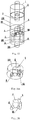
- each control valve comprises a valve body and a valve core, as shown in Figs. 10a and 10b.
- Fig. 10b is a diagram of internal colorant channels of a valve body shown in Fig. 10a .
- the valve body is provided with a large pump inlet-outlet opening 5 and a small pump inlet-outlet opening 6, a canister inlet-outlet opening 8 and a colorant dispensing outlet 9.
- the valve body may be connected to a folding pump, a piston pump or a plunger pump as described above.
- the colorant dispensing outlet 9 may be a window or a notch in the lower end face of the valve body, and may also be a channel, wherein the canister inlet-outlet opening 8 connects with a branch canister inlet-outlet opening I 8a by means of a first branch channel 8y and with a branch canister inlet-outlet opening II 8b by means of a second branch channel 8x.
- the valve core is provided with an axial channel 7e, and a radial channel I 7b, a radial channel II 7c, and a radial channel III 7d connect with the axial channel 7e respectively; the valve core is provided in the surface thereof with an arc groove channel 7a.
- the arc groove channel 7a is aimed at realizing colorant channels at two positions of the surface of the valve core.
- the channel is not limited to the arc groove channel; for example, a through hole is directly bored in the surface to achieve penetration of two positions of the surface.
- the radial channel I 7b and the arc groove channel 7a correspond to the large pump inlet-outlet opening 5, and the axial channel 7e invariably connects with the small pump inlet-outlet opening 6.
- Fig. 11a shows a diagram of colorant channels within the rotary valve.
- the arc groove 7a connects with the canister inlet-outlet opening I 8a; that is, the colorant from the large pump inlet-outlet opening returns to a canister through the arc groove 7a, the canister inlet-outlet opening I 8a and the first branch channel 8y;
- the small pump inlet-outlet opening 6 connects with the axial channel 7e
- the axial channel 7e connects with the radial channel II 7c that dispenses a small volume of colorant via the colorant dispensing outlet 9 with other channels being closed.
- the radial channel III 7d when the radial channel III 7d is aligned to the colorant dispensing outlet 9, the radial channel I 7b connects with the large pump inlet-outlet opening 5; that is, the large pump inlet-outlet opening 5 and the small pump inlet-outlet opening 6 both connect with the radial channel III 7d by means of the axial channel 7e, and the radial channel III 7d dispenses a large volume of colorant with other channels being closed.
- the radial channel I 7b connects with the branch canister inlet-outlet opening I 8a
- the large pump inlet-outlet opening 5 connects with the canister inlet-outlet opening 8 by means of the arc groove channel 7a, the branch canister inlet-outlet opening II 8b and the second branch channel 8x
- the small pump inlet-outlet opening 6 also connects with the canister inlet-outlet opening 8 by means of the axial channel 7e, the radial channel I 7b, the branch canister inlet-outlet opening I 8a and the first branch channel 8y for suction of colorant, based on an assumption of no branch canister inlet-outlet opening III 8c and branch canister inlet-outlet opening IV 8d being present.
- the canister inlet-outlet opening 8 is branched into the canister inlet-outlet opening I 8a and the canister inlet-outlet opening III 8b, both of which are located at sides of the valve core, and further branched into a branch canister inlet-outlet opening III 8c and a branch canister inlet-outlet opening IV 8d, both of which are located at sides of the valve core;
- the branch canister inlet-outlet opening III 8c and the branch canister inlet-outlet opening IV 8d correspond to the radial channel II 7c and the radial channel III 7d one to one;
- Figs. 12a, 12b , 13a and 13b show diagrams of another structure of a control valve which is a rotary valve.
- the control valve comprises a valve body II and a valve core II.
- the valve body II is provided with a large pump inlet-outlet opening 5, a small pump inlet-outlet opening 6, a canister inlet-outlet opening 8 and a colorant dispensing outlet 9, wherein the canister inlet-outlet opening 8 connects with a branch canister inlet-outlet opening I 8a by means of a first branch channel 8y and with a branch canister inlet-outlet opening II 8b by means of a second branch channel 8x, and is provided with a third branch channel 8z;
- the valve core II is provided with an axial channel 7f; a radial channel I 7b, a radial channel II 7c and a radial channel III 7d connect with the axial channel 7f respectively;
- the valve core II is provided in the surface thereof with an arc
- the canister inlet-outlet opening 8 is branched into the canister inlet-outlet opening I 8a and the canister inlet-outlet opening II 8b, both of which are located at sides of the valve core, and further branched into a canister inlet-outlet opening III 8c and a canister inlet-outlet opening IV 8d, both of which are located at sides of the valve core; the canister inlet-outlet opening III 8c and the canister inlet-outlet opening IV 8d correspond to the radial channel II 7c and the radial channel III 7d;
- Fig. 15 is a diagram of a control valve with another structure.
- a base 102 of a large cylinder body 1 is provided with a dispensing outlet 9 and a canister channel 8;
- a rotating shaft 103 is disposed in the axis of the base 102; and
- a rotary valve core IV 101 is disposed in the large cylinder body 1.
- Figs. 15 , 16a and 16b a base 102 of a large cylinder body 1 is provided with a dispensing outlet 9 and a canister channel 8;
- a rotating shaft 103 is disposed in the axis of the base 102; and a rotary valve core IV 101 is disposed in the large cylinder body 1.
- Figs. 15 is a diagram of a control valve with another structure.
- a base 102 of a large cylinder body 1 is provided with a dispensing outlet 9 and a canister channel 8;
- a rotating shaft 103 is disposed in the axis of the base 102;
- a small cylinder body 4 is disposed in the axis of the rotary valve core IV 101, and a small pump inlet-outlet opening 6 radially projects out of the small cylinder body 4; a large pump inlet-outlet opening 5 is provided outside the small cylinder body 4, and another inlet-outlet opening projects out of the small cylinder body 4, and connects with another inlet-outlet opening of the large pump to form a combined inlet-outlet opening 56.
- the valve core 101 is rotated such that:
- a reciprocating positive displacement pump may also be composed of one large pump and two or three small pumps.
- the reciprocating positive displacement pump may also be of an upside-down structure, as shown in Fig. 18 .
- the upside-down structure is conducive to air removal and improvement of the stability of the colorant dispensing accuracy.
- Driving for the large reciprocating part in the present invention includes manual driving, stepper motor driving, and servo motor driving.
- Position changeover of the control valves in the present invention includes changeover achieved manually, or by a stepper motor, a synchronous motor or a slowdown motor with position changeover control. By changing the directions and positions of the control valves, the objectives of suction of colorant, dispensing of a small volume of colorant, dispensing of a large volume of colorant, air removal and pump cleaning may be achieved. and the accuracy and efficiency of colorant dispensing are guaranteed.
- the pump capable of dispensing both a large volume and a small volume of colorant in the present invention conveniently achieves the objective of dispensing both a large volume and a small volume of colorant by simply rotating the control valves or pushing the sliding valves.
- the large reciprocating lever and the small reciprocating rod are formed into an integrated body, the problems that the accuracy is influenced by the telescoping force of a spring and a strict requirement is made to the leakproofness in the structure of patent US2009236367 is avoided.
Landscapes
- Engineering & Computer Science (AREA)
- General Engineering & Computer Science (AREA)
- Mechanical Engineering (AREA)
- Chemical & Material Sciences (AREA)
- Chemical Kinetics & Catalysis (AREA)
- Details Of Reciprocating Pumps (AREA)
- Multiple-Way Valves (AREA)
- Reciprocating Pumps (AREA)
- Sliding Valves (AREA)
- Coating Apparatus (AREA)
- Treatment Of Fiber Materials (AREA)
- Lift Valve (AREA)
- Cosmetics (AREA)
- Containers And Packaging Bodies Having A Special Means To Remove Contents (AREA)
Claims (13)
- Pumpe, die in der Lage ist, sowohl ein großes Volumen als auch ein kleines Volumen eines Färbemittels abzugeben, mit einer großen hin- und hergehenden Verdrängerpumpe, die ein großes hin- und hergehendes Teil, einen großen Pumpenkörper (1) und eine große Pumpen-Einlass/Auslass-Öffnung (5) aufweist, wobei ein kleines hin- und hergehendes Teil an dem großen hin- und hergehenden Teil befestigt und in dem großen Pumpenkörper (1) angeordnet ist, ein kleiner Pumpenkörper (4) an einer Basis des großen Pumpenkörpers (1) angeordnet und mit einer kleinen Pumpen-Einlass/Auslass-Öffnung (6) versehen ist, und das kleine hin- und hergehende Teil, der kleine Pumpenkörper und die Einlass/Auslass-Öffnung der kleinen Pumpe eine kleine hin- und hergehende Verdrängerpumpe bilden, wobei Steuerventile angeordnet sind, um die große Pumpen-Einlass/Auslass-Öffnung (5) und die kleine Pumpen-Einlass/Auslass-Öffnung (6) zu steuern, um eine Verbindung mit einem Kanister herzustellen oder um Farbmittel abzugeben, und wobei die Pumpe dadurch gekennzeichnet ist, dass die große Pumpen-Einlass/Auslass-Öffnung und die kleine Pumpen-Einlass/Auslass-Öffnung durch die Steuerventile gesteuert werden, um eine Verbindung mit einem Kanister herzustellen oder Farbmittel abzugeben, wobei mindestens die folgenden drei Verbindungsstrukturen beteiligt sind:① die große Pumpen-Einlass/Auslass-Öffnung (5) ist mit dem Kanister verbunden, oder die kleine Pumpen-Einlass/Auslass-Öffnung (6) ist mit dem Kanister verbunden, oder die große Pumpen-Einlass/Auslass-Öffnung (5) und die kleine Pumpen-Einlass/Auslass-Öffnung (6) sind beide mit dem Kanister verbunden, wobei die vorgenannten drei Anschlussmöglichkeiten für eine einzelne oder kombinierte Verwendung sind,② wenn die Abgabe nur über die große Pumpen-Einlass/Auslass-Öffnung (5) erfolgt, die große Pumpen-Einlass/Auslass-Öffnung (5) mit einem Farbmittelabgabeauslass zur Abgabe verbunden ist, oder wenn die Abgabe sowohl über die große Pumpen-Einlass/Auslass-Öffnung (5) als auch über die kleine Pumpen-Einlass/Auslass-Öffnung (6) zulässig ist, die große Pumpen-Einlass/Auslass-Öffnung (5) und die kleine Pumpe-Einlass/Auslass-Öffnung (6) beide mit dem Farbmittelabgabeauslass zur Abgabe verbunden sind, und③ wenn die Abgabe nur über die kleine Pumpen-Einlass/Auslass-Öffnung (6) erlaubt ist, die kleine Pumpen-Einlass/Auslass-Öffnung (6) mit dem Farbmittelabgabeauslass zur Abgabe verbunden ist.
- Pumpe, die in der Lage ist, sowohl ein großes Volumen als auch ein kleines Volumen an Farbmittel abzugeben, nach Anspruch 1, dadurch gekennzeichnet, dass "der kleine Pumpenkörper (4) ist an der Basis des großen Pumpenkörpers (1) angeordnet" bedeutet, dass der kleine Pumpenkörper (4) innerhalb der Basis des großen Pumpenkörpers (1) angeordnet ist.
- Pumpe, die in der Lage ist, sowohl ein großes Volumen als auch ein kleines Volumen an Farbmittel abzugeben, nach Anspruch 1, dadurch gekennzeichnet, dass "der kleine Pumpenkörper (4) ist an der Basis des großen Pumpenkörpers (1) angeordnet" bedeutet, dass sich der kleine Pumpenkörper (4) von einer Oberfläche der Basis des großen Pumpenkörpers (1) erstreckt.
- Pumpe, die in der Lage ist, sowohl ein großes Volumen als auch ein kleines Volumen an Farbmittel abzugeben, nach einem der vorhergehenden Ansprüche, dadurch gekennzeichnet, dass die große mit hin- und hergehende Verdrängerpumpe eine große Faltpumpe, eine große Plungerpumpe oder eine große Kolbenpumpe ist, und die kleine hin- und hergehende Verdrängerpumpe eine kleine Faltpumpe ist.
- Pumpe, die in der Lage ist, sowohl ein großes Volumen als auch ein kleines Volumen eines Farbmittels abzugeben, nach einem der Ansprüche 1 bis 3, dadurch gekennzeichnet, dass die große hin- und hergehende Verdrängerpumpe eine große Faltpumpe, eine große Plungerpumpe oder eine große Kolbenpumpe ist, und die kleine hin- und hergehende Verdrängerpumpe eine kleine Plungerpumpe oder eine kleine Kolbenpumpe ist, deren kleine Kolbenstange oder kleine Plungerstange in einen kleinen Zylinderkörper mit einer Länge ragt, die größer oder gleich dem Hub eines großen hin- und hergehenden Teils ist.
- Pumpe, die in der Lage ist, sowohl ein großes Volumen als auch ein kleines Volumen an Farbmittel abzugeben, nach einem der Ansprüche 1 bis 3, dadurch gekennzeichnet, dass die große hin- und hergehende Verdrängerpumpe eine große Faltpumpe, eine große Plungerpumpe oder eine große Kolbenpumpe ist, und das kleine hin- und hergehende Teil eine kleine Kolbenbaugruppe oder eine kleine Plungerstange ist, der kleine Pumpenkörper ein kleiner Zylinderkörper ist, eine maximale Länge der kleinen Kolbenbaugruppe oder der kleinen Plungerstange, die in den kleinen Zylinderkörper hineinragt, kleiner ist als der Hub des großen hin- und hergehenden Teils, und wenn die kleine Kolbenbaugruppe oder die kleine Kolbenstange in den kleinen Zylinderkörper hineinragt, die kleine Kolbenbaugruppe oder die kleine Kolbenstange, der kleine Zylinderkörper und die Einlass/Auslass-Öffnung der kleinen Pumpe eine kleine Plungerpumpe oder eine kleine Kolbenpumpe bilden.
- Pumpe, die in der Lage ist, sowohl ein großes Volumen als auch ein kleines Volumen an Farbmittel abzugeben, nach Anspruch 5 oder 6, dadurch gekennzeichnet, dass der kleine Pumpenkörper und der große Pumpenkörper koaxial angeordnet sind.
- Pumpe, die in der Lage ist, sowohl ein großes Volumen als auch ein kleines Volumen an Farbmittel abzugeben, nach einem der vorhergehenden Ansprüche, dadurch gekennzeichnet, dass das Steuerventil ein Schieberventil ist, bei dem ein Antriebsschieber I (52) mit einer langgestreckten großen Pumpen-Einlass/Auslass-Öffnung (5a) und einer langgestreckten kleinen Pumpen-Einlass/Auslass-Öffnung (6a) versehen ist, die mit einer großen Pumpen-Einlass/Auslass-Öffnung (5) und einer kleinen Pumpen-Einlass/Auslass-Öffnung (6) verbunden sind, und eine Kanister-Einlass/Auslass-Öffnung in eine Kanister-Einlass/Auslass-Öffnung I (8a) und eine Kanister-Einlass/Auslass-Öffnung II (8b) verzweigt ist:① die Kanister-Einlass/Auslass-Öffnung I (8a) und die Kanister-Einlass/Auslass-Öffnung II (8b) sind mit der großen Pumpen-Einlass/Auslass-Öffnung (5) bzw. der kleinen Pumpen-Einlass/Auslass-Öffnung (6) verbunden,② die langgestreckte große Pumpen-Einlass/Auslass-Öffnung (5a) und die langgestreckte kleine Pumpen-Einlass/Auslass-Öffnung (6a) sind beide exponiert, und③ die große Pumpen-Einlass/Auslass-Öffnung (5) ist mit der Kanister-Einlass/Auslass-Öffnung I (8a) verbunden und die langgestreckte kleine Pumpen-Einlass/Auslass-Öffnung (6a) ist exponiert, um als Dosierauslass zu dienen.
- Pumpe, die in der Lage ist, sowohl ein großes Volumen als auch ein kleines Volumen an Farbmittel abzugeben, nach einem der Ansprüche 1 bis 7, dadurch gekennzeichnet, dass: das Steuerventil einen Ventilkörper und einen Ventileinsatz aufweist, der Ventilkörper mit einer großen Pumpen-Einlass/Auslass-Öffnung (5), einer kleinen Pumpen-Einlass/Auslass-Öffnung (6), einer Kanister-Einlass/Auslass-Öffnung (8) und einem Farbmittelabgabe-Auslass (9) versehen ist, wobei die Kanister-Einlass/Auslass-Öffnung (8) mit der Zweigkanister-Einlass/Auslass-Öffnung I (8a) mittels eines ersten Zweigkanals (8y) und mit der Zweigkanister-Einlass/Auslass-Öffnung II (8b) mittels eines zweiten Zweigkanals (8x) verbunden ist, der Ventileinsatz mit einem axialen Kanal (7e) versehen ist, ein radialer Kanal I (7b), ein radialer Kanal II (7c) und ein radialer Kanal III (7d) jeweils mit dem axialen Kanal (7e) verbunden sind, der Ventileinsatz in einer Oberfläche desselben mit einem bogenförmigen Nutkanal (7a) versehen ist, der bogenförmige Nutkanal (7a) und der radiale Kanal I (7b) mit der großen Pumpen-Einlass/Auslass-Öffnung (5) korrespondieren, und der axiale Kanal (7e) unveränderlich mit der kleinen Pumpen-Einlass/Auslass-Öffnung (6) verbunden ist:① wenn der radiale Kanal I (7b) mit der Zweigkanister-Einlass/Auslass-Öffnung II (8b) verbunden ist, ist der radiale Kanal I (7b) mit einem Kanister zum Ansaugen von Farbmittel verbunden ist, und wenn der radiale Kanal I (7b) mit der Zweigkanister-Kanal-Einlass/Auslass-Öffnung I (8a) verbunden ist, sind der bogenförmige Nutkanal (7a) und der radiale Kanal I (7b) beide mit der Kanister-Kanal-Einlass/Auslass-Öffnung (8) zum Ansaugen von Farbmittel verbunden,② wenn der radiale Kanal III (7d) auf den Farbmittelabgabe-Auslass (9) ausgerichtet ist, ist der radiale Kanal I (7b) mit der großen Pumpen-Einlass/Auslass-Öffnung (5) verbunden, das heißt, die große Pumpen-Einlass/Auslass-Öffnung (5) und die kleine Pumpen-Einlass/Auslass-Öffnung (6) sind beide mit dem radialen Kanal III (7d) mittels des axialen Kanals (7e) verbunden, und der radiale Kanal III (7d) gibt ein großes Volumen an Farbmittel ab, wobei andere Kanäle geschlossen sind, und③ wenn der radiale Kanal II (7c) auf den Farbmittelabgabe-Auslass (9) ausgerichtet ist, ist der bogenförmige Nutkanal (7a) mit der Kanister-Einlass/Auslass-Öffnung I (8a) verbunden, d.h. ein Farbmittel aus der großen Pumpen-Einlass/Auslass-Öffnung (5) fließt zurück, die kleine Pumpen Einlass/Auslass-Öffnung (6) ist mit dem axialen Kanal (7e) verbunden, der mit dem radialen Kanal II (7c) verbunden, und der radiale Kanal II (7c) gibt ein kleines Volumen an Farbmittel mittels des Farbmittelabgabe-Auslasses (9) ab, wobei andere Kanäle geschlossen sind.
- Pumpe, die in der Lage ist, sowohl ein großes Volumen als auch ein kleines Volumen an Farbmittel abzugeben, nach Anspruch 9, dadurch gekennzeichnet, dass die Kanister-Einlass/Auslass-Öffnung (8) in die Kanister-Einlass/Auslass-Öffnung I (8a) und die Kanister-Einlass/Auslass-Öffnung II (8b) verzweigt ist, die sich beide an Seiten des Ventilkerns befinden, und weiter in eine Kanister-Einlass/Auslass-Öffnung III (8c) und eine Kanister-Einlass/Auslass-Öffnung IV (8d) verzweigt ist, die sich beide an Seiten des Ventilkerns befinden, und die Kanister-Einlass/Auslass-Öffnung III (8c) und die Kanister-Einlass/Auslass-Öffnung IV (8d) korrespondieren mit dem radialen Kanal II (7c) und dem radialen Kanal III (7d),① wenn der radiale Kanal I (7b) mit der Kanister-Kanal-Einlass/Auslass-Öffnung II (8b) verbunden ist, sind der radiale Kanal III (7d) mit der Zweigkanister-Einlass/Auslass-Öffnung III (8c) und der radiale Kanal II (7c) mit der Zweigkanister-Einlass/Auslass-Öffnung IV (8d) verbunden, und die kleine Pumpen-Einlass/Auslass-Öffnung (6) ist mit einem Kanister zum Ansaugen von Farbmittel verbunden, und② wenn der radiale Kanal I (7b) mit der Einlass/Auslass-Öffnung I (8a) des Kanisterkanals verbunden ist, ist der radiale Kanal III (7d) mit der Zweigkanister-Einlass/Auslass-Öffnung IV (8d) und der radiale Kanal II (7c) mit der Zweigkanister-Einlass/Auslass-Öffnung III (8c) verbunden ist, und die große Pumpen-Einlass/Auslass-Öffnung (5) und die kleine Pumpen-Einlass/Auslass-Öffnung (6) mit einem Kanister zum Ansaugen von Farbmittel verbunden sind.
- Pumpe, die in der Lage ist, sowohl ein großes Volumen als auch ein kleines Volumen an Farbmittel abzugeben, nach einem der Ansprüche 1 bis 7, dadurch gekennzeichnet, dass: das Steuerventil einen Ventilkörper II und einen Ventileinsatz II aufweist, der Ventilkörper II mit einer großen Pumpe-Einlass/Auslass-Öffnung (5), einer kleinen Pumpen-Einlass/Auslass-Öffnung (6), einer Kanister-Einlass/Auslass-Öffnung (8) und einem Farbmittelabgabe-Auslass (9) versehen ist, wobei die Kanister-Einlass/Auslass-Öffnung (8) über einen ersten Abzweigkanal (8y) mit einer Zweigkanister-Einlass/Auslass-Öffnung I (8a) und über einen zweiten Abzweigkanal (8x) mit einer Zweigkanister-Einlass/Auslass-Öffnung II (8b) verbunden ist und mit einem dritten Abzweigkanal (8z) versehen ist, der Ventileinsatz II mit einem axialen Kanal (7f) versehen ist, ein radialer Kanal I (7b), ein radialer Kanal II (7c) und ein radialer Kanal III (7d) jeweils mit dem axialen Kanal (7f) verbunden sind, der Ventileinsatz II in einer seiner Oberflächen mit einem bogenförmigen Nutkanal (7a) versehen ist, der bogenförmige Nutkanal (7a) und der radiale Kanal I (7b) mit der großen Pumpen-Einlass-Auslass-Öffnung (5) korrespondieren, und ein kleiner radialer Pumpen-Kanal I (7i), ein kleiner radialer Pumpen-Kanal II (7j), ein kleiner radialer Pumpen-Kanal III (7k) und ein kleiner axialer Pumpen-Kanal (7h) axial um 90° beabstandet auf dem Teil des axialen Kanals (7f) angeordnet sind, der mit der kleinen Pumpen-Einlass/Auslass-Öffnung (6) korrespondiert:① wenn der radiale Kanal I (7b) mit der Zweigkanister-Einlass/Auslass-Öffnung II (8b) verbunden ist, ist der radiale Kanal I (7b) verbunden, und die große Pumpen-Einlass/Auslass-Öffnung (5) ist mit dem bogenförmigen Nutkanal (7a) und der Zweigkanister-Kanal-Einlass/Auslass-Öffnung I (8a) verbunden, und die kleine Pumpen-Einlass/Auslass-Öffnung (6) ist mit der Kanister-Einlass/Auslass-Öffnung (8) mittels des axialen kleinen Pumpenkanals (7h) zum Ansaugen von Farbmittel verbunden, wobei andere Kanäle geschlossen sind,② wenn der radiale Kanal III (7d) auf den Farbmittelabgabe-Auslass (9) ausgerichtet ist, sind die große Pumpen-Einlass/Auslass-Öffnung (5) mit dem axialen Kanal (7f) über den radialen Kanal I (7b) und die kleine Pumpen-Einlass/Auslass-Öffnung (6) mit dem axialen Kanal (7f) über den radialen kleinen Pumpenkanal III (7k) verbunden, das heißt, die große Pumpe-Einlass-Auslass-Öffnung (5) und die kleine Pumpen-Einlass/Auslass-Öffnung (6) sind beide mit dem radialen Kanal III (7d) mittels des axialen Kanals (7f) verbunden, und der radiale Kanal III (7d) gibt ein großes Volumen an Farbmittel ab, wobei andere Kanäle geschlossen sind, und③ wenn der radiale Kanal II (7c) auf den Farbmittelabgabe-Auslass (9) ausgerichtet ist, ist der bogenförmige Nutkanal (7a) mit der Kanister-Einlass/Auslass-Öffnung II (8b) verbunden, d.h. es fließt Farbmittel aus der großen Pumpen-Einlass/Auslass-Öffnung (5) zurück, die kleine Pumpen-Einlass/Auslass-Öffnung (6) ist mit dem axialen Kanal (7f) mittels des radialen kleinen Pumpenkanals I (7i) verbunden, der axiale Kanal (7f) ist mit dem radialen Kanal II (7c), der ein kleines Volumen an Farbmittel über den Farbmittelabgabe-Auslass (9) abgibt, verbunden wobei andere Kanäle geschlossen sind.
- Pumpe, die in der Lage ist, sowohl ein großes Volumen als auch ein kleines Volumen an Farbmittel abzugeben, nach Anspruch 11, dadurch gekennzeichnet, dass die Kanister-Einlass/Auslass-Öffnung (8) in die Kanister-Einlass/Auslass-Öffnung I (8a) und die Kanister-Einlass/Auslass-Öffnung II (8b) verzweigt ist, die sich beide an Seiten des Ventilkerns befinden, und weiter in eine Kanister-Einlass/Auslass-Öffnung III (8c) und eine Kanister-Einlass/Auslass-Öffnung IV (8d) verzweigt ist, die sich beide an Seiten des Ventilkerns befinden, die Kanister-Einlass/Auslass-Öffnung III (8c) und die Kanister-Einlass/Auslass-Öffnung IV (8d) korrespondieren mit dem radialen Kanal II (7c) und dem radialen Kanal III (7d),① wenn der radiale Kanal I (7b) mit der Kanister-Kanal-Einlass/Auslass-Öffnung II (8b) verbunden ist, ist der radiale Kanal III (7d) mit der Zweigkanister-Einlass/Auslass-Öffnung III (8c) verbunden und der radiale Kanal II (7c) ist mit der Kanister-Einlass/Auslass-Öffnung IV (8d) verbunden, und② wenn der radiale Kanal I (7b) mit der Einlass/Auslass-Öffnung I (8a) des Kanisters verbunden ist, ist der radiale Kanal II (7c) mit der Zweigkanister-Einlass/Auslass-Öffnung III (8c) verbunden und der radiale Kanal III (7c) ist mit der Kanister-Einlass/Auslass-Öffnung IV (8d) verbunden.
- Pumpe, die in der Lage ist, sowohl ein großes Volumen als auch ein kleines Volumen an Farbmittel abzugeben, nach einem der Ansprüche 1 bis 7, dadurch gekennzeichnet, dass: im Steuerventil in einem Boden eines großen Zylinderkörpers (1) ein Abgabeauslass (9) und ein Kanisterkanal (8) vorgesehen sind, im großen Zylinderkörper (1) ein Drehventilkern IV angeordnet ist, in der Achse des Drehventilkerns IV ein kleiner Zylinderkörper (4) angeordnet ist, und aus dem kleinen Zylinderkörper (4) eine kleine Pumpen-Einlass/Auslass-Öffnung (6) radial herausragt, eine große Pumpen-Einlass/Auslass-Öffnung (5), die außerhalb des kleinen Zylinderkörpers (4) vorgesehen ist, und eine weitere Einlass/Auslass-Öffnung aus dem kleinen Zylinderkörper (4) herausragt und mit einer weiteren großen Pumpen-Einlass/Auslass-Öffnung verbunden ist, um eine kombinierte Einlass/Auslass-Öffnung (56) zu bilden,① die kombinierte Einlass/Auslass-Öffnung (56) ist auf den Kanisterkanal (8) zum Ansaugen von Farbmittel ausgerichtet,② die große Pumpen-Einlass-Auslass-Öffnung (5) oder die kombinierte Einlass/Auslass-Öffnung (56) auf den Abgabeauslass (9) sind ausgerichtet, um ein großes Volumen an Farbmittel abzugeben, und③ die kleine Pumpen-Einlass/Auslass-Öffnung (6) ist auf den Abgabeauslass (9) ausgerichtet, um ein kleines Volumen an Farbmittel abzugeben.
Applications Claiming Priority (4)
| Application Number | Priority Date | Filing Date | Title |
|---|---|---|---|
| CN201410792472.5A CN105757022B (zh) | 2014-12-19 | 2014-12-19 | 既大量注出又微量注出色浆的控制阀 |
| CN201410792555.4A CN105756919B (zh) | 2014-12-19 | 2014-12-19 | 一种既大量注出又微量注出色浆泵 |
| CN201410792479.7A CN105757023B (zh) | 2014-12-19 | 2014-12-19 | 一种既大量注出又微量注出色浆的控制阀 |
| PCT/CN2015/097973 WO2016095865A1 (zh) | 2014-12-19 | 2015-12-18 | 一种既大量注出又微量注出色浆泵 |
Publications (3)
| Publication Number | Publication Date |
|---|---|
| EP3249222A1 EP3249222A1 (de) | 2017-11-29 |
| EP3249222A4 EP3249222A4 (de) | 2018-08-01 |
| EP3249222B1 true EP3249222B1 (de) | 2021-04-14 |
Family
ID=56125962
Family Applications (2)
| Application Number | Title | Priority Date | Filing Date |
|---|---|---|---|
| EP15869373.9A Active EP3236120B1 (de) | 2014-12-19 | 2015-12-18 | Steuerventil zum giessen einer farbpaste in sowohl grossen mengen als auch kleinen mengen |
| EP15869372.1A Active EP3249222B1 (de) | 2014-12-19 | 2015-12-18 | Farbpastenpumpe für massive injektion und mikroinjektion |
Family Applications Before (1)
| Application Number | Title | Priority Date | Filing Date |
|---|---|---|---|
| EP15869373.9A Active EP3236120B1 (de) | 2014-12-19 | 2015-12-18 | Steuerventil zum giessen einer farbpaste in sowohl grossen mengen als auch kleinen mengen |
Country Status (10)
| Country | Link |
|---|---|
| US (2) | US10221839B2 (de) |
| EP (2) | EP3236120B1 (de) |
| JP (2) | JP6557339B2 (de) |
| KR (2) | KR102003477B1 (de) |
| BR (1) | BR112017013218B1 (de) |
| ES (2) | ES2879965T3 (de) |
| MX (2) | MX383616B (de) |
| MY (2) | MY189461A (de) |
| RU (2) | RU2683008C2 (de) |
| WO (2) | WO2016095865A1 (de) |
Families Citing this family (15)
| Publication number | Priority date | Publication date | Assignee | Title |
|---|---|---|---|---|
| MY189461A (en) * | 2014-12-19 | 2022-02-15 | Zhengzhou Sanhua Tech & Industry Co Ltd | Pump capable of dispensing both a large volume and a small volume of colorant |
| CN106145016B (zh) * | 2016-08-27 | 2019-08-06 | 吴朝辉 | 一种调色机活塞式定量输料器 |
| CN107781129B (zh) * | 2016-08-30 | 2019-07-05 | 郑州三华科技实业有限公司 | 三级变量色浆泵及其操作方法 |
| CN108194299B (zh) * | 2017-12-22 | 2020-02-11 | 郑州三华科技实业有限公司 | 大泵强回流大泵单注出复合泵阀 |
| CN108194303B (zh) * | 2017-12-22 | 2020-02-11 | 郑州三华科技实业有限公司 | 小泵强回流大泵单注出复合泵阀 |
| CN108194301B (zh) * | 2017-12-22 | 2020-02-11 | 郑州三华科技实业有限公司 | 小泵强回流大泵注小量复合泵 |
| WO2019120306A1 (zh) * | 2017-12-22 | 2019-06-27 | 郑州三华科技实业有限公司 | 复合泵阀 |
| CN108194300B (zh) * | 2017-12-22 | 2020-02-11 | 郑州三华科技实业有限公司 | 大小泵同时强回流及大小泵同时注出复合泵阀 |
| CN108194304B (zh) * | 2017-12-22 | 2020-02-11 | 郑州三华科技实业有限公司 | 大泵强回流小泵注小量复合泵 |
| CN108194302B (zh) * | 2017-12-22 | 2020-02-11 | 郑州三华科技实业有限公司 | 大泵前端强回流低阻复合泵阀 |
| EP3711867B1 (de) * | 2019-03-17 | 2023-09-06 | Zhengzhou Sanhua Technology & Industry Co., Ltd. | Ausgiessanordnung |
| EP3712432B1 (de) * | 2019-03-19 | 2024-07-17 | Fast & Fluid Management B.V. | Flüssigkeitsspender und verfahren zum betrieb solch eines spenders |
| CN111543844A (zh) * | 2020-05-21 | 2020-08-18 | 郑州三华科技实业有限公司 | 多功能烹饪装置 |
| WO2023170117A1 (en) | 2022-03-09 | 2023-09-14 | Fast & Fluid Management B.V. | Liquid dispenser |
| EP4609946A1 (de) | 2024-02-29 | 2025-09-03 | Fast & Fluid Management B.V. | Tönungsmaschine mit verdrängerpumpe |
Family Cites Families (32)
| Publication number | Priority date | Publication date | Assignee | Title |
|---|---|---|---|---|
| SU1378A1 (ru) * | 1924-06-27 | 1924-09-15 | С.М. Волох | Насос дл глубоких нефт ных скважин |
| US3851798A (en) * | 1972-11-10 | 1974-12-03 | Miller Mfg Co Of Schiller Park | Automatic colorant dispenser |
| US4060178A (en) * | 1974-05-10 | 1977-11-29 | Miller Mfg. Co. Of Schiller Park, Inc. | Metering pump |
| US4027785A (en) * | 1976-04-12 | 1977-06-07 | Chicago Commutator, Inc. | Dual pump colorant dispenser |
| DE2810761C3 (de) * | 1977-03-24 | 1980-05-22 | Maschinenfabrik Peter Zimmer Ag, Kufstein, Tirol (Oesterreich) | Spritzdüse |
| SU672371A1 (ru) * | 1977-11-15 | 1979-07-05 | Войсковая часть 90720 | Многокомпонентна дозирующа установка |
| JPS5674715A (en) * | 1979-11-21 | 1981-06-20 | Kurabo Ind Ltd | Liquid compounding equipment |
| US4759504A (en) | 1986-12-30 | 1988-07-26 | Weatherford U.S., Inc. | Dump control and valve |
| US5078302A (en) * | 1989-07-17 | 1992-01-07 | Fluid Management Limited Partnership | Paint dispensing apparatus |
| JP2519377Y2 (ja) * | 1990-08-20 | 1996-12-04 | 日東造機株式会社 | 液圧プランジャポンプにおけるプランジャ |
| JPH04106657U (ja) * | 1991-02-20 | 1992-09-14 | 本田技研工業株式会社 | 導電性塗料用切換弁 |
| CA2135190A1 (en) * | 1993-03-23 | 1994-09-29 | Leendert Hellenberg | Improved dispensing apparatus |
| US5540562A (en) * | 1994-04-28 | 1996-07-30 | Ashirus Technologies, Inc. | Single-piston, multi-mode fluid displacement pump |
| US6164499A (en) * | 1999-07-27 | 2000-12-26 | H.E.R.O. Industries A Division Of Middlefield Bancorp Limited | Paint colorant dispenser and valve therefor |
| DE10019283A1 (de) | 2000-04-19 | 2001-11-22 | Hella Kg Hueck & Co | Reinigungsanlage für Scheiben |
| US6726065B2 (en) * | 2002-02-04 | 2004-04-27 | Brian C. Sanders | Modular automatic colorant dispenser |
| US7311223B2 (en) * | 2004-05-07 | 2007-12-25 | Fluid Management, Inc. | Apparatus for dispensing a plurality of powders and method of compounding substances |
| US7644840B2 (en) * | 2005-02-04 | 2010-01-12 | Fluid Management Operations Llc | Valve assembly for viscous fluid dispensers |
| RU2294453C1 (ru) * | 2005-08-08 | 2007-02-27 | Общество с ограниченной ответственностью фирма "Саратовгазприборавтоматика" | Плунжерное дозирующее устройство |
| FR2896281B1 (fr) * | 2006-01-13 | 2008-02-29 | Dosatron International | Machine hydraulique, en particulier moteur hydraulique, a mouvement alternatif. |
| IT1376547B (it) * | 2006-10-04 | 2010-06-22 | Dromont S P A | Dispositivo automatico di dosaggio di fluidi, in particolare vernici o coloranti. |
| US8240513B2 (en) * | 2008-03-24 | 2012-08-14 | Fluid Management Operations Llc | Fluid dispenser with nested displacement members |
| CN100575701C (zh) * | 2008-04-30 | 2009-12-30 | 林波 | 计量泵及其驱动装置 |
| EP2116394B1 (de) | 2008-05-06 | 2012-05-02 | Cps Color Equipment Oy | Anordnung für die Ausgabe einer Farbpaste, Vorrichtung und Verfahren |
| CN201284727Y (zh) | 2008-10-17 | 2009-08-05 | 石钟哲 | 双级流量柱塞水泵及其组成的灭火系统 |
| CN201827040U (zh) | 2010-06-12 | 2011-05-11 | 德帕姆(杭州)泵业科技有限公司 | 一种并联式双缸计量泵 |
| US20120037666A1 (en) * | 2010-08-12 | 2012-02-16 | Fluid Management Operations, Llc | Anti-Drip Valve for Fluid Dispensers |
| CN201943911U (zh) | 2010-10-12 | 2011-08-24 | 肖桂连 | 电液比例定量泵 |
| RU2442020C1 (ru) * | 2010-11-30 | 2012-02-10 | Закрытое акционерное общество Научно-техническая компания "МОДУЛЬНЕФТЕГАЗКОМПЛЕКТ" | Дозатор подачи реагента в трубопровод |
| CN103968106B (zh) | 2013-02-05 | 2016-08-10 | 沈如华 | 调色机及其换向阀装置 |
| WO2014139135A1 (zh) * | 2013-03-15 | 2014-09-18 | 沈如华 | 流体调节装置 |
| MY189461A (en) * | 2014-12-19 | 2022-02-15 | Zhengzhou Sanhua Tech & Industry Co Ltd | Pump capable of dispensing both a large volume and a small volume of colorant |
-
2015
- 2015-12-18 MY MYPI2017702254A patent/MY189461A/en unknown
- 2015-12-18 KR KR1020177016960A patent/KR102003477B1/ko active Active
- 2015-12-18 US US15/537,797 patent/US10221839B2/en active Active
- 2015-12-18 RU RU2017125622A patent/RU2683008C2/ru active
- 2015-12-18 WO PCT/CN2015/097973 patent/WO2016095865A1/zh not_active Ceased
- 2015-12-18 MY MYPI2017702252A patent/MY189695A/en unknown
- 2015-12-18 EP EP15869373.9A patent/EP3236120B1/de active Active
- 2015-12-18 US US15/537,787 patent/US10533543B2/en active Active
- 2015-12-18 ES ES15869372T patent/ES2879965T3/es active Active
- 2015-12-18 JP JP2017526056A patent/JP6557339B2/ja active Active
- 2015-12-18 EP EP15869372.1A patent/EP3249222B1/de active Active
- 2015-12-18 MX MX2017008014A patent/MX383616B/es unknown
- 2015-12-18 JP JP2017526134A patent/JP6557340B2/ja active Active
- 2015-12-18 ES ES15869373T patent/ES2879971T3/es active Active
- 2015-12-18 BR BR112017013218-4A patent/BR112017013218B1/pt active IP Right Grant
- 2015-12-18 WO PCT/CN2015/097974 patent/WO2016095866A1/zh not_active Ceased
- 2015-12-18 RU RU2017125576A patent/RU2692169C2/ru active
- 2015-12-18 MX MX2017008020A patent/MX2017008020A/es unknown
- 2015-12-18 KR KR1020177016959A patent/KR102003476B1/ko active Active
Non-Patent Citations (1)
| Title |
|---|
| None * |
Also Published As
Similar Documents
| Publication | Publication Date | Title |
|---|---|---|
| US10533543B2 (en) | Pump capable of dispensing both a large volume and a small volume of colorant | |
| EP2974788A1 (de) | Flüssigkeitseinstellungsvorrichtung | |
| CN105756919A (zh) | 一种既大量注出又微量注出色浆泵 | |
| CN110454350B (zh) | 一种调色机的双级流量色浆供应装置 | |
| CN201521411U (zh) | 混凝土输送泵及其分配阀油缸换向机构 | |
| CN105757022B (zh) | 既大量注出又微量注出色浆的控制阀 | |
| CN210460971U (zh) | 一种调色机的双级流量色浆供应装置 | |
| CN110714905B (zh) | 一种手动变量蠕动泵 | |
| CN209306113U (zh) | 液体分配器 | |
| CN214366564U (zh) | 一种多通道切换的活塞泵 | |
| CN210033744U (zh) | 一种可拆卸式定量柱塞泵 | |
| CN208534746U (zh) | 一种应用螺杆泵的清桶装置 | |
| CN201661436U (zh) | 一种利用螺杆换向的气动泵 | |
| CN220378420U (zh) | 一种串联式柱塞泵 | |
| CN107811342A (zh) | 一种做服装用工作台 | |
| CN100587231C (zh) | 中空外旋转液压马达 | |
| CN221779762U (zh) | 一种插装式液控单向阀 | |
| CN216094457U (zh) | 高压聚氨酯喷涂机 | |
| CN214973747U (zh) | 一种玻璃胶加工的颜料定量输入系统 | |
| CN203018637U (zh) | 自动冲床的反转装置 | |
| CN223788742U (zh) | 一种可定量喷涂的喷涂设备 | |
| CN212383917U (zh) | 一种隔膜喷涂机 | |
| BR112017013215B1 (pt) | Bomba capaz de administrar um grande e um pequeno volume de pigmento | |
| US20130105011A1 (en) | Liquid-supply apparatus | |
| CN102410204B (zh) | 泵送机械、泵送系统及其分配阀 |
Legal Events
| Date | Code | Title | Description |
|---|---|---|---|
| STAA | Information on the status of an ep patent application or granted ep patent |
Free format text: STATUS: THE INTERNATIONAL PUBLICATION HAS BEEN MADE |
|
| PUAI | Public reference made under article 153(3) epc to a published international application that has entered the european phase |
Free format text: ORIGINAL CODE: 0009012 |
|
| STAA | Information on the status of an ep patent application or granted ep patent |
Free format text: STATUS: REQUEST FOR EXAMINATION WAS MADE |
|
| 17P | Request for examination filed |
Effective date: 20170719 |
|
| AK | Designated contracting states |
Kind code of ref document: A1 Designated state(s): AL AT BE BG CH CY CZ DE DK EE ES FI FR GB GR HR HU IE IS IT LI LT LU LV MC MK MT NL NO PL PT RO RS SE SI SK SM TR |
|
| AX | Request for extension of the european patent |
Extension state: BA ME |
|
| RAP1 | Party data changed (applicant data changed or rights of an application transferred) |
Owner name: ZHENGZHOU SANHUA TECHNOLOGY & INDUSTRY CO., LTD. |
|
| RIN1 | Information on inventor provided before grant (corrected) |
Inventor name: HUANG, SONG Inventor name: NIU, WEIHONG |
|
| DAV | Request for validation of the european patent (deleted) | ||
| DAX | Request for extension of the european patent (deleted) | ||
| A4 | Supplementary search report drawn up and despatched |
Effective date: 20180629 |
|
| RIC1 | Information provided on ipc code assigned before grant |
Ipc: F16K 11/00 20060101AFI20180625BHEP Ipc: B01F 15/04 20060101ALI20180625BHEP |
|
| STAA | Information on the status of an ep patent application or granted ep patent |
Free format text: STATUS: EXAMINATION IS IN PROGRESS |
|
| 17Q | First examination report despatched |
Effective date: 20200312 |
|
| REG | Reference to a national code |
Ref country code: DE Ref legal event code: R079 Ref document number: 602015068233 Country of ref document: DE Free format text: PREVIOUS MAIN CLASS: F04B0009111000 Ipc: F04B0013000000 |
|
| GRAP | Despatch of communication of intention to grant a patent |
Free format text: ORIGINAL CODE: EPIDOSNIGR1 |
|
| STAA | Information on the status of an ep patent application or granted ep patent |
Free format text: STATUS: GRANT OF PATENT IS INTENDED |
|
| RIC1 | Information provided on ipc code assigned before grant |
Ipc: F04B 15/02 20060101ALI20201021BHEP Ipc: F04B 53/10 20060101ALI20201021BHEP Ipc: F04B 9/111 20060101ALI20201021BHEP Ipc: F04B 27/12 20060101ALI20201021BHEP Ipc: F04B 13/00 20060101AFI20201021BHEP |
|
| INTG | Intention to grant announced |
Effective date: 20201120 |
|
| GRAS | Grant fee paid |
Free format text: ORIGINAL CODE: EPIDOSNIGR3 |
|
| GRAA | (expected) grant |
Free format text: ORIGINAL CODE: 0009210 |
|
| STAA | Information on the status of an ep patent application or granted ep patent |
Free format text: STATUS: THE PATENT HAS BEEN GRANTED |
|
| AK | Designated contracting states |
Kind code of ref document: B1 Designated state(s): AL AT BE BG CH CY CZ DE DK EE ES FI FR GB GR HR HU IE IS IT LI LT LU LV MC MK MT NL NO PL PT RO RS SE SI SK SM TR |
|
| REG | Reference to a national code |
Ref country code: GB Ref legal event code: FG4D |
|
| REG | Reference to a national code |
Ref country code: CH Ref legal event code: EP |
|
| REG | Reference to a national code |
Ref country code: DE Ref legal event code: R096 Ref document number: 602015068233 Country of ref document: DE |
|
| REG | Reference to a national code |
Ref country code: IE Ref legal event code: FG4D |
|
| REG | Reference to a national code |
Ref country code: AT Ref legal event code: REF Ref document number: 1382608 Country of ref document: AT Kind code of ref document: T Effective date: 20210515 |
|
| REG | Reference to a national code |
Ref country code: NL Ref legal event code: FP |
|
| REG | Reference to a national code |
Ref country code: LT Ref legal event code: MG9D |
|
| REG | Reference to a national code |
Ref country code: AT Ref legal event code: MK05 Ref document number: 1382608 Country of ref document: AT Kind code of ref document: T Effective date: 20210414 |
|
| PG25 | Lapsed in a contracting state [announced via postgrant information from national office to epo] |
Ref country code: HR Free format text: LAPSE BECAUSE OF FAILURE TO SUBMIT A TRANSLATION OF THE DESCRIPTION OR TO PAY THE FEE WITHIN THE PRESCRIBED TIME-LIMIT Effective date: 20210414 Ref country code: BG Free format text: LAPSE BECAUSE OF FAILURE TO SUBMIT A TRANSLATION OF THE DESCRIPTION OR TO PAY THE FEE WITHIN THE PRESCRIBED TIME-LIMIT Effective date: 20210714 Ref country code: AT Free format text: LAPSE BECAUSE OF FAILURE TO SUBMIT A TRANSLATION OF THE DESCRIPTION OR TO PAY THE FEE WITHIN THE PRESCRIBED TIME-LIMIT Effective date: 20210414 Ref country code: FI Free format text: LAPSE BECAUSE OF FAILURE TO SUBMIT A TRANSLATION OF THE DESCRIPTION OR TO PAY THE FEE WITHIN THE PRESCRIBED TIME-LIMIT Effective date: 20210414 Ref country code: LT Free format text: LAPSE BECAUSE OF FAILURE TO SUBMIT A TRANSLATION OF THE DESCRIPTION OR TO PAY THE FEE WITHIN THE PRESCRIBED TIME-LIMIT Effective date: 20210414 |
|
| REG | Reference to a national code |
Ref country code: ES Ref legal event code: FG2A Ref document number: 2879965 Country of ref document: ES Kind code of ref document: T3 Effective date: 20211123 |
|
| PG25 | Lapsed in a contracting state [announced via postgrant information from national office to epo] |
Ref country code: RS Free format text: LAPSE BECAUSE OF FAILURE TO SUBMIT A TRANSLATION OF THE DESCRIPTION OR TO PAY THE FEE WITHIN THE PRESCRIBED TIME-LIMIT Effective date: 20210414 Ref country code: SE Free format text: LAPSE BECAUSE OF FAILURE TO SUBMIT A TRANSLATION OF THE DESCRIPTION OR TO PAY THE FEE WITHIN THE PRESCRIBED TIME-LIMIT Effective date: 20210414 Ref country code: PL Free format text: LAPSE BECAUSE OF FAILURE TO SUBMIT A TRANSLATION OF THE DESCRIPTION OR TO PAY THE FEE WITHIN THE PRESCRIBED TIME-LIMIT Effective date: 20210414 Ref country code: PT Free format text: LAPSE BECAUSE OF FAILURE TO SUBMIT A TRANSLATION OF THE DESCRIPTION OR TO PAY THE FEE WITHIN THE PRESCRIBED TIME-LIMIT Effective date: 20210816 Ref country code: NO Free format text: LAPSE BECAUSE OF FAILURE TO SUBMIT A TRANSLATION OF THE DESCRIPTION OR TO PAY THE FEE WITHIN THE PRESCRIBED TIME-LIMIT Effective date: 20210714 Ref country code: IS Free format text: LAPSE BECAUSE OF FAILURE TO SUBMIT A TRANSLATION OF THE DESCRIPTION OR TO PAY THE FEE WITHIN THE PRESCRIBED TIME-LIMIT Effective date: 20210814 Ref country code: GR Free format text: LAPSE BECAUSE OF FAILURE TO SUBMIT A TRANSLATION OF THE DESCRIPTION OR TO PAY THE FEE WITHIN THE PRESCRIBED TIME-LIMIT Effective date: 20210715 Ref country code: LV Free format text: LAPSE BECAUSE OF FAILURE TO SUBMIT A TRANSLATION OF THE DESCRIPTION OR TO PAY THE FEE WITHIN THE PRESCRIBED TIME-LIMIT Effective date: 20210414 |
|
| REG | Reference to a national code |
Ref country code: DE Ref legal event code: R097 Ref document number: 602015068233 Country of ref document: DE |
|
| PG25 | Lapsed in a contracting state [announced via postgrant information from national office to epo] |
Ref country code: RO Free format text: LAPSE BECAUSE OF FAILURE TO SUBMIT A TRANSLATION OF THE DESCRIPTION OR TO PAY THE FEE WITHIN THE PRESCRIBED TIME-LIMIT Effective date: 20210414 Ref country code: SM Free format text: LAPSE BECAUSE OF FAILURE TO SUBMIT A TRANSLATION OF THE DESCRIPTION OR TO PAY THE FEE WITHIN THE PRESCRIBED TIME-LIMIT Effective date: 20210414 Ref country code: SK Free format text: LAPSE BECAUSE OF FAILURE TO SUBMIT A TRANSLATION OF THE DESCRIPTION OR TO PAY THE FEE WITHIN THE PRESCRIBED TIME-LIMIT Effective date: 20210414 Ref country code: CZ Free format text: LAPSE BECAUSE OF FAILURE TO SUBMIT A TRANSLATION OF THE DESCRIPTION OR TO PAY THE FEE WITHIN THE PRESCRIBED TIME-LIMIT Effective date: 20210414 Ref country code: EE Free format text: LAPSE BECAUSE OF FAILURE TO SUBMIT A TRANSLATION OF THE DESCRIPTION OR TO PAY THE FEE WITHIN THE PRESCRIBED TIME-LIMIT Effective date: 20210414 Ref country code: DK Free format text: LAPSE BECAUSE OF FAILURE TO SUBMIT A TRANSLATION OF THE DESCRIPTION OR TO PAY THE FEE WITHIN THE PRESCRIBED TIME-LIMIT Effective date: 20210414 |
|
| PLBE | No opposition filed within time limit |
Free format text: ORIGINAL CODE: 0009261 |
|
| STAA | Information on the status of an ep patent application or granted ep patent |
Free format text: STATUS: NO OPPOSITION FILED WITHIN TIME LIMIT |
|
| 26N | No opposition filed |
Effective date: 20220117 |
|
| PG25 | Lapsed in a contracting state [announced via postgrant information from national office to epo] |
Ref country code: IS Free format text: LAPSE BECAUSE OF FAILURE TO SUBMIT A TRANSLATION OF THE DESCRIPTION OR TO PAY THE FEE WITHIN THE PRESCRIBED TIME-LIMIT Effective date: 20210814 Ref country code: AL Free format text: LAPSE BECAUSE OF FAILURE TO SUBMIT A TRANSLATION OF THE DESCRIPTION OR TO PAY THE FEE WITHIN THE PRESCRIBED TIME-LIMIT Effective date: 20210414 |
|
| PG25 | Lapsed in a contracting state [announced via postgrant information from national office to epo] |
Ref country code: MC Free format text: LAPSE BECAUSE OF FAILURE TO SUBMIT A TRANSLATION OF THE DESCRIPTION OR TO PAY THE FEE WITHIN THE PRESCRIBED TIME-LIMIT Effective date: 20210414 |
|
| REG | Reference to a national code |
Ref country code: CH Ref legal event code: PL |
|
| GBPC | Gb: european patent ceased through non-payment of renewal fee |
Effective date: 20211218 |
|
| REG | Reference to a national code |
Ref country code: BE Ref legal event code: MM Effective date: 20211231 |
|
| PG25 | Lapsed in a contracting state [announced via postgrant information from national office to epo] |
Ref country code: LU Free format text: LAPSE BECAUSE OF NON-PAYMENT OF DUE FEES Effective date: 20211218 Ref country code: IE Free format text: LAPSE BECAUSE OF NON-PAYMENT OF DUE FEES Effective date: 20211218 Ref country code: GB Free format text: LAPSE BECAUSE OF NON-PAYMENT OF DUE FEES Effective date: 20211218 |
|
| PG25 | Lapsed in a contracting state [announced via postgrant information from national office to epo] |
Ref country code: BE Free format text: LAPSE BECAUSE OF NON-PAYMENT OF DUE FEES Effective date: 20211231 |
|
| PG25 | Lapsed in a contracting state [announced via postgrant information from national office to epo] |
Ref country code: LI Free format text: LAPSE BECAUSE OF NON-PAYMENT OF DUE FEES Effective date: 20211231 Ref country code: CH Free format text: LAPSE BECAUSE OF NON-PAYMENT OF DUE FEES Effective date: 20211231 |
|
| REG | Reference to a national code |
Ref country code: DE Ref legal event code: R082 Ref document number: 602015068233 Country of ref document: DE Representative=s name: CBDL PATENTANWAELTE GBR, DE Ref country code: DE Ref legal event code: R082 Ref document number: 602015068233 Country of ref document: DE Representative=s name: CBDL PATENTANWAELTE EGBR, DE |
|
| PG25 | Lapsed in a contracting state [announced via postgrant information from national office to epo] |
Ref country code: HU Free format text: LAPSE BECAUSE OF FAILURE TO SUBMIT A TRANSLATION OF THE DESCRIPTION OR TO PAY THE FEE WITHIN THE PRESCRIBED TIME-LIMIT; INVALID AB INITIO Effective date: 20151218 |
|
| PG25 | Lapsed in a contracting state [announced via postgrant information from national office to epo] |
Ref country code: CY Free format text: LAPSE BECAUSE OF FAILURE TO SUBMIT A TRANSLATION OF THE DESCRIPTION OR TO PAY THE FEE WITHIN THE PRESCRIBED TIME-LIMIT Effective date: 20210414 |
|
| PG25 | Lapsed in a contracting state [announced via postgrant information from national office to epo] |
Ref country code: MK Free format text: LAPSE BECAUSE OF FAILURE TO SUBMIT A TRANSLATION OF THE DESCRIPTION OR TO PAY THE FEE WITHIN THE PRESCRIBED TIME-LIMIT Effective date: 20210414 |
|
| PG25 | Lapsed in a contracting state [announced via postgrant information from national office to epo] |
Ref country code: MT Free format text: LAPSE BECAUSE OF FAILURE TO SUBMIT A TRANSLATION OF THE DESCRIPTION OR TO PAY THE FEE WITHIN THE PRESCRIBED TIME-LIMIT Effective date: 20210414 |
|
| PG25 | Lapsed in a contracting state [announced via postgrant information from national office to epo] |
Ref country code: TR Free format text: LAPSE BECAUSE OF FAILURE TO SUBMIT A TRANSLATION OF THE DESCRIPTION OR TO PAY THE FEE WITHIN THE PRESCRIBED TIME-LIMIT Effective date: 20210414 |
|
| PGFP | Annual fee paid to national office [announced via postgrant information from national office to epo] |
Ref country code: NL Payment date: 20251117 Year of fee payment: 11 |
|
| PGFP | Annual fee paid to national office [announced via postgrant information from national office to epo] |
Ref country code: FR Payment date: 20251110 Year of fee payment: 11 |
|
| PGFP | Annual fee paid to national office [announced via postgrant information from national office to epo] |
Ref country code: ES Payment date: 20260119 Year of fee payment: 11 |
|
| PGFP | Annual fee paid to national office [announced via postgrant information from national office to epo] |
Ref country code: DE Payment date: 20251222 Year of fee payment: 11 |
|
| PGFP | Annual fee paid to national office [announced via postgrant information from national office to epo] |
Ref country code: IT Payment date: 20251231 Year of fee payment: 11 |