EP3249128A2 - Elementplatte mit anzeigemitteln der kanalverläufe, und entsprechendes herstellungsverfahren - Google Patents
Elementplatte mit anzeigemitteln der kanalverläufe, und entsprechendes herstellungsverfahren Download PDFInfo
- Publication number
- EP3249128A2 EP3249128A2 EP17160144.6A EP17160144A EP3249128A2 EP 3249128 A2 EP3249128 A2 EP 3249128A2 EP 17160144 A EP17160144 A EP 17160144A EP 3249128 A2 EP3249128 A2 EP 3249128A2
- Authority
- EP
- European Patent Office
- Prior art keywords
- predalle
- upper face
- sheath
- slab
- prédalle
- Prior art date
- Legal status (The legal status is an assumption and is not a legal conclusion. Google has not performed a legal analysis and makes no representation as to the accuracy of the status listed.)
- Granted
Links
- 238000004519 manufacturing process Methods 0.000 title claims abstract description 10
- 238000010348 incorporation Methods 0.000 claims description 52
- 230000006835 compression Effects 0.000 claims description 19
- 238000007906 compression Methods 0.000 claims description 19
- 241000238413 Octopus Species 0.000 claims description 17
- 238000000034 method Methods 0.000 claims description 13
- 238000010276 construction Methods 0.000 claims description 12
- 230000005611 electricity Effects 0.000 description 11
- 238000009415 formwork Methods 0.000 description 11
- 230000002787 reinforcement Effects 0.000 description 8
- 239000012530 fluid Substances 0.000 description 7
- XLYOFNOQVPJJNP-UHFFFAOYSA-N water Substances O XLYOFNOQVPJJNP-UHFFFAOYSA-N 0.000 description 6
- 238000005266 casting Methods 0.000 description 5
- 239000002184 metal Substances 0.000 description 5
- 238000004891 communication Methods 0.000 description 4
- 238000009434 installation Methods 0.000 description 3
- 238000009428 plumbing Methods 0.000 description 3
- 208000031968 Cadaver Diseases 0.000 description 2
- 229910000746 Structural steel Inorganic materials 0.000 description 2
- 230000005540 biological transmission Effects 0.000 description 2
- 238000012800 visualization Methods 0.000 description 2
- 241000238366 Cephalopoda Species 0.000 description 1
- 241001080024 Telles Species 0.000 description 1
- 238000004026 adhesive bonding Methods 0.000 description 1
- 239000003086 colorant Substances 0.000 description 1
- 238000010422 painting Methods 0.000 description 1
- 230000037361 pathway Effects 0.000 description 1
Images

Classifications
-
- E—FIXED CONSTRUCTIONS
- E04—BUILDING
- E04B—GENERAL BUILDING CONSTRUCTIONS; WALLS, e.g. PARTITIONS; ROOFS; FLOORS; CEILINGS; INSULATION OR OTHER PROTECTION OF BUILDINGS
- E04B5/00—Floors; Floor construction with regard to insulation; Connections specially adapted therefor
- E04B5/16—Load-carrying floor structures wholly or partly cast or similarly formed in situ
- E04B5/32—Floor structures wholly cast in situ with or without form units or reinforcements
- E04B5/36—Floor structures wholly cast in situ with or without form units or reinforcements with form units as part of the floor
- E04B5/38—Floor structures wholly cast in situ with or without form units or reinforcements with form units as part of the floor with slab-shaped form units acting simultaneously as reinforcement; Form slabs with reinforcements extending laterally outside the element
-
- E—FIXED CONSTRUCTIONS
- E04—BUILDING
- E04B—GENERAL BUILDING CONSTRUCTIONS; WALLS, e.g. PARTITIONS; ROOFS; FLOORS; CEILINGS; INSULATION OR OTHER PROTECTION OF BUILDINGS
- E04B5/00—Floors; Floor construction with regard to insulation; Connections specially adapted therefor
- E04B5/48—Special adaptations of floors for incorporating ducts, e.g. for heating or ventilating
-
- E—FIXED CONSTRUCTIONS
- E04—BUILDING
- E04G—SCAFFOLDING; FORMS; SHUTTERING; BUILDING IMPLEMENTS OR AIDS, OR THEIR USE; HANDLING BUILDING MATERIALS ON THE SITE; REPAIRING, BREAKING-UP OR OTHER WORK ON EXISTING BUILDINGS
- E04G15/00—Forms or shutterings for making openings, cavities, slits, or channels
- E04G15/06—Forms or shutterings for making openings, cavities, slits, or channels for cavities or channels in walls of floors, e.g. for making chimneys
- E04G15/061—Non-reusable forms
-
- E—FIXED CONSTRUCTIONS
- E04—BUILDING
- E04G—SCAFFOLDING; FORMS; SHUTTERING; BUILDING IMPLEMENTS OR AIDS, OR THEIR USE; HANDLING BUILDING MATERIALS ON THE SITE; REPAIRING, BREAKING-UP OR OTHER WORK ON EXISTING BUILDINGS
- E04G9/00—Forming or shuttering elements for general use
- E04G9/08—Forming boards or similar elements, which are collapsible, foldable, or able to be rolled up
- E04G9/083—Forming boards or similar elements, which are collapsible, foldable, or able to be rolled up which are foldable
-
- H—ELECTRICITY
- H02—GENERATION; CONVERSION OR DISTRIBUTION OF ELECTRIC POWER
- H02G—INSTALLATION OF ELECTRIC CABLES OR LINES, OR OF COMBINED OPTICAL AND ELECTRIC CABLES OR LINES
- H02G3/00—Installations of electric cables or lines or protective tubing therefor in or on buildings, equivalent structures or vehicles
- H02G3/36—Installations of cables or lines in walls, floors or ceilings
- H02G3/38—Installations of cables or lines in walls, floors or ceilings the cables or lines being installed in preestablished conduits or ducts
- H02G3/383—Installations of cables or lines in walls, floors or ceilings the cables or lines being installed in preestablished conduits or ducts in floors
-
- B—PERFORMING OPERATIONS; TRANSPORTING
- B28—WORKING CEMENT, CLAY, OR STONE
- B28B—SHAPING CLAY OR OTHER CERAMIC COMPOSITIONS; SHAPING SLAG; SHAPING MIXTURES CONTAINING CEMENTITIOUS MATERIAL, e.g. PLASTER
- B28B23/00—Arrangements specially adapted for the production of shaped articles with elements wholly or partly embedded in the moulding material; Production of reinforced objects
- B28B23/0025—Arrangements specially adapted for the production of shaped articles with elements wholly or partly embedded in the moulding material; Production of reinforced objects with installation or service material, e.g. tubes for electricity or water
Definitions
- the invention relates to a pre-slab comprising means for locating a path to be made to borrow from at least one sheath such as a sheath for transporting electric energy or a sheath for transporting fluid (gas, water, etc.). or a telecommunication sheath.
- the invention also relates to an associated manufacturing method.
- the workers thus dispose of the slabs on a network of shoring beams to form a base on which they begin laying metal reinforcements designed to structurally reinforce the floor. The workers then come to form the pre-slats that form openings through the slabs.
- the workers come back to finish the construction of the floor. For this purpose, the workers complete the assembly of the reinforcement network and then sink the compression slab.
- An object of the invention is to provide a predalle for simplifying and accelerating the mounting of a floor.
- An object of the invention is also to provide an associated manufacturing method.
- a pre-slab comprising a concrete body having an upper face and a lower face.
- the predalle comprises means for locating a path to be borrow from at least one sheath intended to extend on the upper face of the predalle, said locating means being arranged on the upper face of the floor plate.
- the pre-panel includes, as soon as it leaves the factory, an indication of how to mount at least one duct (which will include the cables and / or the ducts necessary for electricity and / or plumbing and / or communication ...) on the surface of this predalle.
- the predalle thus simplifies the mounting of said network.
- the locating means directly indicate how to arrange the duct or ducts on the predalles network in an optimized manner.
- the terms "superior”, “lower”, “external” ... are of course defined relative to the position in service of the predalle, that is to say when the predalle is arranged in a building in construction to form a part of the base on which is cast the compression slab.
- the tracking means are shaped to indicate the paths to be borrowed from at least two sheaths each belonging to a different ductwork network.
- the marking means comprise guide means for facilitating the arrangement of the sheaths on the upper face of the predalle.
- the guide means comprise at least one jumper secured to the upper face of the predalle and for receiving the sheath to guide the arrangement of said sheath on the upper face.
- the guide means also comprise at least one embodiment that is secured to the predalle so as to be protruding from the upper face of the predalle without extending to the underside of the predalle.
- the locating means comprise means for visualizing the path to be taken to the sheath.
- the display means comprise a trace of the path to be taken by the sheath, said path being physically represented on the upper face of the predalle.
- the locating means comprise guiding means intended to facilitate the arrangement of the sheaths on the upper face of the predalle and in which the display means associates a distinctive sign with each element of the guiding means.
- the display means are arranged so that a different line color is associated with each type of duct network.
- the display means are further shaped to visualize the locations of at least one future incorporation to create a reservation not crossing the predalle but through the compression slab to be cast on the predalle.
- the predalle comprises an octopus of at least the sheath, the octopus being wound and being secured to the upper face of the predalle in at least one point from which the octopus is subsequently unrolled so that the sheath then extends on the upper face according to the path defined by the locating means.
- the sheath is colored with the color associated with its layout on the predalle.
- the method comprises the step of defining several dedicated planes, with each dedicated plan corresponding to a given type of duct network, each dedicated plan comprising the location of the paths to be borrowed from the ducts of the considered network, the method comprising in addition, the additional step of defining on a global plane for all the networks the location of the paths to be borrowed from the sheaths of the different networks, the predalle being manufactured from the overall plan.
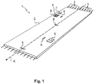
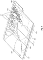
- the predalle 1 according to the first embodiment of the invention comprises a concrete body 2 extending longitudinally along an axis X.
- the concrete body 2 thus comprises two main faces, an upper face and a lower face.
- metal reinforcements 3 are anchored in the concrete body 2 so as to extend each longitudinally along the axis X.
- the predalle 1 comprises means for locating a path to be borrow at least one sheath, said locating means being arranged on the upper face of the predalle 1.
- the locating means are here shaped to indicate the paths to be borrowed from the various duct networks intended to cover the pre-slab such as ducting networks for the transmission of electrical energy, for telecommunication and for the transport of fluid (s). .
- the marking means comprise guiding means intended to facilitate the arrangement of the sheaths on the upper face of the predalle 1.
- Said guide means comprise for example several separate jumpers 8 arranged on the upper face of the slab 1 at different locations and secured separately to the slab 1.
- Each jumper 8 is intended to receive one of the sleeves to guide the arrangement of said sheath on the upper side (as more visible to the figure 2 e ).
- Each rider 8 is here anchored in the concrete body 2 of the predalle 1.
- each jumper 8 is shaped so that it can be unfolded and folded.
- each jumper 8 can be folded which allows to manipulate and store the predalle more easily, said jumper 8 then not exceeding or little of the upper face of the predalle 1.
- Each jumper 8 is for example shaped so as to have a plate anchored in the concrete body 2 and two tabs articulated on the plate at two opposite points of the plate to be folded one on the other. When the two tabs are unfolded, they come to bear on one another to form a guide portion of triangular section with the plate.
- the two tabs are provided with their latching means so that when they are unfolded and pressed against each other, they snap together to form a portion of the latch. stronger guidance.
- the guide means also comprise two incorporations 6, 7 which are secured to the pre-slab 1 so as to be protruding from the upper face of the predalle without extending to the lower face of the predalle.
- the intakes 6, 7 therefore do not form a through opening in the pre-slab 1.
- the predalle 1 directly includes an incorporation and this as soon as it leaves the factory.
- the predalle 1 delivered on site thus already includes said incorporation.
- Said incorporation being intended to be used for the introduction of ducts on the upper face of the predalle 1, the predalle 1 thus simplifies the mounting of said network.
- Each of the incorporations 6, 7 is here anchored in the concrete body 2 of the predalle 1.
- each embodiment 6, 7 is shaped so as to serve as a formwork portion for a single additional reservation when pouring the compression slab.
- each embodiment 6, 7 is shaped so that it can be unfolded and folded.
- each incorporation 6, 7 is folded which allows to manipulate and store more easily the predalle 1, each incorporation 6, 7 not exceeding then or little of the upper face of the predalle 1.
- Each embodiment 6, 7 is for example shaped so as to have a bottom anchored in the concrete body 2 of the predalle 1 and four lateral faces articulated on the bottom to be folded over each other and on the bottom. When the four lateral faces are unfolded, each embodiment 6, 7 therefore forms an open cube on the top.
- each embodiment 6, 7 is shaped so as to have a lid closing the incorporation when in the unfolded position.
- each embodiment 6, 7 here comprises an additional wall secured to the four lateral faces to close the top of the cube defined by the four lateral faces of the incorporation when the latter is unfolded.
- the lid here is hinged to the rest of the embodiment 6, 7 concerned to allow easy access to the interior of the embodiment 6, 7.
- the locating means comprise means for visualizing the paths to be taken to the different sheaths.
- the display means associates a distinctive sign with each incorporation.
- the display means associates a different alphanumeric sign with each incorporation 6, 7.
- each embodiment 6, 7 has its alphanumeric sign written on its lid.
- this alphanumeric sign is repeated at other locations of the associated embodiment 6, 7 and in particular, although not exclusively, within the associated embodiment 6, 7. In this way, even if the lid is removed, it is easy for a worker to locate the item.
- the predalle 1 further comprises a reservation 4 extending over the entire height of the concrete body 2 to form a through opening in the predalle 1.
- this reservation 4 is defined by a reservation box 5.
- the reservation box 5 is thus anchored in the concrete body 2 so as to extend over the entire height of the predalle 1 to define the reservation 4.
- the reservation box 5 is able to create not only a first level of formwork at the time of pouring the concrete body 2 to form the reserve 4 through the predalle 1 but is also able to create a second level of formwork when pouring a slab of compression of the floor.
- the reservation box 5 is shaped so that the second portion is articulated on the first portion between a folded position and an unfolded position in which the second portion extends in the extension of the first portion to form the second formwork level.
- the second portion of the reservation box 5 is folded which allows to manipulate and store more easily the predalle 1, the reservation box 5 not then exceeding or little of the upper face of the predalle 1.
- the reservation box 5 is shaped so that in the folded position, the second portion covers the reservation 4 defined by the first portion.
- the reservation 4 is not accessible until the second portion has not been voluntarily unfolded which makes the predalle 1 safer to use especially when it is arranged on the building under construction to form a base of the floor.
- the first portion is, for example, shaped so as to have four lateral faces forming an open cube on the top and the bottom and the second portion is, for example, shaped so as to also have four other lateral faces forming an open cube on the top and the below, each lateral face of the second portion extending in the extension of one of the lateral faces of the first portion.
- the reservation box 5 is shaped so as to have a bottom closing the reservation at the lower face of the predalle.
- the first portion is here shaped so as to have an additional wall secured to the four lateral faces to close the bottom of the cube defined by the four lateral faces.
- the reservation box 5 is shaped so as to have a lid closing the reservation box.
- the second portion is here shaped so as to have an additional wall secured to the four lateral faces to close the top of the cube defined by the four lateral faces of the second portion when the latter is unfolded and extends in the extension of the first portion.
- the lid here is hinged to the rest of the second portion to allow easy access to the interior of the reservation 4.
- reservation box 5 and the incorporations 6, 7 are shaped to differentiate the reservation boxes incorporations.
- the reservation box 5 is in a first color and the intakes 6, 7 are in a second color different from the first color.
- reservation box 5 also has an alphanumeric sign of its own.
- the reservation box 5 has its alphanumeric sign written on its cover.
- this alphanumeric sign is repeated at other locations of the reservation box 5 and in particular, although not exclusively, inside the reservation box 5. In this way, even if the cover is removed, it is easy for a worker to identify the item.
- a first step we first study the plans for the construction of the floor of which the floor 1 is intended to be part of (for example the plans of the EXE type or else of the DCE type, the execution plans of the fluid network, of the electricity network ).
- each pre-slab 1 of the overall plan incorporating incorporations, reservation boxes and jumpers according to the overall plan.
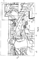
- the method also comprises the step of creating a map dedicated to the slabs (visible at the figure 2d ) and to deliver this card with the different predalles.
- This card is configured to symbolize the predalles and the different embeddings and reservation boxes.
- the intakes and the reservation boxes are schematized on the plane by a geometric shape of the color of the element concerned, the alphanumeric sign of the element concerned being also noted on the plane next to the geometrical shape. .
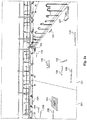
- the worker arranges the slabs 101, 201 on a network of shoring beams (not visible here).
- a second step illustrated in figure 2b the worker arranges some of the metal reinforcements 20 of structural support of the floor.
- a third step illustrated in Figure 2c the worker proceeds to unfold all the incorporations 106, 107, 206 and reservation boxes 104, 204. This makes it possible to prepare the intakes and the reservation boxes for casting the compression slab.
- the various sheaths 21, 22, 23 are arranged on the pre-slats and connected to the intakes.
- the sheaths 21, 22, 23 are advantageously connected to the slats and guided in their pathways between the various incorporations by the riders 108, 208 which are unfolded and folded around the sheaths as and when the sheaths are placed.
- the dedicated card 10 is configured so that it also symbolizes the different sheaths 21, 22, 23.
- the sheaths 21, 22, 23 are of a different color depending on the type of cables and / or pipes that the sheath concerned contains.
- the sheaths 23 dedicated to electricity are red
- the sheaths 22 dedicated to water are blue
- the sheaths 21 dedicated to the the electricity is black
- the dedicated card 10 correspondingly symbolizes the different sheaths by their color which further facilitates the reading of the dedicated card 10.
- each sheath also includes a symbol associated with the intakes that the sheath concerned is supposed to connect.
- each symbol takes up the alphanumeric signs of the intakes that the sheath associated with said symbol is supposed to connect.
- a sheath to connect the incorporation denoted H1 and incorporation noted H2 comprises the symbol H1-H2.
- This symbol is for example printed on the sheath or worn by a label secured to the sheath.
- each packet then comprises a mention of said color and or said path to be taken (for example, the mention H1-H2 for the package comprising sheaths to connect the incorporation denoted H1 with the incorporation denoted H2).
- the floor is created.
- the reservation boxes 104, 204 have thus made it possible to create openings through the floor and incorporations 106, 107, 206 of the openings passing through only the compression slab 27 and making it possible to have access to the different sheaths connected thereto.
- the floor is completed, it is possible to open the various housings and incorporations to access the interior of said housings and incorporations and allow the arrangement of vertical pipes or to use the ducts connected to different incorporations.
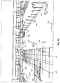
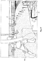
- the predalle 301 comprises a concrete body 302 extending longitudinally along an axis X.
- the concrete body 302 thus comprises two main faces, an upper face and a lower face.
- metal reinforcements 303 are anchored in the concrete body 302 so as to extend each longitudinally along the axis X.
- the predalle 301 comprises means for locating a path to be borrow at least one sheath, said locating means being arranged on the upper face of the predalle 301.
- the locating means are here shaped to indicate the paths to be borrowed from the various duct networks intended to cover the pre-slab such as ducting networks for the transmission of electrical energy, for telecommunication and for the transport of fluid (s). .
- the locating means comprise means for visualizing the paths to be taken to different sheaths.
- Said display means here comprise traces 309 (only one of which is referenced here) of the paths to be taken by the different sheaths which are directly represented on the predalle 301.
- the traces 309 are for example painted on the predalle.
- the display means are arranged so that a trace color is associated with each type of duct network (water, gas, electricity, communication ).
- the sheaths themselves are colored with the associated color on the floor 301 which further simplifies the arrangement of the different networks.
- the display means are furthermore designed to represent on the predalle the locations 310 (only one of which is referenced here) of future incorporations to create reservations that do not pass through the predalle but pass through the compression slab intended to be cast. on the predalle.
- the display means are arranged so that the same color is associated for the paths and locations of each type of duct network (water, gas, electricity, communication ).
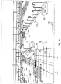
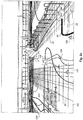
- the figure 4 illustrates an arrangement of four pre-slabs according to the second embodiment of which the predalle 301 which has just been described.
- the four slabs 301, 401, 501, 601 are here arranged on a network of shoring beams at the level where the floor is to be created.
- Each predalle 301, 401, 501, 601 thus includes the paths of the paths to be borrowed by the different duct networks and the plots of the locations of the additional reservations.
- the visualization means are shaped to ensure continuity of the identification of the paths of the various duct networks.
- the different colors associated with the different duct networks are identical for each 301, 401, 501, 601 slab.
- the traces continue from one predalle to another.
- the various ductwork networks are delivered in octopus 311 on the site at the same time as the predalles 301, 401, 501, 601.
- An octopus is a set of branched sheaths made in the factory to be rolled out on site.
- a first octopus comprises the ductwork of the four pre-slabs 301, 401, 501, 601 associated with the transport of electrical energy
- a second octopus comprises the ductwork of the four associated slabs 301, 401, 501, 601. to transport water etc ....
- each octopus 311 further includes the intakes directly arranged in the ductwork.
- each octopus 311 is wound and is secured to the upper face of the associated predalle in at least one point from which the octopus is subsequently unwound.
- sheaths and pre-slabs are joined immediately upon delivery on site, which facilitates the installation of duct systems.
- the worker only has to unwind the ductwork from the point of attachment of each octopus by following the predalle plots and arranging the incorporation at the location of subsequent reservations. Then he only has to form said locations.
- the intakes as the predalle comprise mutual nesting means at the locations. In this way, when the worker unrolls the octopus, he simply has to snap the incorporation on the predalle to complete the assembly of the network.
- the plans for the construction of the floor, the preamble 301 of which is intended to be part of are first studied (for example the plans of the EXE type or else of the DCE type, the execution plans of the fluid network, of the electricity network ).
- the worker arranges the slabs 301, 401, 501, 601 on a network of shoring beams.
- the worker then arranges some of the structural steel reinforcements of the floor.
- the floor is created.
- the possible reservation boxes have thus made it possible to create openings through the floor and incorporations openings passing through only the compression slab 27 and to have access to different sheaths connected thereto.
- the floor is completed, it is possible to open the various housings and incorporations to access the interior of said housings and incorporations and allow the arrangement of vertical pipes or to use the cables and / or pipes present in ducts connected to different incorporations.
- the same predalle may simultaneously include the guiding means of the first embodiment with the display means of the second embodiment.
- incorporations and / or the guide means and / or the riders may not be anchored in the concrete body of the predalle but may only be secured to the concrete body for example by screwing, gluing, interlocking with means already anchored in the concrete body ...
- the reservation boxes and / or the incorporations and / or the guide means may not be unfoldable.
- the reservation boxes and / or incorporations may not include bottom and / or cover.
- the cover may be independent of the rest of the reservation box considered or the rest of the incorporation considered and for example be later fitted on the reservation box or incorporation considered.
- reservation boxes and / or the incorporations may not be sufficient alone to create portions of formwork during the casting of the compression slab.
- the reservation boxes and / or incorporations may include edges on which formwork portions will be nestable which will allow a quick and simple formwork of said incorporation.
- the reservation boxes can serve as a portion of formwork portion to form the reservation in the predalle or that to form the reservation in the compression slab (the reservation in the predalle then being formed other than by the associated reservation box).
- the different steps of the process can be implemented in a different order than what has been indicated. For example we can already start to mount the frames before unfolding the various incorporations and possible booking boxes.
- the visualization means of the path to be borrowed from the sheath can only represent the locations of future incorporations without the duct paths and vice versa.
Landscapes
- Engineering & Computer Science (AREA)
- Architecture (AREA)
- Civil Engineering (AREA)
- Structural Engineering (AREA)
- Mechanical Engineering (AREA)
- Physics & Mathematics (AREA)
- Electromagnetism (AREA)
- Conveying And Assembling Of Building Elements In Situ (AREA)
- Devices For Post-Treatments, Processing, Supply, Discharge, And Other Processes (AREA)
- Agricultural Chemicals And Associated Chemicals (AREA)
- Manufacturing Of Tubular Articles Or Embedded Moulded Articles (AREA)
- Forms Removed On Construction Sites Or Auxiliary Members Thereof (AREA)
Applications Claiming Priority (1)
| Application Number | Priority Date | Filing Date | Title |
|---|---|---|---|
| FR1654762A FR3051810A1 (fr) | 2016-05-27 | 2016-05-27 | Predalle a moyens de reperage de chemins de gaines et procede de fabrication associe |
Publications (3)
| Publication Number | Publication Date |
|---|---|
| EP3249128A2 true EP3249128A2 (de) | 2017-11-29 |
| EP3249128A3 EP3249128A3 (de) | 2018-02-28 |
| EP3249128B1 EP3249128B1 (de) | 2020-01-08 |
Family
ID=56855590
Family Applications (1)
| Application Number | Title | Priority Date | Filing Date |
|---|---|---|---|
| EP17160144.6A Active EP3249128B1 (de) | 2016-05-27 | 2017-03-09 | Elementplatte mit anzeigemitteln der kanalverläufe, und entsprechendes herstellungsverfahren |
Country Status (2)
| Country | Link |
|---|---|
| EP (1) | EP3249128B1 (de) |
| FR (1) | FR3051810A1 (de) |
Cited By (1)
| Publication number | Priority date | Publication date | Assignee | Title |
|---|---|---|---|---|
| CN109016126A (zh) * | 2018-07-10 | 2018-12-18 | 中建钢构有限公司 | 一种基于装配式建筑墙板预埋管线的方法 |
Families Citing this family (2)
| Publication number | Priority date | Publication date | Assignee | Title |
|---|---|---|---|---|
| CN111197371B (zh) * | 2020-01-10 | 2021-11-05 | 山东富海材料科技有限公司 | 一种预应力薄板装配式预制叠合楼板 |
| FR3128326B1 (fr) * | 2021-10-15 | 2024-04-12 | Eaton Intelligent Power Ltd | Dispositif de réservation de câble électrique |
Family Cites Families (10)
| Publication number | Priority date | Publication date | Assignee | Title |
|---|---|---|---|---|
| JP3169818B2 (ja) * | 1995-05-19 | 2001-05-28 | 積水化成品工業株式会社 | 一部の埋込材の表面に凹溝を形成したコンクリートスラブ用基板、該基板を用いたコンクリートスラブの施工方法とその構築物 |
| DE19745385A1 (de) * | 1997-10-14 | 1999-07-29 | Elektro Ebert Gmbh | Verfahren zum Ausführen einer Elektroinstallation und Bausatz für Elektroinstallation |
| FR2804147A1 (fr) * | 2000-01-24 | 2001-07-27 | Laurent Decaix | Collecteur de reservation visitable |
| DE10114340C1 (de) * | 2001-03-23 | 2003-02-20 | Rehau Ag & Co | Verfahren zur Herstellung eines Betonelements sowie Betonelementteils |
| NL1020298C1 (nl) * | 2002-04-03 | 2003-10-07 | Pekso Beton B V | Geïsoleerd aanpasbaar dakelement. Geïsoleerd aanpasbaar dakelement. |
| US20080016805A1 (en) * | 2006-07-19 | 2008-01-24 | Richard Walter | Truss lock floor systems and related methods and apparatus |
| FR2942687B1 (fr) * | 2009-02-27 | 2011-03-11 | Kp1 | Boitier de descente de cables electriques destine a etre integre a une dalle en beton en etant situe au dessus d'une cloison |
| FR2970243B1 (fr) * | 2011-01-11 | 2014-03-14 | Mabamure Soc D Expl | Boite de reservation. |
| FR2970469B1 (fr) * | 2011-01-17 | 2014-03-21 | Rector Lesage | Flan de matiere rigide ou semi-rigide et boite de reservation obtenue par pliage dudit flan |
| NL2010779C2 (nl) * | 2013-05-08 | 2014-11-13 | Jawiho B V | Vloerplaat, werkwijze voor de vervaardiging van een vloerplaat en werkwijze en gebruik van een dergelijke vloerplaat voor het vormen van een vloer in een bouwwerk zoals een gebouw. |
-
2016
- 2016-05-27 FR FR1654762A patent/FR3051810A1/fr not_active Withdrawn
-
2017
- 2017-03-09 EP EP17160144.6A patent/EP3249128B1/de active Active
Non-Patent Citations (1)
| Title |
|---|
| None |
Cited By (1)
| Publication number | Priority date | Publication date | Assignee | Title |
|---|---|---|---|---|
| CN109016126A (zh) * | 2018-07-10 | 2018-12-18 | 中建钢构有限公司 | 一种基于装配式建筑墙板预埋管线的方法 |
Also Published As
| Publication number | Publication date |
|---|---|
| FR3051810A1 (fr) | 2017-12-01 |
| EP3249128A3 (de) | 2018-02-28 |
| EP3249128B1 (de) | 2020-01-08 |
Similar Documents
| Publication | Publication Date | Title |
|---|---|---|
| EP3249128B1 (de) | Elementplatte mit anzeigemitteln der kanalverläufe, und entsprechendes herstellungsverfahren | |
| EP1071986B1 (de) | Verfahren zur generierung einer horizontalen flugbahn die gefährliche bereiche vermeidet | |
| EP2153261B1 (de) | Installation eines faseroptischen netzwerks | |
| US12083915B2 (en) | Vehicle docking stations systems and methods | |
| CA2644393A1 (fr) | Procede et systeme de transport collectif | |
| EP0348278A1 (de) | Verteil- und Verbindungsvorrichtung für optische Fasern | |
| EP1341020A1 (de) | Kassette zum Aufwickeln und Spleissen von optischen Fasern und Verteiler für mehrere solcher Kassetten | |
| EP3249127B1 (de) | Elementplatte, die mindestens ein einbauelement enthält, und herstellungsverfahren einer decke mithilfe dieser elementplatte | |
| CN204790105U (zh) | 一种分光分纤箱 | |
| NL2002006C (nl) | Lashuis. | |
| EP2466707B1 (de) | Bodenkasten zum Einbau in eine Betonplatte oder ein technisches Parkett | |
| JP4766486B2 (ja) | 光接続箱 | |
| JP2017127067A (ja) | 電線共同溝、及びこれに用いる収容ボックス | |
| FR2467107A1 (fr) | Vehicule tel que la remorque d'un ensemble semi-remorque, agence en salle itinerante | |
| FR2699581A1 (fr) | Structure pour la pose de câbles ou de canalisations sous un plancher. | |
| JP4653645B2 (ja) | 光ケーブル接続用クロージャ | |
| JP3285836B2 (ja) | 情報ボックス用管路構造 | |
| EP4108506A1 (de) | Sicherungs- und aufladeeinheit eines e-bikes, sicherungs- und aufladeset, rahmenschloss, aufladeanschluss und flexible fahrradverriegelung | |
| EP0046701B1 (de) | Vorrichtung zum unter- oder oberseitigen Verriegeln zweier sich überlappender Brückenteile und damit versehenes Brückenteil | |
| JP2011185975A (ja) | 光コネクタキット | |
| FR3118471A1 (fr) | Embase de montage pour une boîte de réservation et procédé de fabrication d’une prédalle incorporant cette embase | |
| FR3044086A1 (fr) | Procede et dispositif de calcul d'une trajectoire securisee depuis la position courante d'un aeronef jusqu'a un point d'attache | |
| CA2524888C (fr) | Systeme de coffrage modulaire | |
| FR3065434A1 (fr) | Systeme de platines modulaires pour station d'accueil de cycles | |
| FR2903440A1 (fr) | Corps modulaire pour menager une reserve dans une paroi formee par moulage d'un materiau, beton ou materiau analogue notamment. |
Legal Events
| Date | Code | Title | Description |
|---|---|---|---|
| PUAI | Public reference made under article 153(3) epc to a published international application that has entered the european phase |
Free format text: ORIGINAL CODE: 0009012 |
|
| STAA | Information on the status of an ep patent application or granted ep patent |
Free format text: STATUS: THE APPLICATION HAS BEEN PUBLISHED |
|
| AK | Designated contracting states |
Kind code of ref document: A2 Designated state(s): AL AT BE BG CH CY CZ DE DK EE ES FI FR GB GR HR HU IE IS IT LI LT LU LV MC MK MT NL NO PL PT RO RS SE SI SK SM TR |
|
| AX | Request for extension of the european patent |
Extension state: BA ME |
|
| PUAL | Search report despatched |
Free format text: ORIGINAL CODE: 0009013 |
|
| AK | Designated contracting states |
Kind code of ref document: A3 Designated state(s): AL AT BE BG CH CY CZ DE DK EE ES FI FR GB GR HR HU IE IS IT LI LT LU LV MC MK MT NL NO PL PT RO RS SE SI SK SM TR |
|
| AX | Request for extension of the european patent |
Extension state: BA ME |
|
| RIC1 | Information provided on ipc code assigned before grant |
Ipc: E04B 5/38 20060101AFI20180124BHEP Ipc: E04B 5/48 20060101ALI20180124BHEP Ipc: E04G 15/06 20060101ALI20180124BHEP |
|
| STAA | Information on the status of an ep patent application or granted ep patent |
Free format text: STATUS: REQUEST FOR EXAMINATION WAS MADE |
|
| 17P | Request for examination filed |
Effective date: 20180827 |
|
| RBV | Designated contracting states (corrected) |
Designated state(s): AL AT BE BG CH CY CZ DE DK EE ES FI FR GB GR HR HU IE IS IT LI LT LU LV MC MK MT NL NO PL PT RO RS SE SI SK SM TR |
|
| STAA | Information on the status of an ep patent application or granted ep patent |
Free format text: STATUS: EXAMINATION IS IN PROGRESS |
|
| 17Q | First examination report despatched |
Effective date: 20190423 |
|
| GRAP | Despatch of communication of intention to grant a patent |
Free format text: ORIGINAL CODE: EPIDOSNIGR1 |
|
| STAA | Information on the status of an ep patent application or granted ep patent |
Free format text: STATUS: GRANT OF PATENT IS INTENDED |
|
| INTG | Intention to grant announced |
Effective date: 20190808 |
|
| GRAS | Grant fee paid |
Free format text: ORIGINAL CODE: EPIDOSNIGR3 |
|
| GRAA | (expected) grant |
Free format text: ORIGINAL CODE: 0009210 |
|
| STAA | Information on the status of an ep patent application or granted ep patent |
Free format text: STATUS: THE PATENT HAS BEEN GRANTED |
|
| AK | Designated contracting states |
Kind code of ref document: B1 Designated state(s): AL AT BE BG CH CY CZ DE DK EE ES FI FR GB GR HR HU IE IS IT LI LT LU LV MC MK MT NL NO PL PT RO RS SE SI SK SM TR |
|
| REG | Reference to a national code |
Ref country code: GB Ref legal event code: FG4D Free format text: NOT ENGLISH |
|
| REG | Reference to a national code |
Ref country code: CH Ref legal event code: EP |
|
| REG | Reference to a national code |
Ref country code: DE Ref legal event code: R096 Ref document number: 602017010528 Country of ref document: DE |
|
| REG | Reference to a national code |
Ref country code: IE Ref legal event code: FG4D Free format text: LANGUAGE OF EP DOCUMENT: FRENCH |
|
| REG | Reference to a national code |
Ref country code: AT Ref legal event code: REF Ref document number: 1222888 Country of ref document: AT Kind code of ref document: T Effective date: 20200215 |
|
| REG | Reference to a national code |
Ref country code: NL Ref legal event code: MP Effective date: 20200108 |
|
| REG | Reference to a national code |
Ref country code: LT Ref legal event code: MG4D |
|
| PG25 | Lapsed in a contracting state [announced via postgrant information from national office to epo] |
Ref country code: PT Free format text: LAPSE BECAUSE OF FAILURE TO SUBMIT A TRANSLATION OF THE DESCRIPTION OR TO PAY THE FEE WITHIN THE PRESCRIBED TIME-LIMIT Effective date: 20200531 Ref country code: RS Free format text: LAPSE BECAUSE OF FAILURE TO SUBMIT A TRANSLATION OF THE DESCRIPTION OR TO PAY THE FEE WITHIN THE PRESCRIBED TIME-LIMIT Effective date: 20200108 Ref country code: FI Free format text: LAPSE BECAUSE OF FAILURE TO SUBMIT A TRANSLATION OF THE DESCRIPTION OR TO PAY THE FEE WITHIN THE PRESCRIBED TIME-LIMIT Effective date: 20200108 Ref country code: NO Free format text: LAPSE BECAUSE OF FAILURE TO SUBMIT A TRANSLATION OF THE DESCRIPTION OR TO PAY THE FEE WITHIN THE PRESCRIBED TIME-LIMIT Effective date: 20200408 Ref country code: NL Free format text: LAPSE BECAUSE OF FAILURE TO SUBMIT A TRANSLATION OF THE DESCRIPTION OR TO PAY THE FEE WITHIN THE PRESCRIBED TIME-LIMIT Effective date: 20200108 Ref country code: LT Free format text: LAPSE BECAUSE OF FAILURE TO SUBMIT A TRANSLATION OF THE DESCRIPTION OR TO PAY THE FEE WITHIN THE PRESCRIBED TIME-LIMIT Effective date: 20200108 |
|
| PG25 | Lapsed in a contracting state [announced via postgrant information from national office to epo] |
Ref country code: IS Free format text: LAPSE BECAUSE OF FAILURE TO SUBMIT A TRANSLATION OF THE DESCRIPTION OR TO PAY THE FEE WITHIN THE PRESCRIBED TIME-LIMIT Effective date: 20200508 Ref country code: LV Free format text: LAPSE BECAUSE OF FAILURE TO SUBMIT A TRANSLATION OF THE DESCRIPTION OR TO PAY THE FEE WITHIN THE PRESCRIBED TIME-LIMIT Effective date: 20200108 Ref country code: BG Free format text: LAPSE BECAUSE OF FAILURE TO SUBMIT A TRANSLATION OF THE DESCRIPTION OR TO PAY THE FEE WITHIN THE PRESCRIBED TIME-LIMIT Effective date: 20200408 Ref country code: SE Free format text: LAPSE BECAUSE OF FAILURE TO SUBMIT A TRANSLATION OF THE DESCRIPTION OR TO PAY THE FEE WITHIN THE PRESCRIBED TIME-LIMIT Effective date: 20200108 Ref country code: HR Free format text: LAPSE BECAUSE OF FAILURE TO SUBMIT A TRANSLATION OF THE DESCRIPTION OR TO PAY THE FEE WITHIN THE PRESCRIBED TIME-LIMIT Effective date: 20200108 |
|
| REG | Reference to a national code |
Ref country code: DE Ref legal event code: R119 Ref document number: 602017010528 Country of ref document: DE |
|
| PG25 | Lapsed in a contracting state [announced via postgrant information from national office to epo] |
Ref country code: EE Free format text: LAPSE BECAUSE OF FAILURE TO SUBMIT A TRANSLATION OF THE DESCRIPTION OR TO PAY THE FEE WITHIN THE PRESCRIBED TIME-LIMIT Effective date: 20200108 Ref country code: SM Free format text: LAPSE BECAUSE OF FAILURE TO SUBMIT A TRANSLATION OF THE DESCRIPTION OR TO PAY THE FEE WITHIN THE PRESCRIBED TIME-LIMIT Effective date: 20200108 Ref country code: DK Free format text: LAPSE BECAUSE OF FAILURE TO SUBMIT A TRANSLATION OF THE DESCRIPTION OR TO PAY THE FEE WITHIN THE PRESCRIBED TIME-LIMIT Effective date: 20200108 Ref country code: SK Free format text: LAPSE BECAUSE OF FAILURE TO SUBMIT A TRANSLATION OF THE DESCRIPTION OR TO PAY THE FEE WITHIN THE PRESCRIBED TIME-LIMIT Effective date: 20200108 Ref country code: MC Free format text: LAPSE BECAUSE OF FAILURE TO SUBMIT A TRANSLATION OF THE DESCRIPTION OR TO PAY THE FEE WITHIN THE PRESCRIBED TIME-LIMIT Effective date: 20200108 Ref country code: CZ Free format text: LAPSE BECAUSE OF FAILURE TO SUBMIT A TRANSLATION OF THE DESCRIPTION OR TO PAY THE FEE WITHIN THE PRESCRIBED TIME-LIMIT Effective date: 20200108 Ref country code: ES Free format text: LAPSE BECAUSE OF FAILURE TO SUBMIT A TRANSLATION OF THE DESCRIPTION OR TO PAY THE FEE WITHIN THE PRESCRIBED TIME-LIMIT Effective date: 20200108 Ref country code: RO Free format text: LAPSE BECAUSE OF FAILURE TO SUBMIT A TRANSLATION OF THE DESCRIPTION OR TO PAY THE FEE WITHIN THE PRESCRIBED TIME-LIMIT Effective date: 20200108 |
|
| REG | Reference to a national code |
Ref country code: CH Ref legal event code: PL |
|
| PLBE | No opposition filed within time limit |
Free format text: ORIGINAL CODE: 0009261 |
|
| STAA | Information on the status of an ep patent application or granted ep patent |
Free format text: STATUS: NO OPPOSITION FILED WITHIN TIME LIMIT |
|
| REG | Reference to a national code |
Ref country code: AT Ref legal event code: MK05 Ref document number: 1222888 Country of ref document: AT Kind code of ref document: T Effective date: 20200108 |
|
| 26N | No opposition filed |
Effective date: 20201009 |
|
| REG | Reference to a national code |
Ref country code: BE Ref legal event code: MM Effective date: 20200331 |
|
| PG25 | Lapsed in a contracting state [announced via postgrant information from national office to epo] |
Ref country code: LU Free format text: LAPSE BECAUSE OF NON-PAYMENT OF DUE FEES Effective date: 20200309 |
|
| PG25 | Lapsed in a contracting state [announced via postgrant information from national office to epo] |
Ref country code: IT Free format text: LAPSE BECAUSE OF FAILURE TO SUBMIT A TRANSLATION OF THE DESCRIPTION OR TO PAY THE FEE WITHIN THE PRESCRIBED TIME-LIMIT Effective date: 20200108 Ref country code: IE Free format text: LAPSE BECAUSE OF NON-PAYMENT OF DUE FEES Effective date: 20200309 Ref country code: CH Free format text: LAPSE BECAUSE OF NON-PAYMENT OF DUE FEES Effective date: 20200331 Ref country code: AT Free format text: LAPSE BECAUSE OF FAILURE TO SUBMIT A TRANSLATION OF THE DESCRIPTION OR TO PAY THE FEE WITHIN THE PRESCRIBED TIME-LIMIT Effective date: 20200108 Ref country code: DE Free format text: LAPSE BECAUSE OF NON-PAYMENT OF DUE FEES Effective date: 20201001 Ref country code: LI Free format text: LAPSE BECAUSE OF NON-PAYMENT OF DUE FEES Effective date: 20200331 |
|
| PG25 | Lapsed in a contracting state [announced via postgrant information from national office to epo] |
Ref country code: SI Free format text: LAPSE BECAUSE OF FAILURE TO SUBMIT A TRANSLATION OF THE DESCRIPTION OR TO PAY THE FEE WITHIN THE PRESCRIBED TIME-LIMIT Effective date: 20200108 Ref country code: PL Free format text: LAPSE BECAUSE OF FAILURE TO SUBMIT A TRANSLATION OF THE DESCRIPTION OR TO PAY THE FEE WITHIN THE PRESCRIBED TIME-LIMIT Effective date: 20200108 Ref country code: BE Free format text: LAPSE BECAUSE OF NON-PAYMENT OF DUE FEES Effective date: 20200331 |
|
| GBPC | Gb: european patent ceased through non-payment of renewal fee |
Effective date: 20210309 |
|
| PG25 | Lapsed in a contracting state [announced via postgrant information from national office to epo] |
Ref country code: GB Free format text: LAPSE BECAUSE OF NON-PAYMENT OF DUE FEES Effective date: 20210309 |
|
| PG25 | Lapsed in a contracting state [announced via postgrant information from national office to epo] |
Ref country code: TR Free format text: LAPSE BECAUSE OF FAILURE TO SUBMIT A TRANSLATION OF THE DESCRIPTION OR TO PAY THE FEE WITHIN THE PRESCRIBED TIME-LIMIT Effective date: 20200108 Ref country code: MT Free format text: LAPSE BECAUSE OF FAILURE TO SUBMIT A TRANSLATION OF THE DESCRIPTION OR TO PAY THE FEE WITHIN THE PRESCRIBED TIME-LIMIT Effective date: 20200108 Ref country code: CY Free format text: LAPSE BECAUSE OF FAILURE TO SUBMIT A TRANSLATION OF THE DESCRIPTION OR TO PAY THE FEE WITHIN THE PRESCRIBED TIME-LIMIT Effective date: 20200108 |
|
| PG25 | Lapsed in a contracting state [announced via postgrant information from national office to epo] |
Ref country code: MK Free format text: LAPSE BECAUSE OF FAILURE TO SUBMIT A TRANSLATION OF THE DESCRIPTION OR TO PAY THE FEE WITHIN THE PRESCRIBED TIME-LIMIT Effective date: 20200108 Ref country code: AL Free format text: LAPSE BECAUSE OF FAILURE TO SUBMIT A TRANSLATION OF THE DESCRIPTION OR TO PAY THE FEE WITHIN THE PRESCRIBED TIME-LIMIT Effective date: 20200108 |
|
| PG25 | Lapsed in a contracting state [announced via postgrant information from national office to epo] |
Ref country code: GR Free format text: LAPSE BECAUSE OF FAILURE TO SUBMIT A TRANSLATION OF THE DESCRIPTION OR TO PAY THE FEE WITHIN THE PRESCRIBED TIME-LIMIT Effective date: 20200108 |
|
| P01 | Opt-out of the competence of the unified patent court (upc) registered |
Effective date: 20230601 |
|
| PGFP | Annual fee paid to national office [announced via postgrant information from national office to epo] |
Ref country code: FR Payment date: 20250325 Year of fee payment: 9 |