EP3249124A1 - Fahrzeug zur kanalreinigung - Google Patents
Fahrzeug zur kanalreinigung Download PDFInfo
- Publication number
- EP3249124A1 EP3249124A1 EP17020176.8A EP17020176A EP3249124A1 EP 3249124 A1 EP3249124 A1 EP 3249124A1 EP 17020176 A EP17020176 A EP 17020176A EP 3249124 A1 EP3249124 A1 EP 3249124A1
- Authority
- EP
- European Patent Office
- Prior art keywords
- boom
- vehicle according
- vehicle
- holding device
- coupling half
- Prior art date
- Legal status (The legal status is an assumption and is not a legal conclusion. Google has not performed a legal analysis and makes no representation as to the accuracy of the status listed.)
- Granted
Links
Images


Classifications
-
- E—FIXED CONSTRUCTIONS
- E03—WATER SUPPLY; SEWERAGE
- E03F—SEWERS; CESSPOOLS
- E03F7/00—Other installations or implements for operating sewer systems, e.g. for preventing or indicating stoppage; Emptying cesspools
- E03F7/10—Wheeled apparatus for emptying sewers or cesspools
- E03F7/106—Accessories, e.g. hose support
-
- E—FIXED CONSTRUCTIONS
- E03—WATER SUPPLY; SEWERAGE
- E03F—SEWERS; CESSPOOLS
- E03F7/00—Other installations or implements for operating sewer systems, e.g. for preventing or indicating stoppage; Emptying cesspools
-
- E—FIXED CONSTRUCTIONS
- E03—WATER SUPPLY; SEWERAGE
- E03F—SEWERS; CESSPOOLS
- E03F9/00—Arrangements or fixed installations methods or devices for cleaning or clearing sewer pipes, e.g. by flushing
-
- E—FIXED CONSTRUCTIONS
- E03—WATER SUPPLY; SEWERAGE
- E03F—SEWERS; CESSPOOLS
- E03F9/00—Arrangements or fixed installations methods or devices for cleaning or clearing sewer pipes, e.g. by flushing
- E03F9/007—Devices providing a flushing surge
Definitions
- the invention relates to a vehicle for sewer cleaning, etc., with a container for the water required for the sewer cleaning and / or the sludge resulting from the sewer cleaning and with a boom which is accommodated on the container, preferably rotatable about a stationary axis and / or raised and lowered for manipulating a flushing hose, which can be acted upon by pressurized water and can be introduced into the duct, and / or a suction hose, which can be charged with a suction draft and lowered into the duct.
- Sewer cleaning vehicles of this type are known in various designs.
- the hereby feasible channel works are primarily cleaning operations.
- additional equipment is usually required. If such are provided, they must be brought to the place of use and manipulated there. If a sewer cleaning vehicle could be used for this purpose, its area of application would be widened and its profitability improved.
- the additional implement is loosely on the vehicle receivable and releasably coupled to the boom, it is ensured that the additional implement, if it should be used, removed by means of the boom of the holding device, manipulated in accordance with the intended use and after Termination of the insert can be returned to the holding device. In addition, it can be secured by the boom when driving the vehicle. As long as the implement is not needed, it does not hang on the boom, so this is not burdened by other work hereby and no corresponding space is occupied on the boom.
- the additional implement neither permanently connected to the vehicle-side holding device with the boom, but is removable, it is advantageously also possible to provide different tools that form change units and carried only when needed on the vehicle and attached to the boom can.
- the coupling device may expediently have a coupling half provided on the side of the boom with two clamping jaws which can be adjusted relative to one another by means of an associated drive device designed as a hydraulic cylinder, and a coupling half provided on the work implement side with an engagement element insertable between the clamping jaws.
- At least one element of a coupling half a Have recess in which an associated projection of an element of the other coupling half is inserted. In this way, a positive connection and thus a high level of security results.
- a further advantageous measure may consist in that the working device is assigned a support frame which can be brought into engagement with the vehicle-side holding device and which has the additional working device associated coupling half. In this way, a very simple and obvious construction is achieved, wherein the support frame takes over the connection function to the boom and the holding device, so that the implement itself can be free of appropriate facilities.
- the boom can be telescopically extendable, wherein the boom-side coupling half is expediently attached to the telescopically extendable extension part of the boom.
- the boom-side coupling half is expediently attached to the telescopically extendable extension part of the boom.
- the implementation of the coupling process is facilitated.
- This advantage can be further enhanced by the fact that at least one rear, telescopically extendable section of the cantilever can be raised and lowered, so that both an axial movement and a vertical movement are available for the coupling process.
- the holding device can be provided in the region of the rear side of the container. This allows for convenient handling and space-saving accommodation of the additional implement. To promote this advantage may be provided in the region of the rear end of the container one of the holding device associated, rearwardly open niche into which the implement can at least partially submerge.
- a further, expedient measure may consist in that the holding device is designed as a suspension element, expediently in the form of at least one rearwardly projecting support rod or stirrup. This is ensures that the additional implement or this receiving support frame can be simply pushed onto the support rod or deducted from this.
- Fields of application of the invention are channel cleaning vehicles which are not only used for cleaning purposes but also in carrying out further channel work, e.g. an inspection of the channel by means of a camera introduced into the channel and / or performing remedial work, etc.
- additional equipment in the form of appropriately trained special equipment is needed, which can be recorded on the vehicle and manipulated by means of it should.
- Underlying sewer cleaning vehicle includes in a conventional manner a mobile chassis 1, a recorded on this, appropriately barrel-shaped container 2, a boom 3 received thereon, as well as a one insertable into the channel flushing hose 4 associated Rinsing hose reel 5 and a suction hose 6 associated with a suction hose 6 which can be lowered into the channel.
- the drum-shaped container 2 is divided into several chambers, preferably in the form of a water tank for the rinsing water required for channel cleaning, and a sludge tank for receiving the water during channel cleaning subdivided sludge.
- a pivot cover 8 is provided, which is opened to empty the sludge container. To empty the mud tank, the container 2 can be tilted forward or be provided with a Ausschubkolben.
- the flushing hose 4 and the suction hose 6 run over the boom 3 in the channel and can therefore be manipulated by means of the boom 3.
- This is telescopically extendable to the rear and accordingly contains a pushed out from an associated support member 3a to the rear extension part 3b.
- the support member 3a is connected via a step 3c with a bearing part 3d, which contains the support of the boom 3.
- This is rotatably mounted on the container 2 about a standing axis.
- the Spülschlauchhaspel 5 and Saugschlauchhaspel 7 are arranged in the example shown with the axis of the boom 3 coaxial axis one above the other.
- the reel package thus formed is placed in the niche formed by the step 3c of the boom 3.
- a suitable for performing a sewer inspection implement 9 is carried on the sewer cleaning vehicle, which can be manipulated in use by means of the boom 3 and otherwise deductible on a vehicle-mounted holding device 10.
- the implement 9 consists of a reel 11 rotatably mounted about a horizontal axis for a special high-pressure hose to which a special nozzle 12 equipped with a camera is connected. This is equipped with return nozzles, which are arranged so that a Vvorschubkraft results and the camera is held at the desired height.
- the reel 11 is expediently mounted on a supporting frame 13 forming part of the working device 9.
- the provided with its own support work implement 13 forms a separate from sewer cleaning vehicle unit.
- Such a working device 9 can be carried as an accessory and connected to the boom 3 if necessary. This ensures that the boom 3 does not have to carry the implement permanently, but only when necessary.
- the carried on the sewer cleaning vehicle implement 9 is loosely on the associated, provided on the vehicle side holding device 10 can be accommodated.
- the support frame 13 of the working device 9 is brought into loose engagement with the holding device 10.
- the implement 9 can be connected by means of a coupling device 14 to the boom 3, by which it can be removed in this way from the holding device 10, manipulated in the intended use and then returned to the holding device 10.
- the coupling device 14 includes according to Fig. 2 a cantilever side provided coupling half with two by means of an associated drive means 15 which may be formed as a hydraulic cylinder, mutually adjustable jaws 16, 17, and a working device side provided coupling half with a clamped between the jaws 16, 17 engaging element, suitably in the form of a clamping plate 18.
- the boom 3 associated coupling half is suitably arranged in the region of a side edge of the extension part 3 b of the boom 3.
- the working device side provided coupling half here in the form of the clamping plate 18 is provided at the top of the support frame 13 and connected to this supporting.
- the support frame 13 is connected via a rotary joint 20 with the clamping plate 18. This makes it possible, the coupled to the boom 3 and thus manipulatable implement 9 about the axis of the Rotate pivot 20, which allows a steering of the introduced into the channel, running from the reel 11 special high pressure hose of the implement 9.
- the implement 9, as out Fig. 1 can be seen on the boom 3 and can be manipulated by means of which, ie the special high-pressure hose of the implement 9, which can run directly from the associated reel 11 via the boom 3 in the channel can be manipulated by appropriate actuation of the boom 3.
- the jaws 16, 17 parked from each other are brought by means of the jib 3 into a position flanking the clamping plate 18 and then approached to one another, so that a clamping of the clamping plate 18 takes place.
- the jaws 16, 17 are moved apart and brought out of engagement with the clamping plate 18.
- the boom 3 can be swung laterally and / or raised.
- the extension part 3b of the jib 3 carrying the jib-side coupling half is mounted in the supporting part 3a and therefore can be raised and lowered with it.
- the support member 3a is pivotally connected in the illustrated example with the gradation 3c and provided with a suitable lifting device 21.
- the above-mentioned vehicle-mounted holding device 10 is expediently arranged in the region of the rear side of the container 2.
- the holding device 10 as a suspension device forming, from the container. 2 formed rearwardly projecting support bar or - bracket assembly.
- one or advantageously a plurality of parallel support rods or bracket assemblies may be provided to ensure a stable recording of the implement to form the holding device.
- the entrained implement 9 with its support frame 13 can be simply pushed or deducted from this again.
- the coupling device 14, as in Fig. 3 shown, closed so that the implement 9 is coupled to the boom 3 and can be brought by means of which in and out of engagement with the holding device 10.
- this is from the Fig. 3 underlying driving position in the in Fig. 1 shown working position.
- This is accomplished in the illustrated example, characterized in that the extension part 3b of the boom 3 is extended to the rear.
- the coupling device 14 is opened and the boom 3 is moved so that the working device side coupling half forming clamping plate 18 is released.
- the support member 3 a of the boom 3 is simply tilted so far that the clamping plate 18 completely from the gap between the two jaws 16, 17 emerges.
- a separate lock can be provided.
- the fuse can be done by means of the boom 3 by after the completion of postponement of the implement 9 on the holding device 10, the coupling device 14 according to Fig. 3 remains closed or the boom 3 in the the Fig. 3 brought underlying position and the clutch device 14 are closed.
- a holding device 10 associated, rearwardly open, projecting into the container 2 in niche 22 is provided, in which the recorded on the holding device 10 working device 9 according to FIG Fig. 3 At least partially immersed, which allows space-saving accommodation in the driving position and reduces the vehicle length.
- the cover wall 23 indicated in the drawings by a broken line, which is normally bulged towards the rear, can simply be curved inwards.
- the loosely on the holding device 10 recordable and engageable in and out of coupling with the boom 3 working device 9 can also be easily unloaded and replaced by another implement for other channel works.
- the various implements can be added as change units alternatively on the holding device 10 and brought into coupling engagement with the boom 3.
- the example described is based on a working device 9 provided for an inspection of a channel.
- Apparatus suitable for cutting concrete, etc. may be of similar construction, with a special high-pressure hose suitable for higher pressure and a special duct nozzle provided with a cutting nozzle being provided.
Landscapes
- Health & Medical Sciences (AREA)
- Life Sciences & Earth Sciences (AREA)
- Engineering & Computer Science (AREA)
- Hydrology & Water Resources (AREA)
- Public Health (AREA)
- Water Supply & Treatment (AREA)
- Sewage (AREA)
- Cleaning In General (AREA)
Abstract
Description
- Die Erfindung betrifft ein Fahrzeug zur Kanalreinigung etc. mit einem Behälter für das bei der Kanalreinigung benötigte Wasser und/oder den bei der Kanalreinigung anfallenden Schlamm und mit einem auf dem Behälter aufgenommenen, vorzugsweise um eine stehende Achse drehbaren und/oder heb- und senkbaren Ausleger zur Manipulation eines mit Druckwasser beaufschlagbaren, in den Kanal einführbaren Spülschlauchs und/oder eines mit Saugzug beaufschlagbaren, in den Kanal absenkbaren Saugschlauchs.
- Kanalreinigungsfahrzeuge dieser Art sind in verschiedenen Ausführungen bekannt. Die hiermit durchführbaren Kanalarbeiten sind in erster Linie Reinigungsvorgänge. Für andere, über die Kanalreinigung hinausgehende Kanalarbeiten werden in der Regel zusätzliche Arbeitsgeräte benötigt. Sofern solche vorgesehen sind, müssen diese zum Einsatzort gebracht und dort manipuliert werden. Sofern hierfür ein Kanalreinigungsfahrzeug verwendet werden könnte, würde dessen Einsatzbereich verbreitert und dessen Wirtschaftlichkeit verbessert.
- Hiervon ausgehend ist es daher die Aufgabe der vorliegenden Erfindung, ein Kanalreinigungsfahrzeug eingangs erwähnter Art mit einem vergleichsweise breiten Einsatzbereich zu schaffen.
- Diese Aufgabe wird erfindungsgemäß dadurch gelöst, dass bei einem Fahrzeug eingangs erwähnter Art auf diesem wenigstens ein weiteres, für Kanalarbeiten vorgesehenes Arbeitsgerät mitführbar ist, das auf einer zugeordneten, fahrzeugseitigen Halteeinrichtung lose aufnehmbar und mittels des Auslegers manipulierbar ist und das hierzu mittels einer zugeordneten Kupplungseinrichtung lösbar mit dem Ausleger kuppelbar ist, und so bei Bedarf mittels des Auslegers bestimmungsgemäß manipuliert sowie in in außer Eingriff mit der Halteeinrichtung gebracht werden kann.
- Dadurch, dass das zusätzliche Arbeitsgerät lose auf dem Fahrzeug aufnehmbar und im Bedarfsfall lösbar an den Ausleger ankuppelbar ist, wird sichergestellt, dass das zusätzliche Arbeitsgerät, sofern es zum Einsatz kommen sollte, mittels des Auslegers von der Halteeinrichtung abgenommen, im Einsatz bestimmungsgemäß manipuliert und nach Beendigung des Einsatzes zur Halteeinrichtung zurückgebracht werden kann. Zudem kann es bei Fahrten des Fahrzeugs durch den Ausleger gesichert werden. Solange das Arbeitsgerät nicht benötigt wird, muss es nicht am Ausleger hängen, wodurch dieser bei sonstigen Arbeiten hierdurch nicht belastet wird und kein entsprechender Bauraum am Ausleger belegt wird. Dadurch, dass das zusätzliche Arbeitsgerät weder mit der fahrzeugseitigen Halteeinrichtung noch mit dem Ausleger bleibend verbunden, sondern abnehmbar ist, besteht in vorteilhafter Weise auch die Möglichkeit, verschiedene Arbeitsgeräte vorzusehen, die Wechselaggregate bilden und nur bei Bedarf auf dem Fahrzeug mitgeführt und am Ausleger angebracht werden können.
- Vorteilhafte Ausgestaltungen und zweckmäßige Fortbildungen der übergeordneten Maßnahmen sind in den Unteransprüchen angegeben.
- So kann die Kupplungseinrichtung zweckmäßig eine auslegerseitig vorgesehene Kupplungshälfte mit zwei mittels einer zugeordneten, zweckmäßig als Hydraulikzylinder ausgebildeten Antriebseinrichtung gegeneinander verstellbaren Klemmbacken, und eine arbeitsgeräteseitig vorgesehene Kupplungshälfte mit einem zwischen die Klemmbacken einführbaren Eingriffselement aufweisen. Diese Maßnahmen ergeben in vorteilhafter Weise eine Schnellkuppeleinrichtung, die maschinell betätigbar und daher vom Fahrerhaus bedienbar ist.
- Vorteilhaft kann dabei wenigstens ein Element einer Kupplungshälfte eine Ausnehmung aufweisen, in welche ein zugeordneter Vorsprung eines Elements der anderen Kupplungshälfte einführbar ist. Auf diese Weise ergibt sich eine formschlüssige Verbindung und damit eine hohe Sicherheit.
- Eine weitere vorteilhafte Maßnahme kann darin bestehen, dass dem Arbeitsgerät ein Traggestell zugeordnet ist, das in Eingriff mit der fahrzeugseitigen Halteeinrichtung bringbar ist und die dem zusätzlichen Arbeitsgerät zugeordnete Kupplungshälfte aufweist. Auf diese Weise wird eine sehr einfache und sinnfällige Bauweise erreicht, wobei das Traggestell die Anschlussfunktion an den Ausleger und die Halteeinrichtung übernimmt, so dass das Arbeitsgerät selbst frei von entsprechenden Einrichtungen sein kann.
- Vorteilhaft kann der Ausleger teleskopartig verlängerbar sein, wobei die auslegerseitige Kupplungshälfte zweckmäßig am teleskopartig am ausfahrbaren Verlängerungsteil des Auslegers angebracht ist. Auf diese Weise wird ein großer Aktionsradius für das zusätzliche Arbeitsgerät erreicht. Gleichzeitig wird die Durchführung des Kupplungsvorgangs erleichtert. Dieser Vorteil kann dadurch noch verstärkt werden, dass zumindest ein rückwärtiger, teleskopartig verlängerbarer Abschnitt des Auslegers heb- und senkbar angeordnet ist, so dass für den Kupplungsvorgang sowohl eine Axialbewegung als auch eine Vertikalbewegung zur Verfügung stehen.
- Vorteilhaft kann die Halteeinrichtung im Bereich der Rückseite des Behälters vorgesehen sein. Dies ermöglicht eine günstige Handhabung sowie platzsparende Unterbringung des zusätzlichen Arbeitsgeräts. Zur Förderung dieses Vorteils kann im Bereich des rückwärtigen Endes des Behälters eine der Halteeinrichtung zugeordnete, nach hinten offene Nische vorgesehen sein, in welche das Arbeitsgerät zumindest teilweise eintauchen kann.
- Eine weitere, zweckmäßige Maßnahme kann darin bestehen, dass die Halteeinrichtung als Aufhängeorgan, zweckmäßig in Form mindestens einer nach hinten abstehenden Tragstange bzw. -bügels, ausgebildet ist. Hierdurch ist sichergestellt, dass das zusätzliche Arbeitsgerät bzw. das dieses aufnehmende Traggestell einfach auf die Tragstange aufgeschoben bzw. hiervon abgezogen werden kann.
- Weitere vorteilhafte Ausgestaltungen und zweckmäßige Fortbildungen der übergeordneten Maßnahmen sind in den restlichen Unteransprüchen angegeben und aus der nachstehenden Beschreibung eines bevorzugten Ausführungsbeispiels anhand der Zeichnung näher entnehmbar.
- In der nachstehend beschriebenen Zeichnung zeigen:
- Figur 1
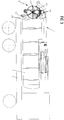
- ein Kanalreinigungsfahrzeug mit einem zusätzlichen Arbeitsgerät zur Durchführung einer Kanalinspektion im Arbeitszustand,
- Figur 2
- die Anordnung gemäß
Figur 1 bei der Durchführung des Kupplungsvorgangs und - Figur 3
- die Anordnung gemäß
Figur 1 im Fahrzustand. - Anwendungsgebiet der Erfindung sind Fahrzeuge zur Kanalreinigung, die nicht nur für Reinigungszwecke eingesetzt werden, sondern auch bei der Durchführung weiterer Kanalarbeiten, z.B. einer Inspektion des Kanals mittels einer in den Kanal eingeführten Kamera und/oder Durchführung von Sanierungsarbeiten etc.. Zur Durchführung solcher zusätzlicher, über die Kanalreinigung hinausgehender Kanalarbeiten werden zusätzliche Arbeitsgeräte in Form entsprechend ausgebildeter Spezialgeräte benötigt, die auf dem Fahrzeug aufgenommen und mittels dessen manipulierbar sein sollen.
- Das den
Figuren 1-3 zugrunde liegende Kanalreinigungsfahrzeug enthält in an sich bekannter Weise eine fahrbare Chassis 1, einen hierauf aufgenommenen, zweckmäßig fassförmigen Behälter 2, einen hierauf aufgenommenen Ausleger 3, sowie eine einem in den Kanal einführbaren Spülschlauch 4 zugeordnete Spülschlauchhaspel 5 und eine einem in den Kanal absenkbaren Saugschlauch 6 zugeordnete Saugschlauchhaspel 7. Der fassförmige Behälter 2 ist durch nicht näher dargestellte Zwischenwände in mehrere Kammern, vorzugsweise in Form eines Wasserbehälters für das bei der Kanalreinigung benötigte Spülwasser und eines Schlammbehälters zur Aufnahme des bei der Kanalreinigung anfallenden Schlamms unterteilt. Am rückwärtigen Ende des Behälters 2 ist ein Schwenkdeckel 8 vorgesehen, der zum Entleeren des Schlammbehälters geöffnet wird. Zum Entleeren des Schlammbehälters kann der Behälter 2 vorne hochgekippt werden oder mit einem Ausschubkolben versehen sein. - Der Spülschlauch 4 und der Saugschlauch 6 laufen über den Ausleger 3 in den Kanal ab und können daher mittels des Auslegers 3 manipuliert werden. Dieser ist teleskopartig nach hinten verlängerbar und enthält dementsprechend ein aus einem zugeordneten Tragteil 3a nach hinten ausschiebbares Ausschubteil 3b. Das Tragteil 3a ist über eine Abstufung 3c mit einem Lagerteil 3d verbunden, das die Lagerung des Auslegers 3 enthält. Dieser ist um eine stehende Achse drehbar auf dem Behälter 2 gelagert. Die Spülschlauchhaspel 5 und die Saugschlauchhaspel 7 sind im dargestellten Beispiel mit zur Achse des Auslegers 3 koaxialer Achse übereinander angeordnet. Das so gebildete Haspelpaket ist in der durch die Abstufung 3c des Auslegers 3 gebildeten Nische platziert.
- Im dargestellten Beispiel wird auf dem Kanalreinigungsfahrzeug ein zur Durchführung einer Kanalinspektion geeignetes Arbeitsgerät 9 mitgeführt, das im Einsatz mittels des Auslegers 3 manipulierbar und sonst auf einer fahrzeugseitigen Halteeinrichtung 10 absetzbar ist. Das Arbeitsgerät 9 besteht im dargestellten Beispiel aus einer um eine horizontale Achse drehbar gelagerten Haspel 11 für einen Spezial-Hochdruckschlauch, an den eine mit einer Kamera ausgestattete Spezial-Kanaldüse 12 angeschlossen ist. Diese ist mit Rückstrahldüsen ausgestattet, die so angeordnet sind, dass sich eine Vvorschubkraft ergibt und die Kamera auf der gewünschten Höhe gehalten wird. Die Haspel 11 ist zweckmäßig auf einem zu der das Arbeitsgerät 9 bildenden Baueinheit gehörenden Traggestell 13 gelagert. Das mit einem eigenen Traggestell versehene Arbeitsgerät 13 bildet eine vom Kanalreinigungsfahrzeug separate Baueinheit. Ein derartiges Arbeitsgerät 9 kann als Zusatzgerät mitgeführt und bei Bedarf an den Ausleger 3 angeschlossen werden. Hierdurch ist sichergestellt, dass der Ausleger 3 das Arbeitsgerät nicht permanent, sondern nur bei Bedarf tragen muss.
- Das auf dem Kanalreinigungsfahrzeug mitgeführte Arbeitsgerät 9 ist lose auf der zugeordneten, fahrzeugseitig vorgesehenen Halteeinrichtung 10 aufnehmbar. Hierzu wird das Traggestell 13 des Arbeitsgeräts 9 mit der Halteeinrichtung 10 in losen Eingriff gebracht. Zur Aktivierung für einen Einsatz kann das Arbeitsgerät 9 mittels einer Kupplungseinrichtung 14 an den Ausleger 3 angeschlossen werden, durch den es auf diese Weise von der Halteeinrichtung 10 abgenommen, im Einsatz bestimmungsgemäß manipuliert und anschließend wieder zur Halteeinrichtung 10 zurückgebracht werden kann. Die Kupplungseinrichtung 14 enthält gemäß
Fig. 2 eine auslegerseitig vorgesehene Kupplungshälfte mit zwei mittels einer zugeordneten Antriebseinrichtung 15, die als Hydraulikzylinder ausgebildet sein kann, gegeneinander verstellbaren Klemmbacken 16, 17, und eine arbeitsgeräteseitig vorgesehene Kupplungshälfte mit einem zwischen die Klemmbacken 16, 17 einklemmbaren Eingriffselement, zweckmäßig in Form einer Klemmplatte 18. Ein Element der Kupplungseinrichtung, zweckmäßig die Klemmplatte 18, ist mit einer Ausnehmung versehen, in die ein Vorsprung 19 eines hiermit zum Eingriff kommenden, anderen Elements der Kupplungseinrichtung zweckmäßig der mittels der Antriebseinrichtung 15 verschiebbaren Klemmbacke 17 einführbar ist. Die genannten Maßnahmen ergeben eine formschlüssige Schnellkuppeleinrichtung. - Die dem Ausleger 3 zugeordnete Kupplungshälfte ist zweckmäßig im Bereich einer Seitenflanke des Ausfahrteils 3b des Auslegers 3 angeordnet. Die arbeitsgeräteseitig vorgesehene Kupplungshälfte, hier in Form der Klemmplatte 18 ist an der Oberseite des Traggestells 13 vorgesehen und mit diesem tragend verbunden. Im dargestellten Beispiel ist das Traggestell 13 über ein Drehgelenk 20 mit der Klemmplatte 18 verbunden. Hierdurch ist es möglich, das an den Ausleger 3 angekuppelte und hiermit manipulierbare Arbeitsgerät 9 um die Achse des Drehgelenks 20 zu drehen, was eine Lenkung des in den Kanal eingeführten, von der Haspel 11 ablaufenden Spezial-Hochdruckschlauchs des Arbeitsgeräts 9 ermöglicht.
- Im Einsatz hängt das Arbeitsgerät 9, wie aus
Fig. 1 erkennbar ist, am Ausleger 3 und kann mittels dessen manipuliert werden, d.h. der Spezial-Hochdruckschlauch des Arbeitsgeräts 9, der direkt von der zugeordneten Haspel 11 über den Ausleger 3 in den Kanal ablaufen kann, kann durch entsprechende Betätigung des Auslegers 3 manipuliert werden. - Zum Ankuppeln des Arbeitsgeräts 9 an den Ausleger 3 werden die voneinander abgestellten Klemmbacken 16, 17 mittels des Auslegers 3 in eine die Klemmplatte 18 flankierende Position gebracht und anschließend aneinander angenähert, so dass eine Klemmung der Klemmplatte 18 erfolgt. Zum Abkuppeln werden die Klemmbacken 16, 17 auseinander bewegt und so außer Eingriff mit der Klemmplatte 18 gebracht. Zum Ein- bzw. Austauchen der Klemmplatte 18 in den bzw. aus dem durch diie Klemmbacken 16, 17 begrenzten Spalt kann der Ausleger 3 seitlich abgeschwenkt und/oder angehoben werden.
- Das die auslegerseitige Kupplungshälfte tragende Ausfahrteil 3b des Auslegers 3 ist im Tragteil 3a gelagert und daher mit diesem heb- und senkbar. Das Tragteil 3a ist im dargestellten Beispiel schwenkbar mit der Abstufung 3c verbunden und mit einer geeigneten Hubeinrichtung 21 versehen. Nach Beendigung eines Einsatzes wird das noch am Ausleger 3 hängende Arbeitsgerät 9 gemäß
Fig. 3 durch entsprechende Betätigung des Auslegers 3 auf der zugeordneten, fahrzeugseitig vorgesehenen Halteeinrichtung 10 abgesetzt, indem das Traggestell 13 durch entsprechende Bewegungen des Auslegers 3 zum Eingriff mit der fahrzeugseitig vorgesehenen Halteeinrichtung 10 gebracht wird. - Die oben bereits erwähnte fahrzeugseitige Halteeinrichtung 10 ist zweckmäßig im Bereich der Rückseite des Behälters 2 angeordnet. Im dargestellten Beispiel ist die Halteeinrichtung 10 als eine Aufhängeeinrichtung bildende, vom Behälter 2 nach hinten abstehende Tragstange bzw. - bügelanordnung ausgebildet. Dabei können zur Bildung der Halteeinrichtung eine oder vorteilhaft mehrere parallele Tragstangen oder Bügelanordnungen vorgesehen sein, um eine stabile Aufnahme des Arbeitsgeräts zu gewährleisten.
- Auf eine derartige Halteeinrichtung 10 kann das mitgeführte Arbeitsgerät 9 mit seinem Traggestell 13 einfach aufgeschoben bzw. hiervon wieder abgezogen werden. Hierzu ist die Kupplungseinrichtung 14, wie in
Fig. 3 gezeigt, geschlossen, so dass das Arbeitsgerät 9 an den Ausleger 3 angekuppelt ist und mittels dessen in und außer Eingriff mit der Halteeinrichtung 10 gebracht werden kann. Zur Aktivierung des Arbeitsgeräts 9 wird dieses von derFig. 3 zugrunde liegenden Fahrposition in die inFig. 1 gezeigte Arbeitspositon gebracht. Dies wird im dargestellten Beispiel dadurch bewerkstelligt, dass das Ausfahrteil 3b des Auslegers 3 nach hinten ausgefahren wird. Nach Beendigung des Einsatzes wird das Arbeitsgerät 3 in umgekehrter Richtung von der Arbeitsposition gemäßFig. 1 in die derFig. 3 zugrunde liegende Fahrstellung gebracht und dabei auf der Halteeinrichtung 10 abgesetzt. - Sofern das Fahrzeug vor Ort bleibt und der Ausleger 3 anderweitig eingesetzt wird, werden das auf der Halteeinrichtung 10 aufgenommene Arbeitsgerät 9 und der Ausleger 3 getrennt. Hierzu werden, wie in
Fig. 2 angedeutet ist, die Kupplungseinrichtung 14 geöffnet und der Ausleger 3 so bewegt, dass die die arbeitsgeräteseitige Kupplungshälfte bildende Klemmplatte 18 freigegeben wird. Im dargestellten Beispiel wird hierzu das Tragteil 3a des Auslegers 3 einfach so weit hochgekippt, dass die Klemmplatte 18 vollständig aus dem Spalt zwischen den beiden Klemmbacken 16, 17 austaucht. Bei einem Standortwechsel, d.h. während das Fahrzeug Fahrbewegungen durchführt, wird das auf der Halteeinrichtung 10 aufgenommene Arbeitsgerät 9 zweckmäßig gesichert. Hierzu kann eine eigene Verriegelung vorgesehen sein. Zweckmäßig kann die Sicherung jedoch mittels des Auslegers 3 erfolgen, indem nach Beendigung des Aufschiebens des Arbeitsgeräts 9 auf die Halteeinrichtung 10 die Kupplungseinrichtung 14 gemäßFig. 3 geschlossen bleibt oder der Ausleger 3 in die derFig. 3 zugrunde liegende Position gebracht und die Kupplungseinrichtung 14 geschlossen werden. - Im dargestellten Beispiel ist im Bereich des rückwärtigen Endes des Behälters 2 eine der Halteeinrichtung 10 zugeordnete, nach hinten offene, in den Behälter 2 hinein vorspringende Nische 22 vorgesehen, in die das auf der Halteeinrichtung 10 aufgenommene Arbeitsgerät 9 gemäß
Fig. 3 zumindest teilweise eintauchen kann, was eine platzsparende Unterbringung in der Fahrposition ermöglicht und die Fahrzeuglänge reduziert. Zur Bildung der in den Behälter 2 hinein vorspringenden Nische 22 kann einfach die in den Zeichnungen durch eine unterbrochene Linie angedeutete Deckelwandung 23, die normalerweise nach hinten ausgewölbt ist, nach innen gewölbt sein. - Das lose auf der Halteeinrichtung 10 aufnehmbare und in und außer Kupplungseingriff mit dem Ausleger 3 bringbare Arbeitsgerät 9 kann auch ohne Weiteres abgeladen und durch ein anderes Arbeitsgerät für andere Kanalarbeiten ersetzt werden. Die verschiedenen Arbeitsgeräte können dabei als Wechselaggregate alternativ auf der Halteeinrichtung 10 aufgenommen und in Kupplungseingriff mit dem Ausleger 3 gebracht werden. Dem beschriebenen Beispiel liegt ein für eine Inspektion eines Kanals vorgesehenes Arbeitsgerät 9 zugrunde. Ein anderes z.B. zum Schneiden von Beton etc. geeignetes Arbeitsgerät kann ähnlich aufgebaut sein, wobei ein für nach höherem Druck geeigneter Spezial-Hochdruckschlauch und eine mit einer Schneiddüse versehene Spezial-Kanaldüse vorzusehen sind.
Claims (12)
- Fahrzeug zur Kanalreinigung etc. mit einem Behälter (2) für das bei der Kanalreinigung benötigte Wasser und/oder den bei der Kanalreinigung anfallenden Schlamm und mit einem auf dem Behälter (2) aufgenommenen, um eine stehende Achse drehbaren und/oder heb- und senkbaren Ausleger (3) zur Manipulation eines mit Druckwasser beaufschlagbaren, in den Kanal einführbaren Spülschlauchs (4) und/oder eines mit Saugzug beaufschlagbaren, in den Kanal absenkbaren Saugschlauchs (6), dadurch gekennzeichnet, dass auf dem Fahrzeug wenigstens ein weiteres, für Kanalarbeiten vorgesehenes Arbeitsgerät (9) mitführbar ist, das auf einer zugeordneten, fahrzeugseitig vorgesehenen Halteeinrichtung (10) lose aufnehmbar und mittels des Auslegers (3) manipulierbar ist und das hierzu mittels einer zugeordneten Kupplungseinrichtung (14) lösbar mit dem Ausleger (3) kuppelbar ist.
- Fahrzeug nach Anspruch 1, dadurch gekennzeichnet, dass die Kupplungseinrichtung (14) eine auslegerseitig vorgesehene Kupplungshälfte mit zwei mittels einer zugeordneten Antriebseinrichtung (15) gegeneinander verstellbaren Klemmbacken (16, 17) und eine arbeitsgeräteseitig vorgesehene Kupplungshälfte mit einem zwischen die Klemmbacken (16, 17) einklemmbaren Eingriffselement (18) aufweist.
- Fahrzeug nach Anspruch 2, dadurch gekennzeichnet, dass wenigstens ein Element einer Kupplungshälfte eine Ausnehmung aufweist, in welche ein zugeordneter Vorsprung (19) eines Elements der jeweils anderen Kupplungshälfte einführbar ist.
- Fahrzeug nach einem der vorhergehenden Ansprüche, dadurch gekennzeichnet, dass dem Arbeitsgerät (9) ein Traggestell (13) zugeordnet ist, das in und außer Eingriff mit der fahrzeugseitigen Halteeinrichtung (10) bringbar ist und die arbeitsgeräteseitig vorgesehene Kupplungshälfte aufweist.
- Fahrzeug nach einem der vorhergehenden Ansprüche, dadurch gekennzeichnet, dass der Ausleger (3) teleskopartig verlängerbar ist und dass die auslegerseitig vorgesehene Kupplungshälfte am teleskopartig ausfahrbaren Verlängerungsteil (3b) des Auslegers angebracht ist.
- Fahrzeug nach Anspruch 5, dadurch gekennzeichnet, dass die auslegerseitig vorgesehene Kupplungshälfte im Bereich einer Seitenflanke des Auslegers (3) vorzugsweise dessen Verlängerungsteils (3b) angebracht ist.
- Fahrzeug nach Anspruch 5 oder 6, dadurch gekennzeichnet, dass der Ausleger (3) ein das Ausfahrteil (3b) aufnehmendes Tragteil (3a) aufweist, das heb- und senkbar an einem Lagerteil (3d) des Auslegers (3) angebracht ist.
- Fahrzeug nach einem der vorhergehenden Ansprüche, dadurch gekennzeichnet, dass die Halteeinrichtung (10) im Bereich der Rückseite des Behälters (2) vorgesehen ist.
- Fahrzeug nach einem der vorhergehenden Ansprüche, dadurch gekennzeichnet, dass der Halteeinrichtung (10) eine in den Behälter (2) vorspringende, nach außen offene Nische (22) zugeordnet ist, in welche das Arbeitsgerät (9) zumindest teilweise eintauchen kann.
- Fahrzeug nach einem der Ansprüche 8 oder 9, dadurch gekennzeichnet, dass die Halteeinrichtung (10) als Aufhängeorgan, vorzugsweise in Form mindestens einer nach hinten abstehenden Tragstange bzw. Tragbügelanordnung ausgebildet ist.
- Fahrzeug nach einem der vorhergehenden Ansprüche, dadurch gekennzeichnet, dass das zusätzliche Arbeitsgerät (9) eine drehbar gelagerte Haspel (11) für einen Spezial-Hochdruckschlauch aufweist, der an seinem vorderen, in den Kanal einführbaren Ende eine mit einer Kamera und/oder einer Schneideinrichtung bestücke Kanaldüse (12) trägt.
- Fahrzeug nach einem der vorhergehenden Ansprüche, dadurch gekennzeichnet, dass alternativ zum Einsatz kommende Arbeitsgeräte als Wechselaggregate alternativ auf der Halteeinrichtung (10) aufnehmbar und mit dem Anleger (3) kuppelbar sind.
Priority Applications (1)
| Application Number | Priority Date | Filing Date | Title |
|---|---|---|---|
| PL17020176T PL3249124T3 (pl) | 2016-05-25 | 2017-04-27 | Pojazd do czyszczenia kanałów kanalizacyjnych |
Applications Claiming Priority (1)
| Application Number | Priority Date | Filing Date | Title |
|---|---|---|---|
| DE102016006276.2A DE102016006276A1 (de) | 2016-05-25 | 2016-05-25 | Fahrzeug zur Kanalreinigung |
Publications (2)
| Publication Number | Publication Date |
|---|---|
| EP3249124A1 true EP3249124A1 (de) | 2017-11-29 |
| EP3249124B1 EP3249124B1 (de) | 2021-07-21 |
Family
ID=58638651
Family Applications (1)
| Application Number | Title | Priority Date | Filing Date |
|---|---|---|---|
| EP17020176.8A Active EP3249124B1 (de) | 2016-05-25 | 2017-04-27 | Fahrzeug zur kanalreinigung |
Country Status (7)
| Country | Link |
|---|---|
| US (1) | US10526778B2 (de) |
| EP (1) | EP3249124B1 (de) |
| CN (1) | CN107435373B (de) |
| DE (1) | DE102016006276A1 (de) |
| DK (1) | DK3249124T3 (de) |
| HU (1) | HUE056165T2 (de) |
| PL (1) | PL3249124T3 (de) |
Cited By (1)
| Publication number | Priority date | Publication date | Assignee | Title |
|---|---|---|---|---|
| CN111792564A (zh) * | 2020-06-20 | 2020-10-20 | 广东旺标建设工程有限公司 | 一种市政地下管道自动清污装置 |
Families Citing this family (4)
| Publication number | Priority date | Publication date | Assignee | Title |
|---|---|---|---|---|
| CN108316463A (zh) * | 2018-04-02 | 2018-07-24 | 无锡圣美环境科技有限公司 | 城市下水道清堵型电动清洗小车 |
| CN110145017B (zh) * | 2019-06-06 | 2020-10-27 | 夏献云 | 一种市政工程下水道清淤设备 |
| CN112681500A (zh) * | 2020-12-14 | 2021-04-20 | 湖北中威专用汽车有限公司 | 一种污水循环再利用式管道疏通吸污车 |
| DE202024103915U1 (de) * | 2024-07-12 | 2024-07-31 | Erhard Weiß | Kanalspülfahrzeug |
Citations (5)
| Publication number | Priority date | Publication date | Assignee | Title |
|---|---|---|---|---|
| FR1145717A (fr) * | 1956-01-07 | 1957-10-29 | Sovel Soc | Véhicule aspirateur de matières liquides ou semi-liquides telles que des boues |
| DE4223931A1 (de) * | 1992-07-21 | 1994-01-27 | Mueller Umwelttechnik | Kanalreinigungsfahrzeug |
| EP0683278A2 (de) * | 1994-05-16 | 1995-11-22 | Karl Wiedemann | Kanalreinigungsfahrzeug |
| DE102004022121A1 (de) * | 2004-05-05 | 2005-12-01 | Karl Wiedemann | Vorrichtung zur Reinigung eines Schmutzfangs |
| EP2993277A1 (de) * | 2014-09-04 | 2016-03-09 | Karl Wiedemann | Vorrichtung zur reinigung und/oder inspektion eines strömungskanals |
Family Cites Families (9)
| Publication number | Priority date | Publication date | Assignee | Title |
|---|---|---|---|---|
| DE3813419C2 (de) | 1988-04-21 | 1999-06-24 | Peter Assmann | Lastfahrzeug mit mindestens einem ein- und ausfahrbaren Schlauch |
| US4922571A (en) * | 1988-11-14 | 1990-05-08 | Aquatech, Inc. | Vacuum loading machine |
| AT397974B (de) * | 1990-05-16 | 1994-08-25 | Kaiser Josef | Saugrüssel für ein saug-druck-fass mit einem saugschlauch |
| AT403712B (de) | 1996-09-13 | 1998-05-25 | Kaiser Ag | Kanalreinigungsfahrzeug |
| IT1307190B1 (it) * | 1999-05-03 | 2001-10-29 | Cappellotto S P A | Struttura di attrezzatura per lo svolgimento/avvolgimento di un tubodi aspirazione per espurgo pozzi neri fosse biologiche o simili. |
| DE10246041B4 (de) * | 2002-10-02 | 2005-05-19 | Müller Umwelttechnik GmbH & Co KG | Saug-Spülfahrzeug |
| FR2908800B1 (fr) * | 2006-11-21 | 2011-04-22 | Veolia Eau Cie Generale Des Eaux | Unite mobile de nettoyage d'un reseau d'egout |
| CN204225265U (zh) * | 2014-11-05 | 2015-03-25 | 秦皇岛市思嘉特专用汽车制造有限公司 | 多功能联合疏通车 |
| CN205077610U (zh) * | 2015-11-06 | 2016-03-09 | 淮安市翔龙特种车辆有限公司 | 一种设置有可伸缩吸污臂的联合吸污车 |
-
2016
- 2016-05-25 DE DE102016006276.2A patent/DE102016006276A1/de not_active Withdrawn
-
2017
- 2017-04-26 US US15/497,686 patent/US10526778B2/en active Active
- 2017-04-27 PL PL17020176T patent/PL3249124T3/pl unknown
- 2017-04-27 DK DK17020176.8T patent/DK3249124T3/da active
- 2017-04-27 EP EP17020176.8A patent/EP3249124B1/de active Active
- 2017-04-27 HU HUE17020176A patent/HUE056165T2/hu unknown
- 2017-05-17 CN CN201710345454.6A patent/CN107435373B/zh active Active
Patent Citations (5)
| Publication number | Priority date | Publication date | Assignee | Title |
|---|---|---|---|---|
| FR1145717A (fr) * | 1956-01-07 | 1957-10-29 | Sovel Soc | Véhicule aspirateur de matières liquides ou semi-liquides telles que des boues |
| DE4223931A1 (de) * | 1992-07-21 | 1994-01-27 | Mueller Umwelttechnik | Kanalreinigungsfahrzeug |
| EP0683278A2 (de) * | 1994-05-16 | 1995-11-22 | Karl Wiedemann | Kanalreinigungsfahrzeug |
| DE102004022121A1 (de) * | 2004-05-05 | 2005-12-01 | Karl Wiedemann | Vorrichtung zur Reinigung eines Schmutzfangs |
| EP2993277A1 (de) * | 2014-09-04 | 2016-03-09 | Karl Wiedemann | Vorrichtung zur reinigung und/oder inspektion eines strömungskanals |
Cited By (1)
| Publication number | Priority date | Publication date | Assignee | Title |
|---|---|---|---|---|
| CN111792564A (zh) * | 2020-06-20 | 2020-10-20 | 广东旺标建设工程有限公司 | 一种市政地下管道自动清污装置 |
Also Published As
| Publication number | Publication date |
|---|---|
| EP3249124B1 (de) | 2021-07-21 |
| DE102016006276A1 (de) | 2017-11-30 |
| CN107435373B (zh) | 2019-10-25 |
| HUE056165T2 (hu) | 2022-01-28 |
| DK3249124T3 (da) | 2021-10-25 |
| CN107435373A (zh) | 2017-12-05 |
| US20170342699A1 (en) | 2017-11-30 |
| PL3249124T3 (pl) | 2021-12-06 |
| US10526778B2 (en) | 2020-01-07 |
| HK1243750A1 (zh) | 2018-07-20 |
Similar Documents
| Publication | Publication Date | Title |
|---|---|---|
| DE102011107167B4 (de) | Reinigungsvorrichtung | |
| EP3249124B1 (de) | Fahrzeug zur kanalreinigung | |
| DE202009003824U1 (de) | Abbaumaschine, insbesondere Surfac Miner | |
| DE102009042687A1 (de) | Kanalreinigungsfahrzeug | |
| EP2995583A1 (de) | Wartungsfreundlicher teleskopierbarer schwenkarm und arbeits- oder betriebsverfahren | |
| EP2236745A2 (de) | Abbaumaschine, insbesondere Surface Miner, sowie Verfahren zum Aus- und Einbauen einer Transporteinrichtung bei einer Abbaumaschine | |
| EP0683278A2 (de) | Kanalreinigungsfahrzeug | |
| DE2204792A1 (de) | Richtvorrichtung für die Rahmen und Aufbauten von Fahrzeugen | |
| DE202016002943U1 (de) | Kanalreinigungsfahrzeug | |
| DE102016012258B4 (de) | Straßengebundenes Kanal-Inspektionsfahrzeug für die Inspektion und Kontrolle von Kanalrohren und deren Konstruktions-Lagemessung | |
| DE3642809A1 (de) | Maschine zum abfraesen oder abschaelen von strassenbelaegen | |
| EP2239121B1 (de) | Fahrmischer | |
| DE3729561C2 (de) | ||
| DE10246041A1 (de) | Saug-Spülfahrzeug | |
| EP3964657B1 (de) | Kanalreinigungsfahrzeug | |
| DE9213605U1 (de) | Druckmaschinenzylinder-Waschvorrichtung | |
| CH686733A5 (de) | Vorrichtung zum Auftragen von Moertel. | |
| DE102004022121A1 (de) | Vorrichtung zur Reinigung eines Schmutzfangs | |
| EP3859092B1 (de) | Kanalreinigungsfahrzeug | |
| DE10144962B4 (de) | Reinigungswerkzeug für Kanäle | |
| AT391787B (de) | Vorrichtung zum entnehmen von silage aus einem fahrsilo | |
| DE3208492A1 (de) | Verfahren und vorrichtung zum einbringen von hohlpfaehlen in den boden | |
| DE19654919B4 (de) | Vorrichtung zum Reinigen von Sinkkästen | |
| DE102017204518A1 (de) | Verfahren zur Kabelrückgewinnung | |
| DE7516598U (de) | Wohnkabine für ein raumfahrzeug |
Legal Events
| Date | Code | Title | Description |
|---|---|---|---|
| PUAI | Public reference made under article 153(3) epc to a published international application that has entered the european phase |
Free format text: ORIGINAL CODE: 0009012 |
|
| STAA | Information on the status of an ep patent application or granted ep patent |
Free format text: STATUS: THE APPLICATION HAS BEEN PUBLISHED |
|
| AK | Designated contracting states |
Kind code of ref document: A1 Designated state(s): AL AT BE BG CH CY CZ DE DK EE ES FI FR GB GR HR HU IE IS IT LI LT LU LV MC MK MT NL NO PL PT RO RS SE SI SK SM TR |
|
| AX | Request for extension of the european patent |
Extension state: BA ME |
|
| STAA | Information on the status of an ep patent application or granted ep patent |
Free format text: STATUS: REQUEST FOR EXAMINATION WAS MADE |
|
| 17P | Request for examination filed |
Effective date: 20180529 |
|
| RBV | Designated contracting states (corrected) |
Designated state(s): AL AT BE BG CH CY CZ DE DK EE ES FI FR GB GR HR HU IE IS IT LI LT LU LV MC MK MT NL NO PL PT RO RS SE SI SK SM TR |
|
| STAA | Information on the status of an ep patent application or granted ep patent |
Free format text: STATUS: EXAMINATION IS IN PROGRESS |
|
| 17Q | First examination report despatched |
Effective date: 20190507 |
|
| GRAP | Despatch of communication of intention to grant a patent |
Free format text: ORIGINAL CODE: EPIDOSNIGR1 |
|
| STAA | Information on the status of an ep patent application or granted ep patent |
Free format text: STATUS: GRANT OF PATENT IS INTENDED |
|
| RIC1 | Information provided on ipc code assigned before grant |
Ipc: E03F 7/10 20060101ALN20210415BHEP Ipc: E03F 9/00 20060101AFI20210415BHEP |
|
| INTG | Intention to grant announced |
Effective date: 20210512 |
|
| GRAS | Grant fee paid |
Free format text: ORIGINAL CODE: EPIDOSNIGR3 |
|
| GRAA | (expected) grant |
Free format text: ORIGINAL CODE: 0009210 |
|
| STAA | Information on the status of an ep patent application or granted ep patent |
Free format text: STATUS: THE PATENT HAS BEEN GRANTED |
|
| AK | Designated contracting states |
Kind code of ref document: B1 Designated state(s): AL AT BE BG CH CY CZ DE DK EE ES FI FR GB GR HR HU IE IS IT LI LT LU LV MC MK MT NL NO PL PT RO RS SE SI SK SM TR |
|
| REG | Reference to a national code |
Ref country code: GB Ref legal event code: FG4D Free format text: NOT ENGLISH |
|
| REG | Reference to a national code |
Ref country code: CH Ref legal event code: EP |
|
| REG | Reference to a national code |
Ref country code: DE Ref legal event code: R096 Ref document number: 502017010929 Country of ref document: DE |
|
| REG | Reference to a national code |
Ref country code: AT Ref legal event code: REF Ref document number: 1412745 Country of ref document: AT Kind code of ref document: T Effective date: 20210815 |
|
| REG | Reference to a national code |
Ref country code: IE Ref legal event code: FG4D Free format text: LANGUAGE OF EP DOCUMENT: GERMAN |
|
| REG | Reference to a national code |
Ref country code: RO Ref legal event code: EPE |
|
| REG | Reference to a national code |
Ref country code: NL Ref legal event code: FP |
|
| REG | Reference to a national code |
Ref country code: DK Ref legal event code: T3 Effective date: 20211020 |
|
| REG | Reference to a national code |
Ref country code: LT Ref legal event code: MG9D |
|
| REG | Reference to a national code |
Ref country code: GR Ref legal event code: EP Ref document number: 20210402503 Country of ref document: GR Effective date: 20211111 |
|
| REG | Reference to a national code |
Ref country code: HU Ref legal event code: AG4A Ref document number: E056165 Country of ref document: HU |
|
| PG25 | Lapsed in a contracting state [announced via postgrant information from national office to epo] |
Ref country code: RS Free format text: LAPSE BECAUSE OF FAILURE TO SUBMIT A TRANSLATION OF THE DESCRIPTION OR TO PAY THE FEE WITHIN THE PRESCRIBED TIME-LIMIT Effective date: 20210721 Ref country code: SE Free format text: LAPSE BECAUSE OF FAILURE TO SUBMIT A TRANSLATION OF THE DESCRIPTION OR TO PAY THE FEE WITHIN THE PRESCRIBED TIME-LIMIT Effective date: 20210721 Ref country code: BG Free format text: LAPSE BECAUSE OF FAILURE TO SUBMIT A TRANSLATION OF THE DESCRIPTION OR TO PAY THE FEE WITHIN THE PRESCRIBED TIME-LIMIT Effective date: 20211021 Ref country code: LT Free format text: LAPSE BECAUSE OF FAILURE TO SUBMIT A TRANSLATION OF THE DESCRIPTION OR TO PAY THE FEE WITHIN THE PRESCRIBED TIME-LIMIT Effective date: 20210721 Ref country code: NO Free format text: LAPSE BECAUSE OF FAILURE TO SUBMIT A TRANSLATION OF THE DESCRIPTION OR TO PAY THE FEE WITHIN THE PRESCRIBED TIME-LIMIT Effective date: 20211021 Ref country code: PT Free format text: LAPSE BECAUSE OF FAILURE TO SUBMIT A TRANSLATION OF THE DESCRIPTION OR TO PAY THE FEE WITHIN THE PRESCRIBED TIME-LIMIT Effective date: 20211122 Ref country code: ES Free format text: LAPSE BECAUSE OF FAILURE TO SUBMIT A TRANSLATION OF THE DESCRIPTION OR TO PAY THE FEE WITHIN THE PRESCRIBED TIME-LIMIT Effective date: 20210721 Ref country code: FI Free format text: LAPSE BECAUSE OF FAILURE TO SUBMIT A TRANSLATION OF THE DESCRIPTION OR TO PAY THE FEE WITHIN THE PRESCRIBED TIME-LIMIT Effective date: 20210721 Ref country code: HR Free format text: LAPSE BECAUSE OF FAILURE TO SUBMIT A TRANSLATION OF THE DESCRIPTION OR TO PAY THE FEE WITHIN THE PRESCRIBED TIME-LIMIT Effective date: 20210721 |
|
| PG25 | Lapsed in a contracting state [announced via postgrant information from national office to epo] |
Ref country code: LV Free format text: LAPSE BECAUSE OF FAILURE TO SUBMIT A TRANSLATION OF THE DESCRIPTION OR TO PAY THE FEE WITHIN THE PRESCRIBED TIME-LIMIT Effective date: 20210721 |
|
| REG | Reference to a national code |
Ref country code: DE Ref legal event code: R097 Ref document number: 502017010929 Country of ref document: DE |
|
| PLBE | No opposition filed within time limit |
Free format text: ORIGINAL CODE: 0009261 |
|
| STAA | Information on the status of an ep patent application or granted ep patent |
Free format text: STATUS: NO OPPOSITION FILED WITHIN TIME LIMIT |
|
| PG25 | Lapsed in a contracting state [announced via postgrant information from national office to epo] |
Ref country code: SM Free format text: LAPSE BECAUSE OF FAILURE TO SUBMIT A TRANSLATION OF THE DESCRIPTION OR TO PAY THE FEE WITHIN THE PRESCRIBED TIME-LIMIT Effective date: 20210721 Ref country code: SK Free format text: LAPSE BECAUSE OF FAILURE TO SUBMIT A TRANSLATION OF THE DESCRIPTION OR TO PAY THE FEE WITHIN THE PRESCRIBED TIME-LIMIT Effective date: 20210721 Ref country code: EE Free format text: LAPSE BECAUSE OF FAILURE TO SUBMIT A TRANSLATION OF THE DESCRIPTION OR TO PAY THE FEE WITHIN THE PRESCRIBED TIME-LIMIT Effective date: 20210721 Ref country code: AL Free format text: LAPSE BECAUSE OF FAILURE TO SUBMIT A TRANSLATION OF THE DESCRIPTION OR TO PAY THE FEE WITHIN THE PRESCRIBED TIME-LIMIT Effective date: 20210721 |
|
| 26N | No opposition filed |
Effective date: 20220422 |
|
| PG25 | Lapsed in a contracting state [announced via postgrant information from national office to epo] |
Ref country code: MC Free format text: LAPSE BECAUSE OF FAILURE TO SUBMIT A TRANSLATION OF THE DESCRIPTION OR TO PAY THE FEE WITHIN THE PRESCRIBED TIME-LIMIT Effective date: 20210721 |
|
| PG25 | Lapsed in a contracting state [announced via postgrant information from national office to epo] |
Ref country code: MK Free format text: LAPSE BECAUSE OF FAILURE TO SUBMIT A TRANSLATION OF THE DESCRIPTION OR TO PAY THE FEE WITHIN THE PRESCRIBED TIME-LIMIT Effective date: 20210721 Ref country code: CY Free format text: LAPSE BECAUSE OF FAILURE TO SUBMIT A TRANSLATION OF THE DESCRIPTION OR TO PAY THE FEE WITHIN THE PRESCRIBED TIME-LIMIT Effective date: 20210721 |
|
| PG25 | Lapsed in a contracting state [announced via postgrant information from national office to epo] |
Ref country code: MT Free format text: LAPSE BECAUSE OF FAILURE TO SUBMIT A TRANSLATION OF THE DESCRIPTION OR TO PAY THE FEE WITHIN THE PRESCRIBED TIME-LIMIT Effective date: 20210721 |
|
| PGFP | Annual fee paid to national office [announced via postgrant information from national office to epo] |
Ref country code: NL Payment date: 20250422 Year of fee payment: 9 |
|
| PGFP | Annual fee paid to national office [announced via postgrant information from national office to epo] |
Ref country code: LU Payment date: 20250417 Year of fee payment: 9 |
|
| PGFP | Annual fee paid to national office [announced via postgrant information from national office to epo] |
Ref country code: PL Payment date: 20250414 Year of fee payment: 9 Ref country code: DE Payment date: 20250430 Year of fee payment: 9 |
|
| PGFP | Annual fee paid to national office [announced via postgrant information from national office to epo] |
Ref country code: DK Payment date: 20250423 Year of fee payment: 9 |
|
| PGFP | Annual fee paid to national office [announced via postgrant information from national office to epo] |
Ref country code: HU Payment date: 20250425 Year of fee payment: 9 |
|
| PGFP | Annual fee paid to national office [announced via postgrant information from national office to epo] |
Ref country code: BE Payment date: 20250422 Year of fee payment: 9 Ref country code: IT Payment date: 20250430 Year of fee payment: 9 |
|
| PGFP | Annual fee paid to national office [announced via postgrant information from national office to epo] |
Ref country code: FR Payment date: 20250424 Year of fee payment: 9 |
|
| PGFP | Annual fee paid to national office [announced via postgrant information from national office to epo] |
Ref country code: GR Payment date: 20250416 Year of fee payment: 9 |
|
| PGFP | Annual fee paid to national office [announced via postgrant information from national office to epo] |
Ref country code: CH Payment date: 20250501 Year of fee payment: 9 |
|
| PGFP | Annual fee paid to national office [announced via postgrant information from national office to epo] |
Ref country code: RO Payment date: 20250414 Year of fee payment: 9 Ref country code: AT Payment date: 20250416 Year of fee payment: 9 |
|
| PGFP | Annual fee paid to national office [announced via postgrant information from national office to epo] |
Ref country code: TR Payment date: 20250418 Year of fee payment: 9 |
|
| PGFP | Annual fee paid to national office [announced via postgrant information from national office to epo] |
Ref country code: CZ Payment date: 20250411 Year of fee payment: 9 |
|
| PGFP | Annual fee paid to national office [announced via postgrant information from national office to epo] |
Ref country code: IE Payment date: 20250428 Year of fee payment: 9 |
|
| PGFP | Annual fee paid to national office [announced via postgrant information from national office to epo] |
Ref country code: GB Payment date: 20260324 Year of fee payment: 10 |
|
| REG | Reference to a national code |
Ref country code: CH Ref legal event code: U11 Free format text: ST27 STATUS EVENT CODE: U-0-0-U10-U11 (AS PROVIDED BY THE NATIONAL OFFICE) Effective date: 20260501 |