EP3249092B1 - Inneretüranordnung für eine trommelwaschmaschine und trommelwaschmaschine damit - Google Patents
Inneretüranordnung für eine trommelwaschmaschine und trommelwaschmaschine damit Download PDFInfo
- Publication number
- EP3249092B1 EP3249092B1 EP17157908.9A EP17157908A EP3249092B1 EP 3249092 B1 EP3249092 B1 EP 3249092B1 EP 17157908 A EP17157908 A EP 17157908A EP 3249092 B1 EP3249092 B1 EP 3249092B1
- Authority
- EP
- European Patent Office
- Prior art keywords
- inner door
- washing machine
- shell
- drum washing
- external shell
- Prior art date
- Legal status (The legal status is an assumption and is not a legal conclusion. Google has not performed a legal analysis and makes no representation as to the accuracy of the status listed.)
- Active
Links
- 238000005406 washing Methods 0.000 title claims description 144
- 230000003811 curling process Effects 0.000 claims description 15
- 238000000034 method Methods 0.000 claims description 14
- 229920003023 plastic Polymers 0.000 claims description 14
- 239000002184 metal Substances 0.000 claims description 13
- 238000002347 injection Methods 0.000 claims description 8
- 239000007924 injection Substances 0.000 claims description 8
- 238000003825 pressing Methods 0.000 claims description 7
- 230000001681 protective effect Effects 0.000 claims description 7
- 229910001220 stainless steel Inorganic materials 0.000 claims description 6
- 239000010935 stainless steel Substances 0.000 claims description 6
- 238000004519 manufacturing process Methods 0.000 claims description 4
- 239000011521 glass Substances 0.000 description 8
- XLYOFNOQVPJJNP-UHFFFAOYSA-N water Substances O XLYOFNOQVPJJNP-UHFFFAOYSA-N 0.000 description 6
- 238000004891 communication Methods 0.000 description 4
- 239000012530 fluid Substances 0.000 description 4
- 239000000463 material Substances 0.000 description 4
- 238000013461 design Methods 0.000 description 3
- 238000001746 injection moulding Methods 0.000 description 3
- 238000010276 construction Methods 0.000 description 2
- 238000005260 corrosion Methods 0.000 description 2
- 230000007797 corrosion Effects 0.000 description 2
- 235000012489 doughnuts Nutrition 0.000 description 2
- -1 for example Substances 0.000 description 2
- 238000012986 modification Methods 0.000 description 2
- 230000004048 modification Effects 0.000 description 2
- 239000000853 adhesive Substances 0.000 description 1
- 230000001070 adhesive effect Effects 0.000 description 1
- 230000000712 assembly Effects 0.000 description 1
- 238000000429 assembly Methods 0.000 description 1
- 230000000903 blocking effect Effects 0.000 description 1
- 238000002144 chemical decomposition reaction Methods 0.000 description 1
- 239000011248 coating agent Substances 0.000 description 1
- 238000000576 coating method Methods 0.000 description 1
- 239000000356 contaminant Substances 0.000 description 1
- 230000003247 decreasing effect Effects 0.000 description 1
- 239000003599 detergent Substances 0.000 description 1
- 230000005611 electricity Effects 0.000 description 1
- 230000003116 impacting effect Effects 0.000 description 1
- 238000007689 inspection Methods 0.000 description 1
- 230000000149 penetrating effect Effects 0.000 description 1
- 238000012545 processing Methods 0.000 description 1
Images


Classifications
-
- D—TEXTILES; PAPER
- D06—TREATMENT OF TEXTILES OR THE LIKE; LAUNDERING; FLEXIBLE MATERIALS NOT OTHERWISE PROVIDED FOR
- D06F—LAUNDERING, DRYING, IRONING, PRESSING OR FOLDING TEXTILE ARTICLES
- D06F37/00—Details specific to washing machines covered by groups D06F21/00 - D06F25/00
- D06F37/02—Rotary receptacles, e.g. drums
- D06F37/04—Rotary receptacles, e.g. drums adapted for rotation or oscillation about a horizontal or inclined axis
- D06F37/10—Doors; Securing means therefor
-
- D—TEXTILES; PAPER
- D06—TREATMENT OF TEXTILES OR THE LIKE; LAUNDERING; FLEXIBLE MATERIALS NOT OTHERWISE PROVIDED FOR
- D06F—LAUNDERING, DRYING, IRONING, PRESSING OR FOLDING TEXTILE ARTICLES
- D06F37/00—Details specific to washing machines covered by groups D06F21/00 - D06F25/00
- D06F37/26—Casings; Tubs
- D06F37/28—Doors; Security means therefor
-
- D—TEXTILES; PAPER
- D06—TREATMENT OF TEXTILES OR THE LIKE; LAUNDERING; FLEXIBLE MATERIALS NOT OTHERWISE PROVIDED FOR
- D06F—LAUNDERING, DRYING, IRONING, PRESSING OR FOLDING TEXTILE ARTICLES
- D06F23/00—Washing machines with receptacles, e.g. perforated, having a rotary movement, e.g. oscillatory movement, the receptacle serving both for washing and for centrifugally separating water from the laundry
-
- D—TEXTILES; PAPER
- D06—TREATMENT OF TEXTILES OR THE LIKE; LAUNDERING; FLEXIBLE MATERIALS NOT OTHERWISE PROVIDED FOR
- D06F—LAUNDERING, DRYING, IRONING, PRESSING OR FOLDING TEXTILE ARTICLES
- D06F39/00—Details of washing machines not specific to a single type of machines covered by groups D06F9/00 - D06F27/00
- D06F39/12—Casings; Tubs
- D06F39/14—Doors or covers; Securing means therefor
-
- E—FIXED CONSTRUCTIONS
- E06—DOORS, WINDOWS, SHUTTERS, OR ROLLER BLINDS IN GENERAL; LADDERS
- E06B—FIXED OR MOVABLE CLOSURES FOR OPENINGS IN BUILDINGS, VEHICLES, FENCES OR LIKE ENCLOSURES IN GENERAL, e.g. DOORS, WINDOWS, BLINDS, GATES
- E06B5/00—Doors, windows, or like closures for special purposes; Border constructions therefor
- E06B5/006—Doors, windows, or like closures for special purposes; Border constructions therefor for furniture
-
- E—FIXED CONSTRUCTIONS
- E05—LOCKS; KEYS; WINDOW OR DOOR FITTINGS; SAFES
- E05Y—INDEXING SCHEME ASSOCIATED WITH SUBCLASSES E05D AND E05F, RELATING TO CONSTRUCTION ELEMENTS, ELECTRIC CONTROL, POWER SUPPLY, POWER SIGNAL OR TRANSMISSION, USER INTERFACES, MOUNTING OR COUPLING, DETAILS, ACCESSORIES, AUXILIARY OPERATIONS NOT OTHERWISE PROVIDED FOR, APPLICATION THEREOF
- E05Y2600/00—Mounting or coupling arrangements for elements provided for in this subclass
- E05Y2600/40—Mounting location; Visibility of the elements
- E05Y2600/45—Mounting location; Visibility of the elements in or on the fixed frame
-
- E—FIXED CONSTRUCTIONS
- E05—LOCKS; KEYS; WINDOW OR DOOR FITTINGS; SAFES
- E05Y—INDEXING SCHEME ASSOCIATED WITH SUBCLASSES E05D AND E05F, RELATING TO CONSTRUCTION ELEMENTS, ELECTRIC CONTROL, POWER SUPPLY, POWER SIGNAL OR TRANSMISSION, USER INTERFACES, MOUNTING OR COUPLING, DETAILS, ACCESSORIES, AUXILIARY OPERATIONS NOT OTHERWISE PROVIDED FOR, APPLICATION THEREOF
- E05Y2800/00—Details, accessories and auxiliary operations not otherwise provided for
- E05Y2800/26—Form or shape
- E05Y2800/33—Form or shape having protrusions
-
- E—FIXED CONSTRUCTIONS
- E05—LOCKS; KEYS; WINDOW OR DOOR FITTINGS; SAFES
- E05Y—INDEXING SCHEME ASSOCIATED WITH SUBCLASSES E05D AND E05F, RELATING TO CONSTRUCTION ELEMENTS, ELECTRIC CONTROL, POWER SUPPLY, POWER SIGNAL OR TRANSMISSION, USER INTERFACES, MOUNTING OR COUPLING, DETAILS, ACCESSORIES, AUXILIARY OPERATIONS NOT OTHERWISE PROVIDED FOR, APPLICATION THEREOF
- E05Y2800/00—Details, accessories and auxiliary operations not otherwise provided for
- E05Y2800/45—Manufacturing
- E05Y2800/46—Injection moulding
-
- E—FIXED CONSTRUCTIONS
- E05—LOCKS; KEYS; WINDOW OR DOOR FITTINGS; SAFES
- E05Y—INDEXING SCHEME ASSOCIATED WITH SUBCLASSES E05D AND E05F, RELATING TO CONSTRUCTION ELEMENTS, ELECTRIC CONTROL, POWER SUPPLY, POWER SIGNAL OR TRANSMISSION, USER INTERFACES, MOUNTING OR COUPLING, DETAILS, ACCESSORIES, AUXILIARY OPERATIONS NOT OTHERWISE PROVIDED FOR, APPLICATION THEREOF
- E05Y2800/00—Details, accessories and auxiliary operations not otherwise provided for
- E05Y2800/45—Manufacturing
- E05Y2800/465—Pressing
-
- E—FIXED CONSTRUCTIONS
- E05—LOCKS; KEYS; WINDOW OR DOOR FITTINGS; SAFES
- E05Y—INDEXING SCHEME ASSOCIATED WITH SUBCLASSES E05D AND E05F, RELATING TO CONSTRUCTION ELEMENTS, ELECTRIC CONTROL, POWER SUPPLY, POWER SIGNAL OR TRANSMISSION, USER INTERFACES, MOUNTING OR COUPLING, DETAILS, ACCESSORIES, AUXILIARY OPERATIONS NOT OTHERWISE PROVIDED FOR, APPLICATION THEREOF
- E05Y2800/00—Details, accessories and auxiliary operations not otherwise provided for
- E05Y2800/67—Materials; Strength alteration thereof
- E05Y2800/676—Plastics
-
- E—FIXED CONSTRUCTIONS
- E05—LOCKS; KEYS; WINDOW OR DOOR FITTINGS; SAFES
- E05Y—INDEXING SCHEME ASSOCIATED WITH SUBCLASSES E05D AND E05F, RELATING TO CONSTRUCTION ELEMENTS, ELECTRIC CONTROL, POWER SUPPLY, POWER SIGNAL OR TRANSMISSION, USER INTERFACES, MOUNTING OR COUPLING, DETAILS, ACCESSORIES, AUXILIARY OPERATIONS NOT OTHERWISE PROVIDED FOR, APPLICATION THEREOF
- E05Y2900/00—Application of doors, windows, wings or fittings thereof
- E05Y2900/30—Application of doors, windows, wings or fittings thereof for domestic appliances
- E05Y2900/312—Application of doors, windows, wings or fittings thereof for domestic appliances for washing machines or laundry dryers
-
- Y—GENERAL TAGGING OF NEW TECHNOLOGICAL DEVELOPMENTS; GENERAL TAGGING OF CROSS-SECTIONAL TECHNOLOGIES SPANNING OVER SEVERAL SECTIONS OF THE IPC; TECHNICAL SUBJECTS COVERED BY FORMER USPC CROSS-REFERENCE ART COLLECTIONS [XRACs] AND DIGESTS
- Y02—TECHNOLOGIES OR APPLICATIONS FOR MITIGATION OR ADAPTATION AGAINST CLIMATE CHANGE
- Y02B—CLIMATE CHANGE MITIGATION TECHNOLOGIES RELATED TO BUILDINGS, e.g. HOUSING, HOUSE APPLIANCES OR RELATED END-USER APPLICATIONS
- Y02B40/00—Technologies aiming at improving the efficiency of home appliances, e.g. induction cooking or efficient technologies for refrigerators, freezers or dish washers
Definitions
- the present disclosure relates to a drum washing machine. More particularly, the present disclosure relates to an inner door assembly and a door for a drum washing machine, and a drum washing machine having the same.
- a washing machine is an electric device that removes contaminants attached to laundry by chemical decomposition and mechanical impact.
- Such a washing machine may be classified into a pulsator washing machine that impacts laundry by a pulsator, and a drum washing machine that drops laundry by rotation of a drum to impact the laundry according to a method of impacting laundry.
- the drum washing machine is widely used because the drum washing machine may reduce its height compared with a pulsator washing machine in which a rotating washing tub is disposed in a vertical state and tangling of the laundry may be minimized.
- the drum washing machine is provided with a laundry loading opening for inserting and removing laundry and a door for opening and closing the laundry loading opening in a front surface of a washing machine body. Therefore, the door for the drum washing machine is hinged to one side of the laundry loading opening.
- the door for the drum washing machine is formed in a convex shape projecting toward the inside of the drum washing machine body, and the convex portion is formed of a transparent glass material. Accordingly, a user can see the laundry contained in the drum washing machine through the transparent glass of the door for the drum washing machine.
- the door for a drum washing machine according to the related art is formed of a glass material, the machinability is poor. Therefore, there is a problem that it is difficult to make various designs of the door.
- Patent document EP 3 000 925 A1 discloses a wasing machine including a door, the door comprising a window and a coating applied on an outside of the window.
- An aspect of the present disclosure relates to an inner door assembly of a door for a drum washing machine that is formed of a material different from glass so that the inner door assembly can be easily processed and handled, a manufacturing cost of the inner door assembly can be reduced, it is easy to further dispose another part inside the inner door assembly, and a design freedom of the inner door assembly is high, and a door for a drum washing machine and a drum washing machine including the same.
- an inner door assembly for a drum washing machine may include an inner door internal shell formed of plastic and including a rim portion and a projecting portion projecting from the rim portion; and an inner door external shell formed of metal and including a rim portion and a projecting portion corresponding to the rim portion and the projecting portion of the inner door internal shell, wherein the inner door external shell is separately formed from the inner door external shell, inserted into the inner door external shell, and combined not to be separated from the inner door internal shell.
- the rim portion of the inner door external shell may include a curling portion, and the curling portion of the inner door external shell may be fixed to the rim portion of the inner door internal shell by a curling process.
- the rim portion of the inner door internal shell may be provided with a plurality of fixing protrusions, and the rim portion of the inner door external shell may be provided with a plurality of fixing grooves into which the plurality of fixing protrusions are inserted.
- the projecting portion of the inner door internal shell may be provided with a first opening, and the projecting portion of the inner door external shell may be provided with a second opening corresponding to the first opening.
- the second opening of the inner door external shell may be provided with a curling portion which wraps a circumference of the first opening of the inner door internal shell.
- the inner door internal shell may be formed by an injection process.
- the inner door external shell may be formed by pressing stainless steel.
- a door for a drum washing machine may include an inner door assembly inserted into a laundry loading opening of the drum washing machine; and a door frame including a fixing hole into which the inner door assembly is inserted, and disposed in the drum washing machine so that the inner door assembly opens and closes the laundry loading opening of the drum washing machine, wherein the inner door assembly may include an inner door internal shell formed of plastic and including a rim portion and a projecting portion projecting from the rim portion; and an inner door external shell formed of metal and including a rim portion and a projecting portion corresponding to the rim portion and the projecting portion of the inner door internal shell, wherein the inner door internal shell is separately formed from the inner door external shell, inserted into the inner door external shell and combined not to be separated from the inner door external shell.
- An additional laundry loading passage connected to the first opening may be provided inside the projecting portion of the inner door internal shell.
- a lip may be provided in an end of the additional laundry loading passage.
- a drum washing machine may include a washing machine body including a laundry loading opening into which laundry is introduced; and a door disposed in the washing machine body to open and close the laundry loading opening, wherein the door may include an inner door assembly inserted into the laundry loading opening; and a door frame including a fixing hole to which the inner door assembly is fixed, and disposed by a hinge in the drum washing machine so that the inner door assembly opens and closes the laundry loading opening, wherein the inner door assembly may include an inner door internal shell formed of plastic and including a rim portion and a projecting portion projecting from the rim portion; and an inner door external shell formed of metal and including a rim portion and a projecting portion corresponding to the rim portion and the projecting portion of the inner door internal shell, wherein the inner door internal shell is separately formed from the inner door external shell, inserted into the inner door external shell and combined not to be separated from the inner door external shell.
- a method of manufacturing an inner door assembly for a drum washing machine comprises: forming an inner door internal shell made of plastic and including a rim portion and a projecting portion projecting from the rim portion by an injection process; separately forming an inner door external shell made of metal and including a rim portion and a projecting portion corresponding to the rim portion and the projecting portion of the inner door internal shell by a pressing process; inserting the inner door internal shell into the inner door external shell and fixing the inner door internal shell to the inner door external shell in such a manner that the inner door external shell is not to be separated from the inner door internal shell.
- first, second, etc. may be used to describe diverse components, but the components are not limited by the terms. The terms are only used to distinguish one component from the others.
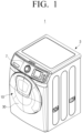
- FIG. 1 is a perspective view illustrating a drum washing machine according to an embodiment of the present disclosure
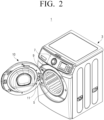
- FIG. 2 is a perspective view illustrating a state in which a door of the drum washing machine of FIG. 1 is open.
- a drum washing machine 1 may include a washing machine body 3 and a door 10.
- the washing machine body 3 forms an outer appearance of the drum washing machine 1, and a laundry loading opening 5 through which laundry may be inserted into and removed from the inside of the washing machine body 3 is provided in a front surface of the washing machine body 3.
- a control panel 7 for controlling the drum washing machine 1 is provided at the upper part of the front surface of the washing machine body 3.
- a cylindrical washing tub is provided inside the washing machine body 3, and has an opening toward the laundry loading opening 5.
- the washing tub is formed by a double structure of a stationary tub and a rotary tub 9.
- the stationary tub accommodates washing water necessary for washing, and the rotary tub 9 is rotatably disposed inside the stationary to perform washing.
- a water supply device for supplying the washing water to the stationary tub is provided above the stationary tub.
- a drain device for draining the washing water from the stationary tub is provided below the stationary tub.
- the rotary tub 9 includes an opening formed at a position corresponding to the laundry loading opening 5 of the washing machine body 3 on the front surface thereof and a plurality of through holes formed in the surface of the rotary tub 9. Also, a plurality of lifts capable of lifting the laundry are provided on the inner surface of the rotary tub 9.
- the rotary tub 9 may be configured to be rotated on the horizontal axis by a driving device provided on the rear surface thereof.
- the door 10 is provided on the front surface of the washing machine body 3 to open and close the laundry loading opening 5 of the washing machine body 3.
- FIG. 3 is a perspective view illustrating a door for a drum washing machine according to an embodiment of the present disclosure
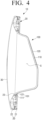
- FIG. 4 is a cross-sectional view illustrating the door for a drum washing machine of FIG. 3 taken along a line I-I.
- the door 10 for a drum washing machine may include a door frame 20 and an inner door assembly 100.
- the door frame 20 supports the inner door assembly 100, and is exposed to the outside when the door 10 closes the laundry loading opening 5 of the washing machine body 3.
- the door frame 20 is formed in a donut shape, and has a fixing hole 23 which the inner door assembly 100 is inserted into and fixed to at the center thereof.
- the door frame 20 may be formed of two frame members, that is, a first frame member 21 and a second frame member 22 to fix the inner door assembly 100.
- the inner door assembly 100 is fixed to the door frame 20.
- a rim portion 101 of the inner door assembly 100 is fixed between the first and second frame members 21 and 22.
- the door frame 20 is disposed by a hinge 11 at one side of the laundry loading opening 5 on the front surface of the washing machine body 3. Accordingly, the inner door assembly 100 fixed to the door frame 20 may open and close the laundry loading opening 5.
- the door frame 20 may be provided with a protective cover 30 for blocking the fixing hole 23. Accordingly, the protective cover 30 closes an inner space S of the inner door assembly 100 fixed to the door frame 20.
- the inner door assembly 100 may be formed in a shape projecting from the door frame 20, and may be inserted into the laundry loading opening 5 of the washing machine body 3.
- the inner door assembly 100 may be formed in a bowl shape.
- FIG. 5 is a perspective view illustrating an inner door assembly for a drum washing machine according to an embodiment of the present disclosure.
- FIG. 6 is an exploded perspective view illustrating the inner door assembly for a drum washing machine of FIG. 5
- FIG. 7 is a cross-sectional view illustrating the inner door assembly for a drum washing machine of FIG. 5 taken along a line II-II.
- an inner door assembly 100 may include an inner door internal shell 110 and an inner door external shell 120.
- the inner door internal shell 110 may include a rim portion 111 of a substantially ring shape and a projecting portion 113 projecting from the rim portion 111 at a certain angle.
- the projecting portion 113 may be formed in a bowl shape having a bottom. Therefore, a space is formed inside the inner door internal shell 110.
- the projecting portion 113 may be formed to extend at a certain angle from the inner circumferential surface of the ring-shaped rim portion 111.
- the projecting portion 113 may be formed to have an obtuse angle with respect to the rim portion 111.
- the projecting portion 113 of the inner door internal shell 110 is positioned inside the washing machine body 3 when the door 10 covers the laundry loading opening 5 of the washing machine body 3.
- the inner door internal shell 110 may be formed by injection molding of plastic.
- the inner door internal shell 110 may be formed of plastic that is easy to injection-mold with an injection machine.
- the inner door external shell 120 may be formed in a shape corresponding to the inner door internal shell 110.
- the inner door external shell 120 may include a rim portion 121 and a projecting portion 123 corresponding to the rim portion 111 and the projecting portion 113 of the inner door internal shell 110 as described above.
- the rim portion 121 of the inner door external shell 120 is formed in a substantially ring shape
- the projecting portion 123 is formed in a shape extending from the inner circumferential surface of the rim portion 121 at a certain angle.
- the projecting portion 123 of the inner door external shell 120 may be formed in a bowl shape corresponding to the projecting portion 113 of the inner door internal shell 110.
- the rim portion 121 and the projecting portion 123 of the inner door external shell 120 may be formed to have a larger dimension than those of the inner door internal shell 110 to accommodate the inner door internal shell 110 inside the inner door external shell 120. As illustrated in FIG. 7 , the inner door external shell 120 may be formed so that the inner surface of the inner door external shell 120 is in contact with or adjacent to the outer surface of the inner door internal shell 110.
- the inner door external shell 120 may be formed by press processing with a metal.
- the inner door external shell 120 may be formed of the same stainless steel as the stationary tub and the rotary tub 9 disposed inside the washing machine body 3.
- the inner door external shell 120 may be formed of a corrosion-resistant material that is not corroded by washing water with detergent, and has a strength capable of withstanding impacts during washing.
- the inner door external shell 120 is disposed on the outside of the inner door internal shell 110, and is combined not to be separated from the inner door internal shell 110. Accordingly, the inner door external shell 120 and the inner door internal shell 110 may be combined in various ways.
- the inner door external shell 120 and the inner door internal shell 110 may be combined by a curling process.
- a curling process for combining an inner door external shell and an inner door internal shell will be described with reference to FIGS. 8A and 8B .
- FIG. 8A is a plan view illustrating a state before a curling process is performed on an inner door assembly for a drum washing machine according to an embodiment of the present disclosure
- FIG. 8B is a plan view illustrating a state in which the curling process of an inner door assembly for a drum washing machine according to an embodiment of the present disclosure is completed.
- a curling portion 122 is provided at the rim portion 121 of the inner door external shell 120 for curling combination.
- the curling portion 122 is formed to extend outward from the rim portion 121 of the inner door external shell 120, and has a size that can wrap the rim portion 111 of the inner door internal shell 110. Accordingly, when the inner door internal shell 110 is inserted into the inner door external shell 120, as illustrated in FIG. 8A , the curling portion 122 of the inner door external shell 120 is projected outward the rim portion 111 of the inner door internal shell 110.
- the rim portion 111 of the inner door internal shell 110 is wrapped by the curling portion 122 of the inner door external shell 120 as illustrated in FIG. 8B .
- the curling portion 122 of the inner door external shell 120 is fixed to the rim portion 111 of the inner door internal shell 110. Accordingly, when the curling process is completed, the inner door external shell 120 and the inner door internal shell 110 are integrally combined and are not separated from each other.
- a plurality of fixing protrusions 116 may be provided at the rim portion 111 of the inner door internal shell 110, and a plurality of fixing grooves 126 into which the plurality of fixing protrusions 116 are inserted may be provided at the rim portion 121 of the inner door external shell 120.
- the plurality of fixing protrusions 116 are formed on the rear surface of the rim portion 111 of the inner door internal shell 110, that is, on one surface of the rim portion 111 of the inner door internal shell 110 in contact with the rim portion 121 of the inner door external shell 120.
- the fixing protrusions 116 are formed in a bar shape and bent at a curvature corresponding to the rim portion 111 of a ring shape, respectively.
- the fixing grooves 126 of the inner door external shell 120 may be formed in a substantially rectangular shape corresponding to the fixing protrusions 116 of the inner door internal shell 110. Accordingly, when the plurality of fixing protrusions 116 of the inner door internal shell 110 are inserted into the plurality of fixing grooves 126 of the inner door external shell 120, the inner door internal shell 110 is not rotated with respect to the inner door external shell 120.
- the curling portion 122 is not provided at portions where the plurality of fixing grooves 126 of the inner door external shell 120 are formed. Accordingly, the curling portion 122 provided on the inner door external shell 120 may be formed in a plurality of portions divided by the plurality of fixing grooves 126.
- the inner door external shell 120 formed of metal may function to reinforce the strength
- the inner door internal shell 110 formed of plastic may serve to apply various designs to the door 10 of the drum washing machine 1.
- the inner door external shell 120 of the inner door assembly 100 made of metal is exposed to the inside of the washing machine body 3. Therefore, even when an impact is applied to the inner door assembly 100 during washing, the inner door external shell 120 made of metal may sufficiently withstand the impact.
- the inner door internal shell 110 is formed of plastic, the inner door internal shell 110 may be formed in various shapes because it has excellent processability unlike the glass used for the conventional door for the drum washing machine.
- the outer surface of the inner door internal shell 110 and the inner surface of the inner door external shell 120 are in contact with or close to each other in the above description, a space may be provided between the inner door internal shell 110 and the inner door external shell 120.
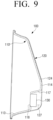
- FIG. 9 is a cross-sectional view illustrating an inner door assembly for a drum washing machine according to another embodiment of the present disclosure.
- the inner door internal shell 110' is formed such that the upper surface 114 of the projecting portion 113 is stepped.
- a step portion 117 lower than the height of the upper surface 114 is provided below the upper surface 114 of the inner door internal shell 110 toward the rim portion 111.
- the rim portion 111 and the remaining portion of the projecting portion 113 of the inner door internal shell 110 are formed to be in contact with the inner door external shell 120 in the same as the inner door internal shell 110 of the above-described embodiment.
- a space 127 is provided between the upper surface 114 of the projecting portion 113 of the inner door internal shell 110' and the upper surface 124 of the projecting portion 123 of the inner door external shell 120.
- a display unit 130 may be disposed in the space 127.
- the step portion 117 of the inner door internal shell 110' is provided with a through hole 118 through which a screen of the display unit 130 is exposed, and the display unit 130 may be accommodated in the space 127.
- electric wires for supplying signals and electricity required for the display unit 130 may be extended to the outside through between the inner door internal shell 110' and the inner door external shell 120, and may be connected to a controller of the drum washing machine 1.
- the display unit 130 is disposed in the space 127 formed between the inner door internal shell 110' and the inner door external shell 120.
- a thing disposed in the space 127 between the inner door internal shell 110' and the inner door external shell 120 is not limited thereto.
- Various devices or parts capable of providing additional functions to the drum washing machine 1 may be disposed in the space 127 between the inner door internal shell 110' and the inner door external shell 120.
- the inner door internal shell 110 and the inner door external shell 120 of the inner door assembly 100 are combined by the curling process; however, a method for combining the inner door internal shell 110 and the inner door external shell 120 is not limited thereto.
- the inner door internal shell 110 and the inner door external shell 120 may be combined in various ways as long as the inner door internal shell 110 and the inner door external shell 120 cannot be separated from each other.
- FIG. 10 is a perspective view illustrating an inner door assembly for a drum washing machine according to another embodiment of the present disclosure
- FIG. 11 is an exploded perspective view illustrating the inner door assembly for a drum washing machine of FIG. 10 .
- an inner door assembly 200 may include an inner door internal shell 210 and an inner door external shell 220.
- the inner door internal shell 210 may include a rim portion 211 and a projecting portion 213 extending from the rim portion 211.
- a plurality of fixing protrusions 216 are provided at a predetermined interval in the rim portion 211 of the inner door internal shell 210.
- the inner door internal shell 210 is the same as or similar to the inner door internal shell 110 according to an embodiment of FIG. 6 ; therefore, a detailed description thereof is omitted.
- the inner door external shell 220 may be formed to receive the inner door internal shell 210, and may include a rim portion 221 and a projecting portion 223 corresponding to the rim portion 211 and the projecting portion 213 of the inner door internal shell 210.
- the rim portion 221 of the inner door external shell 220 is formed in a substantially ring shape
- the projecting portion 223 is formed in a shape extending from the inner circumferential surface of the rim portion 221 at a certain angle with respect to the rim portion 221.
- the projecting portion 223 of the inner door external shell 220 may be formed in a bowl shape corresponding to the projecting portion 213 of the inner door internal shell 210.
- the rim portion 221 and the projecting portion 223 of the inner door external shell 220 may be formed to have a larger dimension than those of the inner door internal shell 210 to accommodate the inner door internal shell 210 in an inner space formed by the projecting portion 223. Accordingly, the inner door external shell 220 may be formed so that the inner surface of the inner door external shell 220 is in contact with or adjacent to the outer surface of the inner door internal shell 210.
- the rim portion 211 of the inner door internal shell 210 may be in contact with the rim portion 221 of the inner door external shell 220, and the outer surface of the projecting portion 213 of the inner door internal shell 210 may be in contact with the inner surface of the projecting portion 223 of the inner door external shell 220.
- the upper surface 214 of the projecting portion 213 of the inner door internal shell 210 and the upper surface 224 of the projecting portion 223 of the inner door external shell 220 may be in contact with each other.
- the rim portion 221 of the inner door external shell 220 may be provided with a plurality of fixing grooves 226 into which the plurality of fixing protrusions 216 provided at the inner door internal shell 210 are inserted.
- the outer circumferential surface of the rim portion 221 of the inner door external shell 220 is provided with the plurality of fixing grooves 226 which may be coupled to the plurality of fixing protrusions 216 formed on a rear surface of the rim portion 211 of the inner door internal shell 210, that is, one surface of the rim portion 211 of the inner door internal shell 210 in contact with the rim portion 221 of the inner door external shell 220.
- the fixing grooves 226 are formed in a substantially bent rectangular shape corresponding to the fixing protrusion 216. Accordingly, when the plurality of fixing protrusions 216 of the inner door internal shell 210 are inserted into the plurality of fixing grooves 226 of the inner door external shell 220, the inner door internal shell 210 is fixed to the inner door external shell 220. Accordingly, the inner door internal shell 210 is not easily separated from the inner door external shell 220, and is not rotated with respect to the inner door external shell 220. Further, in order to increase the combining force between the inner door internal shell 210 and the inner door external shell 220, an adhesive may be applied between the inner door external shell 220 and the inner door internal shell 210.
- the inner door internal shell 210 and the inner door external shell 220 may be combined using screws.
- the inner door assemblies 100 and 200 have no through holes.
- a through hole may be formed in the inner door assembly so that laundry inside the washing machine body 3 can be seen.
- FIG. 12 is a perspective view illustrating an inner door assembly for a drum washing machine according to another embodiment of the present disclosure
- FIG. 13 is an exploded perspective view illustrating the inner door assembly for a drum washing machine of FIG. 12
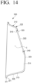
- FIG. 14 is a cross-sectional view illustrating the inner door assembly for a drum washing machine of FIG. 12 taken along a line III-III.
- an inner door assembly 300 may include an inner door internal shell 310 and an inner door external shell 320.
- the inner door internal shell 310 may include a rim portion 311 of a substantially ring shape and a projecting portion 313 projecting from the rim portion 311.
- the projecting portion 313 may be formed in a bowl shape having a bottom. Therefore, a space is formed inside the inner door internal shell 310.
- the projecting portion 313 may be formed to extend at a certain angle from the inner circumferential surface of the ring-shaped rim portion 311. Accordingly, when the door 10 for the drum washing machine covers the laundry loading opening 5 of the washing machine body 3, the projecting portion 313 is positioned inside the washing machine body 3.
- the upper surface 314 of the projecting portion 313 may be provided with a first opening 315 penetrating the upper surface 314 of the projecting portion 313.
- the shape of the first opening 315 may be formed in various shapes depending on its use.
- a plurality of fixing protrusions 316 may be provided at the rim portion 311 of the inner door internal shell 310.
- the plurality of fixing protrusions 316 may be formed on a rear surface of the rim portion 311 of the inner door internal shell 310, that is, on one surface of the rim portion 311 of the inner door internal shell 310 in contact with a rim portion 321 of the inner door external shell 320.
- Each of the fixing protrusions 116 may be formed in a bar shape bent at a curvature corresponding to the rim portion 311 of a ring shape.
- the inner door internal shell 310 may be formed by injection molding of plastic having good moldability.
- the inner door external shell 320 may be formed in a shape corresponding to the inner door internal shell 310.
- the inner door external shell 320 may include the rim portion 321 and a projecting portion 323 corresponding to the rim portion 311 and the projecting portion 313 of the inner door internal shell 310 as described above.
- the rim portion 321 of the inner door external shell 320 is formed in a substantially ring shape
- the projecting portion 323 is formed in a shape extending from the inner circumferential surface of the rim portion 321 at a certain angle with respect to the rim portion 321.
- the projecting portion 323 of the inner door external shell 320 may be formed in a bowl shape corresponding to the projecting portion 313 of the inner door internal shell 310.
- the rim portion 321 and the projecting portion 323 of the inner door external shell 320 may be formed to have a larger dimension than those of the inner door internal shell 310 to accommodate the inner door internal shell 310 in an inner space thereof. As illustrated in FIG. 14 , the inner door external shell 320 may be formed so that the inner surface of the inner door external shell 320 is in contact with or adjacent to the outer surface of the inner door internal shell 310.
- the projecting portion 323 of the inner door external shell 320 may be provided with a second opening 325 formed in a shape corresponding to the first opening 315 of the inner door internal shell 310. Accordingly, when the inner door external shell 320 and the inner door internal shell 310 are combined, the first opening 315 and the second opening 325 are in a fluid communication with each other. Therefore, the projecting portion 323 of the inner door assembly 300 is provided with an opening 301 in fluid communication with the inner space S of the inner door assembly 300 and the outside.
- the rim portion 321 of the inner door external shell 320 may be provided with a plurality of fixing grooves 326 into which a plurality of fixing protrusions 316 provided at the inner door internal shell 310 are inserted.
- the outer circumferential surface of the rim portion 321 of the inner door external shell 320 is provided with the plurality of fixing grooves 326 into which the plurality of fixing protrusions 316 formed on a rear surface of the rim portion 311 of the inner door internal shell 310, that is, one surface of the rim portion 311 of the inner door internal shell 310 in contact with the rim portion 321 of the inner door external shell 320 can be inserted.
- the fixing protrusions 316 of the inner door internal shell 310 are formed in a bent bar shape
- the fixing grooves 326 of the inner door external shell 320 are formed in a substantially bent rectangular groove shape corresponding to the fixing protrusions 316 of the inner door internal shell 310, respectively. Accordingly, when the plurality of fixing protrusions 316 of the inner door internal shell 310 are inserted into the plurality of fixing grooves 326 of the inner door external shell 320, the inner door internal shell 310 is not rotated with respect to the inner door external shell 320.
- the inner door external shell 320 may be formed by pressing a metal, for example, stainless steel.
- the inner door internal shell 310 is inserted into the inner door external shell 320, and is combined with the inner door external shell 320 so that the inner door internal shell 310 is not separated from the inner door external shell 320.
- the inner door external shell 320 and the inner door internal shell 310 may be combined by the curling process.
- a curling portion 322 may be provided at the rim portion 321 of the inner door external shell 320 when the inner door external shell 320 and the inner door internal shell 310 are combined by the curling process.
- the structure of the curling portion 322 is the same as or similar to that of the curling portion 122 of the inner door external shell 120 of the inner door assembly 100 according to the above-described embodiment; therefore, a detailed description thereof is omitted.
- a curling portion 328 may be provided around the second opening 325 for the combination of the first opening 315 and the second opening 325.
- the curling portion 328 may be formed to wrap a circumference of the first opening 315 of the inner door internal shell 310.
- a transparent member 330 may be provided between the first opening 315 of the inner door internal shell 310 and the second opening 325 of the inner door external shell 320.
- a seal 340 may be provided around the transparent member 330 to prevent the washing water of the washing machine body 3 from entering the space S of the inner door assembly 300.
- the transparent member 330 may be formed of transparent glass or transparent plastic. Accordingly, the user may check the laundry contained in the washing machine body 3 through the transparent member 330 provided in the inner door assembly 300.
- the opening 301 formed in the inner door assembly 300 is used as an inspection window for checking the laundry.
- the use of the opening 301 is not limited thereto.
- the opening of the inner door assembly may be used as an additional laundry loading path through which additional laundry may be introduced.
- FIG. 15 is a cross-sectional view illustrating a door for a drum washing machine according to another embodiment of the present disclosure.
- a door 10' for a drum washing machine may include a door frame 40 and an inner door assembly 400.
- the door frame 40 supports the inner door assembly 400, and is exposed to the outside when the door 10' closes the laundry loading opening 5 of the washing machine body 3.
- the door frame 40 may be formed in a donut shape, and have a fixing hole 43 which the inner door assembly 400 is inserted into and fixed to at the center thereof.
- the door frame 40 may be formed of two frame members, that is, a first frame member 41 and a second frame member 42 to fix the inner door assembly 400. When the inner door assembly 400 is inserted into the fixing hole 43 of the first frame member 41 and the second frame member 42 is coupled to the first frame member 42, a rim portion 401 of the inner door assembly 400 is fixed by the first and second frame members 41 and 42.
- the door frame 40 is hinge-connected at one side of the laundry loading opening 5 on the front surface of the washing machine body 3. Accordingly, the inner door assembly 400 fixed to the door frame 40 may open and close the laundry loading opening 5.
- the door frame 40 may be provided with a protective cover 50 for covering the fixing hole 43.
- the inner door assembly 400 is formed in a shape projecting from the door frame 40, and may be inserted into the laundry loading opening 5 of the washing machine body 3.
- the inner door assembly 400 may include an inner door internal shell 410 and an inner door external shell 420.
- the inner door internal shell 410 may include a rim portion 411 of a substantially ring shape and a projecting portion 413 projecting from the rim portion 411.
- the projecting portion 413 may be formed in a bowl shape having a bottom. Therefore, a space S is formed inside the inner door internal shell 410.
- the projecting portion 413 of the inner door internal shell 410 may be formed in a shape to extend at a certain angle, for example, at an obtuse angle from the inner circumferential surface of the ring-shaped rim portion 411.
- the upper surface 414 of the projecting portion 413 of the inner door internal shell 410 is provided with a first opening 415 passing through the upper surface 414 of the projecting portion 413, and an additional laundry loading passage 430 is provided to extend from the first opening 415 toward the rim portion 411.
- the cross-section of the additional laundry loading passage 430 may be formed in a substantially rectangular shape.
- a plurality of fixing protrusions may be provided on the rim portion 411 of the inner door internal shell 410 in the same manner as the inner door internal shell 110 according to the above-described embodiment.
- the plurality of fixing protrusions may be formed on a rear surface of the rim portion 411 of the inner door internal shell 410, that is, on one surface of the rim portion 411 of the inner door internal shell 410 in contact with a rim portion 421 of the inner door external shell 420.
- the inner door internal shell 410 may be formed by injection molding of a plastic having good injection properties.
- the inner door external shell 420 may be formed in a shape corresponding to the inner door internal shell 410.
- the inner door external shell 420 may include the rim portion 421 and a projecting portion 423 corresponding to the rim portion 411 and the projecting portion 413 of the inner door internal shell 410 as described above.
- the rim portion 421 of the inner door external shell 420 is formed in a substantially ring shape
- the projecting portion 423 is formed in a shape extending from the inner circumferential surface of the rim portion 421 at a certain angle.
- the projecting portion 423 of the inner door external shell 420 may be formed in a bowl shape corresponding to the projecting portion 413 of the inner door internal shell 410.
- the rim portion 421 and the projecting portion 423 of the inner door external shell 420 may be formed to have a larger dimension than those of the inner door internal shell 410 to accommodate the inner door internal shell 410 therein. As illustrated in FIG. 15 , the inner door external shell 420 may be formed so that the inner surface of the inner door external shell 420 is in contact with or adjacent to the outer surface of the inner door internal shell 410.
- the projecting portion 423 of the inner door external shell 420 may be provided with a second opening 425 formed in a shape corresponding to the first opening 415 of the inner door internal shell 410. Accordingly, when the inner door external shell 420 and the inner door internal shell 410 are combined, the first opening 415 and the second opening 425 are in fluid communication with each other. Therefore, the additional laundry loading passage 430 extending from the first opening 415 of the inner door internal shell 410 is in fluid communication with the outside of the inner door assembly 400 through the second opening 425 of the inner door external shell 420. Accordingly, the user can further add laundry into the washing machine body 3 by using the additional laundry loading passage 430 of the inner door assembly 400.
- the rim portion 421 of the inner door external shell 420 may be provided with a plurality of fixing grooves into which a plurality of fixing protrusions provided at the inner door internal shell 410 are inserted in the same manner as the inner door external shell 120 according to the above-described embodiment.
- the outer circumferential surface of the rim portion 421 of the inner door external shell 420 may be provided with the plurality of fixing grooves into which the plurality of fixing protrusions formed on a rear surface of the rim portion 411 of the inner door internal shell 410, that is, one surface of the rim portion 411 of the inner door internal shell 410 in contact with the rim portion 421 of the inner door external shell 420 are inserted.
- the inner door internal shell 410 is fixed to and is not rotated with respect to the inner door external shell 420.
- the inner door external shell 420 may be formed by pressing a metal, for example, stainless steel.
- the inner door internal shell 410 is inserted into the inner door external shell 420, and is combined with the inner door external shell 420 so that the inner door internal shell 410 is not separated from the inner door external shell 420.
- the inner door external shell 320 and the inner door internal shell 310 may be combined by the curling process.
- the protective cover 50 provided on the door 10' for the drum washing machine may be provided with a lid 60 for opening and closing the additional laundry loading passage 430 as described above.
- the lid 60 is coupled to the protective cover 30 by a hinge, thereby opening and closing the additional laundry loading passage 430 of the inner door assembly 400.
- the inner door assembly 400 is located inside the washing machine body 3. Therefore, if necessary, the user may open the lid 60 provided on the protective cover 30, and then further introduce laundry into the washing machine body 3 by using the additional laundry loading passage 430 while the door 10' for the drum washing machine is closing the laundry loading opening 5.
- the additional laundry loading passage 430 is injection-molded integrally with the inner door internal shell 410; however, the structure of the additional laundry loading passage 430 is not limited thereto. As another example, although not illustrated, an additional laundry loading passage may be formed separately from the inner door internal shell 410, and then coupled to the inner door internal shell 410.
- the inner door assembly according to an embodiment of the present disclosure as described above may be manufactured by the following method.
- plastic is injected by an injection machine or an injection device to produce an inner door internal shell.
- an inner door external shell is manufactured by a separated process.
- the inner door external shell may be formed by pressing a metal having corrosion resistance and rigidity, for example, stainless steel.
- the inner door internal shell and the inner door external shell may be combined by various methods.
- the inner door internal shell and the inner door external shell may be combined and fixed by a curling process.
- the inner door external shell is provided with a curling portion for combination between the inner door internal shell and the inner door external shell.
Landscapes
- Engineering & Computer Science (AREA)
- Textile Engineering (AREA)
- Civil Engineering (AREA)
- Structural Engineering (AREA)
- Main Body Construction Of Washing Machines And Laundry Dryers (AREA)
Claims (14)
- Eine Innentüranordnung (100) für eine Trommelwaschmaschine (1), die Folgendes umfasst:eine Innentür-Innenschale (110), die aus Kunststoff ausgebildet ist und einen Randabschnitt (111) und einen von dem Randabschnitt (111) vorstehenden Abschnitt (113) aufweist; undeine Innentür-Außenschale (120), die aus Metall ausgebildet ist und einen Randabschnitt (121) und einen vorstehenden Abschnitt (123) aufweist, der dem Randabschnitt (111) und dem vorstehenden Abschnitt (113) der Innentür-Innenschale (110) entspricht,dadurch gekennzeichnet, dassdie Innentür-Innenschale (110) getrennt von der Innentür-Außenschale (120) ausgebildet, in die Innentür-Außenschale (120) eingesetzt und so kombiniert ist, dass sie nicht von der Innentür-Außenschale (120) getrennt werden kann.
- Die Innentüranordnung (100) für die Trommelwaschmaschine nach Anspruch 1, wobei:der Randabschnitt (121) der Innentür-Außenschale (120) ferner einen Einrollabschnitt (122)
aufweist, undder Einrollabschnitt (122) der Innentür-Außenschale (120) an dem Randabschnitt (111) der Innentür-Innenschale (110) durch einen Einrollvorgang befestigt ist. - Die Innentüranordnung (100) für die Trommelwaschmaschine nach Anspruch 1, wobei:der Randabschnitt (111) der Innentür-Innenschale (110) mit einer Vielzahl von Befestigungsvorsprüngen (116) versehen ist, undder Randabschnitt (121) der Innentür-Außenschale (120) mit einer Vielzahl von Befestigungsnuten (126) versehen ist, in die die Vielzahl von Befestigungsvorsprüngen (116) eingesetzt ist.
- Die Innentüranordnung (100) für die Trommelwaschmaschine nach Anspruch 1, wobei:der vorstehende Abschnitt (113) der Innentür-Innenschale (110) mit einer ersten Öffnung (315) versehen ist, undder vorstehende Abschnitt (123) der Innentür-Außenschale (120) mit einer zweiten Öffnung (325) versehen ist, die der ersten Öffnung (315) entspricht.
- Die Innentüranordnung (100) für die Trommelwaschmaschine nach Anspruch 4, wobei diezweite Öffnung (325) der Innentür-Außenschale (120) mit einem Einrollabschnitt (122) versehen ist, der einen Umfang der ersten Öffnung (315) der Innentür-Innenschale (110) umhüllt.
- Die Innentüranordnung (100) für die Trommelwaschmaschine nach Anspruch 1, wobei die Innentür-Innenschale (110) durch ein Spritzverfahren ausgebildet ist.
- Die Innentüranordnung (100) für die Trommelwaschmaschine nach Anspruch 6, wobei die Innentür-Außenschale (120) aus rostfreiem Stahl ausgebildet ist.
- Die Innentüranordnung (100) für die Trommelwaschmaschine nach Anspruch 7, wobei die Innentür-Außenschale (120) durch ein Pressverfahren ausgebildet ist.
- Eine Tür (10) für eine Trommelwaschmaschine (1), umfassend:eine Innentüranordnung (100) nach einem der Ansprüche 1 bis 8, die in eine Wäscheeinlegeöffnung (5) der Trommelwaschmaschine (1) eingesetzt ist; undeinen Türrahmen (40), derein Befestigungsloch (43) umfasst, in das die Innentüranordnung (100) eingesetzt ist, und der in der Trommelwaschmaschine (1) angeordnet ist, so dass die Innentüranordnung (100) die Wäscheeinlegeöffnung (5) der Trommelwaschmaschine (1) öffnet und schließt.
- Die Tür (10) für die Trommelwaschmaschine nach Anspruch 9, wenn abhängig von Anspruch 4, wobei ein zusätzlicher, mit der ersten Öffnung (315) verbundener Wäscheeinlegeekanal (430) innerhalb des vorstehenden Abschnitts (113) der Innentür-Innenschale (110) vorgesehen ist.
- Die Tür (10) für die Trommelwaschmaschine von 10, wobei eine Lippe an einem Ende des zusätzlichen Wäscheeinlegekanals (430) vorgesehen ist.
- Die Tür (10) für die Trommelwaschmaschine nach Anspruch 9, wobei der Türrahmen (40) ferner eine Schutzabdeckung (30) zum Verschließen des Befestigungslochs (43) aufweist.
- Eine Trommelwaschmaschine (1), umfassend:einen Waschmaschinenkörper (3), der eine Wäscheeinlegeöffnung (5) umfasst, in die Wäsche eingefüllt wird; undeine Tür (10) nach einem der Ansprüche 9 bis 12, die im Waschmaschinenkörper (3) angeordnet ist, um die Wäscheeinlegeöffnung (5) zu öffnen und zu schließen.
- Ein Verfahren zur Herstellung einer Innentüranordnung (100) für eine Trommelwaschmaschine (1), wobei das Verfahren umfasst:- Ausbilden einer Innentür-Innenschale (110), die aus Kunststoff hergestellt ist und einen Randabschnitt (111) und einen vorstehenden Abschnitt (113), der von dem Randabschnitt (111) vorsteht, enthält, durch ein Spritzverfahren;gekennzeichnet durch- separates Ausbilden einer Innentür-Außenschale (120), die aus Metall besteht und einen Randabschnitt (121) und einen vorstehenden Abschnitt (123) aufweist, der dem Randabschnitt (111) und dem vorstehenden Abschnitt (113) der Innentür-Innenschale (110) entspricht, durch ein Pressverfahren;- Einsetzen der Innentür-Innenschale (110) in die Innentür-Außenschale (120) und Befestigen der Innentür-Innenschale (110) an der Innentür-Außenschale (120), wobei die Innentür-Außenschale (120) so kombiniert ist, dass sie nicht von der Innentür-Innenschale (110) getrennt ist.
Applications Claiming Priority (1)
| Application Number | Priority Date | Filing Date | Title |
|---|---|---|---|
| KR1020160064993A KR102271280B1 (ko) | 2016-05-26 | 2016-05-26 | 드럼 세탁기용 내부 도어 조립체, 도어, 및 이를 구비한 드럼 세탁기 |
Publications (2)
| Publication Number | Publication Date |
|---|---|
| EP3249092A1 EP3249092A1 (de) | 2017-11-29 |
| EP3249092B1 true EP3249092B1 (de) | 2023-04-05 |
Family
ID=58159008
Family Applications (1)
| Application Number | Title | Priority Date | Filing Date |
|---|---|---|---|
| EP17157908.9A Active EP3249092B1 (de) | 2016-05-26 | 2017-02-24 | Inneretüranordnung für eine trommelwaschmaschine und trommelwaschmaschine damit |
Country Status (3)
| Country | Link |
|---|---|
| US (1) | US10961650B2 (de) |
| EP (1) | EP3249092B1 (de) |
| KR (1) | KR102271280B1 (de) |
Families Citing this family (5)
| Publication number | Priority date | Publication date | Assignee | Title |
|---|---|---|---|---|
| KR20160103888A (ko) | 2015-02-25 | 2016-09-02 | 삼성전자주식회사 | 세탁기 |
| KR102568675B1 (ko) * | 2017-02-21 | 2023-08-22 | 엘지전자 주식회사 | 의류처리장치 |
| DE102018210860A1 (de) | 2018-07-02 | 2020-01-02 | BSH Hausgeräte GmbH | Wäschepflegegerät mit einer Gerätetür |
| CN110872753A (zh) * | 2018-08-31 | 2020-03-10 | 无锡小天鹅电器有限公司 | 衣物处理设备及其门盖组件 |
| US11346039B2 (en) | 2019-05-08 | 2022-05-31 | Whirlpool Corporation | Door assembly for a laundry treating appliance |
Family Cites Families (14)
| Publication number | Priority date | Publication date | Assignee | Title |
|---|---|---|---|---|
| DE4304009C2 (de) * | 1993-02-11 | 1999-07-01 | Miele & Cie | Wäschebehandlungsgerät |
| DE10031171A1 (de) | 2000-06-27 | 2002-01-10 | Bsh Bosch Siemens Hausgeraete | Bullaugen-Fenster für eine Frontlader-Trommelwaschmaschine |
| KR100595180B1 (ko) | 2002-07-31 | 2006-07-03 | 엘지전자 주식회사 | 빨래건조기/드럼세탁기의 도어 |
| US7478502B2 (en) | 2003-08-14 | 2009-01-20 | Gemtron Corporation | Appliance doors |
| KR20050108614A (ko) | 2004-05-12 | 2005-11-17 | 주식회사 대우일렉트로닉스 | 원적외선을 발생하는 도어를 구비한 드럼 세탁기 |
| KR101125402B1 (ko) | 2004-07-19 | 2012-03-27 | 엘지전자 주식회사 | 드럼 세탁기의 도어 구조 |
| US7690226B2 (en) * | 2005-06-09 | 2010-04-06 | Lg Electronics Inc. | Washing machine and method for manufacturing door thereof |
| US20110023559A1 (en) * | 2009-07-30 | 2011-02-03 | Bsh Home Appliances Corporation | Door hinge for a household appliance door |
| DE102009047595A1 (de) * | 2009-12-07 | 2011-06-09 | BSH Bosch und Siemens Hausgeräte GmbH | Tür für ein Hausgerät mit einem Sichtfenster und Verfahren zum Herstellen einer solchen Tür |
| EP2405051B1 (de) * | 2010-07-06 | 2014-07-02 | Electrolux Home Products Corporation N.V. | Glasbullaugenfenster für ein Wasch- und/oder Trocknungsgerät |
| EP2415920B1 (de) * | 2010-08-06 | 2013-05-29 | Fagor, S. Coop. | Waschmaschine mit einer Tür mit einem Hohlraum für eine Ladung |
| KR102147824B1 (ko) * | 2013-09-11 | 2020-08-25 | 삼성전자주식회사 | 세탁기 및 세탁기 도어의 제조방법 |
| ES2564877B1 (es) * | 2014-09-25 | 2017-01-18 | BSH Electrodomésticos España S.A. | Aparato doméstico para el tratamiento de prendas de ropa con una ventana de cristal con revestimiento específico de una puerta |
| KR20160103888A (ko) * | 2015-02-25 | 2016-09-02 | 삼성전자주식회사 | 세탁기 |
-
2016
- 2016-05-26 KR KR1020160064993A patent/KR102271280B1/ko active IP Right Grant
-
2017
- 2017-02-24 EP EP17157908.9A patent/EP3249092B1/de active Active
- 2017-05-22 US US15/601,995 patent/US10961650B2/en active Active
Also Published As
| Publication number | Publication date |
|---|---|
| KR20170133780A (ko) | 2017-12-06 |
| EP3249092A1 (de) | 2017-11-29 |
| US20170342621A1 (en) | 2017-11-30 |
| US10961650B2 (en) | 2021-03-30 |
| KR102271280B1 (ko) | 2021-06-30 |
Similar Documents
| Publication | Publication Date | Title |
|---|---|---|
| EP3249092B1 (de) | Inneretüranordnung für eine trommelwaschmaschine und trommelwaschmaschine damit | |
| EP3189179B1 (de) | Waschmaschine | |
| JP5505237B2 (ja) | ドラム式洗濯機 | |
| JP5618517B2 (ja) | 電気洗濯機 | |
| US7513131B2 (en) | Lid assembly for washing machine | |
| EP2000574B1 (de) | Rotierender Laugenbehälterkörper und Trommelwaschmaschine damit | |
| KR20030060557A (ko) | 드럼세탁기의 도어 | |
| US20050262887A1 (en) | Door assembly for washing machine | |
| EP2754746B1 (de) | Waschmaschine und Verfahren zur Herstellung einer Tür dafür | |
| PL1770198T3 (pl) | Ładowana od góry pralka ze środkami blokującymi pokrywę | |
| AU2017362549B2 (en) | A door assembly for a laundry treatment machine | |
| JP2015144881A (ja) | ドラム式洗濯機およびドラム式洗濯乾燥機 | |
| US20060254319A1 (en) | Washing machine | |
| KR20030062484A (ko) | 드럼 세탁기의 도어 장착구조 | |
| KR20200096042A (ko) | 의류처리장치 | |
| JP5707523B2 (ja) | 電気洗濯機 | |
| JP6177822B2 (ja) | 電気洗濯機 | |
| JP2008054813A (ja) | ドラム式洗濯機 | |
| CN101168902A (zh) | 滚筒洗衣机门的组件 | |
| JP5731035B2 (ja) | ドラム式洗濯機およびドラム式洗濯乾燥機 | |
| RU2615263C2 (ru) | Стиральная машина и способ изготовления ее дверцы | |
| CN210104347U (zh) | 洗衣机的门盖组件及具有其的洗衣机 | |
| JP6295356B2 (ja) | 電気洗濯機 | |
| WO2019129423A1 (en) | A door for a washer/dryer | |
| KR20150011043A (ko) | 세탁기 |
Legal Events
| Date | Code | Title | Description |
|---|---|---|---|
| PUAI | Public reference made under article 153(3) epc to a published international application that has entered the european phase |
Free format text: ORIGINAL CODE: 0009012 |
|
| STAA | Information on the status of an ep patent application or granted ep patent |
Free format text: STATUS: THE APPLICATION HAS BEEN PUBLISHED |
|
| AK | Designated contracting states |
Kind code of ref document: A1 Designated state(s): AL AT BE BG CH CY CZ DE DK EE ES FI FR GB GR HR HU IE IS IT LI LT LU LV MC MK MT NL NO PL PT RO RS SE SI SK SM TR |
|
| AX | Request for extension of the european patent |
Extension state: BA ME |
|
| STAA | Information on the status of an ep patent application or granted ep patent |
Free format text: STATUS: REQUEST FOR EXAMINATION WAS MADE |
|
| 17P | Request for examination filed |
Effective date: 20180103 |
|
| RBV | Designated contracting states (corrected) |
Designated state(s): AL AT BE BG CH CY CZ DE DK EE ES FI FR GB GR HR HU IE IS IT LI LT LU LV MC MK MT NL NO PL PT RO RS SE SI SK SM TR |
|
| STAA | Information on the status of an ep patent application or granted ep patent |
Free format text: STATUS: EXAMINATION IS IN PROGRESS |
|
| STAA | Information on the status of an ep patent application or granted ep patent |
Free format text: STATUS: EXAMINATION IS IN PROGRESS |
|
| 17Q | First examination report despatched |
Effective date: 20210125 |
|
| STAA | Information on the status of an ep patent application or granted ep patent |
Free format text: STATUS: EXAMINATION IS IN PROGRESS |
|
| GRAP | Despatch of communication of intention to grant a patent |
Free format text: ORIGINAL CODE: EPIDOSNIGR1 |
|
| STAA | Information on the status of an ep patent application or granted ep patent |
Free format text: STATUS: GRANT OF PATENT IS INTENDED |
|
| INTG | Intention to grant announced |
Effective date: 20221222 |
|
| GRAS | Grant fee paid |
Free format text: ORIGINAL CODE: EPIDOSNIGR3 |
|
| GRAA | (expected) grant |
Free format text: ORIGINAL CODE: 0009210 |
|
| STAA | Information on the status of an ep patent application or granted ep patent |
Free format text: STATUS: THE PATENT HAS BEEN GRANTED |
|
| AK | Designated contracting states |
Kind code of ref document: B1 Designated state(s): AL AT BE BG CH CY CZ DE DK EE ES FI FR GB GR HR HU IE IS IT LI LT LU LV MC MK MT NL NO PL PT RO RS SE SI SK SM TR |
|
| REG | Reference to a national code |
Ref country code: GB Ref legal event code: FG4D |
|
| REG | Reference to a national code |
Ref country code: CH Ref legal event code: EP |
|
| REG | Reference to a national code |
Ref country code: AT Ref legal event code: REF Ref document number: 1558330 Country of ref document: AT Kind code of ref document: T Effective date: 20230415 |
|
| REG | Reference to a national code |
Ref country code: DE Ref legal event code: R096 Ref document number: 602017067376 Country of ref document: DE |
|
| REG | Reference to a national code |
Ref country code: IE Ref legal event code: FG4D |
|
| REG | Reference to a national code |
Ref country code: LT Ref legal event code: MG9D |
|
| REG | Reference to a national code |
Ref country code: NL Ref legal event code: MP Effective date: 20230405 |
|
| REG | Reference to a national code |
Ref country code: AT Ref legal event code: MK05 Ref document number: 1558330 Country of ref document: AT Kind code of ref document: T Effective date: 20230405 |
|
| PG25 | Lapsed in a contracting state [announced via postgrant information from national office to epo] |
Ref country code: NL Free format text: LAPSE BECAUSE OF FAILURE TO SUBMIT A TRANSLATION OF THE DESCRIPTION OR TO PAY THE FEE WITHIN THE PRESCRIBED TIME-LIMIT Effective date: 20230405 |
|
| PG25 | Lapsed in a contracting state [announced via postgrant information from national office to epo] |
Ref country code: SE Free format text: LAPSE BECAUSE OF FAILURE TO SUBMIT A TRANSLATION OF THE DESCRIPTION OR TO PAY THE FEE WITHIN THE PRESCRIBED TIME-LIMIT Effective date: 20230405 Ref country code: PT Free format text: LAPSE BECAUSE OF FAILURE TO SUBMIT A TRANSLATION OF THE DESCRIPTION OR TO PAY THE FEE WITHIN THE PRESCRIBED TIME-LIMIT Effective date: 20230807 Ref country code: NO Free format text: LAPSE BECAUSE OF FAILURE TO SUBMIT A TRANSLATION OF THE DESCRIPTION OR TO PAY THE FEE WITHIN THE PRESCRIBED TIME-LIMIT Effective date: 20230705 Ref country code: ES Free format text: LAPSE BECAUSE OF FAILURE TO SUBMIT A TRANSLATION OF THE DESCRIPTION OR TO PAY THE FEE WITHIN THE PRESCRIBED TIME-LIMIT Effective date: 20230405 Ref country code: AT Free format text: LAPSE BECAUSE OF FAILURE TO SUBMIT A TRANSLATION OF THE DESCRIPTION OR TO PAY THE FEE WITHIN THE PRESCRIBED TIME-LIMIT Effective date: 20230405 |
|
| PG25 | Lapsed in a contracting state [announced via postgrant information from national office to epo] |
Ref country code: RS Free format text: LAPSE BECAUSE OF FAILURE TO SUBMIT A TRANSLATION OF THE DESCRIPTION OR TO PAY THE FEE WITHIN THE PRESCRIBED TIME-LIMIT Effective date: 20230405 Ref country code: PL Free format text: LAPSE BECAUSE OF FAILURE TO SUBMIT A TRANSLATION OF THE DESCRIPTION OR TO PAY THE FEE WITHIN THE PRESCRIBED TIME-LIMIT Effective date: 20230405 Ref country code: LV Free format text: LAPSE BECAUSE OF FAILURE TO SUBMIT A TRANSLATION OF THE DESCRIPTION OR TO PAY THE FEE WITHIN THE PRESCRIBED TIME-LIMIT Effective date: 20230405 Ref country code: LT Free format text: LAPSE BECAUSE OF FAILURE TO SUBMIT A TRANSLATION OF THE DESCRIPTION OR TO PAY THE FEE WITHIN THE PRESCRIBED TIME-LIMIT Effective date: 20230405 Ref country code: IS Free format text: LAPSE BECAUSE OF FAILURE TO SUBMIT A TRANSLATION OF THE DESCRIPTION OR TO PAY THE FEE WITHIN THE PRESCRIBED TIME-LIMIT Effective date: 20230805 Ref country code: HR Free format text: LAPSE BECAUSE OF FAILURE TO SUBMIT A TRANSLATION OF THE DESCRIPTION OR TO PAY THE FEE WITHIN THE PRESCRIBED TIME-LIMIT Effective date: 20230405 Ref country code: GR Free format text: LAPSE BECAUSE OF FAILURE TO SUBMIT A TRANSLATION OF THE DESCRIPTION OR TO PAY THE FEE WITHIN THE PRESCRIBED TIME-LIMIT Effective date: 20230706 Ref country code: AL Free format text: LAPSE BECAUSE OF FAILURE TO SUBMIT A TRANSLATION OF THE DESCRIPTION OR TO PAY THE FEE WITHIN THE PRESCRIBED TIME-LIMIT Effective date: 20230405 |
|
| PG25 | Lapsed in a contracting state [announced via postgrant information from national office to epo] |
Ref country code: FI Free format text: LAPSE BECAUSE OF FAILURE TO SUBMIT A TRANSLATION OF THE DESCRIPTION OR TO PAY THE FEE WITHIN THE PRESCRIBED TIME-LIMIT Effective date: 20230405 |
|
| REG | Reference to a national code |
Ref country code: DE Ref legal event code: R097 Ref document number: 602017067376 Country of ref document: DE |
|
| PG25 | Lapsed in a contracting state [announced via postgrant information from national office to epo] |
Ref country code: SK Free format text: LAPSE BECAUSE OF FAILURE TO SUBMIT A TRANSLATION OF THE DESCRIPTION OR TO PAY THE FEE WITHIN THE PRESCRIBED TIME-LIMIT Effective date: 20230405 |
|
| PG25 | Lapsed in a contracting state [announced via postgrant information from national office to epo] |
Ref country code: SM Free format text: LAPSE BECAUSE OF FAILURE TO SUBMIT A TRANSLATION OF THE DESCRIPTION OR TO PAY THE FEE WITHIN THE PRESCRIBED TIME-LIMIT Effective date: 20230405 Ref country code: SK Free format text: LAPSE BECAUSE OF FAILURE TO SUBMIT A TRANSLATION OF THE DESCRIPTION OR TO PAY THE FEE WITHIN THE PRESCRIBED TIME-LIMIT Effective date: 20230405 Ref country code: RO Free format text: LAPSE BECAUSE OF FAILURE TO SUBMIT A TRANSLATION OF THE DESCRIPTION OR TO PAY THE FEE WITHIN THE PRESCRIBED TIME-LIMIT Effective date: 20230405 Ref country code: EE Free format text: LAPSE BECAUSE OF FAILURE TO SUBMIT A TRANSLATION OF THE DESCRIPTION OR TO PAY THE FEE WITHIN THE PRESCRIBED TIME-LIMIT Effective date: 20230405 Ref country code: DK Free format text: LAPSE BECAUSE OF FAILURE TO SUBMIT A TRANSLATION OF THE DESCRIPTION OR TO PAY THE FEE WITHIN THE PRESCRIBED TIME-LIMIT Effective date: 20230405 Ref country code: CZ Free format text: LAPSE BECAUSE OF FAILURE TO SUBMIT A TRANSLATION OF THE DESCRIPTION OR TO PAY THE FEE WITHIN THE PRESCRIBED TIME-LIMIT Effective date: 20230405 |
|
| PLBE | No opposition filed within time limit |
Free format text: ORIGINAL CODE: 0009261 |
|
| STAA | Information on the status of an ep patent application or granted ep patent |
Free format text: STATUS: NO OPPOSITION FILED WITHIN TIME LIMIT |
|
| 26N | No opposition filed |
Effective date: 20240108 |
|
| PGFP | Annual fee paid to national office [announced via postgrant information from national office to epo] |
Ref country code: DE Payment date: 20240122 Year of fee payment: 8 |
|
| PG25 | Lapsed in a contracting state [announced via postgrant information from national office to epo] |
Ref country code: SI Free format text: LAPSE BECAUSE OF FAILURE TO SUBMIT A TRANSLATION OF THE DESCRIPTION OR TO PAY THE FEE WITHIN THE PRESCRIBED TIME-LIMIT Effective date: 20230405 |
|
| PG25 | Lapsed in a contracting state [announced via postgrant information from national office to epo] |
Ref country code: SI Free format text: LAPSE BECAUSE OF FAILURE TO SUBMIT A TRANSLATION OF THE DESCRIPTION OR TO PAY THE FEE WITHIN THE PRESCRIBED TIME-LIMIT Effective date: 20230405 Ref country code: IT Free format text: LAPSE BECAUSE OF FAILURE TO SUBMIT A TRANSLATION OF THE DESCRIPTION OR TO PAY THE FEE WITHIN THE PRESCRIBED TIME-LIMIT Effective date: 20230405 |