EP3249083B1 - Dehnfasertrockenspinnmechanismus und wartungssteuerungsverfahren für spinnanordnung - Google Patents
Dehnfasertrockenspinnmechanismus und wartungssteuerungsverfahren für spinnanordnung Download PDFInfo
- Publication number
- EP3249083B1 EP3249083B1 EP15878407.4A EP15878407A EP3249083B1 EP 3249083 B1 EP3249083 B1 EP 3249083B1 EP 15878407 A EP15878407 A EP 15878407A EP 3249083 B1 EP3249083 B1 EP 3249083B1
- Authority
- EP
- European Patent Office
- Prior art keywords
- spinning
- spinning assembly
- assembly
- spinneret
- slide rail
- Prior art date
- Legal status (The legal status is an assumption and is not a legal conclusion. Google has not performed a legal analysis and makes no representation as to the accuracy of the status listed.)
- Active
Links
- 238000009987 spinning Methods 0.000 title claims description 290
- 230000007246 mechanism Effects 0.000 title claims description 88
- 238000012423 maintenance Methods 0.000 title claims description 63
- 238000000578 dry spinning Methods 0.000 title claims description 44
- 238000000034 method Methods 0.000 title claims description 30
- 239000000835 fiber Substances 0.000 title description 2
- 210000004177 elastic tissue Anatomy 0.000 claims description 51
- 238000013519 translation Methods 0.000 claims description 23
- 230000001174 ascending effect Effects 0.000 claims description 16
- 238000006243 chemical reaction Methods 0.000 claims description 15
- 230000008859 change Effects 0.000 claims description 11
- 238000004519 manufacturing process Methods 0.000 description 26
- 238000004140 cleaning Methods 0.000 description 15
- 229920000642 polymer Polymers 0.000 description 11
- 230000008569 process Effects 0.000 description 10
- 238000000429 assembly Methods 0.000 description 9
- 230000000712 assembly Effects 0.000 description 9
- 230000009467 reduction Effects 0.000 description 6
- 229920002334 Spandex Polymers 0.000 description 5
- 239000003638 chemical reducing agent Substances 0.000 description 5
- 239000004759 spandex Substances 0.000 description 5
- 239000002184 metal Substances 0.000 description 4
- 238000011161 development Methods 0.000 description 3
- 238000010586 diagram Methods 0.000 description 3
- 230000009471 action Effects 0.000 description 2
- 230000008602 contraction Effects 0.000 description 2
- 238000012545 processing Methods 0.000 description 2
- 239000002904 solvent Substances 0.000 description 2
- 238000009825 accumulation Methods 0.000 description 1
- 238000005260 corrosion Methods 0.000 description 1
- 230000007797 corrosion Effects 0.000 description 1
- 238000000354 decomposition reaction Methods 0.000 description 1
- 238000007380 fibre production Methods 0.000 description 1
- 238000001914 filtration Methods 0.000 description 1
- 230000006872 improvement Effects 0.000 description 1
- 239000012535 impurity Substances 0.000 description 1
- 229920006306 polyurethane fiber Polymers 0.000 description 1
- 230000006798 recombination Effects 0.000 description 1
- 238000005215 recombination Methods 0.000 description 1
- 238000000935 solvent evaporation Methods 0.000 description 1
- 230000000087 stabilizing effect Effects 0.000 description 1
- 239000000126 substance Substances 0.000 description 1
- 238000006467 substitution reaction Methods 0.000 description 1
- 230000001360 synchronised effect Effects 0.000 description 1
- 229920002994 synthetic fiber Polymers 0.000 description 1
- 239000012209 synthetic fiber Substances 0.000 description 1
- 238000012546 transfer Methods 0.000 description 1
Images

Classifications
-
- D—TEXTILES; PAPER
- D01—NATURAL OR MAN-MADE THREADS OR FIBRES; SPINNING
- D01D—MECHANICAL METHODS OR APPARATUS IN THE MANUFACTURE OF ARTIFICIAL FILAMENTS, THREADS, FIBRES, BRISTLES OR RIBBONS
- D01D11/00—Other features of manufacture
-
- D—TEXTILES; PAPER
- D01—NATURAL OR MAN-MADE THREADS OR FIBRES; SPINNING
- D01D—MECHANICAL METHODS OR APPARATUS IN THE MANUFACTURE OF ARTIFICIAL FILAMENTS, THREADS, FIBRES, BRISTLES OR RIBBONS
- D01D4/00—Spinnerette packs; Cleaning thereof
-
- D—TEXTILES; PAPER
- D01—NATURAL OR MAN-MADE THREADS OR FIBRES; SPINNING
- D01D—MECHANICAL METHODS OR APPARATUS IN THE MANUFACTURE OF ARTIFICIAL FILAMENTS, THREADS, FIBRES, BRISTLES OR RIBBONS
- D01D4/00—Spinnerette packs; Cleaning thereof
- D01D4/02—Spinnerettes
-
- D—TEXTILES; PAPER
- D01—NATURAL OR MAN-MADE THREADS OR FIBRES; SPINNING
- D01D—MECHANICAL METHODS OR APPARATUS IN THE MANUFACTURE OF ARTIFICIAL FILAMENTS, THREADS, FIBRES, BRISTLES OR RIBBONS
- D01D4/00—Spinnerette packs; Cleaning thereof
- D01D4/08—Supporting spinnerettes or other parts of spinnerette packs
-
- D—TEXTILES; PAPER
- D01—NATURAL OR MAN-MADE THREADS OR FIBRES; SPINNING
- D01D—MECHANICAL METHODS OR APPARATUS IN THE MANUFACTURE OF ARTIFICIAL FILAMENTS, THREADS, FIBRES, BRISTLES OR RIBBONS
- D01D5/00—Formation of filaments, threads, or the like
- D01D5/04—Dry spinning methods
-
- D—TEXTILES; PAPER
- D01—NATURAL OR MAN-MADE THREADS OR FIBRES; SPINNING
- D01D—MECHANICAL METHODS OR APPARATUS IN THE MANUFACTURE OF ARTIFICIAL FILAMENTS, THREADS, FIBRES, BRISTLES OR RIBBONS
- D01D5/00—Formation of filaments, threads, or the like
- D01D5/18—Formation of filaments, threads, or the like by means of rotating spinnerets
-
- D—TEXTILES; PAPER
- D01—NATURAL OR MAN-MADE THREADS OR FIBRES; SPINNING
- D01D—MECHANICAL METHODS OR APPARATUS IN THE MANUFACTURE OF ARTIFICIAL FILAMENTS, THREADS, FIBRES, BRISTLES OR RIBBONS
- D01D4/00—Spinnerette packs; Cleaning thereof
- D01D4/04—Cleaning spinnerettes or other parts of the spinnerette packs
Definitions
- the present invention relates to elastic fiber spinning technology, and in particular to an elastic fiber dry spinning mechanism and a maintenance control method for a spinning assembly.
- a spinneret portion in a spinning assembly needs to be replaced regularly.
- the general replacement period is 15 days to 30 days.
- the replacement work of the spinneret portion is one of the most important daily works in the dry spinning production of the elastic fibers such as spandex.
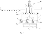
- the traditional spinning assembly is as shown in Fig. 5 , a metering device 1a communicates with polymer solution channels of a temperature control portion 3a through metal hoses 2a, spinneret portions 4a are arranged in the polymer solution channels of the temperature control portion 3a, a polymer solution for elastic fiber dry spinning is allocated into multiple beams of equal solution flows after being accurately metered by the metering device, the beams of the solution flows communicate with the spinneret portions arranged in the polymer solution channels of the temperature control portion through the metal hoses, and the beams of the polymer solution are sprayed into a spinning box through the spinneret portions.
- CN 103 911 679 discloses a spinning station and a polyurethane fiber production method based on a spinning station.
- the described spinning station comprises a conveying pipeline, a filtering pressure stabilizing device, a spinning component, a synchronous motor and a spinning box.
- WO 2009/1117536 refers to a spinning cell for a synthetic fiber such as spandex.
- the opening cell includes a top closure which reduces or eliminates solvent vapor transfer, where the solvent vapor process gas(es) may leave the cell and room air may be introduced into the spinning cell.
- JP 3 111 629 discloses a mechanism for maintenance of a spinneret portion for meet-spinning.
- the spinneret portion of the above-mentioned spinning assembly needs to be replaced, the metal hose and the spinneret portion need to be disconnected, the whole temperature control portion provided with the spinneret portion therein is disassembled, the portions of the temperature control portion including the spinneret portion are installed on the spinning assembly after being cleaned and checked out to be qualified, and then the production can be recovered.
- the disassembly and assembly works of the temperature control portion provided with the spinneret portion therein are tedious, the cleaning range is large, and the replacement time is long, thereby affecting the operation efficiency of the equipment and reducing the production efficiency.
- Embodiments of the present invention provide an elastic fiber dry spinning mechanism and a maintenance control method for a spinning assembly.
- an elastic fiber dry spinning mechanism including:
- the spinneret portion includes a rectangular plate, multiple rows of spinneret orifices are arranged on the rectangular plate, and at least one nozzle is arranged in one of the spinneret orifices.
- the spinning assembly further includes: at least one metering device and an interface conversion portion, and the metering device, the interface conversion portion, the temperature control portion and the spinneret portion are sequentially overlapped with each other.
- the spinning assembly further includes: at least one metering driving device used for driving the at least one metering device.
- the spinning assembly is rotatably connected with the moving bracket through at least one rotating shaft.
- the rotary movement control portion includes a first lifting driving mechanism used for driving the spinning assembly and the moving bracket to ascend and descend together.
- the first lifting driving mechanism drives the spinning assembly and the moving bracket to ascend and descend together from the upper side or the lower side of the spinning assembly.
- the moving bracket is provided with at least one moving bracket guiding portion extending along a lifting direction; and the rotary movement control portion includes a second lifting driving mechanism used for driving the spinning assembly to ascend and descend along the moving bracket guiding portion.
- the second lifting driving mechanism drives the spinning assembly to ascend and descend along the moving bracket guiding portion from the upper side or the lower side of the spinning assembly.
- the moving bracket guiding portion is provided with at least one limiting hole for limiting the spinning assembly after lifting the spinning assembly to a certain position through the cooperation with a limiting member.
- the rotary movement control portion includes: a first slide rail parallel to a first axis direction of the spinneret portion and used for limiting the spinning assembly to translate along the first slide rail after ascending and descending to a certain position.
- the rotary movement control portion further includes: a moving slide rail parallel to the first axis direction of the spinneret portion, the moving slide rail ascends or descends together with the spinning assembly or ascends or descends together with the spinning assembly and the moving bracket, and the moving slide rail limits the spinning assembly or the spinning assembly and the moving bracket to translate together with the first slide rail when ascending and descending to a position flush with the first slide rail.
- the rotary movement control portion includes: a second slide rail parallel to a second axis direction of the spinneret portion and used for limiting the spinning assembly to translate along the second slide rail after ascending and descending to a certain position.
- the rotary movement control portion includes a rotation driving mechanism having a self locking function and used for driving the spinning assembly to rotate around the translation direction and to realize self lock at multiple rotation angles.
- the rotation driving mechanism having the self locking function includes: an electric or manual reduction gear having a self locking function.
- the reduction gear having the self locking function includes a turbine vortex reducer.
- the orientation facilitating the maintenance of the spinneret portion is an upward orientation.
- the embodiments of the present invention further provide a maintenance control method for a spinning assembly based on the any elastic fiber dry spinning mechanism provided by the embodiments of the present invention, and the maintenance control method for the spinning assembly includes:
- the maintenance control method for the spinning assembly further includes: separating the spinneret portion from the temperature control portion, and detachably overlapping another spinneret portion with the temperature control portion.
- the maintenance control method for the spinning assembly further includes: driving the spinning assembly to rotate around the translation direction to change the orientation of the spinning assembly into an orientation facilitating the spinning of the other spinneret portion into the spinning box; driving the spinning assembly to translate to align the spinning assembly to the spinning box up and down; and driving the spinning assembly to descend to connect the spinning assembly with the spinning box.
- the temperature control portion and the spinneret portion contained in the elastic fiber dry spinning assembly are two portions which are detachably overlapped with each other, in a maintenance process of the spinning assembly, the entirety of the spinning assembly is driven to ascend and descend, translate and rotate around the translation direction through the rotary movement control portion to change the orientation of the spinning assembly into the orientation facilitating the maintenance of the spinneret portion, and then the spinneret portion and the temperature control portion only need to be separated and disassembled instead of disassembling the entirety of the spinning assembly, thereby reducing the range of assemblies requiring cleaning, replacement and other maintenance and reducing the workload of cleaning, replacement and other maintenance.
- another standby spinneret portion can be replaced, so that the online replacement and other maintenance of the spinneret portion are convenient, quick and efficient, and the influence on spinning production is little.
- the replaced spinneret portion can be performed with cleaning, assembly replacement and other offline maintenance, thereby avoiding the influence of the time necessary for the offline maintenance of the portion on the online spinning production, accordingly the spinning production interruption time necessary for the maintenance is shortened, and the production efficiency is improved.
- 1-spinning assembly 11-metering device; 12-interface conversion portion; 13-temperature control portion; 14-spinneret portion; 15-metering driving device; 16-rotating shaft; 2-moving bracket; 21-moving bracket guiding portion; 22- stop pin; 31-first slide rail; 32-moving slide rail; 33-second slide rail; 41-first lifting driving mechanism; 42-second lifting driving mechanism; 5-spinning shaft; 6-rotation driving mechanism; 1a-metering device; 2a-metal hose; 3a-temperature control portion; 4a-spinneret portion.
- the embodiment of the present invention provides an elastic fiber dry spinning mechanism, including: a spinning assembly, a rotary movement control portion, and a moving bracket; the spinning assembly includes a temperature control portion and a spinneret portion, which are detachably overlapped with each other; and the rotary movement control portion is used for driving the spinning assembly to ascend and descend, translate and rotate around a translation direction so as to change the orientation of the spinning assembly into an orientation facilitating the maintenance of the spinneret portion.
- the ascending and descending include up and down movements of ascending or descending relative to a certain reference position of the spinning assembly, and if a center axis of the spinning assembly is a vertical direction, the ascending and descending are up and down movements of a vertical plane relative to a certain reference position of the spinning assembly.
- the translation includes horizontal movement relative to left and right sides of a certain reference position of the spinning assembly, if the center axis of the spinning assembly is the vertical direction, the translation is the movement on a horizontal plane relative to a certain reference position of the spinning assembly, which can be left and right movement along the long axis direction of the spinneret portion, or can be front and back movement along the short axis direction of the spinneret portion, and so on.
- the orientation facilitating the maintenance of the spinneret portion can include, but not limited to, an upward orientation of the spinneret portion, and the maintenance can include, but not limited to, cleaning and/or replacement, etc.
- the spinning assembly In a dry spinning production process of elastic fibers such as spandex, the spinning assembly is usually disposed above a spinning box, and the spinneret portion is close to the spinning box.
- the spinning box can include, but not limited to, a spinning shaft, nozzles of the spinneret portion face to the interior of the spinning shaft, and a polymer solution for the elastic fibers is sprayed into the spinning shaft through the nozzles of the spinneret portion to perform such subsequent procedure processing of the elastic fibers, such as solvent evaporation, and so on.
- the polymer solution for elastic fiber dry spinning has certain chemical corrosion and viscosity and the like, the solution or impurities and the like will be accumulated in the nozzles of the spinneret portion to a certain extent after long time use, and the nozzles may be even blocked by serious accumulation. Therefore, the spinneret portion usually requires regular maintenance after a certain maintenance period.
- the spinneret portion is downward (i.e., the nozzles of the spinneret portion spin into the spinning shaft below) in a normal spinning working state, and when the spinneret portion is downward, it is inconvenient for cleaning, replacement and other maintenance.
- the rotary movement control portion can drive the spinning assembly to ascend to separate the spinning assembly from the spinning box below the spinning assembly, drive the spinning assembly to translate to stagger the spinning assembly to the spinning box, and drive the spinning assembly to rotate around the translation direction to change the orientation of the spinning assembly into the orientation facilitating the maintenance of the spinneret portion, for example, drive the spinning assembly to rotate around the translation direction to a position where the spinneret portion is upward.
- the spinneret portion can be separated from the temperature control portion, and another spinneret portion (e.g., a standby spinneret portion) is detachably overlapped with the temperature control portion.
- the rotary movement control portion can perform reverse movement or rotation according to the original movement track, for example, the spinning assembly is driven to rotate around the translation direction to change the orientation of the spinning assembly into an orientation facilitating the spinning of the other spinneret portion into the spinning box (e.g., the nozzle of the spinneret portion is downward); the spinning assembly is driven to translate to align the spinning assembly to the spinning box up and down; and the spinning assembly is driven to descend to connect the spinning assembly with the spinning box, and then the spinning assembly can recover to the original working state.
- the temperature control portion and the spinneret portion contained in the elastic fiber dry spinning assembly are two portions which are detachably overlapped with each other, in a maintenance process of the spinning assembly, the entirety of the spinning assembly is driven to ascend and descend, translate and rotate around the translation direction through the rotary movement control portion to change the orientation of the spinning assembly into the orientation facilitating the maintenance of the spinneret portion, and then the spinneret portion and the temperature control portion only need to be separated and disassembled instead of disassembling the entirety of the spinning assembly, thereby reducing the range of assemblies requiring cleaning, replacement and other maintenance and reducing the workload of cleaning, replacement and other maintenance.
- the other standby spinneret portion can be replaced, so that the online replacement time is short, and the influence on the spinning production is little.
- the replaced spinneret portion can be performed with cleaning, assembly replacement and other offline maintenance, thereby avoiding the influence of the time necessary for the offline maintenance of the portion on the online spinning production, accordingly the spinning production interruption time necessary for the maintenance is shortened, and the production efficiency is improved.
- the spinneret portion includes a rectangular plate, multiple rows of spinneret orifices are arranged on the rectangular plate, and at least one nozzle (Nozzle) is arranged in one of the spinneret orifices.
- each row of spinneret orifices can include a plurality of spinneret orifices arranged along the length direction of the rectangular plate at intervals, and one or more nozzles can be arranged in each spinneret orifice.
- the temperature control portion can include a box body for the flow of a temperature control medium, multiple rows of polymer solution passages isolated from each other are arranged on the box body, the polymer solution passages correspondingly communicate with the spinneret orifices, and the polymer solution for elastic fibers is transmitted to the corresponding spinneret orifices by the polymer solution passages and is ejected by the nozzles in the corresponding spinneret orifices.
- the spinneret portion in the solution can be matched with a spinning box including a rectangular spinning shaft, which is conducive to ejecting more fiber tows from a limited space so as to improve the yield.
- the spinneret portion can be an entirety to be conveniently disassembled and assembled on the whole; or the spinneret portion can include a plurality of spliced spinneret sub-portions, and the solution can better satisfy the block disassembly and assembly of the spinneret portions of spinning assemblies with high unit capacity.
- the production interruption time necessary for the maintenance by the traditional maintenance means in the background art is longer and longer, which seriously affects the continuous operation of the equipment and reduces the production efficiency, and the advantages of the technical solution provided by the embodiment of the present invention will be more obvious, such as small maintenance range, fast spinneret portion replacement, short interruption time, high efficiency, etc.
- the spinning assembly further includes: at least one metering device and an interface conversion portion, and the metering device, the interface conversion portion, the temperature control portion and the spinneret portion are sequentially overlapped with each other.
- the spinning assembly provided by the solution has a small volume and a compact structure, when the spinneret portion requires maintenance, the metering device, the interface conversion portion, the temperature control portion and the spinneret portion can be lifted, translated and rotated around the translation direction as an entirety, so that the orientation of the spinneret portion is the orientation facilitating the maintenance, and thus the convenience of maintenance and control is improved.
- the spinning assembly further includes: at least one metering driving device used for driving the metering device.
- the metering driving device, the metering device, the interface conversion portion, the temperature control portion and the spinneret portion can be lifted, translated and rotated around the translation direction as an entirety, so that the orientation of the spinneret portion is the orientation facilitating the maintenance, and thus the convenience of maintenance and control is improved.
- the elastic fiber dry spinning mechanism provided by the embodiment of the present invention further includes: a moving bracket used for providing support for the ascending and descending, translation and rotation of the spinning assembly.
- a moving bracket used for providing support for the ascending and descending, translation and rotation of the spinning assembly.
- the specific structure of the moving bracket can be flexibly designed according to actual demands, and this is not limited in the embodiment of the present invention.
- the spinning assembly is rotatably connected with the moving bracket through at least one rotating shaft.
- one or more rotating shafts can be arranged on the spinning assembly, and the spinning assembly is connected with the moving bracket through the rotating shaft, so that the entirety of the spinning assembly can rotate on the moving bracket under the drive of the rotary movement control portion, and the rotation stability is good.
- the rotary movement control portion includes a first lifting driving mechanism used for driving the spinning assembly and the moving bracket to ascend and descend together.
- the first lifting driving mechanism can include, but not limited to, a lifting cylinder, and under the action of a driving force provided by the first lifting driving mechanism, the spinning assembly and the moving bracket can ascend and descend together as an entirety so as to provide the stability of lifting movement.
- the manner of the first lifting driving mechanism to provide the driving force can be flexibly determined according to the demand of actual equipment layout, or a lifting mechanism supporting a certain driving mode can be flexibly selected to serve as the first lifting driving mechanism according to the demand of actual equipment layout.
- the first lifting driving mechanism can drive the spinning assembly and the moving bracket to ascend and descend together from the upper side of the spinning assembly.
- the spinning assembly and the moving bracket are driven to ascend and descend together as an entirety through the push-pull driving force of the first lifting driving mechanism, and the lifting driving mechanism can be flexibly deployed by fully using the upper side space of the spinning assembly.
- the first lifting driving mechanism can drive the spinning assembly and the moving bracket to ascend and descend together from the lower side of the spinning assembly.
- the spinning assembly and the moving bracket are driven to ascend and descend together as an entirety through the extension and contraction of a driving arm of the first lifting driving mechanism, and the lifting driving mechanism can be flexibly deployed by fully using the lower side space of the spinning assembly.
- the moving bracket is provided with at least one moving bracket guiding portion extending along a lifting direction; and the rotary movement control portion includes a second lifting driving mechanism used for driving the spinning assembly to ascend and descend along the moving bracket guiding portion.
- the second lifting driving mechanism can include, but not limited to, a lifting cylinder, and under the action of the driving force provided by the second lifting driving mechanism, the spinning assembly can ascend and descend along the moving bracket guiding portion so as to provide the stability of lifting movement.
- the manner of the second lifting driving mechanism to provide the driving force can be flexibly determined according to the demand of actual equipment layout, or a lifting mechanism supporting a certain driving mode can be flexibly selected to serve as the second lifting driving mechanism according to the demand of actual equipment layout.
- the second lifting driving mechanism can drive the spinning assembly to ascend and descend along the moving bracket guiding portion from the lower side of the spinning assembly.
- the spinning assembly is driven to ascend and descend along the moving bracket guiding portion through the extension and contraction of the driving arm of the second lifting driving mechanism, and the lifting driving mechanism can be flexibly deployed by fully using the lower side space of the spinning assembly.
- the second lifting driving mechanism can drive the spinning assembly to ascend and descend along the moving bracket guiding portion from the upper side of the spinning assembly.
- the spinning assembly is driven to ascend and descend along the moving bracket guiding portion through the push-pull driving force of the second lifting driving mechanism, and the lifting driving mechanism can be flexibly deployed by fully using the upper side space of the spinning assembly.
- the moving bracket guiding portion is provided with at least one limiting hole for limiting the spinning assembly after lifting the spinning assembly to a certain position through the cooperation with a limiting member.
- the shape and the dimension of the limiting hole can be designed according to actual demands, and the implementation is very flexible.
- the limiting member can include, but not limited to, a stop pin adapted to the limiting hole, and the like.
- the spinning assembly is limited when the same is lifted to a certain position by means of the limiting hole and the limiting member, and then the spinning assembly is translated, the solution is simple and easy to implement and is conducive to improving the operation stability.
- the rotary movement control portion includes: a first slide rail parallel to a first axis direction of the spinneret portion and used for limiting the spinning assembly to translate along the first slide rail after ascending and descending to a certain position.
- the spinneret portion can include a long axis extending along its length direction and a short axis extending along its width direction.
- the first axis can be the long axis, and the solution is conducive to moving the spinning assembly or the spinning assembly and the moving bracket into a space extending along the length direction of the spinneret portion and then performing rotation control on the spinning assembly in the space; or the first axis can be the short axis, and the solution is conducive to moving the spinning assembly or the spinning assembly and the moving bracket into a space extending along the width direction of the spinneret portion and then performing rotation control on the spinning assembly in the space.
- the spatial characteristics can be flexibly adapted to improve the operation convenience.
- the rotary movement control portion further includes: a moving slide rail parallel to the first axis direction of the spinneret portion, the moving slide rail ascends or descends together with the spinning assembly or ascends or descends together with the spinning assembly and the moving bracket, and the moving slide rail limits the spinning assembly or the spinning assembly and the moving bracket to translate together with the first slide rail when ascending and descending to a position flush with the first slide rail, and the solution is conducive to further improving the translation stability of the spinning assembly (or the spinning assembly and the moving bracket).
- the rotary movement control portion includes: a second slide rail parallel to a second axis direction of the spinneret portion and used for limiting the spinning assembly to translate along the second slide rail after ascending and descending to a certain position.
- the second axis can be a short axis, and the solution is conducive to moving the spinning assembly or the spinning assembly and the moving bracket into a space extending along the width direction of the spinneret portion and then performing rotation control on the spinning assembly in the space; or the second axis can be a long axis, and the solution is conducive to moving the spinning assembly or the spinning assembly and the moving bracket into a space extending along the length direction of the spinneret portion and then performing rotation control on the spinning assembly in the space.
- the spatial characteristics can be flexibly adapted to improve the operation convenience.
- the rotary movement control portion includes a rotation driving mechanism having a self locking function and used for driving the spinning assembly to rotate around the translation direction and to realize self lock at multiple rotation angles.
- a rotation driving mechanism having a self locking function of any angle on the rotation direction can be selected to improve the convenience of maintaining the spinning assembly from different angles.
- the rotation driving mechanism having the self locking function includes: an electric or manual reduction gear having a self locking function; the manual reduction gear can control the rotation angle through, but not limited to, a hand wheel and in other manners, the control is convenient, and the cost is low; the electric reduction gear can realize the electric control of the rotation angle in combination with, but not limited to, a braking device and in other manners, and the control is convenient and is relatively accurate.
- the reduction gear having the self locking function can include, but not limited to, a turbine vortex reducer, the movement and power between two alternating axes can be effectively transferred by the turbine vortex reducer to improve the efficiency, the self lock can be realized at any angle on the rotation direction to improve the rotation stability, even if the rotation angle is manually controlled, it is quite labor-saving, and the operation is convenient.
- an elastic fiber dry spinning mechanism provided by the embodiment of the present invention includes a spinning assembly 1, a moving bracket 2 and a rotary movement control portion.
- the spinning assembly 1 includes: at least one metering device 11, an interface conversion portion 12, a temperature control portion 13, a spinneret portion 14 and at least one metering driving device 15, the metering device 11, the interface conversion portion 12, the temperature control portion 13, the spinneret portion 14 and the metering driving device 15 are sequentially overlapped into an entirety with a relatively fixed position up and down, and at least the temperature control portion 13 and the spinneret portion 14 are detachable.
- a rotating shaft 16 is arranged at both ends of the spinning assembly 1, the spinning assembly 1 is connected with the moving bracket 2 through the rotating shaft 16, and thus the entirety of the spinning assembly 1 can rotate on the moving bracket 2.
- the rotary movement control portion includes a first lifting driving mechanism 41, a first slide rail 31, a moving slide rail 32 and a rotation driving mechanism 6, the first slide rail 31 and the moving slide rail 32 are relatively arranged on the long axis direction of the spinneret portion 14, and the moving slide rail 32 can ascend and ascend together with the spinning assembly 1 and the moving bracket 2.
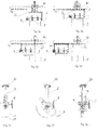
- the spinneret portion 14 When the spinning assembly 1 is in a normal spinning working state, the spinneret portion 14 is arranged at the top of the spinning box and communicates with a spinning shaft 5, and the spinneret portion 14 is downward, as shown in Fig. 2a . When the spinneret portion 14 needs to be replaced, the spinning production is interrupted.
- the first lifting driving mechanism 41 drives the entirety of the moving slide rail 32, the moving bracket 2 and the spinning assembly 1 to ascend to a position as high as the first slide rail 31 along the vertical direction, as shown in Fig. 2b .
- a driving force (the driving force can be manually applied, for example, thrust; or can be applied by an external power mechanism and the like) of translating along the long axis direction of the spinneret portion is applied to the entirety of the moving bracket 2 and the spinning assembly 1, so that the entirety of the moving bracket 2 and the spinning assembly 1 translates onto the first slide rail 31 along the moving slide rail 32, as shown in Fig. 2c .
- the spinning assembly 1 completely staggers to the spinning shaft after completely moving onto the first slide rail 31 as shown in Fig. 2d .
- the rotation driving mechanism 6 can include, but not limited to, a manual turbine vortex reducer, and the rotation driving mechanism 6 outputs the power to the rotating shaft 16, so that the entirety of the spinning assembly rotates on the moving bracket 2, as shown in Fig. 2e and Fig. 2f .
- the orientation of the spinneret portion of the spinning assembly is an orientation facilitating the maintenance, for example, the spinneret portion of the spinning assembly is turned over to be upward after positive rotation for 180 degrees, as shown in Fig. 2g . Therefore, the spinneret portion 14 can be disassembled, and another spinneret portion 14 is replaced.
- the rotation driving mechanism 6 outputs the power to the rotating shaft 16, so that the entirety of the spinning assembly reversely rotates on the moving bracket 2, the orientation of the spinneret portion of the spinning assembly rotating to a certain angle is an orientation facilitating the spinning toward the spinning shaft 5, for example, the spinneret portion of the spinning assembly is turned over to be downward after reverse rotation for 180 degrees.
- a driving force of translating along the long axis direction of the spinneret portion is applied to the entirety of the moving bracket 2 and the spinning assembly 1, so that the entirety of the moving bracket 2 and the spinning assembly 1 translates onto the moving slide rail 32 along the first slide rail 31, and the spinning assembly 1 is aligned to the spinning shaft up and down after completely moving onto the moving slide rail 32.
- the first lifting driving mechanism 41 drives the entirety of the moving slide rail 32, the moving bracket 2 and the spinning assembly 1 to descend along the vertical direction until the spinneret portion 14 is connected with the spinning shaft 5.
- the replacement maintenance of the spinneret portion 14 is accomplished, the spinning production of the elastic fibers can be recovered, and cleaning, assembly replacement and other subsequent offline maintenance can be performed on the disassembled spinneret portion 14 subsequently. Therefore, in the solution, spinneret portion and the temperature control portion only need to be separated and disassembled instead of disassembling the entirety of the spinning assembly, thereby reducing the range of assemblies requiring cleaning, replacement and other maintenance and reducing the workload of cleaning, replacement and other maintenance. In addition, the online maintenance time is short, the influence on spinning production is little, and the production efficiency is improved.
- an elastic fiber dry spinning mechanism provided by the embodiment of the present invention includes a spinning assembly 1, a moving bracket 2 and a rotary movement control portion.
- the spinning assembly 1 includes: at least one metering device 11, an interface conversion portion 12, a temperature control portion 13, a spinneret portion 14 and at least one metering driving device 15, the metering device 11, the interface conversion portion 12, the temperature control portion 13, the spinneret portion 14 and the metering driving device 15 are sequentially overlapped into an entirety with a relatively fixed position up and down, and at least the temperature control portion 13 and the spinneret portion 14 are detachable.
- a rotating shaft 16 is arranged at both ends of the spinning assembly 1, the spinning assembly 1 is connected with the moving bracket 2 through the rotating shaft 16, and thus the entirety of the spinning assembly 1 can rotate on the moving bracket 2.
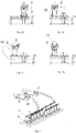
- a moving bracket guiding portion 21 is respectively arranged on both sides of the moving bracket 2, and the spinning assembly 1 can ascend and descend along the moving bracket guiding portion 21; a plurality of limiting holes can be arranged on the moving bracket guiding portion 21 at intervals, for example, a stopper pin 22 and other limiting member is inserted into the limiting hole at a corresponding height to limit the lifting direction of the spinning assembly.
- the rotary movement control portion includes a second lifting driving mechanism 42, a second slide rail 33 and a rotation driving mechanism 6, and the second slide rail 33 is arranged along the short axis direction of the spinneret portion 14.
- the spinneret portion 14 When the spinning assembly 1 is in a normal spinning working state, the spinneret portion 14 is arranged at the top of the spinning box and communicates with a spinning shaft 5, and the spinneret portion 14 is downward, as shown in Fig. 4a . When the spinneret portion 14 needs to be replaced, the spinning production is interrupted.
- the second lifting driving mechanism 42 drives the spinning assembly 1 to ascend to a position along the vertical direction, as shown in Fig. 4b , and the stop pin 22 is inserted into the limiting hole formed in the corresponding height of the moving bracket guiding portion 21 to limit the spinning assembly 1 as shown in Fig. 4c .
- a driving force (the driving force can be manually applied, for example, thrust; or can be applied by an external power mechanism and the like) of translating along the short axis direction of the spinneret portion is applied to the entirety of the moving bracket 2 and the spinning assembly 1, so that the entirety of the moving bracket 2 and the spinning assembly 1 translates along the second slide rail 31 until the spinning assembly 1 staggers to the spinning shaft, as shown in Fig. 4d to Fig. 4e .
- the rotation driving mechanism 6, such as a manual turbine vortex reducer, outputs the power to the rotating shaft 16, so that the entirety of the spinning assembly rotates on the moving bracket 2, after rotating to a certain angle, the orientation of the spinneret portion of the spinning assembly is an orientation facilitating the maintenance as shown in Fig. 4f to Fig. 4g , for example, the spinneret portion of the spinning assembly is obliquely upward relative to the horizontal direction after positive rotation for certain degrees, for example, the spinneret portion of the spinning assembly is upward after positive rotation for 180 degrees. Therefore, the spinneret portion 14 can be disassembled, and another spinneret portion 14 is replaced.
- the rotation driving mechanism 6 outputs the power to the rotating shaft 16, so that the entirety of the spinning assembly reversely rotates on the moving bracket 2, the orientation of the spinneret portion of the spinning assembly rotating to a certain angle is an orientation facilitating the spinning toward the spinning shaft 5, for example, the spinneret portion of the spinning assembly is turned over to be downward after reverse rotation for certain angles, for example, the spinneret portion of the spinning assembly is turned over to be downward after reverse rotation for 180 degrees.
- a driving force of translating along the short axis direction of the spinneret portion is applied to the entirety of the moving bracket 2 and the spinning assembly 1, so that the entirety of the moving bracket 2 and the spinning assembly 1 translates onto the a position where the spinning assembly 1 is aligned to the spinning shaft up and down.
- the stop pin 22 inserted into the limiting hole of the moving bracket guiding portion 21 is taken out, the second lifting driving mechanism 42 drives the entirety of the moving bracket 2 and the spinning assembly 1 to descend along the vertical direction until the spinneret portion 14 is connected with the spinning shaft 5.
- the replacement maintenance of the spinneret portion 14 is accomplished, the spinning production of the elastic fibers can be recovered, and cleaning, assembly replacement and other subsequent offline maintenance can be performed on the disassembled spinneret portion 14 subsequently. Therefore, in the solution, the spinneret portion and the temperature control portion only need to be separated and disassembled instead of disassembling the entirety of the spinning assembly, thereby reducing the range of assemblies requiring cleaning, replacement and other maintenance and reducing the workload of cleaning, replacement and other maintenance. In addition, the online maintenance time is short, the influence on spinning production is little, and the production efficiency is improved.
Landscapes
- Engineering & Computer Science (AREA)
- Mechanical Engineering (AREA)
- Textile Engineering (AREA)
- Spinning Methods And Devices For Manufacturing Artificial Fibers (AREA)
- Spinning Or Twisting Of Yarns (AREA)
Claims (9)
- Trockenspinnmechanismus für elastische Fasern, umfassend:ein Spinnaggregat (1), das einen Temperatursteuerungsteil (13) und einen Spinndüsenteil (14) umfasst, die einander lösbar überlappen;einen Drehbewegungssteuerungsteil, der verwendet wird, um das Spinnaggregat (1) so anzutreiben, dass es steigt und sinkt, sich verschiebt und um eine Translationsrichtung rotiert, um die Orientierung des Spinnaggregats (1) zu einer Orientierung zu verändern, die die Wartung des Spinndüsenteils erleichtert; undeine bewegliche Klammer (2), die verwendet wird, um einen Halt für das Steigen und Sinken, die Verschiebung und Drehung des Spinnaggregats (1) zu geben.
- Trockenspinnmechanismus für elastische Fasern gemäß Anspruch 1, wobei das Spinnaggregat (1) weiterhin wenigstens eine Dosiervorrichtung (11) und einen Schnittstellenumwandlungsteil (12) umfasst und die Dosiervorrichtung (11), der Schnittstellenumwandlungsteil (12), der Temperatursteuerungsteil (13) und der Spinndüsenteil (14) einander nacheinander überlappen.
- Trockenspinnmechanismus für elastische Fasern gemäß Anspruch 1, wobei das Spinnaggregat (1) über wenigstens eine rotierende Welle (16) drehbar mit der beweglichen Klammer (2) verbunden ist.
- Trockenspinnmechanismus für elastische Fasern gemäß Anspruch 1, wobei der Drehbewegungssteuerungsteil umfasst: eine erste Gleitschiene (31) parallel zu einer ersten Achsenrichtung des Spinndüsenteils (14), die verwendet wird, um das Spinnaggregat (1) so einzuschränken, dass es sich entlang der ersten Gleitschiene (31) verschiebt, nachdem es auf eine bestimmte Position gestiegen und gesunken ist.
- Trockenspinnmechanismus für elastische Fasern gemäß Anspruch 4, wobei
der Drehbewegungssteuerungsteil weiterhin umfasst: eine bewegliche Gleitschiene (32) parallel zu der ersten Achsenrichtung des Spinndüsenteils (14), wobei die bewegliche Gleitschiene (32) zusammen mit dem Spinnaggregat (1) steigt oder sinkt oder zusammen mit dem Spinnaggregat (1) und der beweglichen Klammer (2) steigt oder sinkt und die bewegliche Gleitschiene (32) das Spinnaggregat (1) oder das Spinnaggregat (1) und die bewegliche Klammer (2) so einschränkt, dass sie sich zusammen mit der ersten Gleitschiene (31) verschieben, wenn sie auf eine Position gestiegen und gesunken sind, die mit der ersten Gleitschiene (31) bündig abschließt. - Trockenspinnmechanismus für elastische Fasern gemäß Anspruch 4, wobei der Drehbewegungssteuerungsteil umfasst: eine zweite Gleitschiene (33) parallel zu einer zweiten Achsenrichtung des Spinndüsenteils (14), die verwendet wird, um das Spinnaggregat (1) so einzuschränken, dass es sich entlang der zweiten Gleitschiene (33) verschiebt, nachdem es auf eine bestimmte Position gestiegen und gesunken ist.
- Wartungskontrollverfahren für ein Spinnaggregat, das auf dem Trockenspinnmechanismus für elastische Fasern gemäß einem der Ansprüche 1-6 beruht, umfassend:Antreiben des Spinnaggregats, so dass es steigt und dadurch das Spinnaggregat aus einem Spinnkasten unterhalb des Spinnaggregats trennt;Antreiben des Spinnaggregats, so dass es sich verschiebt, um das Spinnaggregat gegenüber dem Spinnkasten versetzt anzuordnen; undAntreiben des Spinnaggregats, so dass es sich um eine Translationsrichtung dreht, um die Orientierung des Spinnaggregats zu einer Orientierung zu verändern, die die Wartung des Spinndüsenteils erleichtert.
- Verfahren gemäß Anspruch 7, wobei das Verfahren, nachdem die Orientierung des Spinnaggregats zu einer Orientierung, die die Wartung des Spinndüsenteils erleichtert, verändert wurde, weiterhin umfasst: Abtrennen des Spinndüsenteils von dem Temperatursteuerungsteil und Sich-Iösbar-Überlappenlassen eines anderen Spinndüsenteils mit dem Temperatursteuerungsteil.
- Verfahren gemäß Anspruch 7 oder 8, wobei das Verfahren, nachdem der andere Spinndüsenteil mit dem Temperatursteuerungsteil lösbar überlappt wurde, weiterhin umfasst:Antreiben des Spinnaggregats, so dass es sich um die Translationsrichtung dreht, um die Orientierung des Spinnaggregats zu einer Orientierung zu verändern, die das Spinnen des anderen Spinndüsenteils in den Spinnkasten erleichtert;Antreiben des Spinnaggregats, so dass es sich verschiebt, um das Spinnaggregat an dem Spinnkasten hoch oder herunter auszurichten; undAntreiben des Spinnaggregats, so dass es sinkt, um das Spinnaggregat mit dem Spinnkasten zu verbinden.
Applications Claiming Priority (1)
| Application Number | Priority Date | Filing Date | Title |
|---|---|---|---|
| PCT/CN2015/071435 WO2016115730A1 (zh) | 2015-01-23 | 2015-01-23 | 弹性纤维干法纺丝机构及纺丝部件维护控制方法 |
Publications (3)
| Publication Number | Publication Date |
|---|---|
| EP3249083A1 EP3249083A1 (de) | 2017-11-29 |
| EP3249083A4 EP3249083A4 (de) | 2018-01-10 |
| EP3249083B1 true EP3249083B1 (de) | 2019-01-02 |
Family
ID=56416310
Family Applications (1)
| Application Number | Title | Priority Date | Filing Date |
|---|---|---|---|
| EP15878407.4A Active EP3249083B1 (de) | 2015-01-23 | 2015-01-23 | Dehnfasertrockenspinnmechanismus und wartungssteuerungsverfahren für spinnanordnung |
Country Status (6)
| Country | Link |
|---|---|
| US (1) | US20180016708A1 (de) |
| EP (1) | EP3249083B1 (de) |
| JP (1) | JP6500111B2 (de) |
| KR (1) | KR20170098260A (de) |
| BR (1) | BR112017015306B1 (de) |
| WO (1) | WO2016115730A1 (de) |
Families Citing this family (7)
| Publication number | Priority date | Publication date | Assignee | Title |
|---|---|---|---|---|
| US10312944B2 (en) * | 2017-03-17 | 2019-06-04 | Micron Technology, Inc. | Error correction code (ECC) operations in memory for providing redundant error correction |
| CN109355714B (zh) * | 2018-12-28 | 2023-07-07 | 苏州软石智能装备有限公司 | 纺丝机的喷丝板自动清洁装置 |
| CN110274247B (zh) * | 2019-06-19 | 2020-11-06 | 湖南东映碳材料科技有限公司 | 一种喷丝板高温焚烧清洗炉 |
| CN111778573B (zh) * | 2020-07-30 | 2021-07-27 | 安徽信德化纤有限公司 | 一种用于纺丝过程的助剂喷淋设备及其使用方法 |
| CN112725907B (zh) * | 2020-12-23 | 2022-06-14 | 江苏关怀医疗科技有限公司 | 纺丝线机头 |
| CN112923699A (zh) * | 2021-02-05 | 2021-06-08 | 陈丽荧 | 一种用于化纤纺丝用喷丝头快速干燥装置 |
| CN113400253A (zh) * | 2021-05-10 | 2021-09-17 | 苏州朗科智能制造有限公司 | 一种用于更换纺丝组件的装置 |
Family Cites Families (15)
| Publication number | Priority date | Publication date | Assignee | Title |
|---|---|---|---|---|
| FR759986A (fr) * | 1933-08-08 | 1934-02-14 | Procédé et installation pour la fabrication de filés artificiels | |
| US3458616A (en) * | 1967-05-11 | 1969-07-29 | Du Pont | Dry spinning process and apparatus |
| JPS609907A (ja) * | 1983-06-27 | 1985-01-19 | Toray Ind Inc | 紡糸パツク交換装置 |
| JP3111629B2 (ja) * | 1992-04-14 | 2000-11-27 | 東レ株式会社 | 紡糸パック収納装置 |
| JP3174154B2 (ja) * | 1992-06-26 | 2001-06-11 | 三共有機合成株式会社 | カチオン電着塗料用硬化触媒 |
| US6210141B1 (en) * | 1998-02-10 | 2001-04-03 | Nordson Corporation | Modular die with quick change die tip or nozzle |
| BRPI0906189B1 (pt) * | 2008-03-19 | 2019-01-29 | Invista Tech Sarl | dispositivos e método para reduzir ou eliminar emissões de vapor do solvente e/ou a introdução de ar em uma célula de fiação seca. |
| CN101831719B (zh) * | 2010-05-21 | 2012-05-09 | 江苏神泰科技发展有限公司 | 高性能纤维同步辐射原位检测试验机 |
| CN105463592B (zh) * | 2010-09-09 | 2017-12-22 | 松下知识产权经营株式会社 | 纳米纤维制造装置以及纳米纤维制造方法 |
| CN103911679B (zh) * | 2011-09-19 | 2016-06-08 | 郑州中远氨纶工程技术有限公司 | 纺丝工位及基于该纺丝工位的聚氨酯纤维生产方法 |
| CN102358960B (zh) * | 2011-09-19 | 2014-04-16 | 郑州中远氨纶工程技术有限公司 | 纺丝组件和纺丝部件 |
| CN203728970U (zh) * | 2013-11-07 | 2014-07-23 | 安吉峰源纺织有限公司 | 一种喷丝组件升降装置 |
| CN203846155U (zh) * | 2014-05-15 | 2014-09-24 | 浙江德润化纤有限公司 | 一种用于锦纶纺丝生产的可调单体抽吸罩 |
| CN204509518U (zh) * | 2015-01-23 | 2015-07-29 | 郑州中远氨纶工程技术有限公司 | 弹性纤维干法纺丝机构 |
| CN104831366B (zh) * | 2015-01-23 | 2017-04-05 | 郑州中远氨纶工程技术有限公司 | 弹性纤维干法纺丝机构及纺丝部件维护控制方法 |
-
2015
- 2015-01-23 JP JP2017537992A patent/JP6500111B2/ja active Active
- 2015-01-23 WO PCT/CN2015/071435 patent/WO2016115730A1/zh not_active Ceased
- 2015-01-23 US US15/544,247 patent/US20180016708A1/en not_active Abandoned
- 2015-01-23 KR KR1020177019983A patent/KR20170098260A/ko not_active Ceased
- 2015-01-23 BR BR112017015306-8A patent/BR112017015306B1/pt active IP Right Grant
- 2015-01-23 EP EP15878407.4A patent/EP3249083B1/de active Active
Non-Patent Citations (1)
| Title |
|---|
| None * |
Also Published As
| Publication number | Publication date |
|---|---|
| EP3249083A4 (de) | 2018-01-10 |
| US20180016708A1 (en) | 2018-01-18 |
| WO2016115730A1 (zh) | 2016-07-28 |
| JP6500111B2 (ja) | 2019-04-10 |
| EP3249083A1 (de) | 2017-11-29 |
| KR20170098260A (ko) | 2017-08-29 |
| JP2018502229A (ja) | 2018-01-25 |
| BR112017015306B1 (pt) | 2021-11-09 |
| BR112017015306A2 (pt) | 2018-01-09 |
Similar Documents
| Publication | Publication Date | Title |
|---|---|---|
| EP3249083B1 (de) | Dehnfasertrockenspinnmechanismus und wartungssteuerungsverfahren für spinnanordnung | |
| CN101314248A (zh) | 胶类手套在线自动脱模机 | |
| CN106000731A (zh) | 一种喷涂装置 | |
| CN204509518U (zh) | 弹性纤维干法纺丝机构 | |
| EP3623062A1 (de) | Reinigungsvorrichtung und reinigungseinrichtung | |
| CN104289846A (zh) | H型钢焊接组立设备 | |
| CN203013578U (zh) | Gw5隔离开关触头拆装工具 | |
| CN104831366A (zh) | 弹性纤维干法纺丝机构及纺丝部件维护控制方法 | |
| CN109173464B (zh) | 一种基于多个子笼架的除尘滤袋 | |
| CN108607739A (zh) | 用于静电喷涂的喷枪驱动装置 | |
| CN206017060U (zh) | 塔筒及塔筒系统 | |
| CN212834789U (zh) | 一种全自动旋转式纸浆模塑热压定型一体化生产设备 | |
| CN105173917A (zh) | 一种多功能印花钢板卷装架 | |
| CN211114501U (zh) | 一种大尺寸零件用电火花加工平台防护栏 | |
| CN112748184B (zh) | 一种用于配电网的超声波隐患检测装置 | |
| CN216769002U (zh) | 一种导轨式农业监控设备安装机构 | |
| CN207763525U (zh) | 一种便于电机拆卸的冷却塔 | |
| CN223288147U (zh) | 一种中药材须根破碎去除装置 | |
| CN208288639U (zh) | 玻璃双面清刷机和玻璃双面清刷设备 | |
| CN221360518U (zh) | 一种广角式喷淋设备 | |
| CN112665409A (zh) | 冷却塔和制冷系统 | |
| CN203734464U (zh) | 电机轴密封圈压接装置 | |
| CN220910251U (zh) | 一种剖分轴承保持架的连接装置 | |
| CN210411294U (zh) | 一种摩托车发动机右大盖喷漆装置 | |
| CN104624671B (zh) | 一种改进型轧机导卫设备的自动修正方法 |
Legal Events
| Date | Code | Title | Description |
|---|---|---|---|
| STAA | Information on the status of an ep patent application or granted ep patent |
Free format text: STATUS: THE INTERNATIONAL PUBLICATION HAS BEEN MADE |
|
| PUAI | Public reference made under article 153(3) epc to a published international application that has entered the european phase |
Free format text: ORIGINAL CODE: 0009012 |
|
| STAA | Information on the status of an ep patent application or granted ep patent |
Free format text: STATUS: REQUEST FOR EXAMINATION WAS MADE |
|
| 17P | Request for examination filed |
Effective date: 20170816 |
|
| AK | Designated contracting states |
Kind code of ref document: A1 Designated state(s): AL AT BE BG CH CY CZ DE DK EE ES FI FR GB GR HR HU IE IS IT LI LT LU LV MC MK MT NL NO PL PT RO RS SE SI SK SM TR |
|
| AX | Request for extension of the european patent |
Extension state: BA ME |
|
| A4 | Supplementary search report drawn up and despatched |
Effective date: 20171211 |
|
| RIC1 | Information provided on ipc code assigned before grant |
Ipc: D01D 4/08 20060101ALI20171204BHEP Ipc: D01D 4/04 20060101ALN20171204BHEP Ipc: D01D 11/00 20060101ALI20171204BHEP Ipc: D01D 5/04 20060101ALN20171204BHEP Ipc: D01D 4/00 20060101AFI20171204BHEP |
|
| DAX | Request for extension of the european patent (deleted) | ||
| GRAP | Despatch of communication of intention to grant a patent |
Free format text: ORIGINAL CODE: EPIDOSNIGR1 |
|
| STAA | Information on the status of an ep patent application or granted ep patent |
Free format text: STATUS: GRANT OF PATENT IS INTENDED |
|
| RIC1 | Information provided on ipc code assigned before grant |
Ipc: D01D 4/08 20060101ALI20180731BHEP Ipc: D01D 5/04 20060101ALN20180731BHEP Ipc: D01D 11/00 20060101ALI20180731BHEP Ipc: D01D 4/00 20060101AFI20180731BHEP Ipc: D01D 4/04 20060101ALN20180731BHEP |
|
| INTG | Intention to grant announced |
Effective date: 20180817 |
|
| GRAS | Grant fee paid |
Free format text: ORIGINAL CODE: EPIDOSNIGR3 |
|
| GRAA | (expected) grant |
Free format text: ORIGINAL CODE: 0009210 |
|
| STAA | Information on the status of an ep patent application or granted ep patent |
Free format text: STATUS: THE PATENT HAS BEEN GRANTED |
|
| AK | Designated contracting states |
Kind code of ref document: B1 Designated state(s): AL AT BE BG CH CY CZ DE DK EE ES FI FR GB GR HR HU IE IS IT LI LT LU LV MC MK MT NL NO PL PT RO RS SE SI SK SM TR |
|
| REG | Reference to a national code |
Ref country code: GB Ref legal event code: FG4D |
|
| REG | Reference to a national code |
Ref country code: CH Ref legal event code: EP Ref country code: AT Ref legal event code: REF Ref document number: 1084498 Country of ref document: AT Kind code of ref document: T Effective date: 20190115 |
|
| REG | Reference to a national code |
Ref country code: IE Ref legal event code: FG4D |
|
| REG | Reference to a national code |
Ref country code: DE Ref legal event code: R096 Ref document number: 602015023019 Country of ref document: DE |
|
| REG | Reference to a national code |
Ref country code: NL Ref legal event code: MP Effective date: 20190102 |
|
| REG | Reference to a national code |
Ref country code: LT Ref legal event code: MG4D |
|
| REG | Reference to a national code |
Ref country code: AT Ref legal event code: MK05 Ref document number: 1084498 Country of ref document: AT Kind code of ref document: T Effective date: 20190102 |
|
| PG25 | Lapsed in a contracting state [announced via postgrant information from national office to epo] |
Ref country code: NL Free format text: LAPSE BECAUSE OF FAILURE TO SUBMIT A TRANSLATION OF THE DESCRIPTION OR TO PAY THE FEE WITHIN THE PRESCRIBED TIME-LIMIT Effective date: 20190102 |
|
| PG25 | Lapsed in a contracting state [announced via postgrant information from national office to epo] |
Ref country code: SE Free format text: LAPSE BECAUSE OF FAILURE TO SUBMIT A TRANSLATION OF THE DESCRIPTION OR TO PAY THE FEE WITHIN THE PRESCRIBED TIME-LIMIT Effective date: 20190102 Ref country code: PL Free format text: LAPSE BECAUSE OF FAILURE TO SUBMIT A TRANSLATION OF THE DESCRIPTION OR TO PAY THE FEE WITHIN THE PRESCRIBED TIME-LIMIT Effective date: 20190102 Ref country code: PT Free format text: LAPSE BECAUSE OF FAILURE TO SUBMIT A TRANSLATION OF THE DESCRIPTION OR TO PAY THE FEE WITHIN THE PRESCRIBED TIME-LIMIT Effective date: 20190502 Ref country code: NO Free format text: LAPSE BECAUSE OF FAILURE TO SUBMIT A TRANSLATION OF THE DESCRIPTION OR TO PAY THE FEE WITHIN THE PRESCRIBED TIME-LIMIT Effective date: 20190402 Ref country code: FI Free format text: LAPSE BECAUSE OF FAILURE TO SUBMIT A TRANSLATION OF THE DESCRIPTION OR TO PAY THE FEE WITHIN THE PRESCRIBED TIME-LIMIT Effective date: 20190102 Ref country code: ES Free format text: LAPSE BECAUSE OF FAILURE TO SUBMIT A TRANSLATION OF THE DESCRIPTION OR TO PAY THE FEE WITHIN THE PRESCRIBED TIME-LIMIT Effective date: 20190102 Ref country code: LT Free format text: LAPSE BECAUSE OF FAILURE TO SUBMIT A TRANSLATION OF THE DESCRIPTION OR TO PAY THE FEE WITHIN THE PRESCRIBED TIME-LIMIT Effective date: 20190102 |
|
| PG25 | Lapsed in a contracting state [announced via postgrant information from national office to epo] |
Ref country code: IS Free format text: LAPSE BECAUSE OF FAILURE TO SUBMIT A TRANSLATION OF THE DESCRIPTION OR TO PAY THE FEE WITHIN THE PRESCRIBED TIME-LIMIT Effective date: 20190502 Ref country code: HR Free format text: LAPSE BECAUSE OF FAILURE TO SUBMIT A TRANSLATION OF THE DESCRIPTION OR TO PAY THE FEE WITHIN THE PRESCRIBED TIME-LIMIT Effective date: 20190102 Ref country code: RS Free format text: LAPSE BECAUSE OF FAILURE TO SUBMIT A TRANSLATION OF THE DESCRIPTION OR TO PAY THE FEE WITHIN THE PRESCRIBED TIME-LIMIT Effective date: 20190102 Ref country code: LV Free format text: LAPSE BECAUSE OF FAILURE TO SUBMIT A TRANSLATION OF THE DESCRIPTION OR TO PAY THE FEE WITHIN THE PRESCRIBED TIME-LIMIT Effective date: 20190102 Ref country code: GR Free format text: LAPSE BECAUSE OF FAILURE TO SUBMIT A TRANSLATION OF THE DESCRIPTION OR TO PAY THE FEE WITHIN THE PRESCRIBED TIME-LIMIT Effective date: 20190403 Ref country code: BG Free format text: LAPSE BECAUSE OF FAILURE TO SUBMIT A TRANSLATION OF THE DESCRIPTION OR TO PAY THE FEE WITHIN THE PRESCRIBED TIME-LIMIT Effective date: 20190402 |
|
| REG | Reference to a national code |
Ref country code: CH Ref legal event code: PL |
|
| PG25 | Lapsed in a contracting state [announced via postgrant information from national office to epo] |
Ref country code: LU Free format text: LAPSE BECAUSE OF NON-PAYMENT OF DUE FEES Effective date: 20190123 |
|
| REG | Reference to a national code |
Ref country code: DE Ref legal event code: R097 Ref document number: 602015023019 Country of ref document: DE |
|
| REG | Reference to a national code |
Ref country code: BE Ref legal event code: MM Effective date: 20190131 |
|
| REG | Reference to a national code |
Ref country code: IE Ref legal event code: MM4A |
|
| PG25 | Lapsed in a contracting state [announced via postgrant information from national office to epo] |
Ref country code: AL Free format text: LAPSE BECAUSE OF FAILURE TO SUBMIT A TRANSLATION OF THE DESCRIPTION OR TO PAY THE FEE WITHIN THE PRESCRIBED TIME-LIMIT Effective date: 20190102 Ref country code: CZ Free format text: LAPSE BECAUSE OF FAILURE TO SUBMIT A TRANSLATION OF THE DESCRIPTION OR TO PAY THE FEE WITHIN THE PRESCRIBED TIME-LIMIT Effective date: 20190102 Ref country code: IT Free format text: LAPSE BECAUSE OF FAILURE TO SUBMIT A TRANSLATION OF THE DESCRIPTION OR TO PAY THE FEE WITHIN THE PRESCRIBED TIME-LIMIT Effective date: 20190102 Ref country code: RO Free format text: LAPSE BECAUSE OF FAILURE TO SUBMIT A TRANSLATION OF THE DESCRIPTION OR TO PAY THE FEE WITHIN THE PRESCRIBED TIME-LIMIT Effective date: 20190102 Ref country code: DK Free format text: LAPSE BECAUSE OF FAILURE TO SUBMIT A TRANSLATION OF THE DESCRIPTION OR TO PAY THE FEE WITHIN THE PRESCRIBED TIME-LIMIT Effective date: 20190102 Ref country code: AT Free format text: LAPSE BECAUSE OF FAILURE TO SUBMIT A TRANSLATION OF THE DESCRIPTION OR TO PAY THE FEE WITHIN THE PRESCRIBED TIME-LIMIT Effective date: 20190102 Ref country code: EE Free format text: LAPSE BECAUSE OF FAILURE TO SUBMIT A TRANSLATION OF THE DESCRIPTION OR TO PAY THE FEE WITHIN THE PRESCRIBED TIME-LIMIT Effective date: 20190102 Ref country code: SK Free format text: LAPSE BECAUSE OF FAILURE TO SUBMIT A TRANSLATION OF THE DESCRIPTION OR TO PAY THE FEE WITHIN THE PRESCRIBED TIME-LIMIT Effective date: 20190102 Ref country code: MC Free format text: LAPSE BECAUSE OF FAILURE TO SUBMIT A TRANSLATION OF THE DESCRIPTION OR TO PAY THE FEE WITHIN THE PRESCRIBED TIME-LIMIT Effective date: 20190102 |
|
| PLBE | No opposition filed within time limit |
Free format text: ORIGINAL CODE: 0009261 |
|
| STAA | Information on the status of an ep patent application or granted ep patent |
Free format text: STATUS: NO OPPOSITION FILED WITHIN TIME LIMIT |
|
| PG25 | Lapsed in a contracting state [announced via postgrant information from national office to epo] |
Ref country code: BE Free format text: LAPSE BECAUSE OF NON-PAYMENT OF DUE FEES Effective date: 20190131 Ref country code: SM Free format text: LAPSE BECAUSE OF FAILURE TO SUBMIT A TRANSLATION OF THE DESCRIPTION OR TO PAY THE FEE WITHIN THE PRESCRIBED TIME-LIMIT Effective date: 20190102 |
|
| 26N | No opposition filed |
Effective date: 20191003 |
|
| PG25 | Lapsed in a contracting state [announced via postgrant information from national office to epo] |
Ref country code: LI Free format text: LAPSE BECAUSE OF NON-PAYMENT OF DUE FEES Effective date: 20190131 Ref country code: CH Free format text: LAPSE BECAUSE OF NON-PAYMENT OF DUE FEES Effective date: 20190131 |
|
| PG25 | Lapsed in a contracting state [announced via postgrant information from national office to epo] |
Ref country code: IE Free format text: LAPSE BECAUSE OF NON-PAYMENT OF DUE FEES Effective date: 20190123 |
|
| PG25 | Lapsed in a contracting state [announced via postgrant information from national office to epo] |
Ref country code: SI Free format text: LAPSE BECAUSE OF FAILURE TO SUBMIT A TRANSLATION OF THE DESCRIPTION OR TO PAY THE FEE WITHIN THE PRESCRIBED TIME-LIMIT Effective date: 20190102 Ref country code: FR Free format text: LAPSE BECAUSE OF NON-PAYMENT OF DUE FEES Effective date: 20190302 |
|
| PG25 | Lapsed in a contracting state [announced via postgrant information from national office to epo] |
Ref country code: MT Free format text: LAPSE BECAUSE OF NON-PAYMENT OF DUE FEES Effective date: 20190123 |
|
| PG25 | Lapsed in a contracting state [announced via postgrant information from national office to epo] |
Ref country code: CY Free format text: LAPSE BECAUSE OF FAILURE TO SUBMIT A TRANSLATION OF THE DESCRIPTION OR TO PAY THE FEE WITHIN THE PRESCRIBED TIME-LIMIT Effective date: 20190102 |
|
| PG25 | Lapsed in a contracting state [announced via postgrant information from national office to epo] |
Ref country code: HU Free format text: LAPSE BECAUSE OF FAILURE TO SUBMIT A TRANSLATION OF THE DESCRIPTION OR TO PAY THE FEE WITHIN THE PRESCRIBED TIME-LIMIT; INVALID AB INITIO Effective date: 20150123 |
|
| PG25 | Lapsed in a contracting state [announced via postgrant information from national office to epo] |
Ref country code: MK Free format text: LAPSE BECAUSE OF FAILURE TO SUBMIT A TRANSLATION OF THE DESCRIPTION OR TO PAY THE FEE WITHIN THE PRESCRIBED TIME-LIMIT Effective date: 20190102 |
|
| P01 | Opt-out of the competence of the unified patent court (upc) registered |
Effective date: 20230502 |
|
| PGFP | Annual fee paid to national office [announced via postgrant information from national office to epo] |
Ref country code: DE Payment date: 20241218 Year of fee payment: 11 |
|
| PGFP | Annual fee paid to national office [announced via postgrant information from national office to epo] |
Ref country code: GB Payment date: 20250123 Year of fee payment: 11 |
|
| PGFP | Annual fee paid to national office [announced via postgrant information from national office to epo] |
Ref country code: TR Payment date: 20250116 Year of fee payment: 11 |