EP3248769A1 - Verfahren zur herstellung eines fahrzeugreifens - Google Patents
Verfahren zur herstellung eines fahrzeugreifens Download PDFInfo
- Publication number
- EP3248769A1 EP3248769A1 EP17158114.3A EP17158114A EP3248769A1 EP 3248769 A1 EP3248769 A1 EP 3248769A1 EP 17158114 A EP17158114 A EP 17158114A EP 3248769 A1 EP3248769 A1 EP 3248769A1
- Authority
- EP
- European Patent Office
- Prior art keywords
- drum
- tire
- carcass
- adhesive sheet
- carcass drum
- Prior art date
- Legal status (The legal status is an assumption and is not a legal conclusion. Google has not performed a legal analysis and makes no representation as to the accuracy of the status listed.)
- Granted
Links
Images

Classifications
-
- B—PERFORMING OPERATIONS; TRANSPORTING
- B29—WORKING OF PLASTICS; WORKING OF SUBSTANCES IN A PLASTIC STATE IN GENERAL
- B29D—PRODUCING PARTICULAR ARTICLES FROM PLASTICS OR FROM SUBSTANCES IN A PLASTIC STATE
- B29D30/00—Producing pneumatic or solid tyres or parts thereof
- B29D30/06—Pneumatic tyres or parts thereof (e.g. produced by casting, moulding, compression moulding, injection moulding, centrifugal casting)
- B29D30/08—Building tyres
- B29D30/20—Building tyres by the flat-tyre method, i.e. building on cylindrical drums
- B29D30/24—Drums
- B29D30/242—Drums for manufacturing substantially cylindrical tyre components without cores or beads, e.g. treads or belts
-
- B—PERFORMING OPERATIONS; TRANSPORTING
- B29—WORKING OF PLASTICS; WORKING OF SUBSTANCES IN A PLASTIC STATE IN GENERAL
- B29D—PRODUCING PARTICULAR ARTICLES FROM PLASTICS OR FROM SUBSTANCES IN A PLASTIC STATE
- B29D30/00—Producing pneumatic or solid tyres or parts thereof
- B29D30/06—Pneumatic tyres or parts thereof (e.g. produced by casting, moulding, compression moulding, injection moulding, centrifugal casting)
- B29D30/08—Building tyres
- B29D30/20—Building tyres by the flat-tyre method, i.e. building on cylindrical drums
- B29D30/24—Drums
- B29D30/26—Accessories or details, e.g. membranes, transfer rings
-
- B—PERFORMING OPERATIONS; TRANSPORTING
- B29—WORKING OF PLASTICS; WORKING OF SUBSTANCES IN A PLASTIC STATE IN GENERAL
- B29D—PRODUCING PARTICULAR ARTICLES FROM PLASTICS OR FROM SUBSTANCES IN A PLASTIC STATE
- B29D30/00—Producing pneumatic or solid tyres or parts thereof
- B29D30/06—Pneumatic tyres or parts thereof (e.g. produced by casting, moulding, compression moulding, injection moulding, centrifugal casting)
- B29D30/08—Building tyres
- B29D30/20—Building tyres by the flat-tyre method, i.e. building on cylindrical drums
- B29D30/24—Drums
- B29D30/26—Accessories or details, e.g. membranes, transfer rings
- B29D2030/2635—Central bladder, e.g. elastic membrane, sleeve, envelope, diaphragm, which covers the central portion of the drum, e.g. covering the toroidally expandable rigid segments
-
- B—PERFORMING OPERATIONS; TRANSPORTING
- B29—WORKING OF PLASTICS; WORKING OF SUBSTANCES IN A PLASTIC STATE IN GENERAL
- B29D—PRODUCING PARTICULAR ARTICLES FROM PLASTICS OR FROM SUBSTANCES IN A PLASTIC STATE
- B29D30/00—Producing pneumatic or solid tyres or parts thereof
- B29D30/06—Pneumatic tyres or parts thereof (e.g. produced by casting, moulding, compression moulding, injection moulding, centrifugal casting)
- B29D30/08—Building tyres
- B29D30/20—Building tyres by the flat-tyre method, i.e. building on cylindrical drums
- B29D30/24—Drums
- B29D30/26—Accessories or details, e.g. membranes, transfer rings
- B29D2030/2671—Holding the layers, e.g. the webs or the plies, in position onto the drum
Definitions
- the invention relates to a method for producing a vehicle tire.
- the insert in the tire bead is known to beat around a bead core.
- the insert or the carcass ply is firmly anchored in the tire bead.
- Such conventional vehicle tires are produced by first placing the inner layer and the inserts as wide layers of material on a tire building drum. Then the bead core is placed on the insert and the insert end is wrapped around the core.
- the insole end is wrapped around the bead core from the inside of the tire.
- the tire carcass is built on a separate carcass drum. Such a carcass drum is usually constructed relatively complex.
- the invention has for its object to provide an improved method for the production of vehicle tires.
- An advantage of the invention is to be seen in particular in that the process allows the inner layer of the tire to be wound onto the carcass drum with high precision.
- the inner tire layer is with the Servicer esp. From below to the Karkasstrommel created, so that the inner tire layer can be wound up with a high Accuracy.
- step b) the application of the tire inner layer takes place on the underside of the carcass drum.
- the front end of the tire inner layer can be applied to the carcass drum with a higher precision.
- the adhesion plate is fixed in both edge regions of a drum segment in each case a groove.
- the adhesive sheet can be fixed to the drum segment in a simple and secure manner.
- step b) the inner tire layer is applied with an obliquely cut end portion of the carcass drum.
- the obliquely cut end portion is shown schematically in the FIG. 4 shown. With the obliquely cut end portion of the assembly of both ends of the inner tire ply on the carcass drum is improved.
- the adhesion plate is fixed in both edge regions of a drum segment with laterally arranged screws. As a result, the adhesion plate can be fixed in a simple manner on the drum segment.
- the adhesion plate in the plan view is substantially rectangular in shape, wherein the adhesion sheet in the circumferential direction of the carcass drum has substantially the same width as the width of the drum segments in the circumferential direction of the carcass drum.
- An embodiment of a rectangular adhesive sheet is in the FIGS. 3 and 4 shown.
- the adhesion plate in the plan view is substantially hexagonal, with the adhesion plate having edges running obliquely in the circumferential direction of the carcass drum.
- An embodiment of a hexagonal adhesive sheet is in the FIGS. 5 and 6 shown.
- the shape of the adhesion plate has the particular advantage that the front end of the tire inner layer can be optimally applied with an oblique end portion to the top of the Stephensbleches.
- the adhesion sheet has a sheet thickness of about 0.5 to 1.5 cm.
- FIG. 1 shows a side view of the machine assembly for carrying out the method.
- the carcass drum 1 is shown schematically and not circumferentially, as usual in conventional carcass drums, covered with a rubber sleeve.
- the servicer 4 with the inner tire layer 3 is initially in a waiting position. In Servicer 4, only the front end is shown schematically.
- the tire inner layer 3 On the upper side of the servicer 4, the tire inner layer 3 is arranged.
- the application of the tire inner layer 3 to the carcass drum 1 takes place on the underside 5 of the carcass drum 1.
- the carcass drum 1 is initially rotated so that the adhesive sheet 6 is arranged opposite the front end of the tire inner layer 3.
- All drum segments are covered with a circumferential flexible rubber sleeve 12. Only the drum segment 8 is covered by the rubber sleeve 12 with the adhesive sheet 6.
- the adhesive sheet 6 has a smooth metal surface on the upper side facing outwards.
- the front end of the tire inner layer 3 is pressed against the adhesive sheet 6. Due to the smooth surface of the adhesive sheet 6, the front end adheres to the adhesive sheet with a high adhesion.
- the carcass drum rotates counterclockwise, winding the inner tire ply 3 completely onto the carcass drum 1.
- the servicer 4 is then returned to a waiting position.
- Below are with other servicers further tire components wound on the carcass drum 1 and thereby progressively completes the tire carcass.
- the drum segments Before removal of the tire carcass from the carcass drum 1, all drum segments are retracted in the radial direction 2, wherein the drum diameter of the carcass drum 1 decreases.
- the drum segments have on the outside a rubber sleeve with a non-adhesive effect on rubber material. As a result, the detachment of the inner tire layer from the drum segments during retraction of the drum segments is substantially supported.
- the carcass drum advantageously has approximately 24 individual drum segments which are distributed uniformly over the circumference of the carcass drum.
- the tire carcass is removed from the carcass drum 1 and moved to a crowning drum, not shown.
- the completion of the vehicle tire is then carried out with further steps.
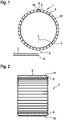
- the Fig. 2 shows the carcass drum in the Fig. 1 in a sectional view. All drum segments are covered circumferentially with a flexible rubber sleeve 12. Only the drum segment 8 is covered above the rubber sleeve 12 with a bonding plate 6. The adhesion sheet 6 is fixed on both sides in each case a groove 11 in the drum segment 8.
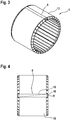
- the Fig. 3 shows the carcass drum 1 from the Fig. 1 in a three-dimensional view.
- the adhesion plate 6 has a rectangular shape and spans only a portion of the rubber boot 12th
- the Fig. 4 shows the carcass drum 1 from the Fig. 3 in a view from the front.
- the dashed line 13 is intended to represent schematically the obliquely cut end portion of the tire inner layer 3.
- the adhesive sheet 6 is fixed laterally with screws 10 on the drum segment 8.
- the Fig. 5 shows a carcass drum with a hexagonal ceremonisblech 7. This adhesive sheet is also located above the rubber sleeve 12 and is fixed laterally with screws on the drum segment 8.
- the Fig. 6 shows the carcass drum from the Fig. 5 with the adhesive sheet 7 in a front view.
- the figure shows the hexagonal shape of the medicinessbleches 7 with the oblique edges 14.
- the oblique edges 14 of the Vietnamesesbleches can compensate when placing the inner tire layer under certain circumstances, the obliquely cut end portion of the tire inner layer.
Landscapes
- Engineering & Computer Science (AREA)
- Mechanical Engineering (AREA)
- Manufacturing & Machinery (AREA)
- Tyre Moulding (AREA)
Abstract
Description
- Die Erfindung betrifft ein Verfahren zur Herstellung eines Fahrzeugreifens.
- Bei konventionellen Fahrzeugreifen ist bekannt die Einlage im Reifenwulst um einen Wulstkern herumzuschlagen. Dadurch wird die Einlage bzw. die Karkasslage fest im Reifenwulst verankert. Solche herkömmlichen Fahrzeugreifen werden dadurch hergestellt, dass zunächst die Innenschicht bzw. Reifeninnenlage und die Einlagen als breite Materiallagen auf einer Reifenaufbautrommel angeordnet werden. Anschließend wird der Wulstkern auf die Einlage gesetzt und das Einlagenende um den Kern herumgeschlagen. Bei der konventionellen Reifenherstellung wird bei einem Verfahrensschritt das Einlagenende von der Reifeninnenseite um den Wulstkern herumgeschlagen. Bei einem zweistufigen Verfahren zur Herstellung von Fahrzeugreifen wird die Reifenkarkasse auf einer separaten Karkasstrommel aufgebaut. Eine solche Karkasstrommel ist in der Regel relativ komplex aufgebaut.
- Der Erfindung liegt die Aufgabe zugrunde, ein verbessertes Verfahren zur Herstellung von Fahrzeugreifen bereitzustellen.
- Gelöst wird die Aufgabe gemäß Anspruch 1 dadurch, dass ein Verfahren mit folgenden Schritten eingesetzt wird:
- a) Positionierung einer Karkasstrommel in einer ersten Wickelposition vor einem ersten Servicer zum Auflegen einer Reifeninnenlage an einer Karkass-Station,
wobei die Karkasstrommel umlaufend mit einer Vielzahl von einzelnen Trommelsegmenten ausgerüstet ist,
wobei alle Trommelsegemente an der Außenseite mit einer umlaufenden flexiblen Gummimanschette überdeckt sind
und wobei die Außenseite der Gummimanschette in einem schmalen Teilbereich mit mindestens einem Haftungsblech mit einer glatten Oberfläche überdeckt ist,
wobei das Haftungsblech an einem der Trommelsegmente montiert ist, - b) Positionierung des vorderen Endes des ersten Servicers mit der Reifeninnenlage an der Karkasstrommel,
wobei die Oberseite des Haftungsbleches gegenüberliegend zum vorderen Ende der Reifeninnenlage positioniert wird, - c) Andrücken des vorderen Endes der Reifeninnenlage an die Oberseite des Haftungsbleches,
wobei das Anhaften der Reifeninnenlage an das Haftungsblech durch die glatte Oberfläche des Haftungsbleches unterstützt wird, - d) Rotieren der Karkasstrommel,
wobei das Aufwickeln der Reifeninnenlage mit der Karkasstrommel erfolgt, - e) Positionierung und Zusammensetzen des hinteren Endes der Reifeninnenlage auf die Oberseite des vorderen Endes der Reifeninnenlage auf der Karkasstrommel,
- f) Aufwickeln von weiteren Reifenbauteilen auf die Karkasstrommel,
- g) Einfahren aller Trommelsegmente in radialer Richtung,
wobei sich der Trommeldurchmesser der Karkasstrommel verkleinert und
wobei mit den Trommelsegmenten und eine Antihaft-Wirkung der Gummimanschette das Ablösen der Innenseite der Reifeninnenlage von der Außenseite der Gummimanschette unterstützt wird, - h) Abnahme der Reifenkarkasse von der Karkasstrommel,
- i) Zusammensetzen der Reifenkarkasse mit einem Gürtel-Laufstreifenpaket an einer Bombiertrommel,
- j) Fertigstellen des Fahrzeugreifens mit weiteren Schritten.
- Ein Vorteil der Erfindung ist insbesondere darin zu sehen, dass durch das Verfahren die Reifeninnenlage mit einer hohen Präzision auf die Karkasstrommel aufgewickelt werden kann. Die Reifeninnenlage wird mit dem Servicer insb. von unten an die Karkasstrommel angelegt, damit die Reifeninnenlage mit einer hohen Genauigkeite aufgewickelt werden kann.
- Das vordere Ende der Reifeninnenlage wird mit dem Servicer gegen die Außenseite des Haftungsbleches gedrückt. Mit dem Haftungsblech mit der glatten Oberseite wird überraschenderweise eine sehr gute Haftwirkung gegenüber dem Gummimaterial der Reifeninnenlage erreicht. Diese Haftwirkung ist notwendig, um die Reifeninnenlage mit einer hohen Präzision auf die Oberseite der Karkasstrommel aufzuwickeln. Bei einer herkömmlichen Karkasstrommel müsste hingegen z. B. die entsprechende Stelle der Gummimanschette z. B. aufgerauht werden, um eine Haftwirkung gegenüber Gummimaterial zu erreichen.
Alle Trommelsegmente sind mit einer Gummimanschette in Umfangsrichtung überspannt.
Vor der Abnahme der Reifenkarkasse von der Karkasstrommel werden alle Trommelsegmente in radialer Richtung eingefahren. Bei diesem Vorgang zieht sich ebenfalls die Gummimanschette zusammen, wodurch das Ablösen der Innenseite der Reifeninnenlage von der Karkasstrommel wesentlich unterstützt wird. - In einer vorteilhaften Weiterbildung der Erfindung ist vorgesehen, dass bei Schritt b) das Anlegen der Reifeninnenlage an der Unterseite der Karkasstrommel erfolgt.
Dadurch kann das vordere Ende der Reifeninnenlage mit einer höheren Präzision an die Karkasstrommel angelegt werden. - In einer weiteren vorteilhaften Weiterbildung der Erfindung ist vorgesehen, dass das Haftungsblech in beiden Randbereichen von einem Trommelsegment in jeweils einer Nut fixiert wird.
Dadurch kann das Haftungsblech auf einfache und sichere Weise am Trommelsegment fixiert werden. - In einer weiteren vorteilhaften Weiterbildung der Erfindung ist vorgesehen, dass bei Schritt b) die Reifeninnenlage mit einem schräg geschnittenen Endabschnitt an die Karkasstrommel angelegt wird.
- Der schräg geschnittene Endabschnitt ist schematisch in der
Figur 4 dargestellt. Mit dem schräg geschnittenen Endabschnitt wird das Zusammensetzen beider Enden der Reifeninnenlage auf der Karkasstrommel verbessert. - In einer weiteren vorteilhaften Weiterbildung der Erfindung ist vorgesehen, dass das Haftungsblech in beiden Randbereichen von einem Trommelsegment mit seitlich angeordneten Schrauben fixiert wird.
Dadurch lässt sich das Haftungsblech auf einfache Weise am Trommelsegment fixieren. - In einer weiteren vorteilhaften Weiterbildung der Erfindung ist vorgesehen, dass das Haftungsblech in der Aufsicht im Wesentlichen rechteckförmig ausgebildet ist,
wobei das Haftungsblech in Umfangsrichtung der Karkasstrommel im Wesentlichen die gleiche Breite aufweist wie die Breite der Trommelsegmente in Umfangsrichtung der Karkasstrommel.
Ein Ausführungsbeispiel für ein rechteckförmiges Haftungsblech ist in denFiguren 3 und 4 dargestellt. - In einer weiteren vorteilhaften Weiterbildung der Erfindung ist vorgesehen, dass das Haftungsblech in der Aufsicht im Wesentlichen sechseckförmig ausgebildet ist, wobei das Haftungsblech in Umfangsrichtung der Karkasstrommel schräg verlaufende Kanten aufweist.
Ein Ausführungsbeispiel für ein sechseckförmiges Haftungsblech ist in denFiguren 5 und 6 dargestellt. Die Form des Haftungsbleches hat insbesondere den Vorteil, dass das vordere Ende der Reifeninnenlage mit einem schrägen Endabschnitt optimal an die Oberseite des Haftungsbleches angelegt werden kann. - In einer weiteren vorteilhaften Weiterbildung der Erfindung ist vorgesehen, dass das Haftungsblech eine Blechdicke von ca. 0,5 bis 1,5 cm aufweist.
Dadurch lässt sich das Haftungsblech auf einfache Weise herstellen und an das jeweilige Trommelsegment anpassen. - Anhand eines Ausführungsbeispieles soll die Erfindung näher erläutert werden. Es zeigt:
- Fig. 1:
- ein Ausführungsbeispiel des Verfahrens
- Fig. 2:
- die Karkasstrommel in der Seitenansicht
- Fig. 3:
- die Karkasstrommel in einer dreidimensionalen Ansicht
- Fig. 4:
- die Karkasstrommel in einer Ansicht von vorne
- Fig. 5:
- eine Karkasstrommel mit einem sechsförmigen Haftungsblech
- Fig. 6:
- die Karkasstrommel in einer Ansicht von vorne
- Die
Figur 1 zeigt eine Seitenansicht der Maschinenanordnung zur Durchführung des Verfahrens.
Die Karkasstrommel 1 ist schematisch dargestellt und umlaufend nicht, wie bei konventionellen Karkasstrommeln üblich, mit einer Gummimanschette überzogen.
Der Servicer 4 mit der Reifeninnenlage 3 befindet sich zunächst in einer Warteposition. Beim Servicer 4 ist nur das vordere Ende schematisch dargestellt. - Auf der Oberseite des Servicers 4 ist die Reifeninnenlage 3 angeordnet. Das Anlegen der Reifeninnenlage 3 an die Karkasstrommel 1 erfolgt an der Unterseite 5 der Karkasstrommel 1. Die Karkasstrommel 1 wird zunächst so gedreht, dass das Haftungsblech 6 gegenüberliegend vom vorderen Ende der Reifeninnenlage 3 angeordnet ist. Alle Trommelsegmente sind mit einer umlaufenden flexiblen Gummimanschette 12 überdeckt. Nur das Trommelsegment 8 ist über der Gummimanschette 12 mit dem Haftungsblech 6 abgedeckt.
Das Haftungsblech 6 besitzt auf der nach außen gerichteten Oberseite eine glatte MetallOberfläche. Das vordere Ende der Reifeninnenlage 3 wird gegen das Haftungsblech 6 gedrückt. Aufgrund der glatten Oberfläche des Haftungsbleches 6 haftet das vordere Ende mit einer hohen Haftwirkung an dem Haftungsblech. - Anschließend rotiert die Karkasstrommel gegen den Uhrzeigersinn und wickelt dabei die Reifeninnenlage 3 vollständig auf die Karkasstrommel 1 auf. Der Servicer 4 wird anschließend wieder in eine Warteposition zurückverfahren. Nachfolgend werden mit weiteren Servicern weitere Reifenbauteile auf die Karkasstrommel 1 aufgewickelt und dabei schrittweise die Reifenkarkasse vervollständigt.
- Vor der Abnahme der Reifenkarkasse von der Karkasstrommel 1 erfolgt ein Einfahren aller Trommelsegmente in radialer Richtung 2, wobei sich der Trommeldurchmesser der Karkasstrommel 1 verkleinert. Die Trommelsegmente weisen auf der Außenseite eine Gummimanschette mit einer Antihaftwirkung gegenüber Gummimaterial auf.
Dadurch wird das Ablösen der Reifeninnenlage von den Trommelsegmenten beim Einfahren der Trommelsegmente wesentlich unterstützt. Die Karkasstrommel weist vorteilhafterweise ca. 24 einzelne Trommelsegmente auf, die gleichmäßig über den Umfang der Karkasstrommel verteilt sind. - Anschließend wird die Reifenkarkasse von der Karkasstrommel 1 abgenommen und zu einer nicht dargestellten Bombiertrommel verfahren. Die Fertigstellung des Fahrzeugreifens erfolgt anschließend mit weiteren Schritten.
- Die
Fig. 2 zeigt die Karkasstrommel in derFig. 1 in einer Schnittansicht. Alle Trommelsegmente sind umlaufend mit einer flexiblen Gummimanschette 12 überdeckt. Nur das Trommelsegment 8 ist oberhalb der Gummimanschette 12 mit einem Haftungsblech 6 überdeckt. Das Haftungsblech 6 ist auf beiden Seiten in jeweils einer Nut 11 im Trommelsegment 8 fixiert. - Die
Fig. 3 zeigt die Karkasstrommel 1 aus derFig. 1 in einer dreidimensionalen Ansicht. Das Haftungsblech 6 besitzt eine rechteckförmige Gestalt und überspannt lediglich einen Teilbereich der Gummimanschette 12. - Die
Fig. 4 zeigt die Karkasstrommel 1 aus derFig. 3 in einer Ansicht von vorne. Die gestrichelte Linie 13 soll schematisch den schräg geschnittenen Endabschnitt der Reifeninnenlage 3 darstellen. Das Haftungsblech 6 wird seitlich mit Schrauben 10 am Trommelsegment 8 fixiert. - Die
Fig. 5 zeigt eine Karkasstrommel mit einem sechseckförmigen Haftungsblech 7. Dieses Haftungsblech liegt ebenfalls über der Gummimanschette 12 und ist seitlich mit Schrauben am Trommelsegment 8 fixiert. - Die
Fig. 6 zeigt die Karkasstrommel aus derFig. 5 mit dem Haftungsblech 7 in einer Ansicht von vorne. Die Figur zeigt die sechseckförmige Gestalt des Haftungsbleches 7 mit den schrägen Kanten 14. Die schrägen Kanten 14 des Haftungsbleches können beim Auflegen der Reifeninnenlage unter Umständen den schräg abgeschnittenen Endabschnitt der Reifeninnenlage kompensieren. -
- 1
- Karkasstrommel
- 2
- Radiale Richtung
- 3
- Reifeninnelage
- 4
- Servicer für Reifeninnenlage
- 5
- Unterseite der Karkasstrommel
- 6
- rechteckförmiges Haftungsblech
- 7
- sechseckförmiges Haftungsblech
- 8
- Trommelsegment für Fixierung des Haltebleches
- 9
- einfaches Trommelsegment
- 10
- Schrauben für Fixierung des Haltebleches
- 11
- Nut für Fixierung des Haltebleches
- 12
- Gummimanschette
- 13
- schräg abgeschnittener Endabschnitt der Reifeninnenlage
- 14
- schräge Kanten des sechseckförmigen Haftungsbleches
Claims (8)
- Verfahren zur Herstellung eines Fahrzeugreifens mit einer Reifenkarkasse, Reifenwülsten mit Kernen, einem Reifengürtel und einem Laufstreifen mit folgenden Schritten:a) Positionierung einer Karkasstrommel (1) in einer ersten Wickelposition vor einem ersten Servicer (4) zum Auflegen einer Reifeninnenlage (3) an einer Karkass-Station, wobei die Karkasstrommel (1) umlaufend mit einer Vielzahl von einzelnen Trommelsegmenten (8, 9) ausgerüstet ist,
wobei alle Trommelsegemente (8, 9) an der Außenseite mit einer umlaufenden flexiblen Gummimanschette (12) überdeckt sind
und wobei die Außenseite der Gummimanschette (12) in einem schmalen Teilbereich mit mindestens einem Haftungsblech (6, 7) mit einer glatten Oberfläche überdeckt ist, wobei das Haftungsblech an einem der Trommelsegmente (8) montiert ist,b) Positionierung des vorderen Endes des ersten Servicers (4) mit der Reifeninnenlage (3) an der Karkasstrommel (1),
wobei die Oberseite des Haftungsbleches (6, 7) gegenüberliegend zum vorderen Ende der Reifeninnenlage (3) positioniert wird, ,c) Andrücken des vorderen Endes der Reifeninnenlage (3) an die Oberseite des Haftungsbleches (6, 7),
wobei das Anhaften der Reifeninnenlage (3) an das Haftungsblech (6, 7) durch die glatte Oberfläche des Haftungsbleches unterstützt wird,d) Rotieren der Karkasstrommel (1),
wobei das Aufwickeln der Reifeninnenlage (3) mit der Karkasstrommel (1) erfolgt,e) Positionierung und Zusammensetzen des hinteren Endes der Reifeninnenlage (3) auf die Oberseite des vorderen Endes der Reifeninnenlage auf der Karkasstrommel (1),f) Aufwickeln von weiteren Reifenbauteilen auf die Karkasstrommel (1),g) Einfahren aller Trommelsegmente(8, 9) in radialer Richtung,
wobei sich der Trommeldurchmesser der Karkasstrommel verkleinert und
wobei mit den Trommelsegmenten(8, 9) und eine Antihaft-Wirkung der Gummimanschette das Ablösen der Innenseite der Reifeninnenlage von der Außenseite der Gummimanschette unterstützt wird,h) Abnahme der Reifenkarkasse von der Karkasstrommel (1),i) Zusammensetzen der Reifenkarkasse mit einem Gürtel-Laufstreifenpaket an einer Bombiertrommel,j) Fertigstellen des Fahrzeugreifens mit weiteren Schritten. - Verfahren nach Anspruch 1,
dadurch gekennzeichnet, dass
bei Schritt b) das Anlegen der Reifeninnenlage an der Unterseite (5) der Karkasstrommel (1) erfolgt. - Verfahren nach einem der vorhergehenden Ansprüche,
dadurch gekennzeichnet, dass
das Haftungsblech (6, 7) in beiden Randbereichen von einem Trommelsegment (8) in jeweils einer Nut fixiert wird. - Verfahren nach einem der vorhergehenden Ansprüche,
dadurch gekennzeichnet, dass
bei Schritt b) die Reifeninnenlage mit einem schräg geschnittenen Endabschnitt an die Karkasstrommel (1) angelegt wird. - Verfahren nach einem der vorhergehenden Ansprüche,
dadurch gekennzeichnet, dass
das Haftungsblech (6, 7) in beiden Randbereichen von einem Trommelsegment (8) mit seitlich angeordneten Schrauben (10) fixiert wird. - Verfahren nach einem der vorhergehenden Ansprüche,
dadurch gekennzeichnet, dass
das Haftungsblech (6) in der Aufsicht im Wesentlichen rechteckförmig ausgebildet ist, wobei das Haftungsblech (6) in Umfangsrichtung der Karkasstrommel (1) im Wesentlichen die gleiche Breite aufweist wie die Breite der Trommelsegmente (8) in Umfangsrichtung der Karkasstrommel (1). - Verfahren nach einem der vorhergehenden Ansprüche,
dadurch gekennzeichnet, dass
das Haftungsblech (7) in der Aufsicht im Wesentlichen sechseckförmig ausgebildet ist, wobei das Haftungsblech (7) in Umfangsrichtung der Karkasstrommel (1) schräg verlaufende Kanten (14) aufweist. - Verfahren nach einem der vorhergehenden Ansprüche,
dadurch gekennzeichnet, dass
das Haftungsblech (6, 7) eine Blechdicke von ca. 0,5 bis 1,5 cm aufweist.
Applications Claiming Priority (1)
| Application Number | Priority Date | Filing Date | Title |
|---|---|---|---|
| DE102016209142.5A DE102016209142A1 (de) | 2016-05-25 | 2016-05-25 | Verfahren zur Herstellung eines Fahrzeugreifens |
Publications (2)
| Publication Number | Publication Date |
|---|---|
| EP3248769A1 true EP3248769A1 (de) | 2017-11-29 |
| EP3248769B1 EP3248769B1 (de) | 2020-10-28 |
Family
ID=58185400
Family Applications (1)
| Application Number | Title | Priority Date | Filing Date |
|---|---|---|---|
| EP17158114.3A Not-in-force EP3248769B1 (de) | 2016-05-25 | 2017-02-27 | Verfahren zur herstellung eines fahrzeugreifens |
Country Status (2)
| Country | Link |
|---|---|
| EP (1) | EP3248769B1 (de) |
| DE (1) | DE102016209142A1 (de) |
Citations (6)
| Publication number | Priority date | Publication date | Assignee | Title |
|---|---|---|---|---|
| JPS60109922U (ja) * | 1983-12-29 | 1985-07-25 | 横浜ゴム株式会社 | タイヤ成形用ゴムブラダ− |
| US5066354A (en) * | 1990-05-25 | 1991-11-19 | Cooper Tire And Rubber Company | Building drum for a tire belt-tread stock package |
| JP2002234081A (ja) * | 2001-02-07 | 2002-08-20 | Yokohama Rubber Co Ltd:The | 帯状ゴム部材の貼り付け方法および成形ドラム |
| DE102007031091A1 (de) * | 2007-07-04 | 2009-01-08 | Continental Aktiengesellschaft | Vorrichtung zum Herstellen eines Fahrzeugreifens mit einer Karkasstrommel |
| WO2010064084A1 (en) * | 2008-12-02 | 2010-06-10 | Pirelli Tyre S.P.A. | Process and apparatus for building tyres for vehicle wheels |
| DE102013103632A1 (de) * | 2013-04-11 | 2014-10-16 | Continental Reifen Deutschland Gmbh | Verfahren zur Herstellung eines Fahrzeugreifens |
-
2016
- 2016-05-25 DE DE102016209142.5A patent/DE102016209142A1/de not_active Withdrawn
-
2017
- 2017-02-27 EP EP17158114.3A patent/EP3248769B1/de not_active Not-in-force
Patent Citations (6)
| Publication number | Priority date | Publication date | Assignee | Title |
|---|---|---|---|---|
| JPS60109922U (ja) * | 1983-12-29 | 1985-07-25 | 横浜ゴム株式会社 | タイヤ成形用ゴムブラダ− |
| US5066354A (en) * | 1990-05-25 | 1991-11-19 | Cooper Tire And Rubber Company | Building drum for a tire belt-tread stock package |
| JP2002234081A (ja) * | 2001-02-07 | 2002-08-20 | Yokohama Rubber Co Ltd:The | 帯状ゴム部材の貼り付け方法および成形ドラム |
| DE102007031091A1 (de) * | 2007-07-04 | 2009-01-08 | Continental Aktiengesellschaft | Vorrichtung zum Herstellen eines Fahrzeugreifens mit einer Karkasstrommel |
| WO2010064084A1 (en) * | 2008-12-02 | 2010-06-10 | Pirelli Tyre S.P.A. | Process and apparatus for building tyres for vehicle wheels |
| DE102013103632A1 (de) * | 2013-04-11 | 2014-10-16 | Continental Reifen Deutschland Gmbh | Verfahren zur Herstellung eines Fahrzeugreifens |
Also Published As
| Publication number | Publication date |
|---|---|
| EP3248769B1 (de) | 2020-10-28 |
| DE102016209142A1 (de) | 2017-11-30 |
Similar Documents
| Publication | Publication Date | Title |
|---|---|---|
| EP0904931B1 (de) | Verfahren und Trommel als Vorrichtung zum Aufbau eines Reifenrohlings | |
| DE1299858B (de) | Reifenrohling zum Aufbau von Fahrzeugluftreifen | |
| DE2708013A1 (de) | Laufflaechenstreifen zur erneuerung von fahrzeugreifen und verfahren zu seiner anbringung | |
| EP2988956A1 (de) | Fahrzeugluftreifen und verfahren zur herstellung eines fahrzeugluftreifens | |
| DE69617473T2 (de) | Verfahren und gerät zum gleichzeitigen zusammensetzen einer vielzahl von reifen | |
| EP2709837B1 (de) | Verfahren zur herstellung eines fahrzeugreifens | |
| DE102019007184A1 (de) | Speichenabdeckung für eine Fahrradfelge | |
| EP3248769B1 (de) | Verfahren zur herstellung eines fahrzeugreifens | |
| EP2687358B1 (de) | Verfahren zur Herstellung von Fahrzeugreifen | |
| DE102007031091A1 (de) | Vorrichtung zum Herstellen eines Fahrzeugreifens mit einer Karkasstrommel | |
| EP2983904B1 (de) | Verfahren und anlage zur herstellung einer karkasse für einen fahrzeugluftreifen | |
| DE102021209826A1 (de) | Verfahren zur Herstellung eines Fahrzeugreifens | |
| EP1954481B1 (de) | Verfahren zum herstellen eines gürtelpakets für einen fahrzeugluftreifens | |
| DE102016209143A1 (de) | Verfahren zur Herstellung eines Fahrzeugreifens | |
| EP3069863B1 (de) | Verfahren zur herstellung von fahrzeugreifen | |
| DE102018209766A1 (de) | Verfahren zur Herstellung eines Fahrzeugreifens | |
| DE102012106465A1 (de) | Verfahren zur Herstellung von Fahrzeugreifen | |
| DE69905600T2 (de) | Reifenkarkasseaufbau und verfahren zu dessen herstellung | |
| DE102015219670A1 (de) | Verfahren zur Herstellung eines Fahrzeugreifens | |
| DE102013109626B4 (de) | Verfahren zur Herstellung eines Fahrzeugreifens | |
| DE102006023007A1 (de) | Verfahren zur Reparatur eines Reifens und hiernach hergestellter Reifen | |
| DE102011050458A1 (de) | Verfahren zur Herstellung eines Fahrzeugreifens | |
| EP2465669A1 (de) | Verfahren zur Herstellung eines Fahrzeugreifens | |
| DE102021209829A1 (de) | Verfahren zur Herstellung eines Fahrzeugreifens | |
| DE102017221044A1 (de) | Karkasstrommel |
Legal Events
| Date | Code | Title | Description |
|---|---|---|---|
| PUAI | Public reference made under article 153(3) epc to a published international application that has entered the european phase |
Free format text: ORIGINAL CODE: 0009012 |
|
| STAA | Information on the status of an ep patent application or granted ep patent |
Free format text: STATUS: THE APPLICATION HAS BEEN PUBLISHED |
|
| AK | Designated contracting states |
Kind code of ref document: A1 Designated state(s): AL AT BE BG CH CY CZ DE DK EE ES FI FR GB GR HR HU IE IS IT LI LT LU LV MC MK MT NL NO PL PT RO RS SE SI SK SM TR |
|
| AX | Request for extension of the european patent |
Extension state: BA ME |
|
| STAA | Information on the status of an ep patent application or granted ep patent |
Free format text: STATUS: REQUEST FOR EXAMINATION WAS MADE |
|
| 17P | Request for examination filed |
Effective date: 20180529 |
|
| RBV | Designated contracting states (corrected) |
Designated state(s): AL AT BE BG CH CY CZ DE DK EE ES FI FR GB GR HR HU IE IS IT LI LT LU LV MC MK MT NL NO PL PT RO RS SE SI SK SM TR |
|
| GRAP | Despatch of communication of intention to grant a patent |
Free format text: ORIGINAL CODE: EPIDOSNIGR1 |
|
| STAA | Information on the status of an ep patent application or granted ep patent |
Free format text: STATUS: GRANT OF PATENT IS INTENDED |
|
| INTG | Intention to grant announced |
Effective date: 20200706 |
|
| GRAS | Grant fee paid |
Free format text: ORIGINAL CODE: EPIDOSNIGR3 |
|
| GRAA | (expected) grant |
Free format text: ORIGINAL CODE: 0009210 |
|
| STAA | Information on the status of an ep patent application or granted ep patent |
Free format text: STATUS: THE PATENT HAS BEEN GRANTED |
|
| AK | Designated contracting states |
Kind code of ref document: B1 Designated state(s): AL AT BE BG CH CY CZ DE DK EE ES FI FR GB GR HR HU IE IS IT LI LT LU LV MC MK MT NL NO PL PT RO RS SE SI SK SM TR |
|
| REG | Reference to a national code |
Ref country code: GB Ref legal event code: FG4D Free format text: NOT ENGLISH |
|
| REG | Reference to a national code |
Ref country code: CH Ref legal event code: EP |
|
| REG | Reference to a national code |
Ref country code: AT Ref legal event code: REF Ref document number: 1327786 Country of ref document: AT Kind code of ref document: T Effective date: 20201115 |
|
| REG | Reference to a national code |
Ref country code: IE Ref legal event code: FG4D Free format text: LANGUAGE OF EP DOCUMENT: GERMAN |
|
| REG | Reference to a national code |
Ref country code: DE Ref legal event code: R096 Ref document number: 502017007895 Country of ref document: DE |
|
| RAP2 | Party data changed (patent owner data changed or rights of a patent transferred) |
Owner name: CONTINENTAL REIFEN DEUTSCHLAND GMBH |
|
| REG | Reference to a national code |
Ref country code: NL Ref legal event code: MP Effective date: 20201028 |
|
| PG25 | Lapsed in a contracting state [announced via postgrant information from national office to epo] |
Ref country code: RS Free format text: LAPSE BECAUSE OF FAILURE TO SUBMIT A TRANSLATION OF THE DESCRIPTION OR TO PAY THE FEE WITHIN THE PRESCRIBED TIME-LIMIT Effective date: 20201028 Ref country code: PT Free format text: LAPSE BECAUSE OF FAILURE TO SUBMIT A TRANSLATION OF THE DESCRIPTION OR TO PAY THE FEE WITHIN THE PRESCRIBED TIME-LIMIT Effective date: 20210301 Ref country code: NL Free format text: LAPSE BECAUSE OF FAILURE TO SUBMIT A TRANSLATION OF THE DESCRIPTION OR TO PAY THE FEE WITHIN THE PRESCRIBED TIME-LIMIT Effective date: 20201028 Ref country code: NO Free format text: LAPSE BECAUSE OF FAILURE TO SUBMIT A TRANSLATION OF THE DESCRIPTION OR TO PAY THE FEE WITHIN THE PRESCRIBED TIME-LIMIT Effective date: 20210128 Ref country code: FI Free format text: LAPSE BECAUSE OF FAILURE TO SUBMIT A TRANSLATION OF THE DESCRIPTION OR TO PAY THE FEE WITHIN THE PRESCRIBED TIME-LIMIT Effective date: 20201028 Ref country code: GR Free format text: LAPSE BECAUSE OF FAILURE TO SUBMIT A TRANSLATION OF THE DESCRIPTION OR TO PAY THE FEE WITHIN THE PRESCRIBED TIME-LIMIT Effective date: 20210129 |
|
| REG | Reference to a national code |
Ref country code: LT Ref legal event code: MG4D |
|
| PG25 | Lapsed in a contracting state [announced via postgrant information from national office to epo] |
Ref country code: ES Free format text: LAPSE BECAUSE OF FAILURE TO SUBMIT A TRANSLATION OF THE DESCRIPTION OR TO PAY THE FEE WITHIN THE PRESCRIBED TIME-LIMIT Effective date: 20201028 Ref country code: BG Free format text: LAPSE BECAUSE OF FAILURE TO SUBMIT A TRANSLATION OF THE DESCRIPTION OR TO PAY THE FEE WITHIN THE PRESCRIBED TIME-LIMIT Effective date: 20210128 Ref country code: IS Free format text: LAPSE BECAUSE OF FAILURE TO SUBMIT A TRANSLATION OF THE DESCRIPTION OR TO PAY THE FEE WITHIN THE PRESCRIBED TIME-LIMIT Effective date: 20210228 Ref country code: LV Free format text: LAPSE BECAUSE OF FAILURE TO SUBMIT A TRANSLATION OF THE DESCRIPTION OR TO PAY THE FEE WITHIN THE PRESCRIBED TIME-LIMIT Effective date: 20201028 Ref country code: PL Free format text: LAPSE BECAUSE OF FAILURE TO SUBMIT A TRANSLATION OF THE DESCRIPTION OR TO PAY THE FEE WITHIN THE PRESCRIBED TIME-LIMIT Effective date: 20201028 Ref country code: SE Free format text: LAPSE BECAUSE OF FAILURE TO SUBMIT A TRANSLATION OF THE DESCRIPTION OR TO PAY THE FEE WITHIN THE PRESCRIBED TIME-LIMIT Effective date: 20201028 |
|
| PG25 | Lapsed in a contracting state [announced via postgrant information from national office to epo] |
Ref country code: HR Free format text: LAPSE BECAUSE OF FAILURE TO SUBMIT A TRANSLATION OF THE DESCRIPTION OR TO PAY THE FEE WITHIN THE PRESCRIBED TIME-LIMIT Effective date: 20201028 |
|
| REG | Reference to a national code |
Ref country code: DE Ref legal event code: R097 Ref document number: 502017007895 Country of ref document: DE |
|
| PG25 | Lapsed in a contracting state [announced via postgrant information from national office to epo] |
Ref country code: RO Free format text: LAPSE BECAUSE OF FAILURE TO SUBMIT A TRANSLATION OF THE DESCRIPTION OR TO PAY THE FEE WITHIN THE PRESCRIBED TIME-LIMIT Effective date: 20201028 Ref country code: SK Free format text: LAPSE BECAUSE OF FAILURE TO SUBMIT A TRANSLATION OF THE DESCRIPTION OR TO PAY THE FEE WITHIN THE PRESCRIBED TIME-LIMIT Effective date: 20201028 Ref country code: LT Free format text: LAPSE BECAUSE OF FAILURE TO SUBMIT A TRANSLATION OF THE DESCRIPTION OR TO PAY THE FEE WITHIN THE PRESCRIBED TIME-LIMIT Effective date: 20201028 Ref country code: SM Free format text: LAPSE BECAUSE OF FAILURE TO SUBMIT A TRANSLATION OF THE DESCRIPTION OR TO PAY THE FEE WITHIN THE PRESCRIBED TIME-LIMIT Effective date: 20201028 Ref country code: CZ Free format text: LAPSE BECAUSE OF FAILURE TO SUBMIT A TRANSLATION OF THE DESCRIPTION OR TO PAY THE FEE WITHIN THE PRESCRIBED TIME-LIMIT Effective date: 20201028 Ref country code: EE Free format text: LAPSE BECAUSE OF FAILURE TO SUBMIT A TRANSLATION OF THE DESCRIPTION OR TO PAY THE FEE WITHIN THE PRESCRIBED TIME-LIMIT Effective date: 20201028 |
|
| PG25 | Lapsed in a contracting state [announced via postgrant information from national office to epo] |
Ref country code: DK Free format text: LAPSE BECAUSE OF FAILURE TO SUBMIT A TRANSLATION OF THE DESCRIPTION OR TO PAY THE FEE WITHIN THE PRESCRIBED TIME-LIMIT Effective date: 20201028 |
|
| PLBE | No opposition filed within time limit |
Free format text: ORIGINAL CODE: 0009261 |
|
| STAA | Information on the status of an ep patent application or granted ep patent |
Free format text: STATUS: NO OPPOSITION FILED WITHIN TIME LIMIT |
|
| PG25 | Lapsed in a contracting state [announced via postgrant information from national office to epo] |
Ref country code: MC Free format text: LAPSE BECAUSE OF FAILURE TO SUBMIT A TRANSLATION OF THE DESCRIPTION OR TO PAY THE FEE WITHIN THE PRESCRIBED TIME-LIMIT Effective date: 20201028 |
|
| 26N | No opposition filed |
Effective date: 20210729 |
|
| GBPC | Gb: european patent ceased through non-payment of renewal fee |
Effective date: 20210227 |
|
| REG | Reference to a national code |
Ref country code: BE Ref legal event code: MM Effective date: 20210228 |
|
| PG25 | Lapsed in a contracting state [announced via postgrant information from national office to epo] |
Ref country code: AL Free format text: LAPSE BECAUSE OF FAILURE TO SUBMIT A TRANSLATION OF THE DESCRIPTION OR TO PAY THE FEE WITHIN THE PRESCRIBED TIME-LIMIT Effective date: 20201028 Ref country code: CH Free format text: LAPSE BECAUSE OF NON-PAYMENT OF DUE FEES Effective date: 20210228 Ref country code: LI Free format text: LAPSE BECAUSE OF NON-PAYMENT OF DUE FEES Effective date: 20210228 Ref country code: LU Free format text: LAPSE BECAUSE OF NON-PAYMENT OF DUE FEES Effective date: 20210227 Ref country code: IT Free format text: LAPSE BECAUSE OF FAILURE TO SUBMIT A TRANSLATION OF THE DESCRIPTION OR TO PAY THE FEE WITHIN THE PRESCRIBED TIME-LIMIT Effective date: 20201028 |
|
| PG25 | Lapsed in a contracting state [announced via postgrant information from national office to epo] |
Ref country code: SI Free format text: LAPSE BECAUSE OF FAILURE TO SUBMIT A TRANSLATION OF THE DESCRIPTION OR TO PAY THE FEE WITHIN THE PRESCRIBED TIME-LIMIT Effective date: 20201028 |
|
| PG25 | Lapsed in a contracting state [announced via postgrant information from national office to epo] |
Ref country code: GB Free format text: LAPSE BECAUSE OF NON-PAYMENT OF DUE FEES Effective date: 20210227 Ref country code: IE Free format text: LAPSE BECAUSE OF NON-PAYMENT OF DUE FEES Effective date: 20210227 |
|
| PG25 | Lapsed in a contracting state [announced via postgrant information from national office to epo] |
Ref country code: IS Free format text: LAPSE BECAUSE OF FAILURE TO SUBMIT A TRANSLATION OF THE DESCRIPTION OR TO PAY THE FEE WITHIN THE PRESCRIBED TIME-LIMIT Effective date: 20210228 |
|
| PG25 | Lapsed in a contracting state [announced via postgrant information from national office to epo] |
Ref country code: BE Free format text: LAPSE BECAUSE OF NON-PAYMENT OF DUE FEES Effective date: 20210228 |
|
| REG | Reference to a national code |
Ref country code: AT Ref legal event code: MM01 Ref document number: 1327786 Country of ref document: AT Kind code of ref document: T Effective date: 20220227 |
|
| PG25 | Lapsed in a contracting state [announced via postgrant information from national office to epo] |
Ref country code: AT Free format text: LAPSE BECAUSE OF NON-PAYMENT OF DUE FEES Effective date: 20220227 |
|
| PG25 | Lapsed in a contracting state [announced via postgrant information from national office to epo] |
Ref country code: HU Free format text: LAPSE BECAUSE OF FAILURE TO SUBMIT A TRANSLATION OF THE DESCRIPTION OR TO PAY THE FEE WITHIN THE PRESCRIBED TIME-LIMIT; INVALID AB INITIO Effective date: 20170227 |
|
| PG25 | Lapsed in a contracting state [announced via postgrant information from national office to epo] |
Ref country code: CY Free format text: LAPSE BECAUSE OF FAILURE TO SUBMIT A TRANSLATION OF THE DESCRIPTION OR TO PAY THE FEE WITHIN THE PRESCRIBED TIME-LIMIT Effective date: 20201028 |
|
| REG | Reference to a national code |
Ref country code: DE Ref legal event code: R081 Ref document number: 502017007895 Country of ref document: DE Owner name: CONTINENTAL REIFEN DEUTSCHLAND GMBH, DE Free format text: FORMER OWNER: CONTINENTAL REIFEN DEUTSCHLAND GMBH, 30165 HANNOVER, DE |
|
| PG25 | Lapsed in a contracting state [announced via postgrant information from national office to epo] |
Ref country code: MK Free format text: LAPSE BECAUSE OF FAILURE TO SUBMIT A TRANSLATION OF THE DESCRIPTION OR TO PAY THE FEE WITHIN THE PRESCRIBED TIME-LIMIT Effective date: 20201028 |
|
| PGFP | Annual fee paid to national office [announced via postgrant information from national office to epo] |
Ref country code: DE Payment date: 20240229 Year of fee payment: 8 |
|
| PGFP | Annual fee paid to national office [announced via postgrant information from national office to epo] |
Ref country code: FR Payment date: 20240221 Year of fee payment: 8 |
|
| PG25 | Lapsed in a contracting state [announced via postgrant information from national office to epo] |
Ref country code: MT Free format text: LAPSE BECAUSE OF FAILURE TO SUBMIT A TRANSLATION OF THE DESCRIPTION OR TO PAY THE FEE WITHIN THE PRESCRIBED TIME-LIMIT Effective date: 20201028 |
|
| REG | Reference to a national code |
Ref country code: DE Ref legal event code: R119 Ref document number: 502017007895 Country of ref document: DE |
|
| PG25 | Lapsed in a contracting state [announced via postgrant information from national office to epo] |
Ref country code: TR Free format text: LAPSE BECAUSE OF FAILURE TO SUBMIT A TRANSLATION OF THE DESCRIPTION OR TO PAY THE FEE WITHIN THE PRESCRIBED TIME-LIMIT Effective date: 20201028 |
|
| PG25 | Lapsed in a contracting state [announced via postgrant information from national office to epo] |
Ref country code: DE Free format text: LAPSE BECAUSE OF NON-PAYMENT OF DUE FEES Effective date: 20250902 |
|
| PG25 | Lapsed in a contracting state [announced via postgrant information from national office to epo] |
Ref country code: FR Free format text: LAPSE BECAUSE OF NON-PAYMENT OF DUE FEES Effective date: 20250228 |