EP3247974B1 - Vorrichtung und verfahren zur messung eines in einem stück geformten ventilsitzes - Google Patents
Vorrichtung und verfahren zur messung eines in einem stück geformten ventilsitzes Download PDFInfo
- Publication number
- EP3247974B1 EP3247974B1 EP16700981.0A EP16700981A EP3247974B1 EP 3247974 B1 EP3247974 B1 EP 3247974B1 EP 16700981 A EP16700981 A EP 16700981A EP 3247974 B1 EP3247974 B1 EP 3247974B1
- Authority
- EP
- European Patent Office
- Prior art keywords
- axis
- slide
- transmission element
- longitudinal axis
- rotary actuator
- Prior art date
- Legal status (The legal status is an assumption and is not a legal conclusion. Google has not performed a legal analysis and makes no representation as to the accuracy of the status listed.)
- Active
Links
Images






Classifications
-
- G—PHYSICS
- G01—MEASURING; TESTING
- G01B—MEASURING LENGTH, THICKNESS OR SIMILAR LINEAR DIMENSIONS; MEASURING ANGLES; MEASURING AREAS; MEASURING IRREGULARITIES OF SURFACES OR CONTOURS
- G01B5/00—Measuring arrangements characterised by the use of mechanical techniques
- G01B5/003—Measuring of motor parts
- G01B5/0032—Valves, actuating devices for valves
-
- F—MECHANICAL ENGINEERING; LIGHTING; HEATING; WEAPONS; BLASTING
- F16—ENGINEERING ELEMENTS AND UNITS; GENERAL MEASURES FOR PRODUCING AND MAINTAINING EFFECTIVE FUNCTIONING OF MACHINES OR INSTALLATIONS; THERMAL INSULATION IN GENERAL
- F16K—VALVES; TAPS; COCKS; ACTUATING-FLOATS; DEVICES FOR VENTING OR AERATING
- F16K37/00—Special means in or on valves or other cut-off apparatus for indicating or recording operation thereof, or for enabling an alarm to be given
- F16K37/0025—Electrical or magnetic means
- F16K37/0041—Electrical or magnetic means for measuring valve parameters
-
- G—PHYSICS
- G01—MEASURING; TESTING
- G01B—MEASURING LENGTH, THICKNESS OR SIMILAR LINEAR DIMENSIONS; MEASURING ANGLES; MEASURING AREAS; MEASURING IRREGULARITIES OF SURFACES OR CONTOURS
- G01B5/00—Measuring arrangements characterised by the use of mechanical techniques
- G01B5/20—Measuring arrangements characterised by the use of mechanical techniques for measuring contours or curvatures
-
- G—PHYSICS
- G01—MEASURING; TESTING
- G01B—MEASURING LENGTH, THICKNESS OR SIMILAR LINEAR DIMENSIONS; MEASURING ANGLES; MEASURING AREAS; MEASURING IRREGULARITIES OF SURFACES OR CONTOURS
- G01B5/00—Measuring arrangements characterised by the use of mechanical techniques
- G01B5/20—Measuring arrangements characterised by the use of mechanical techniques for measuring contours or curvatures
- G01B5/201—Measuring arrangements characterised by the use of mechanical techniques for measuring contours or curvatures for measuring roundness
-
- G—PHYSICS
- G01—MEASURING; TESTING
- G01B—MEASURING LENGTH, THICKNESS OR SIMILAR LINEAR DIMENSIONS; MEASURING ANGLES; MEASURING AREAS; MEASURING IRREGULARITIES OF SURFACES OR CONTOURS
- G01B5/00—Measuring arrangements characterised by the use of mechanical techniques
- G01B5/24—Measuring arrangements characterised by the use of mechanical techniques for measuring angles or tapers; for testing the alignment of axes
- G01B5/241—Measuring arrangements characterised by the use of mechanical techniques for measuring angles or tapers; for testing the alignment of axes for measuring conicity
Definitions
- the present invention refers to a device and a method for measuring a valve seat formed in a piece.
- the invention relates to a device and a method for measuring a profile of a seat formed in a piece.
- the device and the method according to the invention are targeted to measure a tapered portion of the seat located at the mouth of the seat.
- the invention applies in particular, but not exclusively, to the measurement of the valve seat of an internal combustion engine, formed in the cylinder head.
- Such valve seat defines a seat axis, more specifically the valve seat has a guide hole, defining such seat axis, and the tapered portion is inclined at an angle (for example 45 degrees) with respect to the seat axis.
- Some parameters of the tapered portion of the seat are to be measured, in particular parameters related to the inclination angle of the tapered portion (with respect to the guide hole and to the surfaces adjacent to the tapered portion, which have different taper), to the straightness of the tapered portion and to its length, as well as to an oscillation of the profile of the tapered portion (runout) and to the roundness of the tapered portion.
- Such devices are known for measuring said valve seats, for example from patent documents US5533384A , DD137970 , EP2330378A1 and DE10121964B4 .
- Such devices have an elongate shape defining a longitudinal axis, that is a shape that is elongated along such longitudinal axis, so as to be arranged to properly cooperate with the seat to be measured and are equipped with a sensor adapted to detect the profile of the tapered portion of the valve seat.
- the sensor In order to be able to scan the tapered portion of the valve seat in its length, the sensor must be able to radially move, for cooperating with areas of the tapered portion positioned at different distances from the seat axis.
- the solution proposed by EP2330378A1 provides that the sensor is mounted on an oscillating element.
- this solution has the limitation of being not always sufficiently precise and reliable in terms of repeatability in the measurement and robustness.
- the sensor is mounted on a slide movable along a guide, the latter being arranged parallel to the surface of the valve seat to be measured.
- the slide is moved by a motor having its axis of rotation aligned with the guide. Therefore, the device of DE10121964B4 has a portion that protrudes and is inclined, for example of an angle of 45 degrees, with respect to the longitudinal axis of the device.
- the slide with the respective sensor and the motor responsible for moving the slide are housed in the protruding and inclined portion.
- This solution has the disadvantage of making the device bulky.
- a ending portion of the device, at which the sensor is arranged has a relatively large radial dimension that prevents the device to be used in particular operating conditions, for example, where the cylinder head including the valve seat to be measured is mounted on a support which defines a narrow passage, through which the device should be introduced to reach the valve seat.
- the object of the present invention is to get a device and a method for measuring a valve seat formed in a piece, which overcome the drawbacks of the above-cited prior art.
- a further object of the present invention is to get a device and a method for measuring a seat, that allow the user to save time, allowing it to measure all parameters of interest by means of the same device. Said objects are fully achieved by the device and the method according to the present invention, which are characterized by the contents of the claims below.
- the device according to the present description is a device for measuring a seat, in particular a valve seat formed in a workpiece, in particular formed in a cylinder head of an internal combustion engine.
- the device is particularly targeted to measure a tapered portion of the valve seat.
- the device is elongate and define a longitudinal axis, that is it has a shape that is elongated along said longitudinal axis.
- the device comprises an inclined guide (for example, 45 degrees inclined) with respect to the longitudinal axis of the device and a slide slidably coupled to the guide to move (by translation) in a scanning direction defined by the guide and inclined with respect to the longitudinal axis.
- the slide is preloaded with constant load by a leaf spring that eliminates backlash ensuring the reliability of measurement.
- the device also includes a sensor mounted on the slide and configured to detect a profile of the seat; or, for sensing at least one parameter relating to the profile of the seat.
- the sensor is intended to detect the profile of the tapered portion of the seat.
- the sensor includes for example a movable feeler connected to a transducer of a known type, or is a contactless inductive or optical sensor. In any case, the present technical solution is not limited to the type of sensor used.
- the device also comprises, preferably, a processing unit connected to the sensor.
- the processing unit is configured to receive data detected by the sensor, acquire and process such data. Alternatively, the processing unit may be remote, instead of being on board of the device.
- the device comprises a rotary actuator, that defines a longitudinal rotation axis and is kinematically connected to the slide to move it along the guide.
- the rotary actuator is oriented substantially parallel to the longitudinal axis of the device, more specifically the longitudinal rotation axis and the longitudinal axis of the device are substantially parallel to each other.
- the rotary actuator is aligned with (or coaxial to) the longitudinal axis of the device.
- the device also comprises a transmission assembly interposed between the rotary actuator and the slide, for transforming a rotary motion generated by the rotary actuator around a longitudinal rotation axis of the rotary actuator in a reciprocating linear motion of the slide along the scanning direction. Placing the rotary actuator out of line with the scanning direction renders the device particularly compact in the radial dimension, that is the device features an elongate and spindly shape along the longitudinal axis thereof, in particular at an ending zone of the device at which the sensor is arranged, thus facilitating the use even in situations of limited accessibility of the valve seat to be measured.
- the transmission assembly comprises a first transmission element, rotatable about the longitudinal rotation axis of the rotary actuator, and a second transmission element, configured to oscillate about an axis perpendicular to a plane parallel to the scanning direction and containing the longitudinal axis of the device.
- the rotary actuator is coupled to the first transmission element to cause a rotary or oscillatory rotary motion of the latter about the longitudinal rotation axis of the rotary actuator; while the second transmission element transmits a reciprocating linear motion to the slide.
- the second transmission element is a rocker arm having a manoeuvring projection movably coupled to the slide (to define a joint).
- the device comprises a lever having a first end kinematically connected to the first transmission element and a second end pivoted to the second transmission element.
- the lever serves as manoeuvring element of the second transmission element.
- the lever is arranged along an axis substantially parallel to the longitudinal axis of the device. This is functional to its elongate and spindly shape.
- the device also comprises a support structure, to which the rotary actuator is fixed and to which the second transmission element is pivoted.
- Two embodiments of the first transmission element of the transmission assembly are provided.
- the first transmission element is a pin eccentric with respect to the longitudinal rotation axis of the rotary actuator.
- the device, more specifically the transmission assembly also comprises a bracket, that is configured to oscillate about an axis parallel to the oscillating axis of the second transmission element and movably coupled to the eccentric pin so as to receive an oscillating movement.
- the bracket is also pivoted to the first end of the lever (that as a consequence is kinematically connected to the first transmission element).
- the bracket is pivoted to the support structure.
- the supporting structure, the bracket, the lever and the second transmission element define an articulated quadrilateral, or articulating four-bar linkage.
- the coupling between the eccentric pin and the bracket defines a joint in which the eccentric pin serves as a crank, and the pin is coupled to a slot of the bracket.
- the coupling of the eccentric pin to the groove of the bracket allows relative movement between pin and groove according to three degrees of freedom of movement: (i) along a direction along which the groove is arranged, (ii) toward and away from a the bottom wall of the groove, and (iii) by inclination of an axis (a longitudinal axis) of the eccentric pin with respect to a direction defined by side walls of the groove (this direction varies depending on the position of the eccentric pin, thus determining the oscillation of the bracket) .
- the first transmission element is a worm screw.
- the transmission assembly comprises a cursor, connected to a free end of the worm screw so as to be longitudinally translatable with a straight-line reciprocating motion.
- the cursor is pivoted to the first end of the lever.
- the cursor is guided to longitudinally slide along a portion of the support structure.
- the sensor mounted on the slide allows to measure parameters related to the angles, the straightness and length of the tapered portion of the seat.
- the rotary actuator, the slide provided with the sensor, the guide and the transmission assembly be part of a movable unit rotatably mounted on a stationary body of the device.
- the device also comprises a motor housed in the stationary body and connected to the movable arm for causing it to rotate, preferably around the longitudinal axis of the device.
- the movable unit also includes a stem that is longitudinally oriented and protrudes from one end of the device opposite to the stationary body. This allows to measure, with the same device, also the parameters of a guide hole of the valve.
- the movable unit comprises a hollow cylinder, interposed between the stationary body and the stem. The hollow cylinder internally houses the rotary actuator and the transmission assembly. This makes the device particularly robust, despite its elongate and spindly shape.
- the stem is coaxial to the axis of rotation of the movable unit and to the longitudinal rotation axis of the rotary actuator and to an axis of the hollow cylinder.
- the present description also provides a method for measuring a valve seat formed in a piece, the valve seat defining a seat axis, by means of a device elongate along a longitudinal axis and having a sensor configured to measure a parameter related to a profile of the valve seat, and a processing unit for receiving data detected by the sensor.
- the method comprises a preliminary step of positioning the device alongside the seat to be measured with its longitudinal axis aligned to the seat axis.
- the method comprises a step of moving the sensor, by means of a slide, by translation in a scanning direction that is inclined with respect to said longitudinal axis.
- the displacement of the sensor along the scanning direction includes a generation of a rotary motion around the longitudinal axis of the device by means of a rotary actuator and a transformation of said rotary motion into a reciprocating linear motion of the slide along the scanning direction, by means of a transmission assembly that is kinematically interposed between the rotary actuator and the slide.
- the rotary motion around said longitudinal axis is transformed into an oscillatory motion of at least one second transmission element of the transmission assembly around an axis perpendicular to a plane parallel to the scanning direction and containing the longitudinal axis of the device.
- the transformation of rotary motion about the longitudinal axis in said oscillatory motion there are provided two alternative embodiments (corresponding to the embodiments described above in connection with the device).
- the transformation of the rotary motion about the longitudinal axis into said oscillatory motion is performed by an interaction between a pin that is eccentric with respect to the longitudinal rotation axis of the rotary actuator and a bracket that is constrained to oscillate about an axis perpendicular to a plane parallel to the scanning direction and containing the longitudinal rotation axis of the rotary actuator.
- the transformation of the rotary motion about the longitudinal axis in said oscillatory motion is realized by an interaction between a worm screw and a cursor that is constrained to translate along the longitudinal rotation axis of the rotary actuator.
- the cursor is kinematically coupled to a second transmission element configured to oscillate about an axis perpendicular to a plane parallel to the scanning direction and containing the longitudinal axis of the device.
- the method also includes a step of rotation, about said longitudinal axis of the device, of a movable unit comprising the slide, the sensor and the rotary actuator.
- a transmission assembly for translating a sensor along a scanning direction in a device for measuring a valve seat formed in a piece, wherein the device has an elongate shape and defines a longitudinal axis, that is the device is elongated along the longitudinal axis, and the scanning direction is inclined (for example, 45 degrees inclined) with respect to said longitudinal axis.
- the present description also refers to a method for translating a sensor along a scanning direction in a device for measuring a valve seat formed in a piece, wherein the device is elongated along a longitudinal axis, that is it has an elongate shape that defines the longitudinal axis, and the scanning direction is inclined (for example 45 degrees inclined, or other angle, for example comprised between 20 and 80 degrees) with respect to said longitudinal axis.
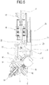
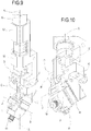
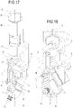
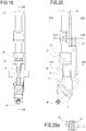
- the numeral 1 indicates a device for measuring a valve seat formed in a piece and defining a seat axis.
- the device 1 is elongated along a longitudinal axis A, that is it has an elongate shape defining the longitudinal axis A.
- the device 1 comprises a stationary body 2, which houses a motor (not shown, of a type in itself known, for example, a brushless motor) is housed.
- the device 1 also comprises a movable unit 3, coupled to the stationary body 2 so as to rotate about the longitudinal axis A; the movable unit 3 is placed in rotation by said motor. Therefore, during the rotation of the movable unit 3, the body 2 remains stationary.
- the movable unit 3 also includes a hollow cylinder 4 and a ferrule 5.
- the ferrule comprises a stem 6 and a connection element 7, the latter being adapted to be coupled to the hollow cylinder 4.
- the stem 6 is protruding from the connection element 7 and extends along the longitudinal axis A.
- the connection element 7 defines a groove 8; the groove 8 extends along a plane passing through the longitudinal axis A of the device 1.
- the device 1 also includes a measuring unit adapted in particular for measuring a tapered portion of the seat to be measured. Said measuring unit is housed inside the hollow cylinder 4 and the groove 8 of the connection element 7. Therefore, the measuring units forms part of the movable unit 3.
- Such a measuring unit is the main subject of the present invention and of the description that follows.
- the device i.e. the measuring unit; this expression here in brackets will be omitted below for brevity
- the sensor (that is a contact probe in the embodiment shown in the drawings) is configured to measure a parameter related to a profile of the seat.
- the sensor 10 is connected to a processing unit (not shown, of a type in itself known, for example comprising a processor, or a circuit board or other element configured to receive and process data and / or signals).
- the slide 9 is slidably coupled to the guide 11 to translate in a scanning direction, or scanning axis, B inclined with respect to the longitudinal axis A.
- the scanning axis B is operatively arranged within the groove 8 of the connection element 7.
- the guide 11 is fixed to a support structure 12 (of the measuring unit).
- the device also includes a rotary actuator 13 (for example, a brushless motor) that is connected to the support structure 12 and defines a longitudinal rotation axis.
- the rotary actuator 13 is oriented substantially parallel to the longitudinal axis A of the device 1, more specifically the longitudinal rotation axis of the rotary actuator 13 is substantially parallel, and preferably aligned to, the longitudinal axis A of the device.
- the device 1 comprises a transmission assembly interposed (i.e. kinematically interconnected) between the rotary actuator 13 and the slide 9, for transforming a rotary motion about the longitudinal axis A of the actuator in a reciprocating linear motion of the slide along the scanning direction B.
- the slide 9 defines, in an inner portion opposite to that from which the sensor 10 protrudes, an abutment wall 14 inclined with respect to the scanning direction B.
- the abutment wall 14 is cooperating with an auxiliary sensor 15 (for example with a retractable feeler of the sensor 15, operatively active against the abutment wall 14, like a cam follower cooperating with a cam), to make available a parameter representative of a position of the slide 9 along the guide 11.
- the processing unit is adapted to receive a signal from the auxiliary sensor 15.
- the processing unit is programmed to acquire, in a plurality of instants of acquisition, a corresponding plurality of pairs of values, wherein each pair comprises a value of the signal detected by the sensor 10 and a value of the signal detected by the auxiliary sensor 15.
- the processing unit is connected to the rotary actuator 13 for driving it.
- the processing unit is programmed to drive the rotary actuator 13 as a function of a predetermined (preset) displacement to the sensor 10 along the scanning axis B.
- the processing unit is programmed to use the signal received from the auxiliary sensor 15 as a control signal, for driving the rotary actuator 13.
- the processing unit is programmed for processing the control signal received from the auxiliary sensor 15 and for generating a driving signal, for controlling the rotary actuator 13 as a function of said control signal.
- the processing unit is also connected to the motor for rotating the movable unit 3.
- the processing unit is programmed to generate an additional drive signal for controlling said motor.
- the processing unit is programmed to generate said additional drive signal for said motor as a function of said control signal and / or the signal generated by the sensor 10.
- the device 1 (in particular, the transmission assembly) comprises a first transmission element, rotatable about the longitudinal rotation axis of the rotary actuator 13 (preferably coincident with the longitudinal axis A of the device 1).
- the device 1 (in particular, the transmission assembly) comprises a second transmission element, configured to oscillate about an axis C perpendicular to a plane, wherein said plane is parallel to the scanning direction B, and contains the longitudinal axis A of the device (i.e. the longitudinal rotation axis of the rotary actuator 13).
- the second transmission element is a rocker arm 16 pivoted to the support structure 12 to swing about the axis C.
- the rocker arm 16 has a manoeuvring projection 17 movably coupled to the slide.
- the manoeuvring projection 17 is operatively and movably inserted in a recess 91 of the slide 9.
- the manoeuvring projection 17 is shaped as a hub; the manoeuvring protrusion 17 has one end at least partially spherical.
- the manoeuvring protrusion 17 is movably engaged in the recess 91 of the slide 9 to be able to move relative thereto for rotation (due to the oscillation), and varying a distance with respect to a bottom wall of the recess 91.
- the roles of male and female in the coupling between the manoeuvring projection 17 and the slide 9 can be mutually exchanged.
- the device 1 in particular, the transmission assembly
- the lever 18 is elongate along an axis and has a first and a second end.
- the first end of the lever 18 is kinematically connected to the first transmission element and the second end of the lever 18 is pivoted to the rocker arm 16. It is observed that the lever axis 18 is arranged substantially parallel to the longitudinal axis A of the device.
- the first transmission element is connected to the rotary actuator 13 by means of a joint 19 that is preferably supported by bearings 20. This increases the accuracy of the device and contributes to get it in an elongated shape along the longitudinal axis A.
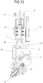
- the present description presents two examples of embodiment; the first example is shown in Figure 2 (and in the figures related to it), the second example is shown in Figures 25 and 26 .
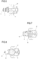
- the first transmission element is a pin 21 eccentric with respect to the longitudinal rotation axis of the rotary actuator 13.
- the transmission assembly comprises a bracket 22 that is configured to oscillate about an axis D parallel to the oscillation axis C of the rocker arm 16.
- the axis D intersects the longitudinal axis A of the device.
- the bracket 22 is hinged to the support structure 12 to swing about the axis D.
- the bracket 22 defines a slot 23 that receives the eccentric pin 21 and is movably coupled to the latter so as to receive the oscillating movement. More specifically, displacements of the pin 21 along a circular path about the longitudinal rotation axis of the rotary actuator 13 (that is, according to the preferred embodiment, about the longitudinal axis A of the device 1) cause oscillating movements of the bracket 22.
- the first end of the lever 18 is pivoted to the bracket 22.
- the bracket 22 comprises a finger 24 configured to cooperate with a reference sensor 25 (for example an inductive sensor) for defining an initial reference position for the rotary actuator 13.
- the reference sensor 25 is oriented along an axis parallel to the longitudinal axis A of the device 1.
- the axis D about which the bracket 22 oscillates is interposed between the finger 24 and the portion of the bracket 22 that is pivoted to the lever 18 , whereby, when the lever 18 moves longitudinally in one direction, the finger 24 moves longitudinally in the opposite direction.
- the bracket 22 is swung; the bracket 22 thus moves the lever 18 along a substantially longitudinal direction (the lever 18 constitutes one side of an articulated quadrilateral or four-bar linkage, together with the bracket 22, the support structure 12 and the rocker arm 16), alternately in one direction and in the other; thus, the lever 18 causes the rocker arm 16 to oscillate, and the latter, through the manoeuvring projection 17, causes the slide 9 to translate along the guide 11.
- the first transmission element is a worm screw 26.
- the transmission assembly comprises a cursor 27, connected to a free end of the worm screw 26 so as to be longitudinally translatable with rectilinear motion (in both directions, as a function of a direction of rotation of the rotary actuator 13).
- the cursor 27 is guided on the support structure 12.
- the cursor 27, in its straight-line reciprocating motion is cooperating with the reference sensor 25 for defining the initial reference position for the rotary actuator 13.
- the second end of the lever 18 is pivoted to the cursor 27.
- the worm screw 26 is caused to turn about its axis and, as a consequence, the cursor 27 longitudinally translates and pulls the lever 18 in its straight-line reciprocating motion.
- the lever 18 causes the rocker arm 16 to oscillate, and the latter, through the manoeuvring projection 17, causes the slide 9 to translate along the guide 11.
- the sense of rotation of the actuator 13 must be periodically inverted in order to cause the oscillation of the rocker arm 16. Therefore, the invention renders available a method to move the sensor 10 for translation along the scanning direction B, as part of a method for measuring a valve seat formed in a piece.
- This method comprises a step of causing a rotary motion, more specifically a rotary motion of the first transmission element, about the longitudinal rotation axis - that is parallel to and preferably aligned to said longitudinal axis A - by means of the rotary actuator 13, and a step of transforming said rotary motion into a reciprocating linear motion of the slide 9 along the scanning direction B.
- said rotary motion around said longitudinal axis A is first converted into an oscillatory motion around an axis C perpendicular to a plane parallel to the scanning direction B and containing the longitudinal rotation axis of the rotary actuator 13.
- the transformation of the rotary motion about the longitudinal rotation axis i. e.
- the longitudinal axis A, into said oscillatory motion is achieved by means of the interaction of the eccentric pin 21 with the bracket 22, the latter being constrained to oscillate about an axis D perpendicular to a plane parallel to the scanning direction and containing the longitudinal rotation axis of the rotary actuator, wherein the axis D is parallel to the oscillation axis C of the rocker arm 16.
- the transformation of the rotary motion into the oscillatory motion is achieved by means of the interaction of the worm screw 26 and the cursor 27, the latter being constrained to translate along the longitudinal rotation axis of the rotary actuator 13, in which the cursor 27 is kinematically coupled to the rocker arm 16 oscillating about the axis C by means of the lever 18.
Landscapes
- Physics & Mathematics (AREA)
- General Physics & Mathematics (AREA)
- Engineering & Computer Science (AREA)
- General Engineering & Computer Science (AREA)
- Mechanical Engineering (AREA)
- A Measuring Device Byusing Mechanical Method (AREA)
- Length Measuring Devices With Unspecified Measuring Means (AREA)
Claims (13)
- Vorrichtung (1) zur Messung eines Ventilsitzes in einem Bauteil, wobei die Vorrichtung (1) entlang einer Längsachse (A) langgestreckt ist und Folgendes umfasst:- einen Schlitten (9) und eine Führung (11), wobei der Schlitten (9) zur translatorischen Bewegung in einer Abtastrichtung (B), die bezüglich der Längsachse (A) geneigt ist, verschiebbar mit der Führung (11) gekoppelt ist;- einen Sensor (10), der an dem Schlitten (9) angebracht und dazu konfiguriert ist, einen einem Profil des Ventilsitzes entsprechenden Parameter zu messen;- eine Verarbeitungseinheit, die mit dem Sensor (10) verbunden ist;- einen Drehantrieb (13), der eine Längsdrehachse definiert und zur Bewegung des Schlittens (9) entlang der Führung (11) kinematisch mit dem Schlitten (9) verbunden ist;dadurch gekennzeichnet,
dass die Längsdrehachse des Drehantriebs (13) im Wesentlichen parallel zur Längsachse (A) der Vorrichtung (1) verläuft und dass die Vorrichtung (1) eine Kraftübertragungsanordnung umfasst, die zwischen dem Drehantrieb (13) und dem Schlitten (9) eingefügt ist, um eine Drehbewegung um die Längsdrehachse des Drehantriebs (13) in eine lineare Schwingbewegung des Schlittens (9) entlang der Abtastrichtung (B) umzuwandeln, wobei die Kraftübertragungsanordnung Folgendes umfasst:- ein erstes Kraftübertragungselement (21, 26), das um die Längsdrehachse des Drehantriebs (13) drehbar ist, und- ein zweites Kraftübertragungselement (16, 17), das dazu konfiguriert ist, um eine Achse (C), die senkrecht zu einer parallel zu der Abtastrichtung (B) verlaufenden und die Längsachse (A) der Vorrichtung (1) enthaltenden Ebene verläuft, zu schwingen - Vorrichtung (1) nach Anspruch 1, wobei die Kraftübertragungsanordnung einen Hebel (18) mit einem ersten Ende, das kinematisch mit dem ersten Kraftübertragungselement verbunden ist, und einem zweiten Ende, das an dem zweiten Kraftübertragungselement geschwenkt ist, umfasst, wobei der Hebel (18) entlang einer Achse angeordnet ist, die im Wesentlichen parallel zu der Längsachse (A) der Vorrichtung (1) verläuft.
- Vorrichtung nach Anspruch 2, wobei das zweite Kraftübertragungselement ein Kipphebel (16) ist, der einen Betätigungsüberstand (17) aufweist, welcher beweglich mit dem Schlitten (9) gekoppelt ist.
- Vorrichtung nach Anspruch 2 oder 3, wobei das erste Kraftübertragungselement ein Bolzen (21) ist, der bezüglich der Längsdrehachse des Drehantriebs (13) exzentrisch ist.
- Vorrichtung nach Anspruch 4, wobei die Kraftübertragungsanordnung einen Halter (22) umfasst, der dazu konfiguriert ist, um eine Achse (D) zu schwingen, die parallel zu der Schwingachse (C) des zweiten Kraftübertragungselements verläuft und beweglich mit dem exzentrischen Bolzen (21) gekoppelt ist, um eine Schwingbewegung aufzunehmen, wobei das erste Ende des Hebels (18) an dem Halter (22) geschwenkt ist.
- Vorrichtung nach Anspruch 5, die ferner einen Referenzsensor (25) aufweist, wobei der Halter (22) einen Finger (24) umfasst, der dazu konfiguriert ist, mit dem Referenzsensor (25) zur Definition einer Anfangsreferenzposition für den Drehantrieb (13) zusammenzuwirken.
- Vorrichtung nach Anspruch 2 oder 3, wobei das erste Kraftübertragungselement eine Schneckenschraube (26) ist.
- Vorrichtung nach Anspruch 7, wobei die Kraftübertragungsanordnung einen Schieber (27) umfasst, der mit einem freien Ende der Schneckenschraube (26) verbunden ist, um in Längsrichtung mit einer geradlinigen Hin- und Herbewegung translatorisch beweglich zu sein, wobei das erste Ende des Hebels (18) an dem Schieber (27) geschwenkt ist.
- Vorrichtung nach einem der vorhergehenden Ansprüche, umfassend:- einen feststehenden Körper (2);- eine bewegliche Einheit (3), die dahingehend mit dem feststehenden Körper (2) gekoppelt ist, sich um die genannte Längsachse (A) der Vorrichtung (1) zu drehen;- einen Motor zum Drehen der beweglichen Einheit (3) bezüglich des stationären Körpers (2),wobei die bewegliche Einheit (3) den Schlitten (9), den Sensor (10), den Drehantrieb (13) und die Kraftübertragungsanordnung umfasst.
- Verfahren zur Messung eines Ventilsitzes in einem Bauteil, wobei der Ventilsitz eine Sitzachse definiert, das die folgenden Schritte umfasst:- Herstellen einer entlang einer Längsachse (A) langgestreckten Vorrichtung (1), die einen Sensor (10) aufweist, der dazu konfiguriert ist, einen Parameter bezüglich eines Profils des Ventilsitzes zu messen, und einer Verarbeitungseinheit zum Empfangen von durch den Sensor (10) detektierten Daten;- Positionieren der Vorrichtung (1) neben den Sitz mit auf die Sitzachse ausgerichteter Längsachse (A);- Bewegen des an einem Schlitten (9) angebrachten Sensors (10) durch translatorische Bewegung in einer Abtastrichtung (B), die bezüglich der Längsachse (A) der Vorrichtung (1) geneigt ist,dadurch gekennzeichnet, dass der Schritt des Bewegens des Sensors (10) die folgenden Schritte umfasst:- Bewirken einer Drehbewegung eines ersten Kraftübertragungselements (21, 26) um eine Längsdrehachse, die parallel zu der Längsachse (A) verläuft, mittels eines Drehantriebs (13);- Umwandeln der Drehbewegung des ersten Kraftübertragungselements (21, 26) in eine Schwingbewegung eines zweiten Kraftübertragungselements (16, 17) um eine Achse (C), die senkrecht zu einer parallel zu der Abtastrichtung (B) verlaufenden und die Längsachse (A) der Vorrichtung enthaltenden Ebene verläuft, um die Drehbewegung des ersten Kraftübertragungselements (21, 26) in eine lineare Hin- und Herbewegung des Schlittens (9) entlang der Abtastrichtung (B) umzuwandeln.
- Verfahren nach Anspruch 10, wobei der Schritt des Umwandelns der Drehbewegung um die Längsdrehachse in die Schwingbewegung ein Zusammenwirken eines Bolzens (21), der Teil des ersten Kraftübertragungselements ist und bezüglich der Längsdrehachse (A) des Drehantriebs (13) exzentrisch ist, und eines Halters (22), der zum Schwingen um eine Achse (D), die senkrecht zu einer parallel zu der Abtastrichtung (B) verlaufenden und die Längsachse (A) enthaltenden Ebene verläuft, eingeschränkt ist, beinhaltet.
- Verfahren nach Anspruch 10, wobei der Schritt des Umwandelns der Drehbewegung um die Längsdrehachse in die Schwingbewegung ein Zusammenwirken einer Schneckenschraube (26) und eines Schiebers (27), der zur translatorischen Bewegung entlang der Längsdrehachse des Drehantriebs (13) eingeschränkt ist, beinhaltet, wobei der Schieber (27) kinematisch mit dem zweiten Kraftübertragungselement gekoppelt ist, das um eine Achse (C) geschwungen wird, die senkrecht zu einer parallel zu der Abtastrichtung (B) verlaufenden und die Längsachse (A) enthaltenden Ebene verläuft.
- Verfahren nach einem der Ansprüche 10 bis 12, ferner umfassend einen Schritt des Drehens einer beweglichen Einheit (3), die den Schlitten (9), den Sensor (10) und den Drehantrieb (13) umfasst, um die Längsachse (A).
Applications Claiming Priority (2)
| Application Number | Priority Date | Filing Date | Title |
|---|---|---|---|
| ITBO20150018 | 2015-01-19 | ||
| PCT/EP2016/050918 WO2016116411A1 (en) | 2015-01-19 | 2016-01-18 | Device and method for measuring a valve seat formed in a piece |
Publications (2)
| Publication Number | Publication Date |
|---|---|
| EP3247974A1 EP3247974A1 (de) | 2017-11-29 |
| EP3247974B1 true EP3247974B1 (de) | 2020-09-09 |
Family
ID=52574232
Family Applications (1)
| Application Number | Title | Priority Date | Filing Date |
|---|---|---|---|
| EP16700981.0A Active EP3247974B1 (de) | 2015-01-19 | 2016-01-18 | Vorrichtung und verfahren zur messung eines in einem stück geformten ventilsitzes |
Country Status (7)
| Country | Link |
|---|---|
| US (1) | US10295326B2 (de) |
| EP (1) | EP3247974B1 (de) |
| KR (1) | KR102480262B1 (de) |
| CN (1) | CN107208995B (de) |
| DE (1) | DE202015004182U1 (de) |
| ES (1) | ES2828983T3 (de) |
| WO (1) | WO2016116411A1 (de) |
Families Citing this family (5)
| Publication number | Priority date | Publication date | Assignee | Title |
|---|---|---|---|---|
| US8612314B2 (en) | 2008-09-09 | 2013-12-17 | Truecar, Inc. | System and method for the utilization of pricing models in the aggregation, analysis, presentation and monetization of pricing data for vehicles and other commodities |
| CN110332877A (zh) * | 2019-07-05 | 2019-10-15 | 神龙汽车有限公司 | 一体式电子缸盖阀座密封线深度测量装置 |
| CN111408945B (zh) * | 2020-04-30 | 2024-10-25 | 杭州中久自控系统有限公司 | 燃气比例阀装配设备 |
| KR102795529B1 (ko) * | 2022-03-17 | 2025-04-18 | 삼공기어공업(주) | 피니언 기어용 런아웃 테스트 장치 |
| KR102752607B1 (ko) * | 2022-03-17 | 2025-01-14 | 삼공기어공업(주) | 링기어용 런아웃 테스트 장치 |
Family Cites Families (13)
| Publication number | Priority date | Publication date | Assignee | Title |
|---|---|---|---|---|
| DD137970A1 (de) | 1978-07-26 | 1979-10-03 | Klaus Henze | Vorrichtung zur ermittlung des ventileinschlages an dieselmotoren |
| JPS5926411B2 (ja) * | 1981-03-07 | 1984-06-27 | 本田技研工業株式会社 | 内燃機関のバルブガイド穴とバルブシ−ト面の加工方法ならびにその装置 |
| US5302057A (en) * | 1990-09-28 | 1994-04-12 | Serdi-Societe D'etudes De Realisation Et De Diffusion Industrielles | Method and device for centering a guide rod in a valve guide for the purpose of the precision machining of a valve seat |
| US5533384A (en) | 1995-03-03 | 1996-07-09 | Intra Corporation | Apparatus for inspecting an engine valve seat |
| JPH1181935A (ja) | 1997-09-09 | 1999-03-26 | Fuji Oozx Inc | バルブシートにおけるシート面の形状測定方法及びその装置 |
| ATE311623T1 (de) * | 1999-08-17 | 2005-12-15 | Belimo Holding Ag | Druck unabhangiger regulierventil |
| US6386024B1 (en) | 1999-09-29 | 2002-05-14 | Michelin Recherche Et Technique S.A. | Apparatus for monitoring tread thickness during tire buffing |
| DE10121964B4 (de) | 2001-05-05 | 2011-05-05 | Knäbel, Horst, Dipl.-Ing. | Überprüfungsvorrichtung für Ventilsitze |
| GB2413634B (en) * | 2004-04-26 | 2006-06-21 | Fenn Engineering Ltd | A valve seat gauging system |
| US9689655B2 (en) | 2008-10-29 | 2017-06-27 | Renishaw Plc | Measurement method |
| US8333329B2 (en) * | 2009-06-19 | 2012-12-18 | Spx Corporation | Atomizing desuperheater shutoff apparatus and method |
| DE202009015796U1 (de) | 2009-11-18 | 2010-02-18 | Knäbel, Horst, Dipl.-Ing. | Vorrichtung zur Überprüfung der Maß-, Lage- und Formtoleranzen eines einen Ventilsitz aufweisenden Werkstückes |
| ITMI20130835A1 (it) * | 2013-05-22 | 2014-11-23 | Metrel S P A | Attrezzatura modulare, particolarmente per il controllo delle sedi delle valvole ricavate nelle teste dei motori a combustione interna. |
-
2015
- 2015-06-12 DE DE202015004182.5U patent/DE202015004182U1/de not_active Expired - Lifetime
-
2016
- 2016-01-18 ES ES16700981T patent/ES2828983T3/es active Active
- 2016-01-18 US US15/544,190 patent/US10295326B2/en active Active
- 2016-01-18 KR KR1020177023040A patent/KR102480262B1/ko active Active
- 2016-01-18 WO PCT/EP2016/050918 patent/WO2016116411A1/en not_active Ceased
- 2016-01-18 CN CN201680006380.7A patent/CN107208995B/zh active Active
- 2016-01-18 EP EP16700981.0A patent/EP3247974B1/de active Active
Non-Patent Citations (1)
| Title |
|---|
| None * |
Also Published As
| Publication number | Publication date |
|---|---|
| US10295326B2 (en) | 2019-05-21 |
| WO2016116411A1 (en) | 2016-07-28 |
| EP3247974A1 (de) | 2017-11-29 |
| CN107208995B (zh) | 2019-09-17 |
| US20180010898A1 (en) | 2018-01-11 |
| DE202015004182U1 (de) | 2016-04-22 |
| KR102480262B1 (ko) | 2022-12-22 |
| KR20170103973A (ko) | 2017-09-13 |
| ES2828983T3 (es) | 2021-05-28 |
| CN107208995A (zh) | 2017-09-26 |
Similar Documents
| Publication | Publication Date | Title |
|---|---|---|
| EP3247974B1 (de) | Vorrichtung und verfahren zur messung eines in einem stück geformten ventilsitzes | |
| EP2207006B1 (de) | Oberflächenmessgerät | |
| EP3432783B1 (de) | Mems-abstimmbare vcsel-betriebene swept-source-oct für 3d-metrologieanwendungen | |
| EP2341311B1 (de) | Messvorrichtung für Oberflächenstrukturen | |
| US9505098B2 (en) | Orientation device for orientating a sensor probe | |
| US9562756B2 (en) | Measuring device with calibration | |
| CN108778619B (zh) | 偏心测量装置 | |
| KR20110065334A (ko) | 안경 프레임 형상 측정 장치 | |
| CN107270805B (zh) | 粗糙度测量传感器、具有其的设备以及其相应的使用 | |
| JPH0224442B2 (de) | ||
| EP3239654B1 (de) | Rundungsmessvorrichtung | |
| US8468672B2 (en) | Surface sensing device | |
| EP4476501B1 (de) | Ultraschallprüfsonde und entsprechendes prüfverfahren | |
| CN120116024A (zh) | 一种工件加工质量检测机构及高质量加工自动化机床 | |
| CN101512285B (zh) | 表面感测设备 | |
| JP2017067512A (ja) | 外径測定器およびそれを用いた研削装置 | |
| CN110231001B (zh) | 光学孔检测装置 | |
| JP4399188B2 (ja) | 表面性状測定機 | |
| JP3616176B2 (ja) | 位置決め装置 | |
| KR20030079202A (ko) | 3차원 측정기 | |
| JP2001205561A (ja) | ロール計測装置 |
Legal Events
| Date | Code | Title | Description |
|---|---|---|---|
| STAA | Information on the status of an ep patent application or granted ep patent |
Free format text: STATUS: THE INTERNATIONAL PUBLICATION HAS BEEN MADE |
|
| PUAI | Public reference made under article 153(3) epc to a published international application that has entered the european phase |
Free format text: ORIGINAL CODE: 0009012 |
|
| STAA | Information on the status of an ep patent application or granted ep patent |
Free format text: STATUS: REQUEST FOR EXAMINATION WAS MADE |
|
| 17P | Request for examination filed |
Effective date: 20170821 |
|
| AK | Designated contracting states |
Kind code of ref document: A1 Designated state(s): AL AT BE BG CH CY CZ DE DK EE ES FI FR GB GR HR HU IE IS IT LI LT LU LV MC MK MT NL NO PL PT RO RS SE SI SK SM TR |
|
| AX | Request for extension of the european patent |
Extension state: BA ME |
|
| DAV | Request for validation of the european patent (deleted) | ||
| DAX | Request for extension of the european patent (deleted) | ||
| GRAP | Despatch of communication of intention to grant a patent |
Free format text: ORIGINAL CODE: EPIDOSNIGR1 |
|
| STAA | Information on the status of an ep patent application or granted ep patent |
Free format text: STATUS: GRANT OF PATENT IS INTENDED |
|
| INTG | Intention to grant announced |
Effective date: 20190821 |
|
| GRAJ | Information related to disapproval of communication of intention to grant by the applicant or resumption of examination proceedings by the epo deleted |
Free format text: ORIGINAL CODE: EPIDOSDIGR1 |
|
| STAA | Information on the status of an ep patent application or granted ep patent |
Free format text: STATUS: REQUEST FOR EXAMINATION WAS MADE |
|
| INTC | Intention to grant announced (deleted) | ||
| GRAP | Despatch of communication of intention to grant a patent |
Free format text: ORIGINAL CODE: EPIDOSNIGR1 |
|
| STAA | Information on the status of an ep patent application or granted ep patent |
Free format text: STATUS: GRANT OF PATENT IS INTENDED |
|
| INTG | Intention to grant announced |
Effective date: 20191115 |
|
| GRAS | Grant fee paid |
Free format text: ORIGINAL CODE: EPIDOSNIGR3 |
|
| GRAJ | Information related to disapproval of communication of intention to grant by the applicant or resumption of examination proceedings by the epo deleted |
Free format text: ORIGINAL CODE: EPIDOSDIGR1 |
|
| GRAP | Despatch of communication of intention to grant a patent |
Free format text: ORIGINAL CODE: EPIDOSNIGR1 |
|
| INTG | Intention to grant announced |
Effective date: 20200407 |
|
| GRAS | Grant fee paid |
Free format text: ORIGINAL CODE: EPIDOSNIGR3 |
|
| GRAA | (expected) grant |
Free format text: ORIGINAL CODE: 0009210 |
|
| STAA | Information on the status of an ep patent application or granted ep patent |
Free format text: STATUS: THE PATENT HAS BEEN GRANTED |
|
| AK | Designated contracting states |
Kind code of ref document: B1 Designated state(s): AL AT BE BG CH CY CZ DE DK EE ES FI FR GB GR HR HU IE IS IT LI LT LU LV MC MK MT NL NO PL PT RO RS SE SI SK SM TR |
|
| REG | Reference to a national code |
Ref country code: GB Ref legal event code: FG4D |
|
| REG | Reference to a national code |
Ref country code: AT Ref legal event code: REF Ref document number: 1312114 Country of ref document: AT Kind code of ref document: T Effective date: 20200915 Ref country code: CH Ref legal event code: EP |
|
| REG | Reference to a national code |
Ref country code: IE Ref legal event code: FG4D |
|
| REG | Reference to a national code |
Ref country code: DE Ref legal event code: R096 Ref document number: 602016043619 Country of ref document: DE |
|
| REG | Reference to a national code |
Ref country code: SE Ref legal event code: TRGR |
|
| REG | Reference to a national code |
Ref country code: LT Ref legal event code: MG4D |
|
| PG25 | Lapsed in a contracting state [announced via postgrant information from national office to epo] |
Ref country code: LT Free format text: LAPSE BECAUSE OF FAILURE TO SUBMIT A TRANSLATION OF THE DESCRIPTION OR TO PAY THE FEE WITHIN THE PRESCRIBED TIME-LIMIT Effective date: 20200909 Ref country code: GR Free format text: LAPSE BECAUSE OF FAILURE TO SUBMIT A TRANSLATION OF THE DESCRIPTION OR TO PAY THE FEE WITHIN THE PRESCRIBED TIME-LIMIT Effective date: 20201210 Ref country code: BG Free format text: LAPSE BECAUSE OF FAILURE TO SUBMIT A TRANSLATION OF THE DESCRIPTION OR TO PAY THE FEE WITHIN THE PRESCRIBED TIME-LIMIT Effective date: 20201209 Ref country code: HR Free format text: LAPSE BECAUSE OF FAILURE TO SUBMIT A TRANSLATION OF THE DESCRIPTION OR TO PAY THE FEE WITHIN THE PRESCRIBED TIME-LIMIT Effective date: 20200909 Ref country code: FI Free format text: LAPSE BECAUSE OF FAILURE TO SUBMIT A TRANSLATION OF THE DESCRIPTION OR TO PAY THE FEE WITHIN THE PRESCRIBED TIME-LIMIT Effective date: 20200909 Ref country code: NO Free format text: LAPSE BECAUSE OF FAILURE TO SUBMIT A TRANSLATION OF THE DESCRIPTION OR TO PAY THE FEE WITHIN THE PRESCRIBED TIME-LIMIT Effective date: 20201209 |
|
| REG | Reference to a national code |
Ref country code: AT Ref legal event code: MK05 Ref document number: 1312114 Country of ref document: AT Kind code of ref document: T Effective date: 20200909 |
|
| REG | Reference to a national code |
Ref country code: NL Ref legal event code: MP Effective date: 20200909 |
|
| PG25 | Lapsed in a contracting state [announced via postgrant information from national office to epo] |
Ref country code: LV Free format text: LAPSE BECAUSE OF FAILURE TO SUBMIT A TRANSLATION OF THE DESCRIPTION OR TO PAY THE FEE WITHIN THE PRESCRIBED TIME-LIMIT Effective date: 20200909 Ref country code: RS Free format text: LAPSE BECAUSE OF FAILURE TO SUBMIT A TRANSLATION OF THE DESCRIPTION OR TO PAY THE FEE WITHIN THE PRESCRIBED TIME-LIMIT Effective date: 20200909 Ref country code: PL Free format text: LAPSE BECAUSE OF FAILURE TO SUBMIT A TRANSLATION OF THE DESCRIPTION OR TO PAY THE FEE WITHIN THE PRESCRIBED TIME-LIMIT Effective date: 20200909 |
|
| PG25 | Lapsed in a contracting state [announced via postgrant information from national office to epo] |
Ref country code: SM Free format text: LAPSE BECAUSE OF FAILURE TO SUBMIT A TRANSLATION OF THE DESCRIPTION OR TO PAY THE FEE WITHIN THE PRESCRIBED TIME-LIMIT Effective date: 20200909 Ref country code: PT Free format text: LAPSE BECAUSE OF FAILURE TO SUBMIT A TRANSLATION OF THE DESCRIPTION OR TO PAY THE FEE WITHIN THE PRESCRIBED TIME-LIMIT Effective date: 20210111 Ref country code: RO Free format text: LAPSE BECAUSE OF FAILURE TO SUBMIT A TRANSLATION OF THE DESCRIPTION OR TO PAY THE FEE WITHIN THE PRESCRIBED TIME-LIMIT Effective date: 20200909 Ref country code: CZ Free format text: LAPSE BECAUSE OF FAILURE TO SUBMIT A TRANSLATION OF THE DESCRIPTION OR TO PAY THE FEE WITHIN THE PRESCRIBED TIME-LIMIT Effective date: 20200909 Ref country code: EE Free format text: LAPSE BECAUSE OF FAILURE TO SUBMIT A TRANSLATION OF THE DESCRIPTION OR TO PAY THE FEE WITHIN THE PRESCRIBED TIME-LIMIT Effective date: 20200909 |
|
| REG | Reference to a national code |
Ref country code: ES Ref legal event code: FG2A Ref document number: 2828983 Country of ref document: ES Kind code of ref document: T3 Effective date: 20210528 |
|
| PG25 | Lapsed in a contracting state [announced via postgrant information from national office to epo] |
Ref country code: AT Free format text: LAPSE BECAUSE OF FAILURE TO SUBMIT A TRANSLATION OF THE DESCRIPTION OR TO PAY THE FEE WITHIN THE PRESCRIBED TIME-LIMIT Effective date: 20200909 Ref country code: AL Free format text: LAPSE BECAUSE OF FAILURE TO SUBMIT A TRANSLATION OF THE DESCRIPTION OR TO PAY THE FEE WITHIN THE PRESCRIBED TIME-LIMIT Effective date: 20200909 Ref country code: IS Free format text: LAPSE BECAUSE OF FAILURE TO SUBMIT A TRANSLATION OF THE DESCRIPTION OR TO PAY THE FEE WITHIN THE PRESCRIBED TIME-LIMIT Effective date: 20210109 |
|
| REG | Reference to a national code |
Ref country code: DE Ref legal event code: R097 Ref document number: 602016043619 Country of ref document: DE |
|
| PG25 | Lapsed in a contracting state [announced via postgrant information from national office to epo] |
Ref country code: SK Free format text: LAPSE BECAUSE OF FAILURE TO SUBMIT A TRANSLATION OF THE DESCRIPTION OR TO PAY THE FEE WITHIN THE PRESCRIBED TIME-LIMIT Effective date: 20200909 |
|
| PLBE | No opposition filed within time limit |
Free format text: ORIGINAL CODE: 0009261 |
|
| STAA | Information on the status of an ep patent application or granted ep patent |
Free format text: STATUS: NO OPPOSITION FILED WITHIN TIME LIMIT |
|
| 26N | No opposition filed |
Effective date: 20210610 |
|
| PG25 | Lapsed in a contracting state [announced via postgrant information from national office to epo] |
Ref country code: MC Free format text: LAPSE BECAUSE OF FAILURE TO SUBMIT A TRANSLATION OF THE DESCRIPTION OR TO PAY THE FEE WITHIN THE PRESCRIBED TIME-LIMIT Effective date: 20200909 Ref country code: DK Free format text: LAPSE BECAUSE OF FAILURE TO SUBMIT A TRANSLATION OF THE DESCRIPTION OR TO PAY THE FEE WITHIN THE PRESCRIBED TIME-LIMIT Effective date: 20200909 Ref country code: SI Free format text: LAPSE BECAUSE OF FAILURE TO SUBMIT A TRANSLATION OF THE DESCRIPTION OR TO PAY THE FEE WITHIN THE PRESCRIBED TIME-LIMIT Effective date: 20200909 |
|
| PG25 | Lapsed in a contracting state [announced via postgrant information from national office to epo] |
Ref country code: LU Free format text: LAPSE BECAUSE OF NON-PAYMENT OF DUE FEES Effective date: 20210118 |
|
| REG | Reference to a national code |
Ref country code: BE Ref legal event code: MM Effective date: 20210131 |
|
| PG25 | Lapsed in a contracting state [announced via postgrant information from national office to epo] |
Ref country code: IE Free format text: LAPSE BECAUSE OF NON-PAYMENT OF DUE FEES Effective date: 20210118 |
|
| PG25 | Lapsed in a contracting state [announced via postgrant information from national office to epo] |
Ref country code: BE Free format text: LAPSE BECAUSE OF NON-PAYMENT OF DUE FEES Effective date: 20210131 |
|
| PG25 | Lapsed in a contracting state [announced via postgrant information from national office to epo] |
Ref country code: HU Free format text: LAPSE BECAUSE OF FAILURE TO SUBMIT A TRANSLATION OF THE DESCRIPTION OR TO PAY THE FEE WITHIN THE PRESCRIBED TIME-LIMIT; INVALID AB INITIO Effective date: 20160118 |
|
| PG25 | Lapsed in a contracting state [announced via postgrant information from national office to epo] |
Ref country code: NL Free format text: LAPSE BECAUSE OF NON-PAYMENT OF DUE FEES Effective date: 20200923 Ref country code: CY Free format text: LAPSE BECAUSE OF FAILURE TO SUBMIT A TRANSLATION OF THE DESCRIPTION OR TO PAY THE FEE WITHIN THE PRESCRIBED TIME-LIMIT Effective date: 20200909 |
|
| P01 | Opt-out of the competence of the unified patent court (upc) registered |
Effective date: 20230526 |
|
| PG25 | Lapsed in a contracting state [announced via postgrant information from national office to epo] |
Ref country code: MK Free format text: LAPSE BECAUSE OF FAILURE TO SUBMIT A TRANSLATION OF THE DESCRIPTION OR TO PAY THE FEE WITHIN THE PRESCRIBED TIME-LIMIT Effective date: 20200909 |
|
| PG25 | Lapsed in a contracting state [announced via postgrant information from national office to epo] |
Ref country code: MT Free format text: LAPSE BECAUSE OF FAILURE TO SUBMIT A TRANSLATION OF THE DESCRIPTION OR TO PAY THE FEE WITHIN THE PRESCRIBED TIME-LIMIT Effective date: 20200909 |
|
| PG25 | Lapsed in a contracting state [announced via postgrant information from national office to epo] |
Ref country code: TR Free format text: LAPSE BECAUSE OF FAILURE TO SUBMIT A TRANSLATION OF THE DESCRIPTION OR TO PAY THE FEE WITHIN THE PRESCRIBED TIME-LIMIT Effective date: 20200909 |
|
| REG | Reference to a national code |
Ref country code: CH Ref legal event code: U11 Free format text: ST27 STATUS EVENT CODE: U-0-0-U10-U11 (AS PROVIDED BY THE NATIONAL OFFICE) Effective date: 20260201 |
|
| PGFP | Annual fee paid to national office [announced via postgrant information from national office to epo] |
Ref country code: SE Payment date: 20260123 Year of fee payment: 11 |
|
| PGFP | Annual fee paid to national office [announced via postgrant information from national office to epo] |
Ref country code: GB Payment date: 20260121 Year of fee payment: 11 |
|
| PGFP | Annual fee paid to national office [announced via postgrant information from national office to epo] |
Ref country code: ES Payment date: 20260202 Year of fee payment: 11 |
|
| PGFP | Annual fee paid to national office [announced via postgrant information from national office to epo] |
Ref country code: DE Payment date: 20260203 Year of fee payment: 11 |
|
| PGFP | Annual fee paid to national office [announced via postgrant information from national office to epo] |
Ref country code: IT Payment date: 20260128 Year of fee payment: 11 |
|
| PGFP | Annual fee paid to national office [announced via postgrant information from national office to epo] |
Ref country code: FR Payment date: 20260125 Year of fee payment: 11 |
|
| PGFP | Annual fee paid to national office [announced via postgrant information from national office to epo] |
Ref country code: CH Payment date: 20260201 Year of fee payment: 11 |