EP3247486B1 - Heat exchange and/or mass transfer column comprising a gas distributor and method for distributing gas - Google Patents
Heat exchange and/or mass transfer column comprising a gas distributor and method for distributing gas Download PDFInfo
- Publication number
- EP3247486B1 EP3247486B1 EP16740820.2A EP16740820A EP3247486B1 EP 3247486 B1 EP3247486 B1 EP 3247486B1 EP 16740820 A EP16740820 A EP 16740820A EP 3247486 B1 EP3247486 B1 EP 3247486B1
- Authority
- EP
- European Patent Office
- Prior art keywords
- column
- gas
- ceiling
- wall
- feed gas
- Prior art date
- Legal status (The legal status is an assumption and is not a legal conclusion. Google has not performed a legal analysis and makes no representation as to the accuracy of the status listed.)
- Active
Links
- 238000012546 transfer Methods 0.000 title claims description 41
- 238000000034 method Methods 0.000 title claims description 16
- 239000007788 liquid Substances 0.000 claims description 108
- 238000012856 packing Methods 0.000 claims description 41
- 239000012530 fluid Substances 0.000 claims description 14
- 238000009827 uniform distribution Methods 0.000 claims description 4
- 238000001816 cooling Methods 0.000 claims description 3
- 230000007423 decrease Effects 0.000 claims description 3
- 241001647280 Pareques acuminatus Species 0.000 claims 1
- 238000013022 venting Methods 0.000 claims 1
- 238000009736 wetting Methods 0.000 claims 1
- 239000007789 gas Substances 0.000 description 368
- 239000002002 slurry Substances 0.000 description 74
- 238000009826 distribution Methods 0.000 description 53
- 239000000571 coke Substances 0.000 description 35
- 238000013461 design Methods 0.000 description 16
- 238000004088 simulation Methods 0.000 description 16
- 239000003921 oil Substances 0.000 description 13
- 239000007787 solid Substances 0.000 description 11
- 229910052751 metal Inorganic materials 0.000 description 9
- 239000002184 metal Substances 0.000 description 9
- 239000002245 particle Substances 0.000 description 9
- 230000015572 biosynthetic process Effects 0.000 description 7
- 230000000694 effects Effects 0.000 description 7
- 238000004939 coking Methods 0.000 description 6
- 230000003628 erosive effect Effects 0.000 description 6
- 239000003054 catalyst Substances 0.000 description 5
- 238000005516 engineering process Methods 0.000 description 5
- 239000000203 mixture Substances 0.000 description 5
- 239000003208 petroleum Substances 0.000 description 5
- 230000009467 reduction Effects 0.000 description 5
- 238000005406 washing Methods 0.000 description 5
- 230000008901 benefit Effects 0.000 description 4
- 239000000463 material Substances 0.000 description 4
- 239000011949 solid catalyst Substances 0.000 description 4
- 230000008021 deposition Effects 0.000 description 3
- 238000005194 fractionation Methods 0.000 description 3
- 239000000295 fuel oil Substances 0.000 description 3
- 125000004435 hydrogen atom Chemical group [H]* 0.000 description 3
- UGFAIRIUMAVXCW-UHFFFAOYSA-N Carbon monoxide Chemical compound [O+]#[C-] UGFAIRIUMAVXCW-UHFFFAOYSA-N 0.000 description 2
- 125000003118 aryl group Chemical group 0.000 description 2
- 238000009835 boiling Methods 0.000 description 2
- 238000009833 condensation Methods 0.000 description 2
- 230000005494 condensation Effects 0.000 description 2
- 238000007796 conventional method Methods 0.000 description 2
- 235000012489 doughnuts Nutrition 0.000 description 2
- 239000003546 flue gas Substances 0.000 description 2
- 230000007246 mechanism Effects 0.000 description 2
- 238000002156 mixing Methods 0.000 description 2
- 230000008569 process Effects 0.000 description 2
- 239000000047 product Substances 0.000 description 2
- 238000010791 quenching Methods 0.000 description 2
- 239000011347 resin Substances 0.000 description 2
- 229920005989 resin Polymers 0.000 description 2
- 238000006276 transfer reaction Methods 0.000 description 2
- 102100039339 Atrial natriuretic peptide receptor 1 Human genes 0.000 description 1
- 101000961044 Homo sapiens Atrial natriuretic peptide receptor 1 Proteins 0.000 description 1
- 229910000831 Steel Inorganic materials 0.000 description 1
- 229910021536 Zeolite Inorganic materials 0.000 description 1
- 238000010521 absorption reaction Methods 0.000 description 1
- 230000009471 action Effects 0.000 description 1
- 150000001336 alkenes Chemical class 0.000 description 1
- 230000009286 beneficial effect Effects 0.000 description 1
- 238000007664 blowing Methods 0.000 description 1
- 230000015556 catabolic process Effects 0.000 description 1
- 230000008859 change Effects 0.000 description 1
- 238000006243 chemical reaction Methods 0.000 description 1
- 239000007809 chemical reaction catalyst Substances 0.000 description 1
- 239000007795 chemical reaction product Substances 0.000 description 1
- 238000004140 cleaning Methods 0.000 description 1
- 238000004891 communication Methods 0.000 description 1
- 238000010276 construction Methods 0.000 description 1
- 238000004132 cross linking Methods 0.000 description 1
- 238000005235 decoking Methods 0.000 description 1
- 238000006731 degradation reaction Methods 0.000 description 1
- HNPSIPDUKPIQMN-UHFFFAOYSA-N dioxosilane;oxo(oxoalumanyloxy)alumane Chemical compound O=[Si]=O.O=[Al]O[Al]=O HNPSIPDUKPIQMN-UHFFFAOYSA-N 0.000 description 1
- 238000004821 distillation Methods 0.000 description 1
- 230000008030 elimination Effects 0.000 description 1
- 238000003379 elimination reaction Methods 0.000 description 1
- 238000001704 evaporation Methods 0.000 description 1
- 238000004231 fluid catalytic cracking Methods 0.000 description 1
- 238000009472 formulation Methods 0.000 description 1
- 239000001257 hydrogen Substances 0.000 description 1
- 229910052739 hydrogen Inorganic materials 0.000 description 1
- 230000003116 impacting effect Effects 0.000 description 1
- 230000006872 improvement Effects 0.000 description 1
- 238000009413 insulation Methods 0.000 description 1
- 230000003993 interaction Effects 0.000 description 1
- 150000002605 large molecules Chemical class 0.000 description 1
- 229920002521 macromolecule Polymers 0.000 description 1
- 238000004519 manufacturing process Methods 0.000 description 1
- JSOQIZDOEIKRLY-UHFFFAOYSA-N n-propylnitrous amide Chemical compound CCCNN=O JSOQIZDOEIKRLY-UHFFFAOYSA-N 0.000 description 1
- 238000005191 phase separation Methods 0.000 description 1
- 239000002244 precipitate Substances 0.000 description 1
- 238000001556 precipitation Methods 0.000 description 1
- 230000002028 premature Effects 0.000 description 1
- 230000002265 prevention Effects 0.000 description 1
- 238000012545 processing Methods 0.000 description 1
- 230000002035 prolonged effect Effects 0.000 description 1
- 238000000746 purification Methods 0.000 description 1
- 229910052761 rare earth metal Inorganic materials 0.000 description 1
- 150000002910 rare earth metals Chemical class 0.000 description 1
- 238000005204 segregation Methods 0.000 description 1
- 238000000926 separation method Methods 0.000 description 1
- 239000002904 solvent Substances 0.000 description 1
- 239000010959 steel Substances 0.000 description 1
- 239000000126 substance Substances 0.000 description 1
- XLYOFNOQVPJJNP-UHFFFAOYSA-N water Substances O XLYOFNOQVPJJNP-UHFFFAOYSA-N 0.000 description 1
- 239000010457 zeolite Substances 0.000 description 1
Images


Classifications
-
- F—MECHANICAL ENGINEERING; LIGHTING; HEATING; WEAPONS; BLASTING
- F28—HEAT EXCHANGE IN GENERAL
- F28F—DETAILS OF HEAT-EXCHANGE AND HEAT-TRANSFER APPARATUS, OF GENERAL APPLICATION
- F28F25/00—Component parts of trickle coolers
- F28F25/10—Component parts of trickle coolers for feeding gas or vapour
-
- B—PERFORMING OPERATIONS; TRANSPORTING
- B01—PHYSICAL OR CHEMICAL PROCESSES OR APPARATUS IN GENERAL
- B01D—SEPARATION
- B01D3/00—Distillation or related exchange processes in which liquids are contacted with gaseous media, e.g. stripping
- B01D3/008—Liquid distribution
-
- B—PERFORMING OPERATIONS; TRANSPORTING
- B01—PHYSICAL OR CHEMICAL PROCESSES OR APPARATUS IN GENERAL
- B01D—SEPARATION
- B01D3/00—Distillation or related exchange processes in which liquids are contacted with gaseous media, e.g. stripping
- B01D3/14—Fractional distillation or use of a fractionation or rectification column
- B01D3/16—Fractionating columns in which vapour bubbles through liquid
- B01D3/18—Fractionating columns in which vapour bubbles through liquid with horizontal bubble plates
-
- B—PERFORMING OPERATIONS; TRANSPORTING
- B01—PHYSICAL OR CHEMICAL PROCESSES OR APPARATUS IN GENERAL
- B01D—SEPARATION
- B01D3/00—Distillation or related exchange processes in which liquids are contacted with gaseous media, e.g. stripping
- B01D3/14—Fractional distillation or use of a fractionation or rectification column
- B01D3/32—Other features of fractionating columns ; Constructional details of fractionating columns not provided for in groups B01D3/16 - B01D3/30
-
- B—PERFORMING OPERATIONS; TRANSPORTING
- B01—PHYSICAL OR CHEMICAL PROCESSES OR APPARATUS IN GENERAL
- B01F—MIXING, e.g. DISSOLVING, EMULSIFYING OR DISPERSING
- B01F23/00—Mixing according to the phases to be mixed, e.g. dispersing or emulsifying
- B01F23/20—Mixing gases with liquids
- B01F23/21—Mixing gases with liquids by introducing liquids into gaseous media
- B01F23/214—Mixing gases with liquids by introducing liquids into gaseous media using a gas-liquid mixing column or tower
-
- B—PERFORMING OPERATIONS; TRANSPORTING
- B01—PHYSICAL OR CHEMICAL PROCESSES OR APPARATUS IN GENERAL
- B01F—MIXING, e.g. DISSOLVING, EMULSIFYING OR DISPERSING
- B01F23/00—Mixing according to the phases to be mixed, e.g. dispersing or emulsifying
- B01F23/20—Mixing gases with liquids
- B01F23/23—Mixing gases with liquids by introducing gases into liquid media, e.g. for producing aerated liquids
- B01F23/232—Mixing gases with liquids by introducing gases into liquid media, e.g. for producing aerated liquids using flow-mixing means for introducing the gases, e.g. baffles
- B01F23/2321—Mixing gases with liquids by introducing gases into liquid media, e.g. for producing aerated liquids using flow-mixing means for introducing the gases, e.g. baffles by moving liquid and gas in counter current
-
- B—PERFORMING OPERATIONS; TRANSPORTING
- B01—PHYSICAL OR CHEMICAL PROCESSES OR APPARATUS IN GENERAL
- B01F—MIXING, e.g. DISSOLVING, EMULSIFYING OR DISPERSING
- B01F23/00—Mixing according to the phases to be mixed, e.g. dispersing or emulsifying
- B01F23/20—Mixing gases with liquids
- B01F23/23—Mixing gases with liquids by introducing gases into liquid media, e.g. for producing aerated liquids
- B01F23/232—Mixing gases with liquids by introducing gases into liquid media, e.g. for producing aerated liquids using flow-mixing means for introducing the gases, e.g. baffles
- B01F23/2322—Mixing gases with liquids by introducing gases into liquid media, e.g. for producing aerated liquids using flow-mixing means for introducing the gases, e.g. baffles using columns, e.g. multi-staged columns
-
- C—CHEMISTRY; METALLURGY
- C10—PETROLEUM, GAS OR COKE INDUSTRIES; TECHNICAL GASES CONTAINING CARBON MONOXIDE; FUELS; LUBRICANTS; PEAT
- C10G—CRACKING HYDROCARBON OILS; PRODUCTION OF LIQUID HYDROCARBON MIXTURES, e.g. BY DESTRUCTIVE HYDROGENATION, OLIGOMERISATION, POLYMERISATION; RECOVERY OF HYDROCARBON OILS FROM OIL-SHALE, OIL-SAND, OR GASES; REFINING MIXTURES MAINLY CONSISTING OF HYDROCARBONS; REFORMING OF NAPHTHA; MINERAL WAXES
- C10G11/00—Catalytic cracking, in the absence of hydrogen, of hydrocarbon oils
- C10G11/14—Catalytic cracking, in the absence of hydrogen, of hydrocarbon oils with preheated moving solid catalysts
- C10G11/18—Catalytic cracking, in the absence of hydrogen, of hydrocarbon oils with preheated moving solid catalysts according to the "fluidised-bed" technique
-
- F—MECHANICAL ENGINEERING; LIGHTING; HEATING; WEAPONS; BLASTING
- F28—HEAT EXCHANGE IN GENERAL
- F28C—HEAT-EXCHANGE APPARATUS, NOT PROVIDED FOR IN ANOTHER SUBCLASS, IN WHICH THE HEAT-EXCHANGE MEDIA COME INTO DIRECT CONTACT WITHOUT CHEMICAL INTERACTION
- F28C1/00—Direct-contact trickle coolers, e.g. cooling towers
- F28C1/02—Direct-contact trickle coolers, e.g. cooling towers with counter-current only
-
- F—MECHANICAL ENGINEERING; LIGHTING; HEATING; WEAPONS; BLASTING
- F28—HEAT EXCHANGE IN GENERAL
- F28F—DETAILS OF HEAT-EXCHANGE AND HEAT-TRANSFER APPARATUS, OF GENERAL APPLICATION
- F28F25/00—Component parts of trickle coolers
- F28F25/02—Component parts of trickle coolers for distributing, circulating, and accumulating liquid
- F28F25/08—Splashing boards or grids, e.g. for converting liquid sprays into liquid films; Elements or beds for increasing the area of the contact surface
Definitions
- the present invention relates generally to a gas distributor of "F-Flute" design that provides uniform gas flow in a heat exchange and/or mass transfer column, and specifically to a gas distributor that provides uniform gas flow to the trays or packing of a Main Fractionator (MF) column in a fluid catalytic cracking unit (FCCU) facility.
- MF Main Fractionator
- FCCU fluid catalytic cracking unit
- Providing uniform vapor distribution in high capacity fractionation towers is one of the most challenging aspects of designing a high performance column.
- Conventional devices within the industry have attempted to evenly distribute the inlet feed gas to the section directly above the feed nozzle in MF columns.
- the Vapor Horn and the Schoepentoeter are proprietary vapor inlet horn and vane type inlet devices, respectively, which introduce gas/liquid mixtures into a vessel or column.
- these devices proved to be problematic because as the feed gas cools inside both devices, the heaviest components, e.g., asphaltenes, start condensing and deposit or stick to the cool surfaces of the apparatus.
- U.S. Patent No. 8,286,952 to Lee et al. discloses a vapor distributor for gas-liquid contacting column
- U.S. Patent No. 8,025,718 to Kooijman et al. discloses a Fluid Inlet Device
- U.S. Patent No. 7,744,067 to Kurukchi et al. discloses a three phase vapor distributor
- U.S. Patent No. 7,459,001 to Christiansen et al. discloses a vane diffuser
- U.S. Patent No. 7,281,702 to Jacobs et al. discloses methods and an apparatus for mixing and distributing fluids
- U.S. Patent No. 8,286,952 to Lee et al. discloses a vapor distributor for gas-liquid contacting column
- U.S. Patent No. 8,025,718 to Kooijman et al. discloses a Fluid Inlet Device
- U.S. Patent No. 7,744,067 to Kurukchi et al.
- Patent No. 7,104,529 to Laird et al. describes a vapor distributor apparatus, the vapor horn of which includes a series of vanes the sizes of which increase with distance from the inlet nozzle of the vapor distributor;
- U.S. Patent No. 6,997,445 discloses a method and device for introducing a liquid-vapor mixture into a radial feed cylindrical fractionating column;
- U.S. Patent No. 6,948,705 to Lee et al. describes a gas-liquid contacting apparatus in which a gas stream, for example steam, is fed into a column via an annular vapor horn;
- U.S. Patent No. 6,889,962 to Laird et al. disclosed an annular inlet vapor horn that circulates the inlet feed so as to de-entrain any liquid droplets while providing for more even distribution of the inlet flow across the column;
- U.S. Patent No. 6,309,553 to Lanting et al. discloses a phase separator having multiple separation units, upflow reactor apparatus, and methods for phase separation;
- U.S. Patent No. 6,341,765 to Moser discloses a method for the infeed of a fluid into an apparatus;
- U.S. Patent No. 5,106,544 to Lee et al. which describe a combination of an inlet horn having a 360 degree annular housing with directional flow vanes
- U.S. Patent No. 4,435,196 to Pielkenrood discloses a multiphase separator for treating mixtures of immiscible gaseous, liquid and/or solid components, comprising a gas-tight and pressure-proof tank
- U.S. Patent No. 3,651,619 to Miura discloses an apparatus for the purification of gas
- U.S. Patent No. 3,348,364 to Henby discloses a gas scrubber with a liquid separator
- US2007/251384 A1 to Kurukchi et al. discloses a heat exchange and/or mass transfer column comprising a gas distributor.
- U.S. Published Application 2005/0146062 to Laird et al. discloses a method and apparatus for facilitating uniform vapor distribution in mass transfer and heat exchange columns
- U.S. Published Application 2005/0029686 to Laird et al. discloses a fluid stream feed device for a mass transfer column
- U.S. Published Application 2003/0188851 to Laird et al. discloses a method and apparatus for uniform distribution in mass transfer and heat exchange columns.
- baffles or vanes are used to redirect or disrupt the circular flow of the inlet stream.
- the claimed gas distributor is of a simple design and easily may be installed in a column to provide uniform horizontal and vertical distribution of gas entering the column.
- the presently claimed F-Flute gas distributor advantageously provides for: cooling of the superheated reactor multiphase feed gas inside the F-Flute gas distributor by intimate contact with the showering slurry liquid from the F-Flute gas distributor ceiling; immediate reduction of the feed gas temperature to reduce the possibility of high skin temperature of the main fractionator shell above its design temperature; the F-Flute gas distributor reduces the distance required between the feed nozzle and the slurry packed section by about 2.5 meters or more, and a shorter overall tower T-T length; using the F-Flute gas distributor in revamps is a cost effective alternative to increasing the size of both the feed nozzle and refractory lined gas transfer line; the fully wetted F-Flute gas distributor internals prevent dry hot spots that cause coke deposition and growth; the elimination of gas maldistribution to the slurry packed section, helps to distribute the liquid over the packing more evenly and results in more effective heat transfer
- the present claimed invention is directed to a heat exchange and/or mass transfer column with a gas distributor that evenly distributes gas from a feed gas stream about the interior of the column.
- the present invention relates to a gas distributor that conditions a high-entrance velocity superheated feed gas stream, so that the gas from the feed gas stream is evenly distributed within the inner periphery of the column.
- the gas distributor is particularly efficient at avoiding coke formation when the boiling point components of FCCU reactor products are cooled very close to their dew point. These products can condense where there are cold spots, or some reaction product components can polymerize to form large molecules that become non-volatile at feed gas inlet temperatures. Cold spots can be attributed to inadequate insulation, or high heat loss near fittings such as flanges, which facilitate condensation. If these deposited liquids have sufficient residence time on the solid surfaces of the vessel, coke begins to accumulate on the inside of the transfer line and on the vessel walls. Once coke is formed, additional coke has a surface where it grows more easily.
- Naphthenes in the feedstock to the FCC reactor are not efficiently cracked by the FCC catalyst, so they are carried with the hot reactor effluent gas to the MF column.
- FCC catalyst formulations in recent years have resulted in greater usage of high hydrogen-transfer reaction catalysts and operate at higher reactor temperature that favor the production of more olefins and in conjunction with heavier aromatic feeds, tend to produce higher boiling-point polynuclear aromatics (PNAs), which are more likely to condense at the point of entry to the MF column. Once these PNAs condense on solid surfaces inside the column, they easily form coke.
- High rare earth zeolite FCC catalyst tends to form aromatics from naphthenes as a result of secondary hydrogen transfer reactions. These aromatics can undergo further thermal reactions to form coke.
- Coke formation has been described by the following two independent mechanisms: (i) "Asphaltic Coke” is formed as solutizing oils are thermally cracked and the remaining large asphaltene and resin molecules precipitate out to form a solid structure (coke) without much change in form; and (ii) "Thermal Coke” is produced by cross-linking of aromatic rings.
- the first condensed droplets from the superheated reactor feed gas stream to the gas distributor are likely to be heavy oil rich in asphaltenes and resins. If this material reaches a rough metal surface in a low velocity area of the MF column, the long residence time there may allow the solvent oils to slowly evaporate and form coke by precipitation. Once coke deposits, it becomes an ideal site for more condensed droplets to deposit on its rough surface and cause growth of a coke site.
- reactor effluent i.e., superheated feed gas to the gas distributor
- the MF column uses packing, shed (baffle), or disc and donut trays to contact the two streams, i.e., gas from the feed gas stream and slurry liquid.
- the packing/trays work by creating a sheet of liquid that the hot gas must pass through.
- the gas and liquid are uniformly distributed. However, in practice, this uniform gas and liquid distribution does not occur. Liquid and gas distribution is generally poor, hence the packing, shed or disc and donut trays flood well below their rated capacities.
- the above-mentioned gas and liquid maldistribution in the slurry section above the feed gas inlet is resolved with the presently claimed F-Flute gas distributor.
- the instant gas distributor provides more uniform flow entering the slurry pumparound bed, withstands the high temperature erosive environment, and resists damage and coking.
- the staggered pipe plate distributor is a gas distributor that can roughly distribute the gas while remaining coke free throughout the run.
- the staggered pipe plate distributor comprises staggered pipe placed on an oval shaped ring placed in the column at an angle to the direction of gas upflow above the feed nozzle where the feed gas and slurry liquid from the packed slurry section flow through the distributor counter currently.
- the success of the distributor in combating coking is due to the immediate and continuous washing action of the asphaltene droplets condensing on the distributor pipes by the flowing slurry liquid.
- this distributor provides limited improvement of gas distribution to the packed section above.
- the wash oil section serves no purpose and can be eliminated.
- the first is entrainment of slurry pumparound liquid into the wash oil section, and the second is local hot areas on the wash oil tray. In some cases, both occur at the same time, causing rapid coke formation and ultimately an unscheduled shutdown.
- the gas be uniformly distributed across the horizontal cross-section of the column, particularly at the lower gas-liquid interface where the gas enters the packing.
- the momentum of the gas can prevent the desired horizontal distribution of the gas prior to its entry into the packing.
- the instant F-Flute gas distribution system introduces, for example, the superheated FCC reactor gas (i.e., a superheated feed gas stream) into the column and distributes it evenly over the entire cross section of the column.
- the superheated FCC reactor gas i.e., a superheated feed gas stream
- the velocity of the feed gas stream needs to be reduced over a short distance between the feed gas inlet nozzle and the packing and/or tray section above.
- the feed gas inlet nozzle should not unduly block the column cross section or lead to excessive pressure drops.
- a minimum distance between the nozzle and the packing/trays is desired, thus an efficient gas distributor device is highly desirable.
- the gas distributor provides a solution to the problems of the prior art devices.
- the gas distributor is for a heat exchange and/or mass transfer column.
- the F-Flute design provides even distribution of a superheated feed gas stream utilizing an open internal shell column having a generally vertical center axis.
- At least one feed gas inlet nozzle extends through the column shell wall and directs the superheated feed gas stream towards a generally annular vertical interior cylindrical deflecting wall that is spaced radially inwardly from the feed gas inlet nozzle, so that the feed gas travels in a circumferential direction.
- the gas distributor further comprises a ceiling and a bottom extending between the internal deflecting wall and the column shell to substantially close the top and extend the bottom of the distributor in a cylindrical or cone shape bottom section to the column sump.
- the F-Flute gas distributor prevents direct feed gas bypassing to the packed section above.
- the gas distributor has an "F-Flute" design that cools the feed gas stream by contacting it with a counter-current flow of slurry liquid from the column slurry section above the gas distributor. As such, the slurry liquid is partly vaporize upon contact with the feed gas stream causing the feed gas stream to cool. The down-flowing slurry liquid "washes" and disengages the solid catalyst fines if present in the feed gas stream.
- the cooled gas of the feed gas stream leaves the F-Flute gas distributor through both vent windows in the circumferential interior cylindrical deflector wall and gas openings in the ceiling of the F-Flute gas distributor.
- the ceiling (i.e., roof) of the F-Flute gas distributor occupies the space between the top of the substantially vertical circumferential interior cylindrical deflector wall and the interior wall of the column shell. As such, the ceiling defines the top of a feed gas flow channel and separates the feed gas flow channel from interior full cross section open area above the F-Flute gas distributor within the column.
- the slurry liquid from the packed section above the interior full cross section open area partly collects on top of the ceiling to a level of about 25 mm to about 50 mm depending on the type of ceiling.
- the F-Flute gas distributor ceiling comprises perforated flat plate sections, or segments made of flat metal sheet containing a plurality of about 2,54 cm (1 inch) to about 3,81 cm (1,5 inch) perforations, i.e., holes, distributed evenly over the flat plate section.
- the sections or segments are designed to be fitted or connected together to form a ceiling between the generally annular circumferential interior cylindrical deflector wall and the interior side of the column shell wall.
- the sections forming the ceiling for example, can be welded to a circumferential rim.
- the perforated flat plate sections or segments allow both the cooled gas of the feed gas stream and slurry liquid to flow through perforations (holes), with a reduction in the amount of slurry liquid that collects on the top of the ceiling.
- the holes in the ceiling allow the gas and slurry liquid to alternatively pass through the same perforation and provides a quick washing effect. Any coke particles formed that otherwise would be carried with the gas are picked up by the contacting liquid and washed downward with the flowing slurry liquid.
- the plurality of holes in the ceiling distribute the downwardly flowing slurry liquid in a shower type fashion and create a large surface contact area of liquid to enhance the heat/mass transfer interaction with the upwardly flowing gas of the feed gas stream.
- Using perforated flat plate sections reduces or minimizes the liquid hold up on the roof.
- the F-Flute gas distributor ceiling in addition to a plurality of holes may comprise gas chimneys that allow the cooled gas from feed gas inside the feed gas flow channel to enter the interior full cross section open area of the column above the gas distributor and below the packing tray slurry section.
- the chimneys in the ceiling are surrounded by the plurality of ceiling holes and the slurry liquid from the slurry packed section collects on the top of the ceiling, as the slurry liquid passes through the plurality of holes to shower the feed gas stream.
- the F-Flute gas distributor ceiling can be provided with rod-plate sections or segments comprising staggered rods spaced at least about 2,84 cm (one inch) apart and welded to a circumferential rim.
- the rod-plate sections allow both gas and slurry liquid to flow through the spacing between the staggered rods. This design forces the up-flowing gas to intimately contact the down-flowing slurry liquid, thus giving rise to froth formation on the top of the rod-plate sections, but with a minimum amount of slurry liquid collecting or holding up on top of the rods.
- the F-Flute gas distributor ceiling comprises perforated corrugated plate sections or segments made of a perforated corrugated sheet metal welded to a circumferential rim.
- the perforations (i.e., holes) on the corrugated plate allow both gas and slurry liquid to alternatively pass through.
- the corrugated sheet provides increased surface and open area (i.e., more holes) for both the gas and liquid to pass through the ceiling. Furthermore, the corrugated sheet minimizes the liquid collecting or holding up on the roof.
- the invention further contemplates combinations of the aforementioned ceiling designs, for example, perforated corrugated plate sections with perforated flat plate sections and rod-plate sections, in addition to the chimneys.
- the present invention differs from prior art gas distribution devices in that the F-Flute gas distributor is constructed with metal surfaces that are extremely smooth and/or polished, as well as providing surfaces that are fully wetted with the slurry liquid to prevent coke deposition.
- the F-Flute gas distributor produces a not seen before uniform and even distribution of the gas to the slurry packed section above the distributor.
- the advantages of the presently claimed F-Flute gas distributor can be more fully appreciated by the following description of the Figures presented herein.
- FIG. 1A depicts one embodiment of the present invention.
- the F-Flute gas distributor 10 is depicted generally within a column 1 for heat exchange and/or mass transfer.
- the column 1 can be any type of column for heat exchange and/or mass transfer, including but not limited to, main fractionators, distillation, absorption, stripping, quench oil and/or quench water towers, decoking towers and superfractionators.
- the column 1 can be of any desired shape, including, but not limited to circular, oval, square, rectangular or other polygonal cross section.
- the column 1 of FIG. 1A is an open internal shell and having a generally vertical center axis and generally annular shape.
- the F-Flute distributor 10 can be designed to accommodate any shape of any heat transfer and/or mass transfer column.
- a feed gas flow channel 14 is formed between the interior of the shell wall 15 of the column 1 , the interior cylindrical deflector wall 12 , and ceiling 11 .
- the F-Flute gas distributor 10 further comprises a bottom section 13 that can be cone shape to accommodate the contour of the column shell wall 15 .
- a high velocity superheated feed gas 30 is introduced into the feed gas flow channel 14 through at least one gas inlet nozzle 20 in a direction generally perpendicular to the height of the column 1 .
- the superheated feed gas 30 flow travels through feed gas flow channel 14 circumferentially along the generally cylindrical exterior column shell wall 15 of column 1 due to centrifugal forces and the high rate at which the superheated feed gas 30 is introduced into the F-Flute gas distributor 10 .
- the interior cylindrical deflector wall 12 and ceiling 11 of the F-Flute gas distributor 10 may be constructed of any high temperature steel material suitable for the heat and/or mass transfer processes that will not be susceptible to degradation from high velocity superheated gas 30 flow of volatile chemicals, liquids and solid particulates, as is well known to those skilled in the art.
- the superheated feed gas 30 flows circumferentially around gas flow channel 14 within F-Flute gas distributor 10 .
- the superheated feed gas 30 from gas inlet nozzle 20 flows through gas flow channel 14 in which solids and liquids are separated as the superheated gas is cooled.
- the gas of superheated feed gas 30 is removed from the feed gas flow channel 14 by multiple means.
- the first means comprises vent windows 21 provided in the interior cylindrical deflector wall 12 .
- the vent windows 21 allow the cooled gas to exit the feed gas flow channel 14 .
- the number of vent windows 21 ranges from about 10 to about 30.
- the vent windows 21 can be any size up to about 1 meter x 0.6 meters.
- the gas exiting the feed gas flow channel 14 via the vent window 21 flows into an interior open area 23 formed by the cylindrical shape of the interior cylindrical deflector wall 12 and annular construction of the F-Flute gas distributor 10.
- the gas then proceeds upwardly to the interior full cross section open area 25 of the column 1 as well as the contact packing and/or trays 40 of the column 1 located above the F-Flute gas distributor 10 .
- FIG. 1A Additional means shown in FIG. 1A by which the gas from the superheated feed gas 30 is separated and directed into the interior full cross section open are 25 of the column 1 above the F-Flute gas distributor 10 are located in the ceiling 11 of the F-Flute gas distributor 10 .
- the ceiling 11 comprises chimneys 24 which allow the cooled gas from the superheated feed gas 30 proceeds upwardly to the interior full cross section open area 25 of column 1 and contact packing and/or trays 40 of the column 1 located above the F-Flute gas distributor 10 .
- the chimneys 24 can be equipped with high hats 41 (see FIG. 1C ) to regulate the rate at which gas from multiphase superheated feed gas 30 is allowed to leave gas flow channel 14 through chimneys 24 .
- the number of chimneys 24 ranges from about 1 to about 3 per meter of length of the feed gas flow channel 14 .
- the chimneys 24 have a cross sectional area ranging from about 0.1 to about 0.4 m 2 and the high hats 41 are constructed from about 100 mm to about 300 mm above the chimneys 24 and have a cross sectional area ranging from about 0.1 to about 0.4 m 2 or larger.
- FIG. 1A displays the cone shape bottom section 13 of the F-Flute gas distributor 10 which comprises a bottom section opening 16 and at least one overflow opening 27 that feeds into the column sump 28 of the column 1 located directly below the F-Flute gas distributor 10 .
- the overflow openings 27 provide for drainage of liquid that has been separated from the gas in and above the interior open area 23 into the column sump 28 .
- the number of overflow openings 27 ranges from about 4 to about 6.
- the overflow openings 27 are sized to accommodate all liquid showering or raining into the interior open area 23 of the F-Flute gas distributor 10 and acting as an overflow spillway in case the drain pipe 18 in fluid communication with bottom section opening 16 becomes clogged.
- FIG. 1A further displays marking indicating high high liquid level (HHLL), normal liquid level (NLL), and low liquid level (LLL) positions.
- FIG. 1B is an isometric 3D view of the F-Flute gas distributor 10 outside of the column 1 , including the ceiling 11, which comprises ceiling sections 29A , and 29C ( 29B , 29D not shown in FIG 1B ), the interior cylindrical deflector wall 12 comprised of wall segments 12A connected together by conventional techniques known to those of ordinary skill in the art in an annular fashion to provide interior cylindrical deflector wall 12 .
- FIG. 1B further displays the cone shape bottom section 13 of the F-Flute gas distributor 10 .
- the interior cylindrical deflector wall 12 comprises wall segments 12A that are sized to provide widths that can pass through a given manway. Vent windows 21 are located in several wall segments 12A around the interior cylindrical deflector wall 12 .
- Vent windows 21 can be cut into the wall segments 12A or into the interior cylindrical deflector wall 12. When segments 12A are used to provide the interior cylindrical deflector wall 12 they continue in an annular fashion including vent windows 21 until they form the interior open area 23 of the F-Flute gas distributor 10 .
- the segments 12A that make up the feed gas flow channel 14 are generally uniform in size, i.e., height and width.
- FIG. 1B shows the ceiling 11 comprising ceiling sections 29A , 29C that can comprise one or more of solid sheet metal (not shown), a metal perforated flat plate section 29C , and perforated flat plate section with chimneys and high hats 29A (see also FIG. 1C ) that allow the gas to flow out of the F-Flute gas distributor 10 and into the interior full cross section open area 25 of the column 1 .
- ceiling sections 29A , 29C can comprise one or more of solid sheet metal (not shown), a metal perforated flat plate section 29C , and perforated flat plate section with chimneys and high hats 29A (see also FIG. 1C ) that allow the gas to flow out of the F-Flute gas distributor 10 and into the interior full cross section open area 25 of the column 1 .
- Each perforated flat plate section with chimneys and high hats 29A as presented in FIG. 1C is furnished with at least two chimneys 24 and a plurality of perforations, i.e., holes 42 .
- the holes 42 are drilled between the chimneys and sized to hold-up just enough liquid to create a gas seal.
- the cone shape bottom section 13 of the F-Flute gas distributor 10 is conically shaped to accommodate the lower portion of column 1 and feeds into column sump 28 . Further, the cone shape bottom section 13 can comprise bottom section segments 13A that are connected together and extend interior cylindrical deflector wall 12 in a fashion that forms a conical shape to the lower portion of the feed gas flow channel 14 while further accommodating the shape of the column 1 . Although bottom section 13 of the F-Flute gas distributor 10 is cone shaped, as depicted as in FIGs.
- any shape required to accommodate the lower portion of the heat exchange and/or mass transfer column and extend the interior cylindrical deflector wall 12 to feed liquids and solid particles to the column sump can be used.
- the segments of cone shape bottom section 13 are sized to provide widths that can pass through a manway.
- the cone shaped bottom section 13 serves two purposes: to prevent the gas from feed gas inlet nozzle 20 from bypassing the F-Flute gas distributor 10 openings, i.e., the vent windows 21 and chimneys 24 ; and to facilitate the draining of the drops to the interior open area 23 of the F-Flute gas distributor 10 to the column sump 28 without possibility of liquid entrainment. In other words, the gas is separated from the drops falling outside the F-Flute gas distributor.
- the cone shape follow the contour of the tower swage section, allowing quick draining of liquid and help prevent re-entrainment of liquid into the vapor stream.
- the superheated feed gas 30 is cooled as it circulates inside the F-Flute gas distributor 10 feed gas flow channel 14 by the counter-current flow of "drops" of the slurry liquid from the column slurry section liquid falling from holes 42 in the ceiling sections.
- This effect provides greater heat transfer inside the F-Flute gas distributor 10 when compared to a column that does not contain a gas distributor because: (i) the velocity of the superheated feed gas 30 inside the F-Flute gas distributor 10 is higher than the velocity of the gas in the column (this effect of increased velocity of the superheated feed gas 30 past the slurry liquid drops improves heat transfer rates); (ii) this higher velocity and turbulence of the superheated feed gas 30 tends to aerodynamically breakup the slurry liquid drops inside the F-Flute gas distributor 10 , increasing their interfacial surface area for heat and mass transfer; (iii) the F-Flute gas distributor 10 provides greater wetted surface area for greater convective heat transfer; and (iv) the F-Flute gas distributor 10 creates an even distribution of gas to the packing, and prevents the segregation of liquid drops and gas caused by the nozzle jetting into an empty tower.
- the beneficial result of all these advantages is that the F-Flute gas distributor increases the heat transfer rate from gas to
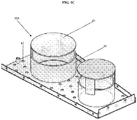
- the present invention F-Flute gas distributor's 10 ceiling 11 can be made up of rod-plate sections 29B as presented in FIG. 2A .
- the rod-plate section 29B as presented in FIG. 2A comprises staggered rods 43 that are spaced at a minimum of about 1 to about 2,54-3,81 (1 - 1/2 inches) apart and can be welded to a circumferential rim.
- the staggered rods 43 can be positioned in one or various combinations of patterns, e.g., herringbone, diagonal, etc., as presented in FIG. 2B .
- the rod-plate sections 29B allow both the gas and the slurry liquid to flow through the spacing between the rods.
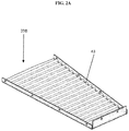
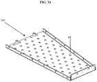
- FIG. 3A presents another alternative to the F-Flute gas distributor 10, wherein the ceiling section comprises perforated flat plate sections 29C .
- the perforated flat plate sections 29C are perforated with holes 42 .
- the perforated flat plate sections 29C can be made of sheet metal and welded to a circumferential rim.
- the holes 42 in the perforated flat plate section 29C allow both gas and slurry liquid to alternatively pass through.
- the countercurrent flow of gas and liquid alternatively through the same perforations provide quick washing effect of any coke particles formed and carried with the gas.
- the solid particles are picked up by the contacting liquid and washed downward with the flowing slurry liquid.
- the perforated flat sheet sections 29C as presented in FIG. 3B , are the simplest to construct and provide minimized liquid hold up on the top of ceiling 11 .
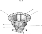
- FIG. 3B is an isometric 3D view of the F-Flute gas distributor 10 outside of the column 1 , including the ceiling 11, which comprises ceiling section 29C ( 29 A , 29B , 29D not shown in FIG 3B ), the interior cylindrical deflector wall 12 comprised of wall segments 12A connected together by conventional techniques known to those of ordinary skill in the art in an annular fashion to provide interior cylindrical deflector wall 12 .
- FIG. 3B further displays the cone shape bottom section 13 of the F-Flute gas distributor 10 .
- the interior cylindrical deflector wall 12 comprises wall segments 12A , vent windows 21 are located in several wall segments 12A around the interior cylindrical deflector wall 12.
- the segments 12A that make up the feed gas flow channel 14 are generally uniform in size, i.e., height and width and allow gas to enter the interior open area 23 .
- FIG. 4A presents yet another alternative type of F-Flute gas distributor 10 ceiling 11 containing perforated corrugated plate sections 29D.
- the perforated corrugated plate sections 29D are made of sheet metal and can be welded to a circumferential rim.
- the perforations (i.e., holes 42 ) on the corrugated plate allow both gas and slurry liquid to alternatively pass through.
- the perforated corrugated plate sections 29D corrugated sheet provides increased effective area for both the gas and liquid to pass through the roof.
- the countercurrent flow of gas and liquid alternatively through the same corrugation holes provide quick washing effect of any coke particles formed and carried with the gas.
- the presently claimed F-Flute gas distributor 10 invention can use of any combination of the afore described ceiling sections.
- FIG. 5 is a graphic representation of the superheated feed gas and slurry liquid temperature (°C) and traffic (i.e., gas and liquid flow rate in kg/hr).
- the temperatures and flow rates are measured from the F-Flute gas distributor's inlet area, i.e., the superheated feed gas at gas inlet nozzle of FIG. 1A to the packing inlet.
- the simulated traffic and temperature of both slurry liquid which enters the column 1 through slurry liquid distributor 44 of FIG. 1A ) and superheated gas stream into and out of the F-Flute gas distributor.
- the graphic representation indicates that the superheated feed gas enters the claimed F-Flute gas distributor at a temperature of approximately 560 C° and is immediately quenched to approximately 420 C° inside the F-flute gas distributor's feed gas flow channel by evaporating the slurry liquid.
- the mass flow of gas increases from approximately from about 500,000 kg/hr to a maximum of approximately 1,600,000 kg/hr, and similarly the liquid rate increases and drops to approximately 1,100,000 kg/hr from 1,550,000 kg/he to 450,000 kg/hr.
- the gas from the superheated gas feed leaves the F-Flute gas distributor (flute outlet) at a rate of approximately 1,200,000 kg/hr and a temperature of approximately 410°C.
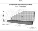
- FIG. 6 is a graphic representation of the cost ratio for revamping three different size main fractionator towers with the presently claimed F-Flute gas distribution of FIG. 1A .
- Conventional revamping of existing main fractionator towers require replacing the tower feed nozzle(s) and swaging a portion of the length of refractory line transfer line leading to the feed nozzle, of a length equivalent to 5-7 time the feed nozzle diameter, in proportional cross sectional area to the ratio of the revamp/original design capacity.
- This elaborate work can be avoided by installing the claimed F-flute gas distributor, since it provides an even distribution of the quenched superheated feed gas under the packing above the feed nozzle.
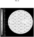
- FIGs. 7 - 11 To show the improved gas distribution of the F-Flute gas distributor of Fig. 1A , computational fluid dynamics (CFD) simulations were prepared, the results of which are presented FIGs. 7 - 11 .
- the computational fluid dynamics simulations of FIGs. 7 - 11 illustrate three dimensional gas distribution velocity magnitude contours in the cross section of a main fractionator column.
- the simulations presented in FIGs. 7 - 10 illustrate gas distribution in the cross section of a main fractionator column 5 cm below the packing entrance with and without an F-Flute gas distributor, respectively.
- the feed gas inlet nozzle is positioned on the left side of each Figure, i.e., FIGs. 7-11 .
- FIG. 7 and FIG. 8 present CFD simulation models of gas distribution velocity magnitude contours of gas distribution (i.e., gas distribution patterns) in the cross section of a main fractionator column 5 cm below the packing entrance with and without the claimed F-Flute gas distributor, respectively.
- the comparison can be measured using peak to average velocity (PAV) levels.
- PAV peak to average velocity
- the PAV levels range in numerical value from 0.00 to 8.38.
- the empty column, i.e., FIG. 7 absent the F-Flute gas distributor, has a PAV magnitude of 8.38 times the average velocity level.
- FIG. 7 displays prominent velocity magnitude contours illustrated by large oval contours with high PAV levels leaving the feed gas inlet nozzle and directed to the opposite sides of the fractionator column.
- the large oval contours are separated by a narrow velocity magnitude contour having a low PAV level.
- the pattern of the velocity magnitude contours in FIG. 7 indicate an extremely uneven velocity distribution of gas within the cross section of the column.
- the simulation of the column with the claimed F-Flute gas distributor, i.e., FIG. 8 has a PAV magnitude of 4.45 that is 47% lower than the empty column.
- the substantially even velocity magnitude contours within the cross section of the column presented in FIG. 8 are illustrated by the uniformity of the contours displayed and the absence of high PAV levels.
- FIGs. 9 and 10 are CFD simulation models of vertical gas distribution velocity magnitude contours (i.e., gas distribution patterns) at 5 cm below the packing of the column.
- FIG. 9 indicates the vertical gas distribution velocity magnitude contours for the empty column, i.e., absent the claimed F-Flute gas distributor
- FIG. 10 presents the vertical gas distribution velocity magnitude contours for the column with the claimed F-Flute gas distributor installed.
- the PAV levels range in numerical value from - 0.50 to 2.81.
- the simulation of the empty column in FIG. 9 measures a PAV vertical component at 2.8 times the average velocity level illustrated by significant oval velocity magnitude contours having high PAV levels leaving the feed gas inlet nozzle and directed to the opposite sides of the fractionator column.
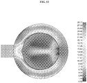
- FIG. 11 is a CFD simulation model illustrating superheated feed gas velocity magnitude contours (i.e., gas distribution patterns) inside an F-Flute gas distributor of the present claimed invention at the feed gas inlet nozzle level. This simulation clearly indicates uniform velocity magnitude contours over the majority of the feed gas flow channel and interior open area of the claimed F-Flute gas distributor.
- the F-Flute gas distributor of the invention will enhance heat and mass transfer by reducing the Sauter mean diameter (SMD) of the droplet distribution.
- SMD Sauter mean diameter
- Table 1 presents the estimated difference in SMD and heat transfer with and without the F-Flute gas distributor of FIG. 1A .
- TABLE 1 Design SMD-mm Heat Transfer - Watt/°K Empty Colum 4.0 4.2 E 05 F-Flute gas distributor 10 2.7 5.5 E 05
- the plurality of vent windows in the F-Flute gas distributor are positioned throughout the interior cylindrical deflector and the wall and chimneys positioned throughout the ceiling, allow for the cooled separated superheated feed gas to exit the distributor into the column's interior full cross section open area with greatly slowed and uniform velocity for distribution to packing or trays located within the column and above the F-Flute gas distributor.
- the walls of the F-Flute gas distributor i.e., interior cylindrical deflector wall, cone shape bottom section that extends the interior cylindrical deflector wall and the interior side of column shell wall, which comprises the exterior wall of the F-Flute gas distributor, are entirely wetted with slurry liquid.
- the interior cylindrical deflector wall, bottom section, and interior side of column shell wall are completely wetted because the ceiling is connected to the interior cylindrical deflector wall and the interior side of column shell wall through a connection device, such as, a dowel, circular rim, welded rod or bracket, and the like, to include a plurality of openings so that the slurry liquid can fall vertically down the interior cylindrical deflector wall, bottom section, and interior side of column shell wall and keep them wetted.
- the expansion of the superheated feed gas from the feed gas inlet nozzle together with the showering of the slurry liquid from the ceiling sections inside the F-Flute gas distributor provides a vehicle for the solid catalyst fines to separate out of the superheated feed gas and be carried with the large flow of slurry liquid down to the column sump without causing erosion problems to the column walls and internals. If the solid catalyst fines and coke particle are not efficiently separated from the superheated feed gas at point of entry to the column and pass with the superheated feed gas to the slurry packed section and deposit on its packing, the column's efficiency to cool the feed gas is reduced. Moreover, the column requires more frequent cleaning for the removal of the solid catalyst fines and coke particle.
- the F-Flute gas distributor of the invention has been shown to decrease significantly the maximum local gas velocity below the packing in the portion of the column situated above the F-Flute gas distributor, i.e., cooled superheated feed gas in the interior full cross section open area.
- This reduction in local gas velocity results in a more uniform distribution of gas pressure and ultimately a more efficient heat transfer in the slurry section as well as better fractionation in the upper column sections.
- An even distribution of the gas on the packing and trays is critical for proper heat and mass transfer. Even distribution can be accomplished for a higher degree of heat exchange and fractionation through the use of the F-Flute gas distributor of the present invention, which allows the conventionally designed capacity profile of a given mass and/heat transfer column/MF column to be exceeded well beyond its traditionally accepted limitations.
- the F-Flute gas distributor of the present invention would significantly decrease the maximum local velocity below a packing or tray in a column and therefore improve the velocity profile below the packing/tray.
- the invention further provides lower temperature of the gas flow to the packed slurry section as well as more even distribution, these two factors result in reduction in the required column diameter.
- the more even distribution of bottom gas to the tower sections above improve the column internals efficiency for heat and mass transfer and leads to a reduction in the overall column height.
- the novel features of the present invention have been shown to produce this uniform distribution of gas pressure at a level above any known prior art gas distributor.
- the presently claimed F-Flute gas distributor provides a low column skin temperature by cooling the feed gas first with the showering slurry liquid at entry to the column inside the F-Flute gas distributor.
- the gas distributor reduces or eliminates "jetting" of the superheated feed gas, whereby the superheated feed gas hits the column wall creating dry spots and causes the column wall to reach temperatures above the design temperature of the column shell.
- the claimed F-Flute gas distributor also avoids column shell (i.e., wall) erosion by eliminating the jetting effect of the superheated feed gas containing the erosive catalyst fines that continuously and at high velocities impinge the column wall and cause local erosion and/or thinning of the column shell in area directly opposite to the feed nozzle.
- the use of the claimed F-Flute gas distributor will remove the catalyst fines by the showering slurry liquid inside the F-Flute gas distributor and there will be no direct contact of the superheated feed gas with the column shell wall.
Applications Claiming Priority (2)
| Application Number | Priority Date | Filing Date | Title |
|---|---|---|---|
| US14/603,511 US9410750B1 (en) | 2015-01-23 | 2015-01-23 | Gas distributor for heat exchange and/or mass transfer column |
| PCT/US2016/014468 WO2016118827A1 (en) | 2015-01-23 | 2016-01-22 | Gas distributor for heat exchange and/or mass transfer column |
Publications (3)
| Publication Number | Publication Date |
|---|---|
| EP3247486A1 EP3247486A1 (en) | 2017-11-29 |
| EP3247486A4 EP3247486A4 (en) | 2018-08-29 |
| EP3247486B1 true EP3247486B1 (en) | 2019-11-06 |
Family
ID=56417791
Family Applications (1)
| Application Number | Title | Priority Date | Filing Date |
|---|---|---|---|
| EP16740820.2A Active EP3247486B1 (en) | 2015-01-23 | 2016-01-22 | Heat exchange and/or mass transfer column comprising a gas distributor and method for distributing gas |
Country Status (11)
| Country | Link |
|---|---|
| US (2) | US9410750B1 (ru) |
| EP (1) | EP3247486B1 (ru) |
| JP (1) | JP6684813B2 (ru) |
| KR (1) | KR101914250B1 (ru) |
| CN (1) | CN107249721B (ru) |
| BR (1) | BR112017015741B1 (ru) |
| CA (1) | CA2974700C (ru) |
| ES (1) | ES2767656T3 (ru) |
| MX (2) | MX2017009556A (ru) |
| RU (1) | RU2674424C1 (ru) |
| WO (1) | WO2016118827A1 (ru) |
Families Citing this family (16)
| Publication number | Priority date | Publication date | Assignee | Title |
|---|---|---|---|---|
| KR101646125B1 (ko) * | 2015-02-16 | 2016-08-12 | 현대자동차 주식회사 | 가스 포집 플랜트 |
| KR101637291B1 (ko) * | 2015-02-16 | 2016-07-07 | 현대자동차 주식회사 | 흡수반응 세퍼레이터를 구비한 흡수탑 |
| DE102015122209A1 (de) * | 2015-12-18 | 2017-02-16 | Basf Se | Kolonne zur thermischen Behandlung von fluiden Gemischen |
| CN106693432B (zh) * | 2017-03-22 | 2023-12-12 | 中国石油大学(华东) | 一种离心旋流除沫型气液混相进料分布器 |
| CN108050861A (zh) * | 2017-11-01 | 2018-05-18 | 中石化广州工程有限公司 | 一种液化天然气气液均布器 |
| CN108201705A (zh) * | 2018-03-21 | 2018-06-26 | 青岛科技大学 | 一种刮膜式短程蒸馏初始进料装置 |
| CN108800988B (zh) * | 2018-05-28 | 2023-09-08 | 广东东实开能能源有限公司 | 一种直燃式烟气加热装置 |
| US11643601B2 (en) * | 2018-06-29 | 2023-05-09 | Renuva, Inc. | Horizontal rotating drum retort, distillation column, and distillation system |
| CN108939595B (zh) * | 2018-07-18 | 2024-02-27 | 嘉兴学院 | 多路径扩散的气体分布装置 |
| JP7269739B2 (ja) * | 2019-01-17 | 2023-05-09 | イエフペ エネルジ ヌヴェル | 触媒反応器の着脱式バスケット |
| US11266923B2 (en) | 2019-04-24 | 2022-03-08 | Technip Process Technology, Inc. | Fluid distribution devices |
| US11198823B2 (en) * | 2019-07-24 | 2021-12-14 | Baker Hughes Holdings Llc | Advanced process fluid cooling systems and related methods |
| KR20220045372A (ko) * | 2020-10-05 | 2022-04-12 | 주식회사 엘지화학 | 스트리핑 장치 및 스트리핑 방법 |
| CN112892415B (zh) * | 2021-01-28 | 2022-12-27 | 中国工程物理研究院核物理与化学研究所 | 适用于小型气液传质填料塔的高效花瓣式液体再分布器 |
| US20230008997A1 (en) * | 2021-07-07 | 2023-01-12 | Arya Ayaskanta | System and method for super-heat removal in packed distillation column |
| CN116236978B (zh) * | 2023-02-01 | 2023-09-22 | 北京石油化工学院 | 一种气体分布器及包含其的气-固反应器 |
Family Cites Families (35)
| Publication number | Priority date | Publication date | Assignee | Title |
|---|---|---|---|---|
| US2591343A (en) * | 1949-08-10 | 1952-04-01 | Gulf Oil Corp | Tray for fractionating equipment |
| US3175340A (en) * | 1959-11-16 | 1965-03-30 | Hertha M Schulze | Method and apparatus for gas scrubbing |
| US3348364A (en) | 1965-10-23 | 1967-10-24 | Nat Dust Collector Corp | Gas scrubber with improved liquid separator |
| US3687630A (en) * | 1968-07-24 | 1972-08-29 | John P Tailor | Gas cleaning process |
| USRE28616E (en) * | 1969-04-04 | 1975-11-18 | Mass contact between media of different densities | |
| US3651619A (en) | 1970-03-30 | 1972-03-28 | Mitsugi Miura | Apparatus for purification of gas |
| US3917458A (en) | 1972-07-21 | 1975-11-04 | Nicoll Jr Frank S | Gas filtration system employing a filtration screen of particulate solids |
| US3916021A (en) | 1973-03-21 | 1975-10-28 | James D Hajek | Liquid redistributor for a fractionating column |
| US3925039A (en) * | 1974-11-18 | 1975-12-09 | Us Energy | System for treating flue gas |
| US4351803A (en) | 1980-03-10 | 1982-09-28 | Phillips Petroleum Company | Hydrocarbon heating apparatus |
| NL8100955A (nl) | 1981-02-27 | 1982-09-16 | Pielkenrood Vinitex Bv | Meerfasenafscheider. |
| DK154038C (da) * | 1984-02-28 | 1989-02-13 | Anhydro As | Gasfordelingsanordning til tilfoersel af en behandlingsgas til et forstoevningskammer |
| US4571311A (en) * | 1985-01-22 | 1986-02-18 | Combustion Engineering, Inc. | Apparatus for introducing a process gas into a treatment chamber |
| US5106544A (en) | 1990-01-31 | 1992-04-21 | Glitsch, Inc. | Method of and apparatus for vapor distribution |
| US5632933A (en) | 1993-08-04 | 1997-05-27 | Koch Engineering Company, Inc. | Method and apparatus using guide vanes for vapor distribution in mass transfer and heat exchange columns |
| US5605654A (en) | 1993-08-04 | 1997-02-25 | Koch Engineering Company, Inc. | Method and apparatus to improve vapor distribution in mass transfer and heat exchange columns |
| US5558818A (en) | 1995-02-14 | 1996-09-24 | The Babcock & Wilcox Company | Wet flue gas scrubber having an evenly distributed flue gas inlet |
| JP4515569B2 (ja) | 1998-12-15 | 2010-08-04 | ズルツァー・ケムテック・アクチェンゲゼルシャフト | 流体を装置へ供給する方法及び同方法を実施可能なカラム |
| US6309553B1 (en) | 1999-09-28 | 2001-10-30 | Biothane Corporation | Phase separator having multiple separation units, upflow reactor apparatus, and methods for phase separation |
| FR2827791B1 (fr) | 2001-07-26 | 2003-10-31 | Total Raffinage Distribution | Procede et dispositif d'introduction d'un melange liquide-vapeur dans une colonne de distillation cylindrique a alimentation radiale |
| DE60314502T2 (de) | 2002-04-03 | 2007-10-31 | Koch-Glitsch, LP, Wichita | Verfahren und vorrichtung zum erleichtern einer gleichmässigeren dampfverteilung in stoff- und wärmeaustauschkolonnen |
| EP1542790B1 (en) | 2002-05-28 | 2012-07-18 | Fluor Corporation | Methods and apparatus for mixing and distributing fluids |
| US6889962B2 (en) | 2003-08-06 | 2005-05-10 | Koch-Glitsch, Lp | Fluid stream feed device for mass transfer column |
| US6948705B2 (en) | 2003-10-07 | 2005-09-27 | Amt International, Inc. | Gas/liquid contacting apparatus |
| US7104529B2 (en) | 2003-11-17 | 2006-09-12 | Koch-Glitsch, Lp | Method and apparatus for facilitating more uniform vapor distribution in mass transfer and heat exchange columns |
| NO320351B1 (no) | 2004-03-05 | 2005-11-28 | Bjorn Christiansen | Skovldiffusor |
| RU2397001C2 (ru) | 2005-05-19 | 2010-08-20 | Шелл Интернэшнл Рисерч Маатсхаппий Б.В. | Входное устройство для текучей среды, его использование и способ модернизации |
| CN101479029A (zh) * | 2006-05-01 | 2009-07-08 | 斯通及维布斯特工艺技术有限公司 | 三相蒸汽分配器 |
| US7744067B2 (en) | 2006-05-01 | 2010-06-29 | Stone & Webster Process Technology, Inc. | Three phase vapor distributor |
| US7445198B2 (en) * | 2006-08-30 | 2008-11-04 | Uop Llc | Apparatus and process for distributing liquid |
| DE102007019816A1 (de) * | 2007-04-26 | 2008-10-30 | Linde Ag | Sammler-Verteiler-Kombination |
| US8286952B2 (en) | 2009-04-29 | 2012-10-16 | Amt International, Inc. | Vapor distributor for gas-liquid contacting columns |
| PL2380645T3 (pl) * | 2010-04-23 | 2014-11-28 | Neste Oil Oyj | Urządzenie do dystrybucji surowca dla kolumny separacyjnej |
| RU2441698C1 (ru) * | 2010-07-21 | 2012-02-10 | Открытое Акционерное Общество "Научно-Исследовательский И Проектный Институт Карбамида И Продуктов Органического Синтеза" (Оао Ниик) | Газожидкостный реактор (варианты) |
| US9914090B2 (en) | 2013-06-28 | 2018-03-13 | Uop Llc | Vapor-liquid contacting apparatuses and methods for removing contaminants from gas streams |
-
2015
- 2015-01-23 US US14/603,511 patent/US9410750B1/en active Active
-
2016
- 2016-01-22 KR KR1020177022818A patent/KR101914250B1/ko active IP Right Grant
- 2016-01-22 ES ES16740820T patent/ES2767656T3/es active Active
- 2016-01-22 CA CA2974700A patent/CA2974700C/en active Active
- 2016-01-22 JP JP2017539227A patent/JP6684813B2/ja active Active
- 2016-01-22 CN CN201680011795.3A patent/CN107249721B/zh active Active
- 2016-01-22 WO PCT/US2016/014468 patent/WO2016118827A1/en active Application Filing
- 2016-01-22 EP EP16740820.2A patent/EP3247486B1/en active Active
- 2016-01-22 BR BR112017015741-1A patent/BR112017015741B1/pt active IP Right Grant
- 2016-01-22 RU RU2017128294A patent/RU2674424C1/ru active
- 2016-01-22 MX MX2017009556A patent/MX2017009556A/es unknown
- 2016-07-06 US US15/202,849 patent/US9677830B2/en active Active
-
2017
- 2017-07-21 MX MX2023007236A patent/MX2023007236A/es unknown
Non-Patent Citations (1)
| Title |
|---|
| None * |
Also Published As
| Publication number | Publication date |
|---|---|
| EP3247486A1 (en) | 2017-11-29 |
| CA2974700A1 (en) | 2016-07-28 |
| KR101914250B1 (ko) | 2018-11-01 |
| CN107249721A (zh) | 2017-10-13 |
| US20160216051A1 (en) | 2016-07-28 |
| CA2974700C (en) | 2020-01-28 |
| US20160313077A1 (en) | 2016-10-27 |
| ES2767656T3 (es) | 2020-06-18 |
| US9410750B1 (en) | 2016-08-09 |
| JP2018502715A (ja) | 2018-02-01 |
| BR112017015741B1 (pt) | 2022-12-27 |
| BR112017015741A2 (pt) | 2018-03-13 |
| MX2017009556A (es) | 2018-06-07 |
| JP6684813B2 (ja) | 2020-04-22 |
| RU2674424C1 (ru) | 2018-12-07 |
| MX2023007236A (es) | 2023-06-29 |
| CN107249721B (zh) | 2021-07-23 |
| EP3247486A4 (en) | 2018-08-29 |
| US9677830B2 (en) | 2017-06-13 |
| WO2016118827A1 (en) | 2016-07-28 |
| KR20170110095A (ko) | 2017-10-10 |
Similar Documents
| Publication | Publication Date | Title |
|---|---|---|
| EP3247486B1 (en) | Heat exchange and/or mass transfer column comprising a gas distributor and method for distributing gas | |
| US7601310B2 (en) | Distributor system for downflow reactors | |
| US7427381B2 (en) | Vapor/liquid separation apparatus for use in cracking hydrocarbon feedstock containing resid | |
| EP1761615B1 (en) | METHOD for CRACKING A HYDROCARBON FEEDSTOCK CONTAINING RESID AND CRACKING APPARATUS THEREFOR | |
| US6338828B1 (en) | Reactor distribution apparatus and quench zone mixing apparatus | |
| US20040028579A1 (en) | Multiple bed downflow reactor | |
| KR101430272B1 (ko) | 3상 증기 분배기 | |
| RU2726531C1 (ru) | Контактная тарелка, содержащая перегораживающие барьеры для течения жидкости, и способ ее действия | |
| US10786751B2 (en) | Coker fractionator spray wash chamber | |
| EP3856382B1 (en) | A perforated-tray column and a method of revamping the same | |
| RU2798834C2 (ru) | Колонна с ситчатыми тарелками и способ ее модернизации | |
| MXPA06005333A (es) | Sistema distribuidor mejorado para factores de flujo descendente |
Legal Events
| Date | Code | Title | Description |
|---|---|---|---|
| STAA | Information on the status of an ep patent application or granted ep patent |
Free format text: STATUS: THE INTERNATIONAL PUBLICATION HAS BEEN MADE |
|
| PUAI | Public reference made under article 153(3) epc to a published international application that has entered the european phase |
Free format text: ORIGINAL CODE: 0009012 |
|
| STAA | Information on the status of an ep patent application or granted ep patent |
Free format text: STATUS: REQUEST FOR EXAMINATION WAS MADE |
|
| 17P | Request for examination filed |
Effective date: 20170821 |
|
| AK | Designated contracting states |
Kind code of ref document: A1 Designated state(s): AL AT BE BG CH CY CZ DE DK EE ES FI FR GB GR HR HU IE IS IT LI LT LU LV MC MK MT NL NO PL PT RO RS SE SI SK SM TR |
|
| AX | Request for extension of the european patent |
Extension state: BA ME |
|
| DAV | Request for validation of the european patent (deleted) | ||
| DAX | Request for extension of the european patent (deleted) | ||
| A4 | Supplementary search report drawn up and despatched |
Effective date: 20180731 |
|
| RIC1 | Information provided on ipc code assigned before grant |
Ipc: B01F 3/04 20060101AFI20180725BHEP Ipc: B01D 3/00 20060101ALI20180725BHEP Ipc: B01D 3/32 20060101ALI20180725BHEP Ipc: F28F 25/10 20060101ALI20180725BHEP Ipc: B01D 3/18 20060101ALI20180725BHEP Ipc: C10G 11/18 20060101ALI20180725BHEP |
|
| GRAP | Despatch of communication of intention to grant a patent |
Free format text: ORIGINAL CODE: EPIDOSNIGR1 |
|
| STAA | Information on the status of an ep patent application or granted ep patent |
Free format text: STATUS: GRANT OF PATENT IS INTENDED |
|
| INTG | Intention to grant announced |
Effective date: 20190502 |
|
| GRAJ | Information related to disapproval of communication of intention to grant by the applicant or resumption of examination proceedings by the epo deleted |
Free format text: ORIGINAL CODE: EPIDOSDIGR1 |
|
| STAA | Information on the status of an ep patent application or granted ep patent |
Free format text: STATUS: REQUEST FOR EXAMINATION WAS MADE |
|
| GRAR | Information related to intention to grant a patent recorded |
Free format text: ORIGINAL CODE: EPIDOSNIGR71 |
|
| GRAS | Grant fee paid |
Free format text: ORIGINAL CODE: EPIDOSNIGR3 |
|
| STAA | Information on the status of an ep patent application or granted ep patent |
Free format text: STATUS: GRANT OF PATENT IS INTENDED |
|
| GRAA | (expected) grant |
Free format text: ORIGINAL CODE: 0009210 |
|
| STAA | Information on the status of an ep patent application or granted ep patent |
Free format text: STATUS: THE PATENT HAS BEEN GRANTED |
|
| INTC | Intention to grant announced (deleted) | ||
| INTG | Intention to grant announced |
Effective date: 20190926 |
|
| AK | Designated contracting states |
Kind code of ref document: B1 Designated state(s): AL AT BE BG CH CY CZ DE DK EE ES FI FR GB GR HR HU IE IS IT LI LT LU LV MC MK MT NL NO PL PT RO RS SE SI SK SM TR |
|
| REG | Reference to a national code |
Ref country code: GB Ref legal event code: FG4D |
|
| REG | Reference to a national code |
Ref country code: CH Ref legal event code: EP Ref country code: AT Ref legal event code: REF Ref document number: 1198006 Country of ref document: AT Kind code of ref document: T Effective date: 20191115 |
|
| REG | Reference to a national code |
Ref country code: DE Ref legal event code: R096 Ref document number: 602016023805 Country of ref document: DE |
|
| REG | Reference to a national code |
Ref country code: IE Ref legal event code: FG4D |
|
| REG | Reference to a national code |
Ref country code: NL Ref legal event code: FP |
|
| REG | Reference to a national code |
Ref country code: LT Ref legal event code: MG4D |
|
| PG25 | Lapsed in a contracting state [announced via postgrant information from national office to epo] |
Ref country code: PT Free format text: LAPSE BECAUSE OF FAILURE TO SUBMIT A TRANSLATION OF THE DESCRIPTION OR TO PAY THE FEE WITHIN THE PRESCRIBED TIME-LIMIT Effective date: 20200306 Ref country code: LV Free format text: LAPSE BECAUSE OF FAILURE TO SUBMIT A TRANSLATION OF THE DESCRIPTION OR TO PAY THE FEE WITHIN THE PRESCRIBED TIME-LIMIT Effective date: 20191106 Ref country code: SE Free format text: LAPSE BECAUSE OF FAILURE TO SUBMIT A TRANSLATION OF THE DESCRIPTION OR TO PAY THE FEE WITHIN THE PRESCRIBED TIME-LIMIT Effective date: 20191106 Ref country code: FI Free format text: LAPSE BECAUSE OF FAILURE TO SUBMIT A TRANSLATION OF THE DESCRIPTION OR TO PAY THE FEE WITHIN THE PRESCRIBED TIME-LIMIT Effective date: 20191106 Ref country code: GR Free format text: LAPSE BECAUSE OF FAILURE TO SUBMIT A TRANSLATION OF THE DESCRIPTION OR TO PAY THE FEE WITHIN THE PRESCRIBED TIME-LIMIT Effective date: 20200207 Ref country code: LT Free format text: LAPSE BECAUSE OF FAILURE TO SUBMIT A TRANSLATION OF THE DESCRIPTION OR TO PAY THE FEE WITHIN THE PRESCRIBED TIME-LIMIT Effective date: 20191106 Ref country code: BG Free format text: LAPSE BECAUSE OF FAILURE TO SUBMIT A TRANSLATION OF THE DESCRIPTION OR TO PAY THE FEE WITHIN THE PRESCRIBED TIME-LIMIT Effective date: 20200206 Ref country code: NO Free format text: LAPSE BECAUSE OF FAILURE TO SUBMIT A TRANSLATION OF THE DESCRIPTION OR TO PAY THE FEE WITHIN THE PRESCRIBED TIME-LIMIT Effective date: 20200206 Ref country code: PL Free format text: LAPSE BECAUSE OF FAILURE TO SUBMIT A TRANSLATION OF THE DESCRIPTION OR TO PAY THE FEE WITHIN THE PRESCRIBED TIME-LIMIT Effective date: 20191106 |
|
| PG25 | Lapsed in a contracting state [announced via postgrant information from national office to epo] |
Ref country code: IS Free format text: LAPSE BECAUSE OF FAILURE TO SUBMIT A TRANSLATION OF THE DESCRIPTION OR TO PAY THE FEE WITHIN THE PRESCRIBED TIME-LIMIT Effective date: 20200306 Ref country code: HR Free format text: LAPSE BECAUSE OF FAILURE TO SUBMIT A TRANSLATION OF THE DESCRIPTION OR TO PAY THE FEE WITHIN THE PRESCRIBED TIME-LIMIT Effective date: 20191106 Ref country code: RS Free format text: LAPSE BECAUSE OF FAILURE TO SUBMIT A TRANSLATION OF THE DESCRIPTION OR TO PAY THE FEE WITHIN THE PRESCRIBED TIME-LIMIT Effective date: 20191106 |
|
| REG | Reference to a national code |
Ref country code: ES Ref legal event code: FG2A Ref document number: 2767656 Country of ref document: ES Kind code of ref document: T3 Effective date: 20200618 |
|
| PG25 | Lapsed in a contracting state [announced via postgrant information from national office to epo] |
Ref country code: AL Free format text: LAPSE BECAUSE OF FAILURE TO SUBMIT A TRANSLATION OF THE DESCRIPTION OR TO PAY THE FEE WITHIN THE PRESCRIBED TIME-LIMIT Effective date: 20191106 |
|
| PG25 | Lapsed in a contracting state [announced via postgrant information from national office to epo] |
Ref country code: EE Free format text: LAPSE BECAUSE OF FAILURE TO SUBMIT A TRANSLATION OF THE DESCRIPTION OR TO PAY THE FEE WITHIN THE PRESCRIBED TIME-LIMIT Effective date: 20191106 Ref country code: CZ Free format text: LAPSE BECAUSE OF FAILURE TO SUBMIT A TRANSLATION OF THE DESCRIPTION OR TO PAY THE FEE WITHIN THE PRESCRIBED TIME-LIMIT Effective date: 20191106 Ref country code: RO Free format text: LAPSE BECAUSE OF FAILURE TO SUBMIT A TRANSLATION OF THE DESCRIPTION OR TO PAY THE FEE WITHIN THE PRESCRIBED TIME-LIMIT Effective date: 20191106 Ref country code: DK Free format text: LAPSE BECAUSE OF FAILURE TO SUBMIT A TRANSLATION OF THE DESCRIPTION OR TO PAY THE FEE WITHIN THE PRESCRIBED TIME-LIMIT Effective date: 20191106 |
|
| REG | Reference to a national code |
Ref country code: DE Ref legal event code: R097 Ref document number: 602016023805 Country of ref document: DE |
|
| REG | Reference to a national code |
Ref country code: AT Ref legal event code: MK05 Ref document number: 1198006 Country of ref document: AT Kind code of ref document: T Effective date: 20191106 |
|
| PG25 | Lapsed in a contracting state [announced via postgrant information from national office to epo] |
Ref country code: SM Free format text: LAPSE BECAUSE OF FAILURE TO SUBMIT A TRANSLATION OF THE DESCRIPTION OR TO PAY THE FEE WITHIN THE PRESCRIBED TIME-LIMIT Effective date: 20191106 Ref country code: MC Free format text: LAPSE BECAUSE OF FAILURE TO SUBMIT A TRANSLATION OF THE DESCRIPTION OR TO PAY THE FEE WITHIN THE PRESCRIBED TIME-LIMIT Effective date: 20191106 Ref country code: SK Free format text: LAPSE BECAUSE OF FAILURE TO SUBMIT A TRANSLATION OF THE DESCRIPTION OR TO PAY THE FEE WITHIN THE PRESCRIBED TIME-LIMIT Effective date: 20191106 |
|
| REG | Reference to a national code |
Ref country code: CH Ref legal event code: PL |
|
| PLBE | No opposition filed within time limit |
Free format text: ORIGINAL CODE: 0009261 |
|
| STAA | Information on the status of an ep patent application or granted ep patent |
Free format text: STATUS: NO OPPOSITION FILED WITHIN TIME LIMIT |
|
| 26N | No opposition filed |
Effective date: 20200807 |
|
| PG25 | Lapsed in a contracting state [announced via postgrant information from national office to epo] |
Ref country code: LU Free format text: LAPSE BECAUSE OF NON-PAYMENT OF DUE FEES Effective date: 20200122 |
|
| PG25 | Lapsed in a contracting state [announced via postgrant information from national office to epo] |
Ref country code: LI Free format text: LAPSE BECAUSE OF NON-PAYMENT OF DUE FEES Effective date: 20200131 Ref country code: SI Free format text: LAPSE BECAUSE OF FAILURE TO SUBMIT A TRANSLATION OF THE DESCRIPTION OR TO PAY THE FEE WITHIN THE PRESCRIBED TIME-LIMIT Effective date: 20191106 Ref country code: AT Free format text: LAPSE BECAUSE OF FAILURE TO SUBMIT A TRANSLATION OF THE DESCRIPTION OR TO PAY THE FEE WITHIN THE PRESCRIBED TIME-LIMIT Effective date: 20191106 Ref country code: CH Free format text: LAPSE BECAUSE OF NON-PAYMENT OF DUE FEES Effective date: 20200131 |
|
| PG25 | Lapsed in a contracting state [announced via postgrant information from national office to epo] |
Ref country code: IE Free format text: LAPSE BECAUSE OF NON-PAYMENT OF DUE FEES Effective date: 20200122 |
|
| REG | Reference to a national code |
Ref country code: DE Ref legal event code: R079 Ref document number: 602016023805 Country of ref document: DE Free format text: PREVIOUS MAIN CLASS: B01F0003040000 Ipc: B01F0023200000 |
|
| PG25 | Lapsed in a contracting state [announced via postgrant information from national office to epo] |
Ref country code: TR Free format text: LAPSE BECAUSE OF FAILURE TO SUBMIT A TRANSLATION OF THE DESCRIPTION OR TO PAY THE FEE WITHIN THE PRESCRIBED TIME-LIMIT Effective date: 20191106 Ref country code: MT Free format text: LAPSE BECAUSE OF FAILURE TO SUBMIT A TRANSLATION OF THE DESCRIPTION OR TO PAY THE FEE WITHIN THE PRESCRIBED TIME-LIMIT Effective date: 20191106 Ref country code: CY Free format text: LAPSE BECAUSE OF FAILURE TO SUBMIT A TRANSLATION OF THE DESCRIPTION OR TO PAY THE FEE WITHIN THE PRESCRIBED TIME-LIMIT Effective date: 20191106 |
|
| PG25 | Lapsed in a contracting state [announced via postgrant information from national office to epo] |
Ref country code: MK Free format text: LAPSE BECAUSE OF FAILURE TO SUBMIT A TRANSLATION OF THE DESCRIPTION OR TO PAY THE FEE WITHIN THE PRESCRIBED TIME-LIMIT Effective date: 20191106 |
|
| PGFP | Annual fee paid to national office [announced via postgrant information from national office to epo] |
Ref country code: ES Payment date: 20230216 Year of fee payment: 8 |
|
| PGFP | Annual fee paid to national office [announced via postgrant information from national office to epo] |
Ref country code: IT Payment date: 20221229 Year of fee payment: 8 |
|
| P01 | Opt-out of the competence of the unified patent court (upc) registered |
Effective date: 20230601 |
|
| PGFP | Annual fee paid to national office [announced via postgrant information from national office to epo] |
Ref country code: GB Payment date: 20231221 Year of fee payment: 9 |
|
| PGFP | Annual fee paid to national office [announced via postgrant information from national office to epo] |
Ref country code: NL Payment date: 20231226 Year of fee payment: 9 Ref country code: FR Payment date: 20231222 Year of fee payment: 9 |
|
| PGFP | Annual fee paid to national office [announced via postgrant information from national office to epo] |
Ref country code: BE Payment date: 20231227 Year of fee payment: 9 |
|
| PGFP | Annual fee paid to national office [announced via postgrant information from national office to epo] |
Ref country code: ES Payment date: 20240208 Year of fee payment: 9 |
|
| PGFP | Annual fee paid to national office [announced via postgrant information from national office to epo] |
Ref country code: DE Payment date: 20231220 Year of fee payment: 9 |