EP3247259B1 - Visualisierung einer vorrichtung durch optische formmessung eines führungsdrahtes - Google Patents
Visualisierung einer vorrichtung durch optische formmessung eines führungsdrahtes Download PDFInfo
- Publication number
- EP3247259B1 EP3247259B1 EP15825970.5A EP15825970A EP3247259B1 EP 3247259 B1 EP3247259 B1 EP 3247259B1 EP 15825970 A EP15825970 A EP 15825970A EP 3247259 B1 EP3247259 B1 EP 3247259B1
- Authority
- EP
- European Patent Office
- Prior art keywords
- guidewire
- deployment system
- endograft
- oss
- deployment
- Prior art date
- Legal status (The legal status is an assumption and is not a legal conclusion. Google has not performed a legal analysis and makes no representation as to the accuracy of the status listed.)
- Active
Links
- 230000003287 optical effect Effects 0.000 title claims description 38
- 238000012800 visualization Methods 0.000 title description 9
- 230000007246 mechanism Effects 0.000 claims description 15
- 230000008878 coupling Effects 0.000 claims description 13
- 238000010168 coupling process Methods 0.000 claims description 13
- 238000005859 coupling reaction Methods 0.000 claims description 13
- 239000013307 optical fiber Substances 0.000 claims description 11
- 239000000853 adhesive Substances 0.000 claims description 8
- 230000001070 adhesive effect Effects 0.000 claims description 8
- 230000033001 locomotion Effects 0.000 claims description 6
- 238000005259 measurement Methods 0.000 claims description 4
- 238000000034 method Methods 0.000 description 35
- 239000000835 fiber Substances 0.000 description 33
- 238000003384 imaging method Methods 0.000 description 10
- 238000010586 diagram Methods 0.000 description 9
- 206010002329 Aneurysm Diseases 0.000 description 8
- 238000002594 fluoroscopy Methods 0.000 description 8
- 230000006870 function Effects 0.000 description 8
- 210000004204 blood vessel Anatomy 0.000 description 7
- 239000003550 marker Substances 0.000 description 6
- 230000008569 process Effects 0.000 description 6
- 230000008439 repair process Effects 0.000 description 6
- 238000002591 computed tomography Methods 0.000 description 5
- 238000013461 design Methods 0.000 description 5
- 238000012986 modification Methods 0.000 description 5
- 230000004048 modification Effects 0.000 description 5
- 210000005166 vasculature Anatomy 0.000 description 5
- 210000003484 anatomy Anatomy 0.000 description 4
- 208000001750 Endoleak Diseases 0.000 description 2
- 208000002223 abdominal aortic aneurysm Diseases 0.000 description 2
- 210000001367 artery Anatomy 0.000 description 2
- 230000008901 benefit Effects 0.000 description 2
- 230000000694 effects Effects 0.000 description 2
- 239000007943 implant Substances 0.000 description 2
- 238000013152 interventional procedure Methods 0.000 description 2
- 210000005248 left atrial appendage Anatomy 0.000 description 2
- 230000013011 mating Effects 0.000 description 2
- 210000000056 organ Anatomy 0.000 description 2
- 230000005855 radiation Effects 0.000 description 2
- 210000002254 renal artery Anatomy 0.000 description 2
- 238000007789 sealing Methods 0.000 description 2
- 239000004065 semiconductor Substances 0.000 description 2
- 238000002560 therapeutic procedure Methods 0.000 description 2
- 230000000007 visual effect Effects 0.000 description 2
- 0 *C1CC(CCCCCC2C[C@@]3(CC=CCC3)C(*)=CCC2)CCC1 Chemical compound *C1CC(CCCCCC2C[C@@]3(CC=CCC3)C(*)=CCC2)CCC1 0.000 description 1
- 208000009304 Acute Kidney Injury Diseases 0.000 description 1
- 208000033626 Renal failure acute Diseases 0.000 description 1
- 201000011040 acute kidney failure Diseases 0.000 description 1
- 208000012998 acute renal failure Diseases 0.000 description 1
- 238000004873 anchoring Methods 0.000 description 1
- 210000000709 aorta Anatomy 0.000 description 1
- 238000013459 approach Methods 0.000 description 1
- 230000005540 biological transmission Effects 0.000 description 1
- 239000008280 blood Substances 0.000 description 1
- 210000004369 blood Anatomy 0.000 description 1
- 230000017531 blood circulation Effects 0.000 description 1
- 230000000112 colonic effect Effects 0.000 description 1
- 238000004891 communication Methods 0.000 description 1
- 238000004590 computer program Methods 0.000 description 1
- 238000010276 construction Methods 0.000 description 1
- 239000000994 contrast dye Substances 0.000 description 1
- 239000002872 contrast media Substances 0.000 description 1
- 229940039231 contrast media Drugs 0.000 description 1
- 230000001066 destructive effect Effects 0.000 description 1
- 238000005516 engineering process Methods 0.000 description 1
- 125000001153 fluoro group Chemical group F* 0.000 description 1
- 210000001035 gastrointestinal tract Anatomy 0.000 description 1
- 238000003780 insertion Methods 0.000 description 1
- 230000037431 insertion Effects 0.000 description 1
- 230000010354 integration Effects 0.000 description 1
- 230000003993 interaction Effects 0.000 description 1
- 208000028867 ischemia Diseases 0.000 description 1
- 208000017169 kidney disease Diseases 0.000 description 1
- 230000004807 localization Effects 0.000 description 1
- 210000004072 lung Anatomy 0.000 description 1
- 210000004115 mitral valve Anatomy 0.000 description 1
- 230000000737 periodic effect Effects 0.000 description 1
- 230000002093 peripheral effect Effects 0.000 description 1
- 238000000053 physical method Methods 0.000 description 1
- 238000012545 processing Methods 0.000 description 1
- 239000002096 quantum dot Substances 0.000 description 1
- 238000009877 rendering Methods 0.000 description 1
- 238000000926 separation method Methods 0.000 description 1
- 239000007787 solid Substances 0.000 description 1
- 230000000087 stabilizing effect Effects 0.000 description 1
- 238000011477 surgical intervention Methods 0.000 description 1
- 238000001356 surgical procedure Methods 0.000 description 1
- 210000000115 thoracic cavity Anatomy 0.000 description 1
- 230000009466 transformation Effects 0.000 description 1
- 238000013519 translation Methods 0.000 description 1
Images


Classifications
-
- A—HUMAN NECESSITIES
- A61—MEDICAL OR VETERINARY SCIENCE; HYGIENE
- A61B—DIAGNOSIS; SURGERY; IDENTIFICATION
- A61B34/00—Computer-aided surgery; Manipulators or robots specially adapted for use in surgery
- A61B34/20—Surgical navigation systems; Devices for tracking or guiding surgical instruments, e.g. for frameless stereotaxis
-
- A—HUMAN NECESSITIES
- A61—MEDICAL OR VETERINARY SCIENCE; HYGIENE
- A61F—FILTERS IMPLANTABLE INTO BLOOD VESSELS; PROSTHESES; DEVICES PROVIDING PATENCY TO, OR PREVENTING COLLAPSING OF, TUBULAR STRUCTURES OF THE BODY, e.g. STENTS; ORTHOPAEDIC, NURSING OR CONTRACEPTIVE DEVICES; FOMENTATION; TREATMENT OR PROTECTION OF EYES OR EARS; BANDAGES, DRESSINGS OR ABSORBENT PADS; FIRST-AID KITS
- A61F2/00—Filters implantable into blood vessels; Prostheses, i.e. artificial substitutes or replacements for parts of the body; Appliances for connecting them with the body; Devices providing patency to, or preventing collapsing of, tubular structures of the body, e.g. stents
- A61F2/02—Prostheses implantable into the body
- A61F2/04—Hollow or tubular parts of organs, e.g. bladders, tracheae, bronchi or bile ducts
- A61F2/06—Blood vessels
- A61F2/07—Stent-grafts
-
- A—HUMAN NECESSITIES
- A61—MEDICAL OR VETERINARY SCIENCE; HYGIENE
- A61B—DIAGNOSIS; SURGERY; IDENTIFICATION
- A61B5/00—Measuring for diagnostic purposes; Identification of persons
- A61B5/0059—Measuring for diagnostic purposes; Identification of persons using light, e.g. diagnosis by transillumination, diascopy, fluorescence
- A61B5/0082—Measuring for diagnostic purposes; Identification of persons using light, e.g. diagnosis by transillumination, diascopy, fluorescence adapted for particular medical purposes
- A61B5/0084—Measuring for diagnostic purposes; Identification of persons using light, e.g. diagnosis by transillumination, diascopy, fluorescence adapted for particular medical purposes for introduction into the body, e.g. by catheters
-
- A—HUMAN NECESSITIES
- A61—MEDICAL OR VETERINARY SCIENCE; HYGIENE
- A61B—DIAGNOSIS; SURGERY; IDENTIFICATION
- A61B5/00—Measuring for diagnostic purposes; Identification of persons
- A61B5/103—Detecting, measuring or recording devices for testing the shape, pattern, colour, size or movement of the body or parts thereof, for diagnostic purposes
- A61B5/107—Measuring physical dimensions, e.g. size of the entire body or parts thereof
- A61B5/1076—Measuring physical dimensions, e.g. size of the entire body or parts thereof for measuring dimensions inside body cavities, e.g. using catheters
-
- A—HUMAN NECESSITIES
- A61—MEDICAL OR VETERINARY SCIENCE; HYGIENE
- A61B—DIAGNOSIS; SURGERY; IDENTIFICATION
- A61B5/00—Measuring for diagnostic purposes; Identification of persons
- A61B5/68—Arrangements of detecting, measuring or recording means, e.g. sensors, in relation to patient
- A61B5/6846—Arrangements of detecting, measuring or recording means, e.g. sensors, in relation to patient specially adapted to be brought in contact with an internal body part, i.e. invasive
- A61B5/6847—Arrangements of detecting, measuring or recording means, e.g. sensors, in relation to patient specially adapted to be brought in contact with an internal body part, i.e. invasive mounted on an invasive device
- A61B5/6851—Guide wires
-
- A—HUMAN NECESSITIES
- A61—MEDICAL OR VETERINARY SCIENCE; HYGIENE
- A61B—DIAGNOSIS; SURGERY; IDENTIFICATION
- A61B5/00—Measuring for diagnostic purposes; Identification of persons
- A61B5/68—Arrangements of detecting, measuring or recording means, e.g. sensors, in relation to patient
- A61B5/6846—Arrangements of detecting, measuring or recording means, e.g. sensors, in relation to patient specially adapted to be brought in contact with an internal body part, i.e. invasive
- A61B5/6867—Arrangements of detecting, measuring or recording means, e.g. sensors, in relation to patient specially adapted to be brought in contact with an internal body part, i.e. invasive specially adapted to be attached or implanted in a specific body part
- A61B5/6876—Blood vessel
-
- A—HUMAN NECESSITIES
- A61—MEDICAL OR VETERINARY SCIENCE; HYGIENE
- A61B—DIAGNOSIS; SURGERY; IDENTIFICATION
- A61B90/00—Instruments, implements or accessories specially adapted for surgery or diagnosis and not covered by any of the groups A61B1/00 - A61B50/00, e.g. for luxation treatment or for protecting wound edges
- A61B90/39—Markers, e.g. radio-opaque or breast lesions markers
-
- A—HUMAN NECESSITIES
- A61—MEDICAL OR VETERINARY SCIENCE; HYGIENE
- A61F—FILTERS IMPLANTABLE INTO BLOOD VESSELS; PROSTHESES; DEVICES PROVIDING PATENCY TO, OR PREVENTING COLLAPSING OF, TUBULAR STRUCTURES OF THE BODY, e.g. STENTS; ORTHOPAEDIC, NURSING OR CONTRACEPTIVE DEVICES; FOMENTATION; TREATMENT OR PROTECTION OF EYES OR EARS; BANDAGES, DRESSINGS OR ABSORBENT PADS; FIRST-AID KITS
- A61F2/00—Filters implantable into blood vessels; Prostheses, i.e. artificial substitutes or replacements for parts of the body; Appliances for connecting them with the body; Devices providing patency to, or preventing collapsing of, tubular structures of the body, e.g. stents
- A61F2/95—Instruments specially adapted for placement or removal of stents or stent-grafts
-
- A—HUMAN NECESSITIES
- A61—MEDICAL OR VETERINARY SCIENCE; HYGIENE
- A61B—DIAGNOSIS; SURGERY; IDENTIFICATION
- A61B34/00—Computer-aided surgery; Manipulators or robots specially adapted for use in surgery
- A61B34/20—Surgical navigation systems; Devices for tracking or guiding surgical instruments, e.g. for frameless stereotaxis
- A61B2034/2046—Tracking techniques
- A61B2034/2061—Tracking techniques using shape-sensors, e.g. fiber shape sensors with Bragg gratings
-
- A—HUMAN NECESSITIES
- A61—MEDICAL OR VETERINARY SCIENCE; HYGIENE
- A61B—DIAGNOSIS; SURGERY; IDENTIFICATION
- A61B90/00—Instruments, implements or accessories specially adapted for surgery or diagnosis and not covered by any of the groups A61B1/00 - A61B50/00, e.g. for luxation treatment or for protecting wound edges
- A61B90/39—Markers, e.g. radio-opaque or breast lesions markers
- A61B2090/3966—Radiopaque markers visible in an X-ray image
-
- A—HUMAN NECESSITIES
- A61—MEDICAL OR VETERINARY SCIENCE; HYGIENE
- A61F—FILTERS IMPLANTABLE INTO BLOOD VESSELS; PROSTHESES; DEVICES PROVIDING PATENCY TO, OR PREVENTING COLLAPSING OF, TUBULAR STRUCTURES OF THE BODY, e.g. STENTS; ORTHOPAEDIC, NURSING OR CONTRACEPTIVE DEVICES; FOMENTATION; TREATMENT OR PROTECTION OF EYES OR EARS; BANDAGES, DRESSINGS OR ABSORBENT PADS; FIRST-AID KITS
- A61F2/00—Filters implantable into blood vessels; Prostheses, i.e. artificial substitutes or replacements for parts of the body; Appliances for connecting them with the body; Devices providing patency to, or preventing collapsing of, tubular structures of the body, e.g. stents
- A61F2/02—Prostheses implantable into the body
- A61F2/04—Hollow or tubular parts of organs, e.g. bladders, tracheae, bronchi or bile ducts
- A61F2/06—Blood vessels
- A61F2002/065—Y-shaped blood vessels
Definitions
- This disclosure relates to medical instruments and more particularly to system for medical device placement/deployment with shape sensing optical fibers integrated into a guidewire, in some instances with retrofit attachments onto the device.
- Optical shape sensing uses light along a multicore optical fiber for device localization and navigation during surgical intervention.
- One principle involved makes use of distributed strain measurement in the optical fiber using characteristic Rayleigh backscatter or controlled grating patterns.
- shape-sensed devices may be registered to an imaging frame of reference (such as a pre-operative CT or a live fluoroscopy image).
- Endovascular aneurysm repair has replaced open surgery as the most common technique for the repair of abdominal aortic aneurysms (AAA).
- AAA abdominal aortic aneurysms
- the procedure is typically carried out under x-ray fluoroscopy guidance and uses significant amounts of contrast to position and deploy the stent graft correctly.
- 50-100mL of contrast dye is used during an EVAR procedure, which may result in acute renal failure in rare cases.
- the most common complication from EVAR is endoleaks resulting from an stent (for example, flow around the stent at the proximal or distal attachment site, flow through the graft wall, retrograde flow from the branches, etc.).
- ischemia of the aortic side branches (such as the colonic, renal, and pelvic arteries). This can occur due to misplacement of the stent graft such that the stent partially or completely covers one of the side vessels. This is associated with a lack of high-quality imaging technology as well as the experience of the endovascular team.
- endografts are contained within a deployment system that is used to navigate the endograft to the correct part of the vasculature.
- the deployment systems tend to be relatively large and stiff endovascular devices. They typically involve a handle or set of knobs and dials at the proximal end to control the various steps around the deployment.
- the endograft lies within a distal part of the device and is only released once the device has been navigated to the appropriate location. In some cases, the endograft completely deploys in one step, while in other cases the endograft can be partially deployed to allow for correct positioning and orientation before the final deployment step firmly attaches the endograft to the vasculature (typically through a retaining/sealing ring).
- the endograft typically requires a sufficient amount of healthy vasculature where it can land its sealing ring. If this is not possible beneath the renal arteries, then the stent will cover those arteries, and must create some alternative way of maintaining flow to those vessels. This can be done with a fenestrated endograft (e.g., a endograft with windows for the side-branches) in a procedure known as fenestrated endovascular aneurysm repair (FEVAR). In this case, the endograft has fenestrations that must be lined up correctly with the side branches and additional stents are placed to connect the side vessels to the main stent.
- FEVAR fenestrated endovascular aneurysm repair
- the endograft Under x-ray guidance the endograft can be visualized through x-ray visible markers that are located in key positions on the stent. In a fenestrated stent, the markers identify the
- the endograft Under x-ray guidance the endograft can be visualized through x-ray visible markers that are located in key positions on the stent. In a fenestrated stent, the markers identify the locations of the fenestrations and can be used to orient the endograft to appropriately align the fenestrations with the side vessels.
- Complications from EVAR includes misplacement of the endograft resulting in endoleaks, misplacement of the endograft resulting in occlusion of the side branches, contrast nephropathy due to high levels of contrast used during endograft deployment and high contrast and radiation dose due to long procedure times due to navigation and deployment in a complex anatomy.
- placement of a three-dimensional endograft within a three-dimensional anatomy is challenging and is typically performed under two-dimensional imaging guidance through x-ray fluoroscopy.
- US 2014/0180067 describes a delivery system with two imaging elements for allowing an operator to obtain real-time images of a luminal surface during an implant delivery procedure.
- the delivery device 100 includes an elongate body having a first imaging element that surrounds a center lumen and leads to an opening through which an implant is deployed.
- An inner member with a second imaging element is moveably disposable within the center lumen.
- a medical device deployment system includes a main body and a guidewire capable of being passed through the main body and including a lumen.
- An optical shape sensing (OSS) system is configured to pass through the lumen in the guidewire.
- the OSS system is configured to measure at least one of shape, position or orientation of an endograft relative to a blood vessel for placement of the endograft.
- An endograft deployment system includes a workstation including a processor and memory.
- An optical shape sensing module is stored in memory and configured to interpret optical shape sensing data.
- a deployment system includes a tube.
- a guidewire is capable of being passed through the tube, and the guidewire includes a lumen.
- An optical shape sensing (OSS) system is configured to pass through the lumen in the guidewire.
- the OSS system is configured to measure at least one of shape, position or orientation of an endograft relative to a blood vessel for placement of the endograft.
- a registration module is configured to register the optical shape sensing data to pre-operative or intra-operative images.
- a medical device deployment system includes a main body having a control handle coupled to the main body.
- An optical shape sensing (OSS) system is configured to measure at least one of shape, position or orientation of an endograft relative to a blood vessel for placement of the endograft.
- At least one clip-on attachment is configured to attach the OSS system to the control handle.
- the system according to the present invention enables a method for endograft deployment includes deploying a guide wire having an optical shape sensing (OSS) system within a lumen of the guide wire, the guide wire configured to deliver an endograft into a vessel; measuring at least one of shape, position or orientation of the guide wire using the OSS system to identify a shape, position or orientation of the endograft during deployment; registering OSS data with image data on the vessel where the endograft is placed; anchoring the endograft in the blood vessel; and removing the guidewire and the OSS system from the vessel.
- OSS optical shape sensing
- a three-dimensional visualization of a stent with respect to anatomic imaging (e.g., a pre-operative computed tomography (CT) image, an intra-operative xperCT/3DRA, a fluoroscopy roadmap, etc.) can be more accurately controlled during deployment using optical shape sensing (OSS).
- CT computed tomography
- OSS optical shape sensing
- EVAR endovascular aneurysm repair
- One feature of EVAR procedures is the deployment of an endograft.
- the orientation and position of the endograft is an important consideration in making a good seal with the vessel and adjusting the flow such that an aneurysm is no longer under pressure. If the endograft is not positioned correctly, blood may leak around the endograft and continue to pool in an aneurysm sac, or the endograft could occlude side-vessels off the aorta which can cause poor blood flow to critical organs.
- FEVAR fenestrated endovascular aneurysm repair
- side-branches such as the renal arteries
- This cannulation involves navigating a catheter and guidewire through a semi-deployed stent graft, exiting the endograft via a fenestration, and then entering the target vessel. While this can be done largely through the known position and shape of the devices through OSS, it may also be advantageous to see the position of the endograft (and corresponding fenestrations). Thus, by shape sensing the endograft, the endograft position/orientation/shape can be tracked during deployment for optimal positioning, and cannulation of side-vessels can be performed without (or with minimal) use of x-ray guidance. In one embodiment, guidance can be performed based on OSS-enabled devices, an OSS-enabled stent graft, and a pre-operative CT/live fluoroscopy.
- OSS-enabled devices such as, e.g., guidewires, catheters etc. provide an operator with knowledge of the shape and deformation and position of points on the device(s) or the entire device(s).
- the present principles integrate removable optical shape sensed devices into the endograft, stent, balloon, etc. prior to introduction to the body to provide enhanced visualization information during placement.
- OSS guidance may be introduced into the deployment process.
- a deployable or deployment device may include an endograft, stent, guidewire, catheter, balloon catheter, mitral clip, mitral valve, left atrial appendage (LAA) closure device, etc.
- the fiber needs to be integrated in the device used for the intervention.
- Incorporating a shape sensing fiber directly into the deployment device may call for the modification of an existing device.
- One solution includes an optical shape sensing fiber that is integrated into a guidewire used as a 'delivery rail' for the stent deployment system. This guidewire is then registered to the stent or endograft, and then used to model the stent or endograft position and orientation during deployment. Since the deployment device runs over the guidewire, information about the position and orientation of the device can be obtained; however, information about its state of deployment may not be available.
- Clipping an OSS enabled retrofit attachment onto the handle of the deployment device can be employed to provide additional information about the state of deployment and thus be used to create a more complete model of the stent or endograft position during deployment. These processes can be complemented through the use of fluoroscopy to update the model.
- the present invention will be described in terms of medical instruments; however, the teachings of the present invention are much broader and are applicable to any fiber optic instruments.
- the present principles are employed in tracking or analyzing complex biological or mechanical systems.
- the present principles are applicable to internal tracking procedures of biological systems, procedures in all areas of the body such as the lungs, gastro-intestinal tract, excretory organs, blood vessels, etc.
- the elements depicted in the FIGS. may be implemented in various combinations of hardware and software and provide functions which may be combined in a single element or multiple elements.
- processor or “controller” should not be construed to refer exclusively to hardware capable of executing software, and can implicitly include, without limitation, digital signal processor ("DSP") hardware, read-only memory (“ROM”) for storing software, random access memory (“RAM”), non-volatile storage, etc.
- DSP digital signal processor
- ROM read-only memory
- RAM random access memory
- non-volatile storage etc.
- embodiments of the present invention can take the form of a computer program product accessible from a computer-usable or computer-readable storage medium providing program code for use by or in connection with a computer or any instruction execution system.
- a computer-usable or computer readable storage medium can be any apparatus that may include, store, communicate, propagate, or transport the program for use by or in connection with the instruction execution system, apparatus, or device.
- the medium can be an electronic, magnetic, optical, electromagnetic, infrared, or semiconductor system (or apparatus or device) or a propagation medium.
- Examples of a computer-readable medium include a semiconductor or solid state memory, magnetic tape, a removable computer diskette, a random access memory (RAM), a read-only memory (ROM), a rigid magnetic disk and an optical disk.
- Current examples of optical disks include compact disk - read only memory (CD-ROM), compact disk - read/write (CD-R/W), Blu-Ray TM and DVD
- System 100 may include a workstation or console 112 from which a procedure is supervised and/or managed.
- Workstation 112 preferably includes one or more processors 114 and memory 116 for storing programs and applications.
- Memory 116 may store an optical sensing module 115 configured to interpret optical feedback signals from one or more shape sensing devices or systems 104 (in FIG. 1 , the OSS system 104 is located within guidewire 103, see also FIG. 2 ).
- Optical sensing module 115 is configured to use the optical signal feedback (and any other feedback, e.g., electromagnetic (EM) tracking) to reconstruct deformations, deflections and other changes associated with a medical device or instrument, such as an endograft 102 (also referred to herein as a stent graft or stent), one or more guidewires 103 (e.g., a stiff guidewire) which is passed through a deployment device or system 107, e.g., a commercially available stent deployment system.
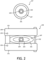
- the deployment system 107 may include a tube or main body 101 through which the guidewire 103 is passed. (See, e.g., cross-section in FIG. 2 ).
- the deployment system 107 may include one or more control or stabilizing handles 105 that are employed, depending on the design to perform a plurality of tasks, e.g., to retract a sheath that supports the endograft 102, to advance a delivery device carrying the endograft 102, to adjust the guidewire 103 or any other useful function depending on the design of the deployment system 107 and the functions its needs to carry out.
- control or stabilizing handles 105 that are employed, depending on the design to perform a plurality of tasks, e.g., to retract a sheath that supports the endograft 102, to advance a delivery device carrying the endograft 102, to adjust the guidewire 103 or any other useful function depending on the design of the deployment system 107 and the functions its needs to carry out.
- the shape sensing system 104 includes one or more optical fibers 126 which are included in the system 104 in a set pattern or patterns.
- the optical fibers 126 connect to the workstation 112.
- the shape sensing system 104 may be included in a lumen of the guidewire 103 and/or other medical components involved in the procedure.
- the OSS fibers 126 or OSS systems 104 are employed to provide a visual representation of the deployable device, such as an endograft or stent.
- the present principles apply to any use of an optical shape sensing fiber 126 for navigation and deployment of the endograft 102, or deployment system 107. While described in terms of the endograft 102, the present principles can also apply to balloon catheters, clips, valves, and other implantables.
- the fibers 126 of the OSS system 104 are integrated within or through the guidewire 103, the deployment system 107 and/or the handle 105 of the deployment system 107.
- the OSS system 104 can be employed for making physical measurements. The measurements may be employed for planning or for placement of the endograft 102.
- the endograft 102 may also include an OSS system 104 to provide position and orientation information for the endograft 102 itself.
- Shape sensing system 104 with fiber optics may be based on fiber optic Bragg grating sensors in one or more optical fibers.
- a fiber optic Bragg grating (FBG) is a short segment of optical fiber that reflects particular wavelengths of light and transmits all others. This is achieved by adding a periodic variation of the refractive index in the fiber core, which generates a wavelength-specific dielectric mirror.
- a fiber Bragg grating can therefore be used as an inline optical filter to block certain wavelengths, or as a wavelength-specific reflector.
- a fundamental principle behind the operation of a fiber Bragg grating is Fresnel reflection at each of the interfaces where the refractive index is changing. For some wavelengths, the reflected light of the various periods is in phase so that constructive interference exists for reflection and, consequently, destructive interference for transmission.
- the Bragg wavelength is sensitive to strain as well as to temperature. This means that Bragg gratings can be used as sensing elements in fiber optical sensors. In an FBG sensor, strain causes a shift in the Bragg wavelength.
- One advantage of this technique is that various sensor elements can be distributed over the length of a fiber. Incorporating three or more cores with various sensors (gauges) along the length of a fiber that is embedded in a structure permits a three dimensional form of such a structure to be precisely determined, typically with better than 1 mm accuracy.
- a multitude of FBG sensors can be located (e.g., 3 or more fiber sensing cores). From the strain measurement of each FBG, the curvature of the structure can be inferred at that position. From the multitude of measured positions, the total three-dimensional form is determined.
- optical shape sensing may be performed in a plurality of ways and is not limited to FBGs or Rayleigh scatter techniques.
- other techniques may include channels etched into the fiber, employing quantum dots for reflection, employing a plurality of separate fibers (e.g., 3 or more) instead of a single multicore fiber or other optical shape sensing techniques.
- Workstation 112 includes a display 118 for viewing internal images of a subject (patient) or volume 131 and may include an image 134 (preoperative or intraoperative images) or an image 136 (OSS data) as an overlay or other rendering registered with the shape sensing system 104 in one or more of the components employed in the procedure.
- Display 118 may also permit a user to interact with the workstation 112 and its components and functions (e.g., touchscreen, graphical user interface, etc.), or any other element within the system 100. This is further facilitated by an interface 120 which may include a keyboard, mouse, a joystick, a haptic device, or any other peripheral or control to permit user feedback from and interaction with the workstation 112.
- an OSS fiber 126 or OSS system 104 or OSS enabled device 103, 105, 107, etc. is coupled to the endograft 102.
- the OSS fiber 126, OSS system 104, etc. is/are registered to a feature or features of the endograft 102.
- geometric information about the graft 102 may be collected and ultimately used to visualize the graft 102.
- a registration module 130 is configured to register the OSS fiber 126 or system 104 to a physical structure (e.g., aneurysm, etc.), other OSS systems 104, images 134, 136, the guidewire 103, the handle 105, the endograft 102, etc.
- a distinctive shape or shape template 128 can be employed to obtain both position and orientation information from the fiber 126. If the fiber 126 takes a predefined and immutable path, the curvature and shape information of that path can be used to identify a unique image to fiber transformation to be stored in memory 116.
- An image processing module 142 is configured to combine images (134) and OSS position data (image 136) for joint or separate display on the display 118.
- the OSS data 136 and the image data (from pre-operative or intraoperative images 134) can be registered and jointly displayed to assist in placement of the endograft 102 (or other stent or implantable device).
- An imaging system 110 may include a fluoroscopy system (x-rays) for collecting real-time visual information about positions of instruments or anatomical features. Images 134 collected with the imaging device 110 may be registered with the OSS data from OSS system 104.
- One step in endograft 102 deployment is the positioning of x-ray visible (radiopaque) markers 132. These are initially positioned when the endograft 102 is advanced on the guidewire 103 to the approximate location. If the endograft can be semi-deployed (as in FEVAR), then the markers 132 are re-used to fine tune the position of the endograft 102. Placement of a three-dimensional endograft 102 within a three-dimensional anatomy is challenging and is typically performed under two-dimensional imaging guidance through x-ray fluoroscopy. As a consequence, misplacement of the endograft 102 can occur, and procedure times can become very long.
- x-ray visible (radiopaque) markers 132 are initially positioned when the endograft 102 is advanced on the guidewire 103 to the approximate location. If the endograft can be semi-deployed (as in FEVAR), then the markers 132 are re-used to fine tune the position of the endograf
- a significant portion of time is spent cannulating the fenestrations of an endograft to ensure alignment with an underlying vasculature.
- the operator attempts to align all fenestrations, or windows, to ensure side branches are not occluded by the main stent graft body.
- the operator must navigate up and into the main stent graft body, then exit the fenestration and enter the side vessel. To do this, the anatomy needs to be seen as well as the position and orientation of the endograft.
- the navigation can be simplified. Then, navigation can be performed using the registered pre-operative (e.g., CT) images for guidance.
- pre-operative e.g., CT
- the system 100 can be used with any type of stent and/or deployment system 107 with limited impact on design of the endograft or the deployment mechanism.
- the OSS system 104 is integrated into the guidewire 103 over which the endograft deployment system 107 is placed.
- the deployment system handle 105 is coupled to the guidewire 103 and any motion of the endograft 102 is tracked with respect to the guidewire 103.
- the endograft 102 is registered to the OSS system 104 in the guidewire 103.
- the guidewire 103 may include a stiff guidewire having diameter of between about 0.014 to about 0.045 inches, and typically about 0.035 inches.
- the present embodiments employ the guidewire 103 with a lumen or channel therein for OSS system 104 to be disposed so that the position and orientation of the guidewire 103 is known.
- a guidewire 103 acts as a 'delivery rail' for the stent deployment tool (107), which passes down a dedicated guidewire lumen within the deployment system 107. Since the guidewire 103 is physically inside the deployment system 107, the reconstructed shape of the guidewire 103 is representative of the shape of the deployment system 107. However, the guidewire 103 is free to rotate and translate inside the deployment system 107, and therefore, the precise position and orientation of the endograft 102, x-ray visible markers 132 or the tip of the deployment system 107 may be unknown.
- the configuration of the deployment system 107 is such that one handle 105 may be connected to the endograft 102 in an axially and torsionally stiff manner. This permits reorientation of the endograft 102 intra-operatively but can also be re-purposed to maintain a registration between the guidewire 103 and the deployment system 107. This can be achieved in several different ways.
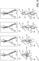
- a clamping mechanism 150 is employed between the guidewire 103 and the deployment system 107.
- the guidewire 103 and the deployment system 107 are shown unconstrained.
- cross-sectional view 159 the guidewire 103 and the deployment system 107 are illustratively shown constrained by the clamping mechanism 150.
- the deployment system 107 is advanced over the guidewire 103 until positioned at an approximately correct desired insertion depth. Once at this location, the clamping mechanism 150 within the deployment system 107 would be activated thus physically coupling the deployment system 107 to the guidewire 103.
- a known feature in the deployment system 107 such as x-ray visible markers
- any subsequent manipulation of the deployment system 107 is known with respect to a shape sensing co-ordinate system.
- the clamping system 150 may include a system that is integrated into the handle 105 of the deployment device 107 or a retrofit system that attaches to the deployment system 107 and then clamps the guidewire 103 proximal to entry into the deployment system 107.
- the clamping mechanism 150 includes a release 152 to permit clamping and reclamping of the guidewire 103 so that there is still the ability to freely manipulate the guidewire 103.
- the release 152 may include an actuated release so that the user does not have to apply the clamping force by hand.
- the clamping mechanism 150 may include chucks 151 that compress a tube 101 of the deployment system 107.
- the chucks may be hingedly connected and employ one or more pivot axes 155.
- the clamping mechanism 150 may be placed at an entry point of the guidewire to the deployment system 107, although it may also be placed at other locations, e.g., at a point distal to the handle 105 (such as at the tip of the deployment system 107, within a spindle of the deployment system, or at the proximal position of a loaded stent). Multiple clamping points along the deployment system 107 (such as proximal and distal to the deployment system 107) may be employed.
- the OSS system 104 may be fixed within the guidewire lumen at the point of the clamping. This may include a temporary or permanent fixation point.
- clamping mechanism 150 is merely illustrative of one technique for fastening the guidewire 103 to the deployment system 107 other mechanisms, such as grips, pins, brakes, etc. may also be employed in accordance with the present principles.
- a coupling feature 160 may be placed on the guidewire 103 and deployment system 107.
- the guidewire 103 has a predefined coupling feature 160 at a certain location along its length. This could be an adjustable torquer or a more permanent feature bonded to the guidewire 103 at a fixed location.
- the deployment system 107 also has a coupling feature 162 at the proximal end of the handle 105 such that when both mating features come in contact they engage and rigidly connect the two devices together.
- the guidewire 103 may clamp onto the handle 105 of the deployment system 107 with no modification to the device handle 105.
- the fixed location could be such that the tip of the guidewire 103 aligns with the tip of the deployment system 107 when the mating components are coupled together, or at any other pre-defined position within or outside the device lumen (103). Defining the positioning of this fixed location with respect to the endograft 102 may be part of a pre-registration protocol.
- the coupling of the two devices could take place at the distal tip of the deployment system 107.
- View 164 shows the coupling features 160 and 162 prior to engagement
- view 166 shows the coupling features 160 and 162 after engagement.
- another embodiment includes a rotational tracking sensor 190 that tracks rotation between the handle 105 and the guidewire 103.
- sensors 190 into the handle 105 or attachment piece such that the guidewire 103 connects to the deployment system 107 in a manner which enables the relative rotation and translation of the two devices to be measured.
- This embodiment may include an optical encoder (190) (or similar mechanism) within the handle 105 to measure rotation, and a linear potentiometer 191 (or similar mechanism) embedded within the handle 105 but which couples to the guidewire 103.
- another embodiment tracks the handle 105 and the guidewire 103 using a template 192 with the OSS system 104, using a known shape in the template 192 within the guidewire lumen. If the guidewire 103 is forced to pass through a specific shape within the handle of the deployment system 107, its position and orientation with respect to the system can be identified.
- the endograft 102 may be registered to the guidewire 103 in a number of ways. These may include registering the OSS system 104 in the guidewire 103 to x-ray visible markers 202 on the stent or endograft 102. This can be performed using an x-ray registration that employs a tip of the guidewire 103 and the markers 202 visible in the x-ray image to determine their relationship. In some cases, the tip of the guidewire 103 may not be visible within the same x-ray image as the stent 102.
- An alternative way to perform this registration is to make unique x-ray visible bands 204 on the guidewire 103 along its distal length so that one of those bands is likely to be in close proximity to the endograft or stent 102, and thus enable registration. Additional methods of registering the OSS system 104 are also contemplated.
- a virtual representation of the markers 202, 204 can be displayed within the 3D visualization framework (e.g., on display 118, FIG. 1 ). Then, as the deployment system 107 is manipulated, the position of the markers 202, 204 can be updated accordingly. Similarly a 3D model of the stent graft 102 can be deformed according to the known positions of the markers 202, 204 and the OSS shape data from OSS system 104.
- a 2D overlay of a fluoro image of the stent 102 can be displayed to the user and adapted based on the guidewire position and orientation. This is particularly useful, for example, in FEVAR when the main body stent has been partially deployed and navigation is underway to cannulate the side vessels using OSS-enabled devices. In this situation, knowing the position of the fenestration markers 202 on the stent 102 can provide additional information for navigating through the stent 102 and into side vessels. The stent 102 can be visualized using the information provided by tracking the guidewire 103.
- a virtual representation of the stent graft as a full 3D model of the stent may be employed in various stages of deployment. Such a representation would clearly provide a further simplified navigation task. Especially in the case of stenting, where it is important to carefully maintain mechanical properties, it may be preferrable to not interfere with the functional properties of the endograft 102. In addition, there are typically many types of endograft 102 that use only one type of deployment handle 105. An OSS system 104 may be employed as a retrofit attachment onto the handle. In this way, multiple stents can be addressed by one design.
- another embodiment tracks the handle 105 and the guidewire 103 using a same OSS system 104.
- a proximal end of the OSS system 104 exits the guidewire 103 and is connected to a fixed point (attachment point) 174 on the deployment system 107 before returning to a launch fixture 170.
- the location of this fixed point 174 is preferably on the distal handle 105 of the deployment system 107 since this rigidly coupled to a main backbone of the system 107 and thus the location of the endograft 102.
- FIG. 8 another embodiment tracks the handle 105 and the guidewire 103 using different OSS systems 104.
- a second OSS system 104' is attached to a fixed point 184 on the deployment system 107 and registered to a shape sensing co-ordinate system.
- the location of this fixed point 184 is preferably at a point on the handle 105 of the deployment system 107 since this is rigidly coupled to a main backbone of the system 107 and thus the location of the endograft 102.
- This configuration permits the guidewire 103 to be rotated and translated with respect to the deployment system 107.
- a clip-on attachment 302 (or set of attachments) may be included to connect one or more OSS systems 104 to a handle or handles 105 of the deployment system 107.
- a method for registering the stent 102 to the OSS system 104 is also needed.
- the clip-on attachment 302 that connects to the deployment system 107 can provide a simple way to enable visualization of the endograft deployment process. Motions at a proximal portion of the deployment system 107 directly map to changes in the stent position and state of deployment.
- the clip-on attachment 302 includes adhesive strips or pieces that are employed that attach to the OSS system 104 and are fixed to the proximal and distal handles 105 of the deployment system 107.
- the OSS system 104 returns back to a launch base or fixture 308 where its origin resides.
- Clips 302 can be removed and re-applied for another stent deployment within a same procedure.
- the clips 302 can be comprised of a mechanical fixation device (e.g., clip, toggle clamp, spring clasp, etc.), an adhesive, a magnetic attachment, a band or other attachment device.
- the position of the stent graft 102, the orientation of the stent graft 102 and the state of deployment need to be known. There are three primary features that need be known about the stent to provide a meaningful visualization. It is assumed that a shape sensed guidewire 103 is being used as part of the deployment process. This guidewire 103 can provide part of the information to determine the position of the stent 102. In some cases, the guidewire 103 may not be coupled to the deployment system 107 so it does not provide information about the orientation.
- the clip-on attachment 302 can sense the orientation of a retaining ring of the stent graft 102 (or whichever portion of the stent graft that is rigidly attached to the deployment system 107) because the orientation of the distal portion of the handle 105 is directly coupled to the orientation of the attachment site of the stent graft 102 (very stiff torsionally). This is what enables the fine manipulation of the stent graft 102 during deployment. Therefore, by sensing the position of the distal deployment handle 105, the orientation of the attachment point on the stent graft 102 can be extracted.
- the clip-on attachment 302 may provide information about the state of deployment of the stent graft 102 by measuring a relative position of actuating elements (e.g., handles 105) of the stent deployment system 107. As shown in FIG. 9 , separation between the distal and proximal handles 105 on the deployment system directly relates to how many individual stents or stent length that has been released. Visualization of the stent deployment using shape sensing on the handles 105 with a clip-on attachment 302 includes OSS system 104 attached to both distal and proximal handles.
- actuating elements e.g., handles 105
- the clip-on attachment 302 provides the same functionality as the embodiments described above without the need for handle modifications.
- the clip-on attachment 302 to the handle 105 can be done with a different OSS system 104 than that employed for the guidewire 103, or by using the OSS system 104 after leaving from a proximal portion of the guidewire 103.
- an illustrative deployment system 107 is shown along with a magnified view of an adhesive clip-on attachment 302'.
- the adhesive or clip attachment 302' can also be used to sense a distal portion of the deployment system 107.
- This clip 302' may include an adhesive attachment or patch 312 that couples the OSS system 104 to the outside of the deployment system 107.
- This adhesive patch 312 can also have a radiopaque marker 314 integrated into it for registration purposes.
- the OSS system 104 travels back from the deployment system 107 to a launch fixture 308 outside the body. Alternatively, it could travel back to an attachment point on the handle 105.
- the Information for Use (IFU) for each stent 102 includes a step at the beginning of the process where the stent 102 is visualized under x-ray by the operator, rotated based on the x-ray visible markers (202) present, and then mentally mapped to an indicator 322 on the handle 105 so as to remember an 'optimal' orientation for deployment.
- IFU Information for Use
- the operator After navigating, the operator then returns the handle 105 to the optimal orientation (as indicated by a recalled position of the dot 322).
- This same procedure can be used following attachment of the OSS system 104.
- the stent 102 is rotated until it is fully in plane (based on the marker bands 202) and then that position is used to map the OSS system 104 to the stent 102 in orientation. This could be done manually or robotically.
- the next important registration is in position. This is principally the distance along the deployment system 107 between the stent 102 and the OSS clip 302 onto the handle 105. Specifically, the position of the x-ray visible markers (202) within the stent 102 should be known. This distance can be identified using a multitude of different methods. For example, one embodiment would include a priori knowledge of the mechanical construction of the stent deployment system 107. Another embodiment includes determining the distance under x-ray guidance. If the shape sensing base is registered to the x-ray system then the stent deployment system 107 can be placed straight and with the stent visible under x-ray.
- the marker bands (204) can be selected in the image and then the distance between the clips (302) on the handle (105) and the marker bands will be known. This can be done prior to deployment as the marker bands are visible at that time.
- Another embodiment employs an x-ray image of the stent deployment system 107 that can be used to identify the offset between the deployment system tip and the marker bands (204) on the stent graft 102. From the known orientation, position, and state of deployment, a model of the endograft can be generated and displayed to the user.
- the present principles can be applied to any use of an optical shape sensing fiber or system for navigation and deployment of a stent, stent-graft, or stent deployment system.
- the present principles can also be applied to any stent and balloon, i.e., to any over the wire therapy device, to track the position of the device in the vessel, to help position the device and deliver therapy with less x-ray and less contrast media volume.
- a stiff guidewire would likely be replaced by a more flexible wire, either or both may be OSS tracked.
- an endograft is deployed under fluoroscopic or other guidance including, but not limited to procedures, such as, e.g., endovascular aneurysm repair (EVAR), branch-fenestrated EVAR (BEVAR), percutaneous EVAR (PEVAR), thoracic EVAR (TEVAR), fenestrated EVAR (FEVAR), etc.
- EVAR endovascular aneurysm repair
- BEVAR branch-fenestrated EVAR
- PEVAR percutaneous EVAR
- TEVAR thoracic EVAR
- FEVAR fenestrated EVAR
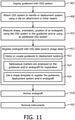
- a guide wire having an optical shape sensing (OSS) system within a lumen of the guide wire is deployed.
- the guide wire is configured to deliver an endograft into a vessel.
- the guide wire may be disposed within a deployment system or tool.
- the deployment system or tool may have relative motion (e.g., free rotation, measured rotation, etc.) with respect to the guidewire or the relative motion may be constrained.
- the deployment system and the guidewire may be clamped together or coupled together when engaging at a particular point, etc.
- the OSS system may be attached to the at least one handle or deployment system using a clip-on attachment device or other means.
- the deployment system may include two handles and the OSS system may be attached between the two handles to measure relative distance between the handles using the OSS system.
- shape, position and/or orientation of the guide wire are measured using the OSS system to identify a shape, position and orientation of the endograft during deployment.
- the shape, position and/or orientation of the handle may be measured with the OSS system inside the guide wire or may be measured using an additional OSS system.
- the endograft is registered with OSS data and/or with image data of the vessel where the endograft is placed.
- the guidewire may be clamped or coupled to the deployment system to prevent relative motion therebetween.
- the deployment system may include at least one handle.
- the OSS system may also be coupled to the at least one handle.
- the endograft is registered with the guide wire using one or more radiopaque markers along a length of the guidewire and/or on the endograft.
- the guidewire may include a shape template and the the OSS data is registered to the image data using the shape template.
- the shape template includes a distinctive shape that can be matched between OSS data and image data to register one or more of the deployment system, the guidewire, the stent, etc.
- the endograft is anchored in the blood vessel.
- the guidewire and the OSS system are removed from the vessel.
Claims (15)
- Ein System zum Bereitstellen eines medizinischen Geräts, das Folgendes umfasst:ein Hauptgehäuse (101);einen Führungsdraht (103), der durch das Hauptgehäuse geführt werden kann und ein Lumen aufweist; undein optisches Formabtastungssystem (OSS) (104), das durch das Lumen im Führungsdraht geführt werden kann, wobei das OSS-System mindestens jeweils die Form, Position oder Ausrichtung eines für ein anatomisches Merkmal eingesetzten medizinischen Geräts misst und optische Formabtastungsdaten ausgibt, die mithilfe der Reflexionen innerhalb eines Lichtwellenleiters des OSS-Systems abgerufen werden und eine Form des Lichtwellenleiters angeben,dadurch gekennzeichnet,dass der Führungsdraht (103) zentral im Hauptgehäuse (101) angeordnet ist, unddass das OSS-System (104) zentral im Lumen des Führungsdrahts (103) angeordnet ist.
- Das Bereitstellungssystem gemäß Anspruch 1, wobei der Führungsdraht (103) mithilfe einer Formvorlage (128) verformt wird, um die Position in den optischen Formabtastungsdaten entlang des Führungsdrahts zu erfassen.
- Das Bereitstellungssystem gemäß Anspruch 1, das zudem mindestens einen Griff (105) umfasst, der mit dem Hauptgehäuse verbunden ist, wobei der mindestens eine Griff eine Befestigungsposition für das aus dem Führungsdraht austretende OSS-System umfasst.
- Das Bereitstellungssystem gemäß Anspruch 1, das zudem mindestens einen Griff (105) umfasst, der mit dem Hauptgehäuse verbunden ist, wobei der mindestens eine Griff eine Befestigungsposition für ein zusätzliches OSS-System umfasst.
- Das Bereitstellungssystem gemäß Anspruch 1, das zudem einen Klemmmechanismus (150) umfasst, mit dem das Hauptgehäuse an den Führungsdraht geklemmt wird.
- Das Bereitstellungssystem gemäß Anspruch 1, das zudem ein erstes Verbindungselement (162) am Hauptgehäuse sowie ein zweites Verbindungselement (160) am Führungsdraht umfasst, wobei das erste Verbindungselement und das zweite Verbindungselement ineinander greifen, um eine Verbindung herzustellen und sich nicht gegeneinander zu bewegen.
- Das Bereitstellungssystem gemäß Anspruch 1, das zudem ein Gerät zum Messung der Drehung (190) zwischen dem Hauptgehäuse und dem Führungsdraht umfasst, das die Drehung zwischen dem Hauptgehäuse und dem Führungsdraht misst.
- Das Bereitstellungssystem gemäß Anspruch 1, das zudem Folgendes umfasst:ein Endotransplantat; undröntgendichte Markierungen (204) auf dem Führungsdraht, um ein Erfassen zwischen dem Führungsdraht und dem Endotransplantat zu ermöglichen.
- Das Bereitstellungssystem gemäß Anspruch 1, das zudem mindestens eine Klemmbefestigung (174) umfasst, mit der das OSS-System am Bediengriff des Bereitstellungssystems befestigt wird.
- Das Bereitstellungssystem gemäß Anspruch 9, wobei die mindestens eine Klemmbefestigung einen haftenden Abschnitt (312) aufweist, der mit dem Bereitstellungssystem verbunden ist, um das OSS-System zu befestigen, und wobei der haftende Abschnitt ein röntgendichtes Element umfasst.
- Das Bereitstellungssystem gemäß Anspruch 1, wobei es sich beim Bereitstellungssystem um ein Endotransplantat-Bereitstellungssystem (107) oder ein Bereitstellungssystem handelt, das eine Mitralklemme, eine Klappe oder einen Ballonkatheter umfasst.
- Ein Endotransplantat-Bereitstellungssystem,das Folgendes umfasst:eine Arbeitsstation (112) mit einem Prozessor und einem Speicher;ein optisches Formabtastungsmodul (115), das im Speicher gespeichert wird und optische Formabtastungsdaten interpretiert;ein Bereitstellungssystem (107) gemäß Anspruch 1, wobei das Hauptgehäuse eine Röhre umfasst, und wobei der Führungsdraht (103) durch die Röhre geführt werden kann;undein Erfassungsmodul (130), das die optischen Formabtastungsdaten in präoperativen oder intraoperativen Bildern erfasst.
- Das Endotransplantat-Bereitstellungssystem gemäß Anspruch 12, wobei der Führungsdraht mithilfe einer Formvorlage (128) verformt wird, um die Position in den Formdaten entlang des Führungsdrahts zu erfassen.
- Das Endotransplantat-Bereitstellungssystem gemäß Anspruch 12, das zudem mindestens einen Griff (105) umfasst, der mit der Röhre verbunden ist, wobei der mindestens eine Griff eine Befestigungsposition für das aus dem Führungsdraht austretende OSS-System umfasst.
- Das Endotransplantat-Bereitstellungssystem gemäß Anspruch 12, das zudem mindestens einen Griff (105) umfasst, der mit der Röhre verbunden ist, wobei der mindestens eine Griff eine Befestigungsposition für ein zusätzliches OSS-System umfasst.
Applications Claiming Priority (2)
| Application Number | Priority Date | Filing Date | Title |
|---|---|---|---|
| US201562106267P | 2015-01-22 | 2015-01-22 | |
| PCT/IB2015/060063 WO2016116796A1 (en) | 2015-01-22 | 2015-12-31 | Device visualization through optical shape sensing of a guidewire |
Publications (2)
| Publication Number | Publication Date |
|---|---|
| EP3247259A1 EP3247259A1 (de) | 2017-11-29 |
| EP3247259B1 true EP3247259B1 (de) | 2022-03-09 |
Family
ID=55174686
Family Applications (1)
| Application Number | Title | Priority Date | Filing Date |
|---|---|---|---|
| EP15825970.5A Active EP3247259B1 (de) | 2015-01-22 | 2015-12-31 | Visualisierung einer vorrichtung durch optische formmessung eines führungsdrahtes |
Country Status (5)
| Country | Link |
|---|---|
| US (2) | US11553966B2 (de) |
| EP (1) | EP3247259B1 (de) |
| JP (2) | JP2018511353A (de) |
| CN (1) | CN107205810B (de) |
| WO (1) | WO2016116796A1 (de) |
Families Citing this family (10)
| Publication number | Priority date | Publication date | Assignee | Title |
|---|---|---|---|---|
| US11553966B2 (en) * | 2015-01-22 | 2023-01-17 | Koninklijke Philips N.V. | Device visualization through optical shape sensing of a guidewire |
| EP3355780A1 (de) * | 2015-10-02 | 2018-08-08 | Koninklijke Philips N.V. | Hub für vorrichtungsnavigation mit optischem formerfasstem führungsdraht |
| WO2018096491A1 (en) * | 2016-11-28 | 2018-05-31 | Koninklijke Philips N.V. | Shape sensing of multiple over-the-wire devices |
| CN110049741B (zh) * | 2016-12-05 | 2023-07-25 | 皇家飞利浦有限公司 | 用于利用形状感测导丝确定非形状感测介入设备的长度的系统和方法 |
| CN107527543B (zh) * | 2017-09-28 | 2020-10-27 | 北京理工大学 | 一种手术模拟设备及手术模拟系统 |
| US11199485B1 (en) * | 2018-08-03 | 2021-12-14 | National Technology & Engineering Solutions Of Sandia, Llc | Friction testing and torque sensing systems |
| US11413063B2 (en) * | 2019-06-18 | 2022-08-16 | Boston Scientific Scimed, Inc. | Atherectomy system with guidewire detection |
| CN110517550A (zh) * | 2019-08-30 | 2019-11-29 | 深圳妙创医学技术有限公司 | 一种置管长度测量机构及医疗置管模拟设备 |
| CN110575603A (zh) * | 2019-10-14 | 2019-12-17 | 苏州法兰克曼医疗器械有限公司 | 一种具有可视功能的导丝输送装置 |
| JP2021081223A (ja) * | 2019-11-15 | 2021-05-27 | ナノコイル株式会社 | スマートガイドワイヤおよびガイドワイヤ操作システム |
Family Cites Families (23)
| Publication number | Priority date | Publication date | Assignee | Title |
|---|---|---|---|---|
| ES2202580T3 (es) | 1996-02-22 | 2004-04-01 | Sdgi Holdings, Inc. | Dispositivo de fusion intercorporal. |
| US6010449A (en) * | 1997-02-28 | 2000-01-04 | Lumend, Inc. | Intravascular catheter system for treating a vascular occlusion |
| US6567690B2 (en) * | 2000-10-16 | 2003-05-20 | Cole Giller | Method and apparatus for probe localization in brain matter |
| US7524316B2 (en) * | 2002-10-31 | 2009-04-28 | Cooltouch, Inc. | Endovenous closure of varicose veins with mid infrared laser |
| JP4933450B2 (ja) | 2005-01-10 | 2012-05-16 | タヘリ ラドュカ エルエルシー | インプラント可能装置を体内で展開するための機器および方法 |
| JP4972639B2 (ja) * | 2005-05-06 | 2012-07-11 | バソノバ・インコーポレイテッド | 血管内デバイスを誘導し及び位置決めするための方法及び装置 |
| US20090187108A1 (en) * | 2006-09-29 | 2009-07-23 | Cornova, Inc. | Systems and methods for analysis and treatment of a body lumen |
| JP5747042B2 (ja) * | 2009-12-22 | 2015-07-08 | サニーブルック ヘルス サイエンスセンター | Mriで画像化できる介入機器用追跡装置 |
| JP5997157B2 (ja) * | 2010-09-01 | 2016-09-28 | コーニンクレッカ フィリップス エヌ ヴェKoninklijke Philips N.V. | バックロード可能な光学形状検知ガイドワイヤ |
| US8764683B2 (en) * | 2010-12-29 | 2014-07-01 | Mediguide Ltd. | Medical device guidewire with a position sensor |
| WO2013024418A1 (en) * | 2011-08-16 | 2013-02-21 | Koninklijke Philips Electronics N.V. | Curved multi-planar reconstruction using fiber optic shape data |
| US9405078B2 (en) * | 2011-08-30 | 2016-08-02 | Opsens Inc. | Method for disposable guidewire optical connection |
| MX342395B (es) | 2011-09-02 | 2016-09-28 | Koninklijke Philips Nv | Informacion de insercion y egreso de dispositivo medico utilizando deteccion distribuida de temperatura con fibra optica. |
| US9782282B2 (en) | 2011-11-14 | 2017-10-10 | W. L. Gore & Associates, Inc. | External steerable fiber for use in endoluminal deployment of expandable devices |
| AT512834B1 (de) | 2012-05-08 | 2014-05-15 | Amst Systemtechnik Gmbh | Manipulatoranordnung und Bewegungsvorrichtung |
| RU2686954C2 (ru) | 2012-06-28 | 2019-05-06 | Конинклейке Филипс Н.В. | Навигация с помощью оптоволоконного датчика для визуализации и мониторинга сосудов |
| US9855129B2 (en) | 2012-10-31 | 2018-01-02 | Cook Medical Technologies Llc | Multi-level suture attachments for coupling a stent to graft material |
| US11406498B2 (en) * | 2012-12-20 | 2022-08-09 | Philips Image Guided Therapy Corporation | Implant delivery system and implants |
| CA2895837A1 (en) | 2012-12-20 | 2014-06-26 | David Goodman | Implant delivery system and implants |
| JP6411459B2 (ja) * | 2013-04-12 | 2018-10-24 | コーニンクレッカ フィリップス エヌ ヴェKoninklijke Philips N.V. | 冠血流予備量比シミュレーションに対する形状感知超音波プローブ |
| US9592095B2 (en) * | 2013-05-16 | 2017-03-14 | Intuitive Surgical Operations, Inc. | Systems and methods for robotic medical system integration with external imaging |
| US20150099942A1 (en) * | 2013-10-04 | 2015-04-09 | Volcano Corporation | Vascular securement catheter with imaging |
| US11553966B2 (en) * | 2015-01-22 | 2023-01-17 | Koninklijke Philips N.V. | Device visualization through optical shape sensing of a guidewire |
-
2015
- 2015-12-31 US US15/544,925 patent/US11553966B2/en active Active
- 2015-12-31 WO PCT/IB2015/060063 patent/WO2016116796A1/en active Application Filing
- 2015-12-31 JP JP2017537957A patent/JP2018511353A/ja active Pending
- 2015-12-31 CN CN201580074160.3A patent/CN107205810B/zh active Active
- 2015-12-31 EP EP15825970.5A patent/EP3247259B1/de active Active
-
2020
- 2020-12-08 JP JP2020203276A patent/JP7098703B2/ja active Active
-
2022
- 2022-09-06 US US17/903,340 patent/US20230000567A1/en active Pending
Also Published As
| Publication number | Publication date |
|---|---|
| JP2018511353A (ja) | 2018-04-26 |
| CN107205810B (zh) | 2021-10-29 |
| JP2021041231A (ja) | 2021-03-18 |
| US20180014886A1 (en) | 2018-01-18 |
| WO2016116796A1 (en) | 2016-07-28 |
| CN107205810A (zh) | 2017-09-26 |
| US20230000567A1 (en) | 2023-01-05 |
| EP3247259A1 (de) | 2017-11-29 |
| JP7098703B2 (ja) | 2022-07-11 |
| US11553966B2 (en) | 2023-01-17 |
Similar Documents
| Publication | Publication Date | Title |
|---|---|---|
| US20230000567A1 (en) | Device visualization through optical shape sensing of a guidewire | |
| CN108135531B (zh) | 用于利用光学形状感测的导丝来放置设备的衬套 | |
| US11690975B2 (en) | Hub for device navigation with optical shape sensed guidewire | |
| CN107205785B (zh) | 利用光学形状感测的腔内移植物可视化 | |
| JP2018502646A5 (de) | ||
| WO2018104162A1 (en) | Systems and methods for determining the length of a non-shape-sensed interventional device with a shape-sensed guidewire and determining a state of the guidewire with respect to an interventional device | |
| CN109475725B (zh) | 包括形状感测光纤的球囊导管 | |
| US11887236B2 (en) | Animated position display of an OSS interventional device | |
| US11344440B2 (en) | Endograft visualization with pre-integrated or removable optical shape sensing attachments |
Legal Events
| Date | Code | Title | Description |
|---|---|---|---|
| STAA | Information on the status of an ep patent application or granted ep patent |
Free format text: STATUS: THE INTERNATIONAL PUBLICATION HAS BEEN MADE |
|
| PUAI | Public reference made under article 153(3) epc to a published international application that has entered the european phase |
Free format text: ORIGINAL CODE: 0009012 |
|
| STAA | Information on the status of an ep patent application or granted ep patent |
Free format text: STATUS: REQUEST FOR EXAMINATION WAS MADE |
|
| 17P | Request for examination filed |
Effective date: 20170822 |
|
| AK | Designated contracting states |
Kind code of ref document: A1 Designated state(s): AL AT BE BG CH CY CZ DE DK EE ES FI FR GB GR HR HU IE IS IT LI LT LU LV MC MK MT NL NO PL PT RO RS SE SI SK SM TR |
|
| AX | Request for extension of the european patent |
Extension state: BA ME |
|
| DAV | Request for validation of the european patent (deleted) | ||
| DAX | Request for extension of the european patent (deleted) | ||
| RAP1 | Party data changed (applicant data changed or rights of an application transferred) |
Owner name: KONINKLIJKE PHILIPS N.V. |
|
| GRAP | Despatch of communication of intention to grant a patent |
Free format text: ORIGINAL CODE: EPIDOSNIGR1 |
|
| STAA | Information on the status of an ep patent application or granted ep patent |
Free format text: STATUS: GRANT OF PATENT IS INTENDED |
|
| INTG | Intention to grant announced |
Effective date: 20211007 |
|
| GRAS | Grant fee paid |
Free format text: ORIGINAL CODE: EPIDOSNIGR3 |
|
| GRAA | (expected) grant |
Free format text: ORIGINAL CODE: 0009210 |
|
| STAA | Information on the status of an ep patent application or granted ep patent |
Free format text: STATUS: THE PATENT HAS BEEN GRANTED |
|
| AK | Designated contracting states |
Kind code of ref document: B1 Designated state(s): AL AT BE BG CH CY CZ DE DK EE ES FI FR GB GR HR HU IE IS IT LI LT LU LV MC MK MT NL NO PL PT RO RS SE SI SK SM TR |
|
| REG | Reference to a national code |
Ref country code: GB Ref legal event code: FG4D |
|
| REG | Reference to a national code |
Ref country code: CH Ref legal event code: EP Ref country code: AT Ref legal event code: REF Ref document number: 1473466 Country of ref document: AT Kind code of ref document: T Effective date: 20220315 |
|
| REG | Reference to a national code |
Ref country code: IE Ref legal event code: FG4D |
|
| REG | Reference to a national code |
Ref country code: DE Ref legal event code: R096 Ref document number: 602015077446 Country of ref document: DE |
|
| REG | Reference to a national code |
Ref country code: LT Ref legal event code: MG9D |
|
| REG | Reference to a national code |
Ref country code: NL Ref legal event code: MP Effective date: 20220309 |
|
| PG25 | Lapsed in a contracting state [announced via postgrant information from national office to epo] |
Ref country code: SE Free format text: LAPSE BECAUSE OF FAILURE TO SUBMIT A TRANSLATION OF THE DESCRIPTION OR TO PAY THE FEE WITHIN THE PRESCRIBED TIME-LIMIT Effective date: 20220309 Ref country code: RS Free format text: LAPSE BECAUSE OF FAILURE TO SUBMIT A TRANSLATION OF THE DESCRIPTION OR TO PAY THE FEE WITHIN THE PRESCRIBED TIME-LIMIT Effective date: 20220309 Ref country code: NO Free format text: LAPSE BECAUSE OF FAILURE TO SUBMIT A TRANSLATION OF THE DESCRIPTION OR TO PAY THE FEE WITHIN THE PRESCRIBED TIME-LIMIT Effective date: 20220609 Ref country code: LT Free format text: LAPSE BECAUSE OF FAILURE TO SUBMIT A TRANSLATION OF THE DESCRIPTION OR TO PAY THE FEE WITHIN THE PRESCRIBED TIME-LIMIT Effective date: 20220309 Ref country code: HR Free format text: LAPSE BECAUSE OF FAILURE TO SUBMIT A TRANSLATION OF THE DESCRIPTION OR TO PAY THE FEE WITHIN THE PRESCRIBED TIME-LIMIT Effective date: 20220309 Ref country code: BG Free format text: LAPSE BECAUSE OF FAILURE TO SUBMIT A TRANSLATION OF THE DESCRIPTION OR TO PAY THE FEE WITHIN THE PRESCRIBED TIME-LIMIT Effective date: 20220609 |
|
| REG | Reference to a national code |
Ref country code: AT Ref legal event code: MK05 Ref document number: 1473466 Country of ref document: AT Kind code of ref document: T Effective date: 20220309 |
|
| PG25 | Lapsed in a contracting state [announced via postgrant information from national office to epo] |
Ref country code: LV Free format text: LAPSE BECAUSE OF FAILURE TO SUBMIT A TRANSLATION OF THE DESCRIPTION OR TO PAY THE FEE WITHIN THE PRESCRIBED TIME-LIMIT Effective date: 20220309 Ref country code: GR Free format text: LAPSE BECAUSE OF FAILURE TO SUBMIT A TRANSLATION OF THE DESCRIPTION OR TO PAY THE FEE WITHIN THE PRESCRIBED TIME-LIMIT Effective date: 20220610 Ref country code: FI Free format text: LAPSE BECAUSE OF FAILURE TO SUBMIT A TRANSLATION OF THE DESCRIPTION OR TO PAY THE FEE WITHIN THE PRESCRIBED TIME-LIMIT Effective date: 20220309 |
|
| PG25 | Lapsed in a contracting state [announced via postgrant information from national office to epo] |
Ref country code: NL Free format text: LAPSE BECAUSE OF FAILURE TO SUBMIT A TRANSLATION OF THE DESCRIPTION OR TO PAY THE FEE WITHIN THE PRESCRIBED TIME-LIMIT Effective date: 20220309 |
|
| PG25 | Lapsed in a contracting state [announced via postgrant information from national office to epo] |
Ref country code: SM Free format text: LAPSE BECAUSE OF FAILURE TO SUBMIT A TRANSLATION OF THE DESCRIPTION OR TO PAY THE FEE WITHIN THE PRESCRIBED TIME-LIMIT Effective date: 20220309 Ref country code: SK Free format text: LAPSE BECAUSE OF FAILURE TO SUBMIT A TRANSLATION OF THE DESCRIPTION OR TO PAY THE FEE WITHIN THE PRESCRIBED TIME-LIMIT Effective date: 20220309 Ref country code: RO Free format text: LAPSE BECAUSE OF FAILURE TO SUBMIT A TRANSLATION OF THE DESCRIPTION OR TO PAY THE FEE WITHIN THE PRESCRIBED TIME-LIMIT Effective date: 20220309 Ref country code: PT Free format text: LAPSE BECAUSE OF FAILURE TO SUBMIT A TRANSLATION OF THE DESCRIPTION OR TO PAY THE FEE WITHIN THE PRESCRIBED TIME-LIMIT Effective date: 20220711 Ref country code: ES Free format text: LAPSE BECAUSE OF FAILURE TO SUBMIT A TRANSLATION OF THE DESCRIPTION OR TO PAY THE FEE WITHIN THE PRESCRIBED TIME-LIMIT Effective date: 20220309 Ref country code: EE Free format text: LAPSE BECAUSE OF FAILURE TO SUBMIT A TRANSLATION OF THE DESCRIPTION OR TO PAY THE FEE WITHIN THE PRESCRIBED TIME-LIMIT Effective date: 20220309 Ref country code: CZ Free format text: LAPSE BECAUSE OF FAILURE TO SUBMIT A TRANSLATION OF THE DESCRIPTION OR TO PAY THE FEE WITHIN THE PRESCRIBED TIME-LIMIT Effective date: 20220309 Ref country code: AT Free format text: LAPSE BECAUSE OF FAILURE TO SUBMIT A TRANSLATION OF THE DESCRIPTION OR TO PAY THE FEE WITHIN THE PRESCRIBED TIME-LIMIT Effective date: 20220309 |
|
| PG25 | Lapsed in a contracting state [announced via postgrant information from national office to epo] |
Ref country code: PL Free format text: LAPSE BECAUSE OF FAILURE TO SUBMIT A TRANSLATION OF THE DESCRIPTION OR TO PAY THE FEE WITHIN THE PRESCRIBED TIME-LIMIT Effective date: 20220309 Ref country code: IS Free format text: LAPSE BECAUSE OF FAILURE TO SUBMIT A TRANSLATION OF THE DESCRIPTION OR TO PAY THE FEE WITHIN THE PRESCRIBED TIME-LIMIT Effective date: 20220709 Ref country code: AL Free format text: LAPSE BECAUSE OF FAILURE TO SUBMIT A TRANSLATION OF THE DESCRIPTION OR TO PAY THE FEE WITHIN THE PRESCRIBED TIME-LIMIT Effective date: 20220309 |
|
| REG | Reference to a national code |
Ref country code: DE Ref legal event code: R097 Ref document number: 602015077446 Country of ref document: DE |
|
| PLBE | No opposition filed within time limit |
Free format text: ORIGINAL CODE: 0009261 |
|
| STAA | Information on the status of an ep patent application or granted ep patent |
Free format text: STATUS: NO OPPOSITION FILED WITHIN TIME LIMIT |
|
| PG25 | Lapsed in a contracting state [announced via postgrant information from national office to epo] |
Ref country code: DK Free format text: LAPSE BECAUSE OF FAILURE TO SUBMIT A TRANSLATION OF THE DESCRIPTION OR TO PAY THE FEE WITHIN THE PRESCRIBED TIME-LIMIT Effective date: 20220309 |
|
| 26N | No opposition filed |
Effective date: 20221212 |
|
| PG25 | Lapsed in a contracting state [announced via postgrant information from national office to epo] |
Ref country code: SI Free format text: LAPSE BECAUSE OF FAILURE TO SUBMIT A TRANSLATION OF THE DESCRIPTION OR TO PAY THE FEE WITHIN THE PRESCRIBED TIME-LIMIT Effective date: 20220309 |
|
| PG25 | Lapsed in a contracting state [announced via postgrant information from national office to epo] |
Ref country code: IT Free format text: LAPSE BECAUSE OF FAILURE TO SUBMIT A TRANSLATION OF THE DESCRIPTION OR TO PAY THE FEE WITHIN THE PRESCRIBED TIME-LIMIT Effective date: 20220309 |
|
| REG | Reference to a national code |
Ref country code: CH Ref legal event code: PL |
|
| REG | Reference to a national code |
Ref country code: BE Ref legal event code: MM Effective date: 20221231 |
|
| PG25 | Lapsed in a contracting state [announced via postgrant information from national office to epo] |
Ref country code: LU Free format text: LAPSE BECAUSE OF NON-PAYMENT OF DUE FEES Effective date: 20221231 |
|
| PG25 | Lapsed in a contracting state [announced via postgrant information from national office to epo] |
Ref country code: LI Free format text: LAPSE BECAUSE OF NON-PAYMENT OF DUE FEES Effective date: 20221231 Ref country code: IE Free format text: LAPSE BECAUSE OF NON-PAYMENT OF DUE FEES Effective date: 20221231 Ref country code: CH Free format text: LAPSE BECAUSE OF NON-PAYMENT OF DUE FEES Effective date: 20221231 |
|
| PG25 | Lapsed in a contracting state [announced via postgrant information from national office to epo] |
Ref country code: BE Free format text: LAPSE BECAUSE OF NON-PAYMENT OF DUE FEES Effective date: 20221231 |
|
| PGFP | Annual fee paid to national office [announced via postgrant information from national office to epo] |
Ref country code: GB Payment date: 20231219 Year of fee payment: 9 |
|
| PGFP | Annual fee paid to national office [announced via postgrant information from national office to epo] |
Ref country code: FR Payment date: 20231226 Year of fee payment: 9 |
|
| PG25 | Lapsed in a contracting state [announced via postgrant information from national office to epo] |
Ref country code: HU Free format text: LAPSE BECAUSE OF FAILURE TO SUBMIT A TRANSLATION OF THE DESCRIPTION OR TO PAY THE FEE WITHIN THE PRESCRIBED TIME-LIMIT; INVALID AB INITIO Effective date: 20151231 |
|
| PG25 | Lapsed in a contracting state [announced via postgrant information from national office to epo] |
Ref country code: CY Free format text: LAPSE BECAUSE OF FAILURE TO SUBMIT A TRANSLATION OF THE DESCRIPTION OR TO PAY THE FEE WITHIN THE PRESCRIBED TIME-LIMIT Effective date: 20220309 |
|
| PGFP | Annual fee paid to national office [announced via postgrant information from national office to epo] |
Ref country code: DE Payment date: 20231227 Year of fee payment: 9 |