US11690975B2 - Hub for device navigation with optical shape sensed guidewire - Google Patents
Hub for device navigation with optical shape sensed guidewire Download PDFInfo
- Publication number
- US11690975B2 US11690975B2 US15/763,143 US201615763143A US11690975B2 US 11690975 B2 US11690975 B2 US 11690975B2 US 201615763143 A US201615763143 A US 201615763143A US 11690975 B2 US11690975 B2 US 11690975B2
- Authority
- US
- United States
- Prior art keywords
- hub
- shape
- instrument
- hub body
- shape sensing
- Prior art date
- Legal status (The legal status is an assumption and is not a legal conclusion. Google has not performed a legal analysis and makes no representation as to the accuracy of the status listed.)
- Active, expires
Links
Images


Classifications
-
- A—HUMAN NECESSITIES
- A61—MEDICAL OR VETERINARY SCIENCE; HYGIENE
- A61M—DEVICES FOR INTRODUCING MEDIA INTO, OR ONTO, THE BODY; DEVICES FOR TRANSDUCING BODY MEDIA OR FOR TAKING MEDIA FROM THE BODY; DEVICES FOR PRODUCING OR ENDING SLEEP OR STUPOR
- A61M25/00—Catheters; Hollow probes
- A61M25/0097—Catheters; Hollow probes characterised by the hub
-
- A—HUMAN NECESSITIES
- A61—MEDICAL OR VETERINARY SCIENCE; HYGIENE
- A61B—DIAGNOSIS; SURGERY; IDENTIFICATION
- A61B5/00—Measuring for diagnostic purposes; Identification of persons
- A61B5/06—Devices, other than using radiation, for detecting or locating foreign bodies ; determining position of probes within or on the body of the patient
- A61B5/061—Determining position of a probe within the body employing means separate from the probe, e.g. sensing internal probe position employing impedance electrodes on the surface of the body
- A61B5/064—Determining position of a probe within the body employing means separate from the probe, e.g. sensing internal probe position employing impedance electrodes on the surface of the body using markers
-
- A—HUMAN NECESSITIES
- A61—MEDICAL OR VETERINARY SCIENCE; HYGIENE
- A61B—DIAGNOSIS; SURGERY; IDENTIFICATION
- A61B5/00—Measuring for diagnostic purposes; Identification of persons
- A61B5/06—Devices, other than using radiation, for detecting or locating foreign bodies ; determining position of probes within or on the body of the patient
- A61B5/065—Determining position of the probe employing exclusively positioning means located on or in the probe, e.g. using position sensors arranged on the probe
-
- A—HUMAN NECESSITIES
- A61—MEDICAL OR VETERINARY SCIENCE; HYGIENE
- A61B—DIAGNOSIS; SURGERY; IDENTIFICATION
- A61B90/00—Instruments, implements or accessories specially adapted for surgery or diagnosis and not covered by any of the groups A61B1/00 - A61B50/00, e.g. for luxation treatment or for protecting wound edges
- A61B90/36—Image-producing devices or illumination devices not otherwise provided for
- A61B90/37—Surgical systems with images on a monitor during operation
-
- G—PHYSICS
- G01—MEASURING; TESTING
- G01B—MEASURING LENGTH, THICKNESS OR SIMILAR LINEAR DIMENSIONS; MEASURING ANGLES; MEASURING AREAS; MEASURING IRREGULARITIES OF SURFACES OR CONTOURS
- G01B11/00—Measuring arrangements characterised by the use of optical techniques
- G01B11/16—Measuring arrangements characterised by the use of optical techniques for measuring the deformation in a solid, e.g. optical strain gauge
- G01B11/18—Measuring arrangements characterised by the use of optical techniques for measuring the deformation in a solid, e.g. optical strain gauge using photoelastic elements
-
- G—PHYSICS
- G01—MEASURING; TESTING
- G01B—MEASURING LENGTH, THICKNESS OR SIMILAR LINEAR DIMENSIONS; MEASURING ANGLES; MEASURING AREAS; MEASURING IRREGULARITIES OF SURFACES OR CONTOURS
- G01B11/00—Measuring arrangements characterised by the use of optical techniques
- G01B11/24—Measuring arrangements characterised by the use of optical techniques for measuring contours or curvatures
-
- A—HUMAN NECESSITIES
- A61—MEDICAL OR VETERINARY SCIENCE; HYGIENE
- A61B—DIAGNOSIS; SURGERY; IDENTIFICATION
- A61B34/00—Computer-aided surgery; Manipulators or robots specially adapted for use in surgery
- A61B34/20—Surgical navigation systems; Devices for tracking or guiding surgical instruments, e.g. for frameless stereotaxis
- A61B2034/2046—Tracking techniques
- A61B2034/2061—Tracking techniques using shape-sensors, e.g. fiber shape sensors with Bragg gratings
-
- A—HUMAN NECESSITIES
- A61—MEDICAL OR VETERINARY SCIENCE; HYGIENE
- A61B—DIAGNOSIS; SURGERY; IDENTIFICATION
- A61B5/00—Measuring for diagnostic purposes; Identification of persons
- A61B5/06—Devices, other than using radiation, for detecting or locating foreign bodies ; determining position of probes within or on the body of the patient
- A61B5/065—Determining position of the probe employing exclusively positioning means located on or in the probe, e.g. using position sensors arranged on the probe
- A61B5/066—Superposing sensor position on an image of the patient, e.g. obtained by ultrasound or x-ray imaging
-
- A—HUMAN NECESSITIES
- A61—MEDICAL OR VETERINARY SCIENCE; HYGIENE
- A61M—DEVICES FOR INTRODUCING MEDIA INTO, OR ONTO, THE BODY; DEVICES FOR TRANSDUCING BODY MEDIA OR FOR TAKING MEDIA FROM THE BODY; DEVICES FOR PRODUCING OR ENDING SLEEP OR STUPOR
- A61M25/00—Catheters; Hollow probes
- A61M25/0021—Catheters; Hollow probes characterised by the form of the tubing
- A61M25/0023—Catheters; Hollow probes characterised by the form of the tubing by the form of the lumen, e.g. cross-section, variable diameter
-
- A—HUMAN NECESSITIES
- A61—MEDICAL OR VETERINARY SCIENCE; HYGIENE
- A61M—DEVICES FOR INTRODUCING MEDIA INTO, OR ONTO, THE BODY; DEVICES FOR TRANSDUCING BODY MEDIA OR FOR TAKING MEDIA FROM THE BODY; DEVICES FOR PRODUCING OR ENDING SLEEP OR STUPOR
- A61M25/00—Catheters; Hollow probes
- A61M25/0067—Catheters; Hollow probes characterised by the distal end, e.g. tips
- A61M25/0074—Dynamic characteristics of the catheter tip, e.g. openable, closable, expandable or deformable
-
- A—HUMAN NECESSITIES
- A61—MEDICAL OR VETERINARY SCIENCE; HYGIENE
- A61M—DEVICES FOR INTRODUCING MEDIA INTO, OR ONTO, THE BODY; DEVICES FOR TRANSDUCING BODY MEDIA OR FOR TAKING MEDIA FROM THE BODY; DEVICES FOR PRODUCING OR ENDING SLEEP OR STUPOR
- A61M25/00—Catheters; Hollow probes
- A61M25/10—Balloon catheters
- A61M25/1002—Balloon catheters characterised by balloon shape
-
- A—HUMAN NECESSITIES
- A61—MEDICAL OR VETERINARY SCIENCE; HYGIENE
- A61M—DEVICES FOR INTRODUCING MEDIA INTO, OR ONTO, THE BODY; DEVICES FOR TRANSDUCING BODY MEDIA OR FOR TAKING MEDIA FROM THE BODY; DEVICES FOR PRODUCING OR ENDING SLEEP OR STUPOR
- A61M39/00—Tubes, tube connectors, tube couplings, valves, access sites or the like, specially adapted for medical use
- A61M39/02—Access sites
- A61M39/06—Haemostasis valves, i.e. gaskets sealing around a needle, catheter or the like, closing on removal thereof
-
- A—HUMAN NECESSITIES
- A61—MEDICAL OR VETERINARY SCIENCE; HYGIENE
- A61M—DEVICES FOR INTRODUCING MEDIA INTO, OR ONTO, THE BODY; DEVICES FOR TRANSDUCING BODY MEDIA OR FOR TAKING MEDIA FROM THE BODY; DEVICES FOR PRODUCING OR ENDING SLEEP OR STUPOR
- A61M39/00—Tubes, tube connectors, tube couplings, valves, access sites or the like, specially adapted for medical use
- A61M39/10—Tube connectors; Tube couplings
-
- G—PHYSICS
- G02—OPTICS
- G02B—OPTICAL ELEMENTS, SYSTEMS OR APPARATUS
- G02B6/00—Light guides; Structural details of arrangements comprising light guides and other optical elements, e.g. couplings
- G02B6/24—Coupling light guides
- G02B6/36—Mechanical coupling means
- G02B6/38—Mechanical coupling means having fibre to fibre mating means
- G02B6/3807—Dismountable connectors, i.e. comprising plugs
- G02B6/3897—Connectors fixed to housings, casing, frames or circuit boards
Definitions
- This disclosure relates to medical instruments and more particularly to shape sensing optical fibers in guidewires configured to conform to a profile in a hub for device navigation in medical applications.
- a medical device such as a catheter, deployment system, or sheath can be enabled with shape sensing by embedding an optical fiber(s) within the device. This requires customizing a mechanical design of the device to add an additional lumen for the fiber. Adding the fiber also adds cost to the device and necessitates the use of an additional shape sensing system.
- Such devices are known as ‘over-the-wire’ devices as they are typically used in conjunction with a guidewire that travels through a lumen in the device.
- Optical shape sensing (OSS) or Fiber-Optical RealShapeTM (also known as “Optical Shape Sensing”, “Fiber Shape Sensing”, “Fiber Optical 3D Shape Sensing”, “Fiber Optic Shape Sensing and Localization” or the like) employs light along an optical fiber for device localization and navigation during surgical intervention.
- One principle involved makes use of distributed strain measurement in the optical fiber using characteristic Rayleigh backscatter or controlled grating patterns. Multiple optical fibers can be used together to reconstruct a 3D shape, or a single optical fiber with multiple cores that may also be helixed for a lower-profile sensor.
- Optical shape sensing fibers can be integrated into medical devices to provide live guidance of the devices during minimally invasive procedures.
- a hub for an optical shape sensing reference includes a hub body configured to receive an elongated flexible instrument with a shape sensing system coupled to the flexible instrument within a path formed in the hub body.
- a profile is formed in the hub body in the path to impart a hub template configured to distinguish a portion of the elongated flexible instrument within the hub body in shape sensing data.
- An attachment mechanism is formed on the hub body to detachably connect the hub body to a deployable instrument such that a change in a position of the hub body indicates a corresponding change in the deployable device.
- a system for an optical shape sensing includes a hub body configured to receive an elongated flexible instrument with an optical shape sensing system coupled to the flexible instrument within a path formed in the hub body.
- a profile is formed in the hub body in the path to impart a hub template configured to distinguish a portion of the elongated flexible instrument within the hub in shape sensing data.
- An attachment mechanism is formed on the hub body to detachably connect the hub body to a deployable instrument.
- An optical sensing module is coupled to the optical shape sensing system to interpret the shape sensing data to identify the hub template in the shape sensing data to account for a position of the hub and the deployable instrument during deployment in a medical procedure.
- Another system for an optical shape sensing includes a hub body configured to receive an elongated flexible instrument with an optical shape sensing system coupled to the flexible instrument within a deformable path formed in the hub body.
- the deformable path includes a mechanism for displacing the flexible instrument to form a profile in the hub body in the deformable path to impart a hub template, when the mechanism is in a first position, to distinguish a portion of the elongated flexible instrument within the hub in shape sensing data.
- An attachment mechanism is formed on the hub body to detachably connect the hub body to a deployable instrument.
- Another hub for an optical shape sensing reference includes a hub body configured to receive an elongated flexible instrument with a shape sensing system coupled to the flexible instrument within a path formed in the hub body.
- a deformable mechanism is associated with the hub body and configured to move between at least two positions, wherein at least one of the at least two positions generates a template position configured to distinguish a portion of the elongated flexible instrument within the hub body in shape sensing data.
- a hub system for an optical shape sensing reference includes a hub body configured to receive an elongated flexible instrument with a shape sensing system coupled to the flexible instrument within a path formed in the hub body.
- a deformable mechanism is associated with the hub body and configured to move between at least two positions, wherein at least one of the at least two positions generates a template configuration configured to distinguish a portion of the elongated flexible instrument within the hub body in shape sensing data.
- An optical sensing module is coupled to the optical shape sensing system to interpret the shape sensing data to identify the template position against stored templates to identify a position of the hub on the flexible instrument.
- FIG. 1 is a block/flow diagram showing a shape sensing hub for inferring a position/orientation of a deployable device in accordance with one embodiment
- FIGS. 2 A and 2 B shows images and a schematic diagram of a hub having a Luer lock attachment feature in accordance with one embodiment
- FIG. 3 is a schematic diagram showing a hub coupled to a catheter and a hemostatic valve and having a shape sensing guidewire running therethrough in accordance with one embodiment
- FIG. 4 shows images of a split half hub for an over-the-catheter design in accordance with one embodiment
- FIG. 5 shows a plurality of hubs having different shapes in accordance with illustrative embodiments
- FIG. 6 is a cross-sectional view of a hub showing different features in accordance with illustrative embodiments
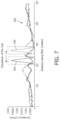
- FIG. 7 is a graph showing shape sensing data with a hub template and showing the hub template shifting with movement of a hub in accordance with the present principles
- FIG. 8 is a diagram showing a dynamic hub with a deformable mechanism for setting a position of a shape sensed flexible instrument to infer a position/orientation of a deployable device in accordance with one embodiment
- FIGS. 9 A and 9 B is a transparent side view showing a hub with a lever mechanism in an open position and a closed position to adjust a shape sensed flexible instrument in accordance with one embodiment
- FIGS. 10 A, 10 B, 10 C and 10 D are transparent side views with corresponding cross-sectional views showing a hub with a push button mechanism in an open position and a closed position to adjust a shape sensed flexible instrument in accordance with another embodiment
- FIG. 11 is a cross-sectional view showing a cam, cam follower and knob for adjusting a shape sensed instrument in accordance with another embodiment
- FIGS. 12 A, 12 B, 12 C and 12 D is a transparent side view showing a hub with a lever mechanism in an engaged position and in an unengaged position to adjust a shape sensed flexible instrument in accordance with another embodiment
- FIG. 13 is a transparent side view showing a hub with a biased lever mechanism in an engaged position and in an unengaged position to adjust a shape sensed flexible instrument in accordance with another embodiment
- FIGS. 14 A, 14 B and 14 C shows a progression of views of a biased hub being loaded on a guidewire in accordance with another embodiment
- FIG. 15 is a side view showing a compression hub in an open position and a closed position to adjust a shape sensed flexible instrument in accordance with another embodiment.
- a shape sensed guidewire for use in a lumen that also senses the position of any commercial over-the-wire device or component. If a catheter (or other deployable device) is employed over a shape sensed guidewire (or other flexible elongated device) then the guidewire shape also defines the catheter shape for the length over which the catheter overlaps the guidewire. To properly define the position of the catheter along the guidewire, a relationship between the catheter and the guidewire needs to be known. This can be done by using a hub device to cause the guidewire to take on a specific shape, curvature, or strain profile (shape profile) at a specific position along the catheter. A method to induce such a shape, curvature or strain profile is to employ the ‘hub’ with a known profile which can be stored as a template.
- the shape information from the sensed device can be used to infer information about the shape and position of the unsensed device.
- the registration needed may include a longitudinal translation between the two devices. This registration can be performed by using a known shape deformation of the sensed device at a specific location along the unsensed device.
- the shape deformation can be detected through curvature detection, axial strain (from heating or tensions), 2D or 3D shape matching, etc.
- hubs that use a shape deformation (as opposed to a strain deformation due to temperature, for example) the shape deformation will also define a plane.
- the same hub device can be used to track orientation of the device (e.g., roll about its longitudinal axis). Orientation of the hub at a proximal part of the device may map 1-to-1 to a therapeutic such as a balloon, valve, endograft, stent, etc. located in the distal portion.
- the present principles describe hub designs that can be used to create a template profile. These designs may include, e.g., a Luer lock hub, an over-catheter hub, a hemostatic valve hub, among others.
- a hub may be defined as a component that can create a shape or curvature deformation in a shape sensed device, such as a guidewire. Such a component should be able to work in a wide range of commercially available medical devices within a clinical environment.
- the hub design can be employed across multiple device designs. Multiple different versions of hub designs can be used for deforming the guidewire and performing longitudinal encoding.
- the over-the-wire device can be employed to display a model of a therapeutic such as a balloon, valve, endograft, stent, etc.
- a therapeutic such as a balloon, valve, endograft, stent, etc.
- EVAR endovascular aneurysm repair
- the position of the endograft needs to be known so that other catheters and endografts can be navigated with respect to an original endograft. This calls for significant amounts of fluoroscopy and contrast. If the endografts are not correctly positioned, a number of issues may arise.
- EVAR replaced open surgery as the most common technique for the repair of abdominal aortic aneurysms (AAA).
- AAA abdominal aortic aneurysms
- the procedure is usually carried out under x-ray fluoroscopy guidance and uses significant amounts of contrast to position and deploy the stent graft correctly.
- 50-100 mL of contrast dye is used during an EVAR procedure, which can result in acute renal failure in ⁇ 7% of cases.
- One complication from EVAR is endoleaks resulting from an insufficient seal of the stent graft to the aorta. Endoleaks involve incorrect flow around the stent (for example, flow around the stent at the proximal or distal attachment site, flow through the graft wall, retrograde flow from the branches, etc.).
- EVAR ischemia of the aortic side branches (such as the colonic, renal, and pelvic arteries). This can occur due to misplacement of the stent graft such that the stent partially or completely covers one of the side vessels, and this is associated with a lack of high-quality imaging technology as well as the learning curve of the endovascular team.
- aortic side branches such as the colonic, renal, and pelvic arteries.
- stent grafts are contained within a stent-deployment system that is used to navigate the stent to the correct part of the vasculature.
- the deployment systems tend to be relatively large and stiff endovascular devices. They typically involve a handle or set of knobs and dials at the proximal end to control the various steps around the stent deployment.
- the stent lies within the distal part of the device and is only released once the device has been navigated to the appropriate location.
- the stent completely deploys in one step, while in other cases the stent can be partially deployed to allow for correct positioning and orientation before the final deployment step firmly attaches the stent to the vasculature (typically through the retaining/sealing ring).
- the endovascular stent graft needs a sufficient amount of healthy vasculature where it can land its sealing ring. If this is not possible beneath the renal arteries, then the stent will cover those arteries, and needs to create some alternative way of maintaining flow to those vessels.
- a fenestrated stent e.g., a stent with windows for the side-branches
- FEVAR fenestrated endovascular aneurysm repair
- the stent has fenestrations that are lined up correctly with the side branches and additional stents are placed to connect the side vessels to the main stent.
- the stent Under x-ray guidance the stent can be visualized through x-ray visible markers that are located in key positions on the stent. In the fenestrated stent, the markers identify the locations of the fenestrations and can be used to orient the stent to appropriately align the fenestrations with the side vessels.
- devices and methods include registering a hub to a target node of an over-the-wire device and visualizing the over-the-wire device and a model at a target node in the over-the-wire device.
- This permits any commercial catheter, deployment system, sheath, or other such device to be navigated using a shape sensed guidewire.
- devices and methods make use of a proximal hub to determine orientation of a distal portion of a device such as a commercially available catheter, deployment system, or sheath that is fitted over a shape sensing guidewire.
- the hub may include a shape profile that deflects the guidewire passing through it into a known shape.
- That shape can be detected along the fiber to know the longitudinal registration between the guidewire and the over-the-wire device. Since the hub is coupled to the over-the-wire device, the hub shape can also be used to track the rotation or position applied to the proximal part of the over-the-wire device.
- the rotation of the hub can be measured by fitting a plane to the known shape profile inside the hub, and tracking the orientation of that plane over time.
- a model of a fenestrated endograft is rotated to better align the fenestrations on the endograft with an anatomical model.
- the rotation of the hub shape about itself is used to map the rotation of the endograft that is housed within a distal portion of the device. This allows any commercial catheter (manual or robotic), deployment system, sheath, or other such device to be navigated using a shape sensed guidewire. This can be applied to many applications such as vascular (catheters, sheaths, deployment systems, etc.), endoluminal (endoscopes), orthopedic (k-wires & screwdrivers) as well as non-medical applications.
- a deformable registration device utilizing Fiber-Optical RealShapeTM (FORSTM also known as “Optical Shape Sensing”, “Fiber Shape Sensing”, “Fiber Optical 3D Shape Sensing”, “Fiber Optic Shape Sensing and Localization” or the like) may be used.
- FORSTM Fiber-Optical RealShapeTM
- a Fiber-Optical RealShapeTM system is a commercial name for systems developed by Koninklijke Philips, N.V.
- FORSTM and FORSTM systems are not, however, limited to products and systems of Koninklijke Philips, N.V., but refer generally to fiber optic shape sensing and fiber optic shape sensing systems, fiber optic 3D shape sensing, fiber optic 3D shape sensing systems, fiber optic shape sensing and localization and similar technologies.
- the present invention will be described in terms of medical instruments; however, the teachings of the present invention are much broader and are applicable to any fiber optic instruments.
- the present principles are employed in tracking or analyzing complex biological or mechanical systems.
- the present principles are applicable to internal tracking procedures of biological systems and procedures in all areas of the body such as the lungs, gastro-intestinal tract, excretory organs, blood vessels, etc.
- the elements depicted in the FIGS. may be implemented in various combinations of hardware and software and provide functions which may be combined in a single element or multiple elements.
- processor or “controller” should not be construed to refer exclusively to hardware capable of executing software, and can implicitly include, without limitation, digital signal processor (“DSP”) hardware, read-only memory (“ROM”) for storing software, random access memory (“RAM”), non-volatile storage, etc.
- DSP digital signal processor
- ROM read-only memory
- RAM random access memory
- non-volatile storage etc.
- embodiments of the present invention can take the form of a computer program product accessible from a computer-usable or computer-readable storage medium providing program code for use by or in connection with a computer or any instruction execution system.
- a computer-usable or computer readable storage medium can be any apparatus that may include, store, communicate, propagate, or transport the program for use by or in connection with the instruction execution system, apparatus, or device.
- the medium can be an electronic, magnetic, optical, electromagnetic, infrared, or semiconductor system (or apparatus or device) or a propagation medium.
- Examples of a computer-readable medium include a semiconductor or solid state memory, magnetic tape, a removable computer diskette, a random access memory (RAM), a read-only memory (ROM), a rigid magnetic disk and an optical disk.
- Current examples of optical disks include compact disk—read only memory (CD-ROM), compact disk—read/write (CD-R/W), Blu-RayTM and DVD.
- any of the following “/”, “and/or”, and “at least one of”, for example, in the cases of “A/B”, “A and/or B” and “at least one of A and B”, is intended to encompass the selection of the first listed option (A) only, or the selection of the second listed option (B) only, or the selection of both options (A and B).
- such phrasing is intended to encompass the selection of the first listed option (A) only, or the selection of the second listed option (B) only, or the selection of the third listed option (C) only, or the selection of the first and the second listed options (A and B) only, or the selection of the first and third listed options (A and C) only, or the selection of the second and third listed options (B and C) only, or the selection of all three options (A and B and C).
- This may be extended, as readily apparent by one of ordinary skill in this and related arts, for as many items listed.
- System 100 may include a workstation 112 (or console) from which a procedure is supervised and/or managed.
- Workstation 112 preferably includes one or more processors 114 and memory 116 for storing programs and applications.
- Memory 116 may store an optical sensing module 122 configured to interpret optical feedback signals from a shape sensing device or system 104 (FORSTM).
- Optical sensing module 122 is configured to use the optical signal feedback (and any other feedback) to reconstruct deformations, deflections and other changes associated with shape sensed devices.
- a medical device 102 (alternatively “instrument”) comprises a lumen 103 , which receives a guidewire 108 or other elongated flexible instrument therein.
- the guidewire 108 is configured to receive the shape sensing system 104 therethrough.
- the medical device 102 may include a catheter, a sheath, a probe, an endoscope, a robot, an electrode, a filter device, a balloon device, a graft, a stent or other medical component having a lumen, etc.
- the medical device 102 is considered to be an over-the-wire device or component.
- the medical device 102 includes a hub 106 that may be configured within the medical device 102 , applied (connected/coupled) to the medical device 102 or configured to fit within the medical device 102 .
- the shape sensing system 104 includes one or more optical fibers which may be arranged in a set pattern or patterns.
- the optical fibers 126 connect to the workstation 112 through cabling.
- the cabling may include fiber optics, electrical connections, other instrumentation, etc., as needed.
- Shape sensing system 104 with fiber optics may be based on fiber optic Bragg grating sensors, Rayleigh scattering, or other types of scattering.
- Inherent backscatter in conventional optical fiber can be exploited, such as Raleigh, Raman, Brillouin or fluorescence scattering.
- One such approach is to use Rayleigh scatter in standard single-mode communications fiber. Rayleigh scatter occurs as a result of random fluctuations of the index of refraction in the fiber core. These random fluctuations can be modeled as a Bragg grating with a random variation of amplitude and phase along the grating length.
- a fiber optic Bragg grating (FBG) system may also be employed for shape sensing system 104 .
- FBG is a short segment of optical fiber that reflects particular wavelengths of light and transmits all others. This is achieved by adding a periodic variation of the refractive index in the fiber core, which generates a wavelength-specific dielectric mirror.
- a fiber Bragg grating can therefore be used as an inline optical filter to block certain wavelengths, or as a wavelength-specific reflector.
- Bragg wavelength is sensitive to strain as well as to temperature. This means that Bragg gratings can be used as sensing elements in fiber optical sensors.
- Incorporating three or more cores permits a three dimensional form of such a structure to be precisely determined. From the strain measurement, the curvature of the structure can be inferred at that position. From the multitude of measured positions, the total three-dimensional form is determined.
- a similar technique can be used for multiple single-core fibers configured in a known structure or geometry.
- workstation 112 is configured to receive feedback from the shape sensing system 104 and record accumulated position data as to where the shape sensing system 104 has been within a volume 130 .
- the shape sensing information within the space or volume 130 can be displayed on a display device 118 .
- Workstation 112 includes the display device 118 for viewing internal images of a subject (patient) or volume 130 and may include shape images 134 as an overlay on medical images 136 such as x-ray images, computed tomography (CT) images, magnetic resonance images (MRI), real-time internal video images or other images as collected by an imaging system 110 in advance or concurrently.
- Display device 118 may also permit a user to interact with the workstation 112 and its components and functions, or any other element within the system 100 . This is further facilitated by an interface 120 which may include a keyboard, mouse, a joystick, a haptic device, or any other peripheral or control to permit user feedback from and interaction with the workstation 112 .
- a registration device 144 is stored in memory 116 and is configured to register the hub 106 to a target node(s) 124 in the over-the-wire medical device 102 .
- the target node 124 may include any identifying features on the medical device 102 that can be employed as a reference for the hub 106 .
- the medical device 102 and the target node 124 are preferably visualized in an image or medical images 136 .
- a virtual model 146 of the over-the-wire medical device 102 may be rendered using the target node 124 as a reference to visualize in the over-the-wire medical device 102 .
- the hub 106 is registered to the target node 124 in the over-the-wire medical device 102 by attaching the hub 106 to a proximal portion of an over-the-wire medical device 102 to enable a registration (e.g., longitudinal) between the shape sensed guidewire 108 and the over-the-wire medical device 102 .
- the hub location may be mapped to other device nodes.
- Target nodes 124 are considered to be device features of interest to the clinician. Examples may include a device tip, a position of a fenestration, start and end points of a balloon, location of an ultrasound transducer, etc.
- the target node 124 may include a tip position of the medical device 102 .
- This target node 124 may be employed for positioning many devices and may be employed for safety reasons (e.g., making sure that the tip does not protrude too far into certain vessels that the tip of the device remains inside the vessel, etc.).
- the hub 106 is attached to the over-the-wire medical device 102 , it is not possible to correctly visualize the device in space until the mapping between the tip of the medical device 102 and the hub 106 is known.
- a length of the medical device 102 may be input to an image processing module 148 , which renders a position and dimension(s) of the devices using visualization software. This may be provided by scanning a barcode of the medical device 102 and looking up its properties in a database, the user entering a value directly or reading values from a device package, measuring by hand, etc.
- the medical device 102 may be recognized by the image processing module 148 using an x-ray image and automatically looking up the information from a database.
- the medical device 102 may be placed and attached to the hub 106 in an x-ray field of view (FOV) and have its length/dimension automatically detected from the resulting image.
- FOV x-ray field of view
- One or more x-ray projections can be employed, and this can work for all devices.
- automatic detection may be performed in other ways, e.g., to know the length, just align the guidewire tip with the tip of the device and click a button, or, loop the tip of the device back onto a known feature on the hub (a divot, for example) and click a button.
- hub 106 provides a straightforward attachment onto a wide range of commercial devices.
- the function of the guidewire 108 is preserved, e.g., for clinical manipulation such as translation and torqueing.
- the hub 106 provides an integrated solution for the transfer of data (e.g., hub templates, etc.).
- the hub 106 is employed to create shape deformation in the guidewire 108 that can be used for longitudinal registration.
- the hub 106 preferably can be retrofit to any commercial medical device ( 102 ) that runs over a guidewire 108 (or other elongated flexible shape sensed device).
- the medical device 102 may include a catheter, sheath, introducer, endograft deployment system, valve deployment system, transseptal needle, etc. These devices have a wide range of sizes, flexibility and profiles.
- a cylindrical Luer lock hub 206 deforms a guidewire 208 into a known shape profile 210 .
- the guidewire 208 includes a lumen for receiving a FORSTM system, and the guidewire 208 can pass through a lumen into a catheter 202 (medical device 102 ).
- Many devices include a male Luer lock component 220 at a proximal end of the guidewire lumen in the catheter 202 . This male Luer lock component 220 is used to flush the device with saline prior to use, or to flush with contrast during use.
- the hub 206 has a female Luer lock 222 on its distal portion which can mate onto the proximal end of the catheter 202 . This effectively extends the guidewire lumen, and the extended portion is employed to create a known curvature change.
- An additional advantage of using a Luer lock system 200 is that clinicians are already familiar with how to use it, and it would not hinder workflow.
- a secondary attachment or lock may be employed that can lock the hub 206 onto the catheter 202 so that during torqueing the hub does not decouple from the catheter 202 .
- the attachment (secondary lock 232 in FIG. 3 ) will catch the catheter 202 lock for torqueing in one direction, but will permit it to loosen in the other direction.
- a schematic diagram shows a shape sensed guidewire 208 , a catheter 202 and a hub 206 , which deforms the guidewire shape attached to the catheter 202 using the Luer lock system 200 .
- Other features of the hub 206 may include a replicated female Luer 222 at the proximal portion of the hub 206 to permit other devices to mate thereon (as they would normally mate directly to a device).
- a hemostatic valve 230 or other device may be mounted to the female Luer lock 222 of the hub 206 .
- a secondary lock 232 may be provided to capture the hub 206 and hemostatic valve 230 and prevent rotation or unwanted release between the devices.
- the secondary lock 232 may be split-half and may include securing features, like snaps, screws, fasteners, etc.
- an over-catheter hub 306 suitable for use with smaller catheters includes an ‘over-catheter’ design. This may include split-half or clamshell portions 308 that a catheter 302 is placed into and then the over-catheter hub 306 is closed around the catheter 302 . Alternatively, the catheter 302 may be passed through a lumen 314 in the over-catheter hub 306 .
- the over-catheter design is desirable because it means that a guidewire (not shown) only passes through the catheter lumen.
- the over-catheter hub 306 does not add any additional lumen or components that interact with the guidewire.
- the lumen of the device (catheter 302 ) needs to be flexible enough to pass through the shape deformation in the over-catheter hub 306 .
- This may be suitable for thinner, flexible devices like navigation catheters but may not be suitable for larger, stiffer devices, e.g., endograft deployment systems.
- instance 300 shows the over-catheter hub 306 with the clam-shell design in an open position showing a curved path for the lumen 314 in part of the clamshell portions 308 .
- Instance 310 shows the over-catheter hub 306 clamped over the catheter 302 .
- the catheter 302 includes a guidewire therein (not shown) and the guidewire includes a FORSTM system therein.
- a hemostatic valve ( 230 , FIG. 3 ) may be employed with a mating male/female connection for a catheter. The valve is opened fully and a hub's distal portion may be inserted into the valve. Then, an outer component or secondary lock ( 232 , FIG. 3 ) of the hub fastens around the valve to secure the hub in place.
- Multiple hub designs can be considered with varying paths for the guidewire. Examples of designs in addition to those already described are illustrated in FIG. 5 .
- hub designs 506 a , 506 b , 506 c may include many shapes and sizes. Different designs may include different profiles for guiding a FORSTM system within a guidewire.
- An orientation feature 502 such as, a color marker, divot, or raised ridge feature that identifies the orientation of the device may be provided. This can enable the user to use the hub for rotational alignment or other registration functions.
- the hub 506 may include ergonomic features 504 to facilitate torqueing of a medical device 102 ( FIG. 1 ). This could include a winged shape profile, a ridged profile, etc. to give users a better grip.
- a low-friction lumen or path (PTFE coated, hydrophilic coated, etc.) may be provided to minimize the effect on the guidewire.
- the hub 600 includes a hub body 606 , which may include a solid design, a split half design, etc.
- the hub body 606 includes an attachment feature 616 as described above, such as a Luer lock, etc.
- the hub body 606 provides a deformable path that includes a mechanism 608 for displacing the flexible instrument to form a profile in the hub body in the deformable path to impart a hub template, when the mechanism is in a first position, to distinguish a portion of the elongated flexible instrument within the hub in shape sensing data.
- the hub body 606 may include a biasing component (mechanism 608 ) such as a spring returned button 609 to induce the shape deformation when needed.
- a biasing component such as a spring returned button 609 to induce the shape deformation when needed.
- the hub body 606 may also include a permanent shaped path. Hub body 606 may include any combination of path changes (e.g., permanent, heated, reversible) to form a shape profile 630 .
- the shape profile 630 results in a set hub profile in shape sensed data.
- the user initiates registration in the software (registration device 144 , FIG. 1 ), and the length of the device is computed using the known relationship between the template position and the registration feature 612 .
- the hub body 606 includes a proximal Luer lock or other attachment feature 616 that is free to rotate and pivot to allow improved usability.
- the attachment feature 616 may include torque stops, locks or other features 618 to prevent removal if twisting in one direction but permit removal in the other direction.
- the hub body 606 may include radio-opaque or other such features 624 to permit for registration of the hub in another imaging modality (e.g., fluoroscopy/x-ray, MRI, CT, ultrasound, etc.). This could also include a radio-opaque lumen to detect a hub template.
- a locking mechanism 620 may be included to capture the shape sensed guidewire 622 to the hub body 606 so that they no longer translate with respect to each other.
- the locking mechanism 620 may include a spring loaded pin, a screw, a latch, a snap, etc.
- the hub body 606 may be identified using an identifier 626 , which may include a code, serial number, radiofrequency identifier (RFID) tag, microchip, etc. in the hub body 606 to identify its hub template from a database or other reference.
- the hub body 606 may identify itself through the use of a unique template that may be stored in the database.
- the hubs in accordance with the present principles can operate with a large variety of devices.
- hubs may be employed with endograft deployment devices, etc.
- Other devices that may be employed with the hubs can include sheaths, introducers, mitral clip delivery systems, mitral valve delivery systems, aortic valve delivery systems, therapeutic catheters, balloon catheters, ablation catheters, imaging catheters (intravascular ultrasound (IVUS), optical coherence tomography (OCT), etc.), infusion catheters, endoscopes, needles, etc.
- IVUS intravascular ultrasound
- OCT optical coherence tomography
- the over-the-wire devices are described as being placed over shape sensed guidewires, the present principles are not limited to a guidewire as the shape sensed device.
- any flexible elongated device may be employed and any tool with a shape sensed fiber within it may be employed to infer a shape of another tool.
- a retrofit hub has been described, the hub could also be fully integrated into the design of the catheter or medical device (over-the wire device). All of the features remain the same, with the exception of the attachment mechanism that attaches to the medical device.
- a curvature plot or graph 702 showing curvature (1/mm) versus distance along a fiber (nodes) is shown.
- the plot or graph 702 shows a hub that has been translated from left to right as indicated by arrow “B” in two time period plots.
- a hub template 704 of the hub is shown being translated.
- the hub template 704 of the hub curvature (or other shape profile) needs to be used to match against the guidewire curvature (or other shape profile).
- This hub template 704 can be derived in plurality of ways. These may include being selected by a user from a database of stored templates by entering an identifier that is written on the hub or hub packaging.
- the hub template 704 may be identified using a radiofrequency identifier (RFID) tag in the hub to identify its template from a database.
- RFID radiofrequency identifier
- the hub template 704 may be identified using a microchip in the hub that stores the hub template 704 completely.
- a search algorithm may be employed that looks at shape sensed data along the shape sensed device and identifies the hub template 704 from within the shape data. This could be done fully automatically (e.g., a search algorithm can look along a straight guidewire and find the most likely hub candidate), with user input to confirm the automatically detected hub, or to limit the search range to find the hub, or to position the hub in two different locations (to help the algorithm find the thing that changed). This could also be done with full user input to select the hub from the shape, with x-ray (or other imaging such as optical, ultrasound, MRI, etc.) to image the hub and then detect the path, etc. The full template can be detected, or a pattern-matching algorithm could match the x-ray view of the hub to potential template matches in a database.
- the hub template 704 may take on any usable shape including 2D or 3D profiles.
- the hub template 704 needs to be distinguishable from other shape sensing data.
- the use of an attachable hub is provided to cause the shape deformation of a shape sensed guidewire or tool through the visual shape representation of a device that is not enabled with shape sensing but that is being used with the shape sensed tool. This permits any commercial catheter (manual or robotic), deployment system, sheath, or other such device to be navigated using a shape sensed guidewire (or other tool).
- vascular catheters, sheaths, deployment systems, etc.
- endoluminal endoluminal
- orthopedic k-wires and screwdrivers
- a shape-sensed guidewire 802 is included in a catheter 804 with a hub 806 .
- the hub 806 includes a deformable mechanism 808 (or switch) to deform a guidewire shape attached to the catheter 804 via a Luer lock or other device. If the catheter 804 (or other device) is employed over the shape-sensed guidewire 802 , the guidewire shape also defines the catheter shape for the length over which the catheter 804 overlaps the shape-sensed guidewire 802 . To properly define the position of the catheter 804 , a relationship between the catheter 804 and the shape-sensed guidewire 802 needs to be known.
- shape-sensed guidewire 802 with a FORSTM fiber or fibers 810 take on a specific shape, curvature, or strain profile at a specific position along the catheter 804 .
- One way to induce such a shape, curvature or strain profile is to use the hub 806 .
- a dynamic version of the hub 806 can be employed that can selectively turn on and off its effect on an optical fiber employed in the shape-sensed guidewire 802 .
- the hub 806 can be employed with a back-loadable shape-sensed guidewire 802 .
- the hub 806 is employed to create a shape deformation in the shape-sensed guidewire 802 that can be used for longitudinal registration.
- the hub 806 has a feature to enable turning on/off a curvature template.
- the hub 806 should be simple to switch between on/off states by an operator (e.g., while wearing surgical gloves, etc.). In addition, when the hub 806 is turned ‘on’, the hub 806 needs to create a reproducible change in the shape sensed guidewire 802 .
- the hub 806 is selectively interactable with the shape-sensed guidewire 802 .
- the hub 806 may introduce additional friction that could impact manipulation of the shape-sensed guidewire 802 .
- the user may want to have the hub 806 in a disabled state during gross manipulations and then turn on the hub 806 for finer device manipulations.
- there may be a region at a proximal end of the shape-sensed guidewire 802 that is completely rigid (due to optical components). If the hub 806 employs a curve or non-straight shape template then the hub 806 may be disabled when the stiff proximal section of the shape-sensed guidewire 802 passes through the hub 806 .
- the hub 806 is used to create shape deformation in the shape-sensed guidewire 802 be deflecting or pressing the mechanism 808 to provide a change in the fiber 810 to be used for longitudinal registration.
- the hub 806 has a feature or mechanism 808 to enable turning on/off a curvature template.
- the hub 806 is easily switched between on/off states by the operator (e.g., while wearing surgical gloves) or may be controlled remotely to create a reproducible template change in the shape sensed guidewire 802 .
- a lever or latching lever hub 912 is shown in an open position 900 and a closed position 901 .
- the latching lever hub 912 includes a hinged lever 904 having an engagement portion 906 .
- the latching lever hub 912 includes Luer lock connections 910 and 908 (or other standard connections) for engaging or connecting the hub to a catheter or other device.
- a shape sensing fiber shape-sensing guidewire
- the lever 904 is open, in open position 900 , the fiber is disposed on a straight path 914 through the latching lever hub 912 .
- the fiber When the lever 904 is in a closed position, the fiber is disposed on a curved path 902 through the latching lever hub 912 .
- the hinged lever 904 can now be moved in the direction of arrow “B” so that the engagement portion engages and moves the fiber to a curved path 916 as shown in the closed position 901 .
- a curved template is provided with curved path 916 while also allowing for the straight path 914 as a default.
- the curved path 916 may be the default in some embodiments.
- a latch or latching mechanism 918 e.g., a clip, hook, etc.
- a release 920 may also be employed that can be depressed to release the hinged lever 904 from the closed position 901 .
- Other latching mechanisms or release mechanisms may also be employed.
- a pushbutton or latching pushbutton hub 1008 is shown in an open position 1000 and a closed position 1001 .
- the pushbutton or latching push bottom hub 1008 includes a push button 1002 having an engagement portion 1012 shown in a cross-section 1010 of the push button 1002 .
- the pushbutton or latching push bottom hub 1008 includes Luer lock connections 910 and 908 for engaging or connecting the pushbutton or latching push bottom hub 1008 to a catheter or other device.
- a shape sensing fiber shape-sensing guidewire
- the fiber is disposed on a straight path 1004 through the pushbutton or latching push bottom hub 1008 .
- the push button 1002 can now be moved in the direction of arrow “C” so that the engagement portion engages and moves the fiber to a curved path 1006 as shown in the closed position 1001 and a cross-section 1011 of the closed position.
- a curved template is provided with curved path 1006 while also allowing for the straight path 1004 as a default.
- the curved path 1006 may be the default in some embodiments.
- a latch or latching mechanism 1114 e.g., a clip, hook, etc.
- a release may also be employed that can be depressed to release the push button 1002 from the closed position 1001 .
- Other latching mechanisms or release mechanisms may also be employed.
- Springs or a biasing device may be employed to force the push button 1002 into its default position, e.g., to permit the guidewire to pass through unimpeded.
- the pushbutton or latching push bottom hub 1008 can be sealed at all times.
- cam 1102 and a cam follower mechanism 1104 to introduce a template are illustratively shown in accordance with another embodiment.
- a knob 1108 is turned in the direction of arrow “D”
- the cam follower mechanism 1104 is forced down in the direction of arrow “E” onto a guidewire 1106 .
- the cam follower mechanism 1104 follows the contour of a surface of the cam 1102 .
- the template is applied directly to the guidewire 1106 as a rotational input using the cam 1102 .
- the knob 1108 can be added to any hub. As the knob 1108 is turned, the cam 1102 rotates and moves the cam follower mechanism 1104 , which in turn forces the template curvature onto the guidewire 1106 .
- This permits variable templates and may impart different levels of curvature, e.g., the more the knob 1108 is turned, the more curvature is applied to the guidewire 1106 .
- a barrel cam may be employed with the cam follower attached to a bent lever. As the barrel cam is rotated, the lever arm moves up and down, thereby introducing the template.
- One advantage of the cam embodiments includes providing a progressive amount of curvature that can be applied depending on the amount of rotation.
- Stiffer guidewires may take on less curvature in a body, and may also be more sensitive to curvature in the hub (thereby inducing more friction during navigation). Different guidewires could have different pre-set rotations corresponding to differing amounts of curvature, depending on their stiffness.
- a lever 1204 may be employed to deflect a fiber or guidewire 1206 in a hub 1202 .
- the lever 1204 In position 1200 , the lever 1204 is in a neutral state and is not engaged with fiber or guidewire 1206 .
- the lever 1204 In position 1201 , the lever 1204 is rotated about a pivot point to engage the fiber or guidewire 1206 .
- the lever 1204 can be employed with the fiber or guidewire 1206 to induce a deformation/offset at a point in the hub 1202 in position 1201 . This reduces friction because only a single point of contact is made with the fiber or guidewire 1206 .
- the lever 1204 may be employed to deflect the fiber or guidewire 1206 in the hub 1202 using a biasing member or spring 1212 .
- the lever 1204 In position 1220 , the lever 1204 is in a retracted state maintained by the spring 1212 and is not engaged with fiber or guidewire 1206 .
- the lever 1204 In position 1221 , the lever 1204 is rotated about a pivot point to engage the fiber or guidewire 1206 .
- the lever 1204 can be employed with the fiber or guidewire 1206 to induce a deformation/offset at a point in the hub 1202 in position 1221 . This reduces friction because only a single point of contact is made with the fiber or guidewire 1206 .
- the bias of spring 1212 causes the lever to return to position 1220 when released.
- the lever 1204 can be secured in either state using mechanical elements.
- the guidewire may be disposed in a tube (fiber or guidewire 1206 ) that deflects the guidewire therein when engaged with the lever 1204 (or any other element as described herein).
- the tube could protect the guidewire and/or further reduce friction.
- the spring 1212 could be used to create a preferred state. For example, that the hub 1202 may have as a default, the lever 1204 applied, and the user depresses the lever 1204 to remove the curvature.
- a hub 1408 is shown in three positions 1402 , 1404 , and 1406 along a guidewire 1414 .
- the hub 1408 includes an engagement portion 1416 having a biasing device 1418 , such as, e.g., a spring or other mechanism for applying a force against a catheter 1410 or other device.
- the guidewire 1414 includes a stiff proximal portion 1412 that leads the guidewire 1414 and will be passed first into the catheter 1410 and the hub 1408 in the direction of arrow “F”.
- the biasing device 1418 pushes a curved part onto the catheter 1410 to create a desired curve.
- the stiff proximal portion 1412 of the guidewire 1414 enters the hub 1408 , the stiff proximal portion 1412 enters the hub 1408 and displaces the biasing device 1418 to permit passage of the stiff proximal portion 1412 .
- the stiff proximal portion 1412 pushes the engagement portion 1416 (curved portion) inside the hub to straighten it when the hub 1408 is moved in the direction of arrow “G”.
- the biasing device 1418 pushes the catheter 1410 and the guidewire 1414 into a desired curve or template.
- the biasing device 1418 may include a spring, a manual force, etc. and may be applied at different positions in the hub 1408 .
- a compressing hub 1502 is depicted in accordance with another embodiment.
- the compressing hub 1502 includes an open position 1520 where a shape-enabled guidewire 1510 or FORSTM fiber is inserted through open ends 1522 .
- the shape-enabled guidewire 1510 may be placed in a protective tube.
- a guiding feature 1512 is located adjacent to the tube/guidewire/fiber 1510 .
- the compressing hub 1502 may include separable portions 1504 and 1506 that are separated in the open position 1520 .
- the separable portions 1504 and 1506 may be guided using guides 1508 or other mechanical features.
- the shape-enabled guidewire 1510 is compressed and forms a curved shape due to the path-length change.
- the guiding feature 1512 may be bowed to ensure a reproducible template.
- optical sensing module 122 may be employed to detect when the hub template is present by looking for a match of a shape where the match is computed to be better than a threshold value.
- the visualization of the device would only happen once the hub was ‘on’ and the template match was detected.
- the hub could have an additional feature to give input as to its on/off state. This may include an electronic signal, a mechanical switch, an RF signal or any other signal or assisting method known in the art. For example, when the hub has a lever engaged, halves closed, pressure applied, a signal is generated and the visualization of the shape is checked for by the optical sensing module 122 ( FIG. 1 ).
- the guidewires described included shape sensing fiber or fibers. It should be understood that the present principles are not limited to guidewires as the shape sensed devices. Any tool with a shape sensed fiber associated therewith may be employed to infer a shape of another tool.
- the hubs/dynamic hubs described herein may include retrofit hubs that slide over devices to provide a template.
- the hub may also be fully integrated into a catheter (or medical device). The features described remain the same for fully integrated hubs, but with attachment mechanisms adjusted depending on the device having the hub thereon.
- the shapes depicted in some of the embodiments show a simple curve for illustrative purposes. It should be understood that the curve(s) may be more complex having multiple inflections, different cusps or arcuate shapes, multiple shapes, etc. to provide the templates for device or position identification.
- the hubs and dynamic hubs described herein may be employed with any commercial catheter (manual or robotic), deployment system, sheath, or other such device to be navigated using a shape sensed guidewire or other device for any applications such as, e.g., vascular (catheters, sheaths, deployment systems, etc.), endoluminal (endoscopes), orthopedic (k-wires and screwdrivers) as well as non-medical applications.
- vascular catheter, sheaths, deployment systems, etc.
- endoluminal endoluminal
- orthopedic k-wires and screwdrivers
Abstract
Description
-
- a) the word “comprising” does not exclude the presence of other elements or acts than those listed in a given claim;
- b) the word “a” or “an” preceding an element does not exclude the presence of a plurality of such elements;
- c) any reference signs in the claims do not limit their scope;
- d) several “means” may be represented by the same item or hardware or software implemented structure or function; and
- e) no specific sequence of acts is intended to be required unless specifically indicated.
Claims (13)
Priority Applications (1)
| Application Number | Priority Date | Filing Date | Title |
|---|---|---|---|
| US15/763,143 US11690975B2 (en) | 2015-10-02 | 2016-10-02 | Hub for device navigation with optical shape sensed guidewire |
Applications Claiming Priority (4)
| Application Number | Priority Date | Filing Date | Title |
|---|---|---|---|
| US201562236172P | 2015-10-02 | 2015-10-02 | |
| US201662349298P | 2016-06-13 | 2016-06-13 | |
| PCT/EP2016/073529 WO2017055620A1 (en) | 2015-10-02 | 2016-10-02 | Hub for device navigation with optical shape sensed guidewire |
| US15/763,143 US11690975B2 (en) | 2015-10-02 | 2016-10-02 | Hub for device navigation with optical shape sensed guidewire |
Publications (2)
| Publication Number | Publication Date |
|---|---|
| US20180279909A1 US20180279909A1 (en) | 2018-10-04 |
| US11690975B2 true US11690975B2 (en) | 2023-07-04 |
Family
ID=57133141
Family Applications (1)
| Application Number | Title | Priority Date | Filing Date |
|---|---|---|---|
| US15/763,143 Active 2040-09-25 US11690975B2 (en) | 2015-10-02 | 2016-10-02 | Hub for device navigation with optical shape sensed guidewire |
Country Status (5)
| Country | Link |
|---|---|
| US (1) | US11690975B2 (en) |
| EP (1) | EP3355780A1 (en) |
| JP (1) | JP7171432B2 (en) |
| CN (1) | CN108135530B (en) |
| WO (1) | WO2017055620A1 (en) |
Families Citing this family (15)
| Publication number | Priority date | Publication date | Assignee | Title |
|---|---|---|---|---|
| US11690975B2 (en) * | 2015-10-02 | 2023-07-04 | Koninklijke Philips N.V. | Hub for device navigation with optical shape sensed guidewire |
| US11547489B2 (en) | 2016-11-28 | 2023-01-10 | Koninklijke Philips N.V. | Shape sensing of multiple over-the-wire devices |
| CN110049741B (en) | 2016-12-05 | 2023-07-25 | 皇家飞利浦有限公司 | System and method for determining a length of a non-shape sensing interventional device using a shape sensing guidewire |
| WO2018127522A1 (en) | 2017-01-03 | 2018-07-12 | Koninklijke Philips N.V. | Medical navigation system using shape-sensing device and method of operation thereof |
| US10765836B1 (en) * | 2019-03-28 | 2020-09-08 | Horizon Patents, Llc. | Electronic guidewire detector for catheter insertion |
| CA3150788A1 (en) | 2019-08-12 | 2021-02-18 | Bard Access Systems, Inc. | Shape-sensing systems and methods for medical devices |
| CN214804697U (en) | 2019-11-25 | 2021-11-23 | 巴德阿克塞斯系统股份有限公司 | Optical tip tracking system |
| US20230060639A1 (en) * | 2020-02-12 | 2023-03-02 | Board Of Regents Of The University Of Texas System | Microrobotic systems and methods for endovascular interventions |
| EP4171423A1 (en) | 2020-06-26 | 2023-05-03 | Bard Access Systems, Inc. | Malposition detection system |
| WO2022005870A1 (en) | 2020-06-29 | 2022-01-06 | Bard Access Systems, Inc. | Automatic dimensional frame reference for fiber optic |
| CN114052658A (en) | 2020-08-03 | 2022-02-18 | 巴德阿克塞斯系统股份有限公司 | Bragg grating optical fiber fluctuation sensing and monitoring system |
| WO2022048984A1 (en) | 2020-09-02 | 2022-03-10 | Koninklijke Philips N.V. | Medical intervention control based on device type identification |
| EP4154810A1 (en) | 2021-09-28 | 2023-03-29 | Koninklijke Philips N.V. | System and device control using shape clustering |
| WO2023280732A1 (en) | 2021-07-08 | 2023-01-12 | Koninklijke Philips N.V. | System and device control using shape clustering |
| CN116019552A (en) * | 2021-10-25 | 2023-04-28 | 巴德阿克塞斯系统股份有限公司 | Reference plane for medical device placement |
Citations (41)
| Publication number | Priority date | Publication date | Assignee | Title |
|---|---|---|---|---|
| US136309A (en) * | 1873-02-25 | Improvement in hose-nozzles | ||
| US2366424A (en) * | 1944-03-20 | 1945-01-02 | Baxter Don Inc | Tubing and needle holder |
| US3822052A (en) * | 1973-04-02 | 1974-07-02 | Illinois Tool Works | Shut off clamp |
| US4477725A (en) * | 1981-08-27 | 1984-10-16 | Trw Inc. | Microbending of optical fibers for remote force measurement |
| US4643389A (en) * | 1984-12-27 | 1987-02-17 | American Hospital Supply Corporation | Tubing occlusion clip |
| US5195162A (en) * | 1987-12-16 | 1993-03-16 | General Motors Corporation | Planar polymer light guide methods and apparatus |
| US5258614A (en) * | 1991-05-13 | 1993-11-02 | The Babcock & Wilcox Company | Optical fiber loop temperature sensor |
| WO1998040774A1 (en) * | 1997-03-10 | 1998-09-17 | Minnesota Mining And Manufacturing Company | Fiber optic connector with a fibre bent to an s-shape |
| US5818982A (en) * | 1996-04-01 | 1998-10-06 | Voss; Karl Friedrich | Fiber optic sensor based upon buckling of a freely suspended length of fiber |
| WO2001033165A1 (en) * | 1999-10-29 | 2001-05-10 | Advanced Sensor Technology, Llc | Optical fiber navigation system |
| US6429421B1 (en) * | 2000-01-21 | 2002-08-06 | Luna Innovations, Inc. | Flexible fiber optic microbend device, with interlocking flexible fibers, sensors, and method use |
| US6592544B1 (en) * | 1999-11-24 | 2003-07-15 | Edwards Lifesciences Corporation | Vascular access devices having hemostatic safety valve |
| US20040163809A1 (en) * | 2003-02-24 | 2004-08-26 | Mayeu Christopher W. | Method and system for determining and controlling position of valve |
| US20050025647A1 (en) * | 2003-07-28 | 2005-02-03 | Ortega Victor J. | Quick loading peristaltic pump |
| US20050063662A1 (en) * | 2003-09-23 | 2005-03-24 | To 3M Innovative Properties Company | Device for gripping optical fibers |
| US6983096B2 (en) * | 2003-04-15 | 2006-01-03 | Intel Corporation | Attenuation of cladding modes in optical fibers |
| US20060015074A1 (en) * | 2002-11-04 | 2006-01-19 | Lynn Lawrence A | Catheter flushing fluid lock system and method |
| US20070299423A1 (en) * | 2006-06-26 | 2007-12-27 | Boston Scientific Scimed, Inc. | Wire stabilization |
| US20080147001A1 (en) | 2002-03-22 | 2008-06-19 | Laila Al-Marashi | Rapid-exchange balloon catheter shaft and method |
| US20090137952A1 (en) * | 2007-08-14 | 2009-05-28 | Ramamurthy Bhaskar S | Robotic instrument systems and methods utilizing optical fiber sensor |
| US20100202733A1 (en) * | 2007-09-14 | 2010-08-12 | Werner Herden | Diode laser having a device for beam forming |
| US20110113852A1 (en) * | 2009-11-13 | 2011-05-19 | Intuitive Surgical, Inc. | Optical fiber shape sensor calibration |
| US20110202069A1 (en) * | 2010-02-12 | 2011-08-18 | Prisco Giuseppe M | Method and system for absolute three-dimensional measurements using a twist-insensitive shape sensor |
| US20120289777A1 (en) * | 2011-05-13 | 2012-11-15 | Intuitive Surgical Operations, Inc. | Medical system providing dynamic registration of a model of an anatomical structure for image-guided surgery |
| US20130028554A1 (en) * | 2011-07-29 | 2013-01-31 | Hansen Medical, Inc. | Apparatus and methods for fiber integration and registration |
| WO2013024418A1 (en) * | 2011-08-16 | 2013-02-21 | Koninklijke Philips Electronics N.V. | Curved multi-planar reconstruction using fiber optic shape data |
| US20130276557A1 (en) * | 2009-11-13 | 2013-10-24 | Intuitive Surgical Operations, Inc. | Method and system to sense relative partial-pose information using a shape sensor |
| US20140060655A1 (en) * | 2012-08-30 | 2014-03-06 | C. R. Bard, Inc. | Tubing Clamp |
| WO2014053934A1 (en) * | 2012-10-01 | 2014-04-10 | Koninklijke Philips N.V. | System and method for registering shape sensing with imaging using an optimal plane |
| JP2014124302A (en) * | 2012-12-26 | 2014-07-07 | Terumo Corp | Catheter |
| US20140275997A1 (en) * | 2013-03-15 | 2014-09-18 | Intuitive Surgical Operations, Inc. | Shape sensor systems for tracking interventional instruments and mehods of use |
| WO2014191871A1 (en) | 2013-05-31 | 2014-12-04 | Koninklijke Philips N.V. | Optical shape sensing device calibration, characterization and failure detection |
| US20150031987A1 (en) * | 2013-07-24 | 2015-01-29 | Cook Medical Technologies Llc | Locating device |
| US20160213432A1 (en) * | 2013-10-02 | 2016-07-28 | Koninklijke Philips N.V. | Hub design and methods for optical shape sensing registration |
| US20170215973A1 (en) * | 2014-09-30 | 2017-08-03 | Koninklijke Philips N.V. | Triggering with optical shape sensing fiber |
| US20180014886A1 (en) * | 2015-01-22 | 2018-01-18 | Koninklijke Philips N.V. | Device visualization through optical shape sensing of a guidewire |
| US20180279909A1 (en) * | 2015-10-02 | 2018-10-04 | Koninklijke Philips N.V. | Hub for device navigation with optical shape sensed guidewire |
| US20190000562A1 (en) * | 2015-12-29 | 2019-01-03 | Koninklijke Philips N.V. | Registration system for medical navigation and method of operation thereof |
| US20190167357A1 (en) * | 2013-09-30 | 2019-06-06 | Koninklijke Philips N.V. | Docketing device for optical shape sensing launch fixtures |
| US10492871B2 (en) * | 2015-05-01 | 2019-12-03 | Intuitive Surgical Operations, Inc. | Fiber management in medical instrument backend |
| US10639007B2 (en) * | 2014-12-02 | 2020-05-05 | Koninklijke Philips N.V. | Automatic tracking and registration of ultrasound probe using optical shape sensing without tip fixation |
Family Cites Families (24)
| Publication number | Priority date | Publication date | Assignee | Title |
|---|---|---|---|---|
| EP1628700B1 (en) * | 2003-05-28 | 2011-12-21 | C.R. Bard, Inc. | High pressure catheter and methods for manufacturing the same |
| US7621927B2 (en) * | 2005-03-28 | 2009-11-24 | Ethicon Endo-Surgery, Inc. | Medical instrument with a mechanical coupling |
| WO2007025081A2 (en) * | 2005-08-24 | 2007-03-01 | Traxtal Inc. | System, method and devices for navigated flexible endoscopy |
| EP2671520A3 (en) * | 2006-02-06 | 2013-12-25 | ConforMIS, Inc. | Patient selectable joint arthroplasty devices and surgical tools |
| US20080097296A1 (en) * | 2006-08-16 | 2008-04-24 | Boston Scientific Scimed, Inc. | Removable hub assembly for medical device |
| US7734328B2 (en) * | 2006-12-21 | 2010-06-08 | General Electric Company | System and method to enhance visualization of an object in a vascular vessel |
| US20080294145A1 (en) * | 2007-05-25 | 2008-11-27 | Galt Medical Corporation | Catheter hub with flushable lumen and guidewire |
| WO2011080606A1 (en) * | 2009-12-28 | 2011-07-07 | Koninklijke Philips Electronics N.V. | Method and apparatus for brachytherapy featuring tracking via shape-sensing |
| WO2011159600A2 (en) * | 2010-06-13 | 2011-12-22 | Angiometrix Corporation | Diagnostic kit and method for measuring balloon dimension in vivo |
| US8460236B2 (en) * | 2010-06-24 | 2013-06-11 | Hansen Medical, Inc. | Fiber optic instrument sensing system |
| BR112013004528A2 (en) * | 2010-09-01 | 2016-06-07 | Koninkl Philips Electronics Nv | optical guidewire system and method for advancing a catheter to a target region relative to a distal end of an optical guidewire |
| US8764683B2 (en) * | 2010-12-29 | 2014-07-01 | Mediguide Ltd. | Medical device guidewire with a position sensor |
| WO2012100211A2 (en) * | 2011-01-20 | 2012-07-26 | Hansen Medical, Inc. | System and method for endoluminal and transluminal therapy |
| EP2667815B1 (en) * | 2011-01-27 | 2018-11-14 | Koninklijke Philips N.V. | Integration of fiber optic shape sensing within an nterventional environment |
| WO2012101551A1 (en) * | 2011-01-27 | 2012-08-02 | Koninklijke Philips Electronics N.V. | Templates for optical shape sensing calibration during clinical use |
| CN103492833B (en) * | 2011-02-18 | 2016-12-28 | 德普伊新特斯产品有限责任公司 | There is the instrument of integrated Navigation And Guidance system and relevant device and method |
| EP2508907A1 (en) * | 2011-04-07 | 2012-10-10 | Koninklijke Philips Electronics N.V. | Magnetic resonance guidance of a shaft to a target zone |
| EP2744409A1 (en) * | 2011-10-20 | 2014-06-25 | Koninklijke Philips N.V. | Shape sensing devices for real-time mechanical function assessment of an internal organ |
| JP6290099B2 (en) * | 2012-02-03 | 2018-03-07 | インテュイティブ サージカル オペレーションズ, インコーポレイテッド | Steerable flexible needle with implantable shape sensing function |
| WO2013168052A1 (en) * | 2012-05-09 | 2013-11-14 | Koninklijke Philips N.V. | System and method for stabilizing optical shape sensing |
| JP6246213B2 (en) * | 2012-10-01 | 2017-12-13 | コーニンクレッカ フィリップス エヌ ヴェKoninklijke Philips N.V. | Alignment system, method and computer program |
| CN105593731B (en) * | 2013-09-30 | 2017-12-05 | 皇家飞利浦有限公司 | Starting fixator for optic shape sensing |
| JP6693869B2 (en) * | 2013-10-02 | 2020-05-13 | コーニンクレッカ フィリップス エヌ ヴェKoninklijke Philips N.V. | Device tracking using longitudinal encoding |
| CN106061417B (en) * | 2014-02-27 | 2020-04-07 | 皇家飞利浦有限公司 | Registration device for interventional procedures |
-
2016
- 2016-10-02 US US15/763,143 patent/US11690975B2/en active Active
- 2016-10-02 EP EP16781315.3A patent/EP3355780A1/en active Pending
- 2016-10-02 CN CN201680057469.6A patent/CN108135530B/en active Active
- 2016-10-02 WO PCT/EP2016/073529 patent/WO2017055620A1/en active Application Filing
- 2016-10-02 JP JP2018516183A patent/JP7171432B2/en active Active
Patent Citations (42)
| Publication number | Priority date | Publication date | Assignee | Title |
|---|---|---|---|---|
| US136309A (en) * | 1873-02-25 | Improvement in hose-nozzles | ||
| US2366424A (en) * | 1944-03-20 | 1945-01-02 | Baxter Don Inc | Tubing and needle holder |
| US3822052A (en) * | 1973-04-02 | 1974-07-02 | Illinois Tool Works | Shut off clamp |
| US4477725A (en) * | 1981-08-27 | 1984-10-16 | Trw Inc. | Microbending of optical fibers for remote force measurement |
| US4643389A (en) * | 1984-12-27 | 1987-02-17 | American Hospital Supply Corporation | Tubing occlusion clip |
| US5195162A (en) * | 1987-12-16 | 1993-03-16 | General Motors Corporation | Planar polymer light guide methods and apparatus |
| US5258614A (en) * | 1991-05-13 | 1993-11-02 | The Babcock & Wilcox Company | Optical fiber loop temperature sensor |
| US5818982A (en) * | 1996-04-01 | 1998-10-06 | Voss; Karl Friedrich | Fiber optic sensor based upon buckling of a freely suspended length of fiber |
| WO1998040774A1 (en) * | 1997-03-10 | 1998-09-17 | Minnesota Mining And Manufacturing Company | Fiber optic connector with a fibre bent to an s-shape |
| WO2001033165A1 (en) * | 1999-10-29 | 2001-05-10 | Advanced Sensor Technology, Llc | Optical fiber navigation system |
| US6592544B1 (en) * | 1999-11-24 | 2003-07-15 | Edwards Lifesciences Corporation | Vascular access devices having hemostatic safety valve |
| US6429421B1 (en) * | 2000-01-21 | 2002-08-06 | Luna Innovations, Inc. | Flexible fiber optic microbend device, with interlocking flexible fibers, sensors, and method use |
| US20080147001A1 (en) | 2002-03-22 | 2008-06-19 | Laila Al-Marashi | Rapid-exchange balloon catheter shaft and method |
| US20060015074A1 (en) * | 2002-11-04 | 2006-01-19 | Lynn Lawrence A | Catheter flushing fluid lock system and method |
| US20040163809A1 (en) * | 2003-02-24 | 2004-08-26 | Mayeu Christopher W. | Method and system for determining and controlling position of valve |
| US6983096B2 (en) * | 2003-04-15 | 2006-01-03 | Intel Corporation | Attenuation of cladding modes in optical fibers |
| US20050025647A1 (en) * | 2003-07-28 | 2005-02-03 | Ortega Victor J. | Quick loading peristaltic pump |
| US20050063662A1 (en) * | 2003-09-23 | 2005-03-24 | To 3M Innovative Properties Company | Device for gripping optical fibers |
| US20070299423A1 (en) * | 2006-06-26 | 2007-12-27 | Boston Scientific Scimed, Inc. | Wire stabilization |
| US20090137952A1 (en) * | 2007-08-14 | 2009-05-28 | Ramamurthy Bhaskar S | Robotic instrument systems and methods utilizing optical fiber sensor |
| US20100202733A1 (en) * | 2007-09-14 | 2010-08-12 | Werner Herden | Diode laser having a device for beam forming |
| US20110113852A1 (en) * | 2009-11-13 | 2011-05-19 | Intuitive Surgical, Inc. | Optical fiber shape sensor calibration |
| US20130276557A1 (en) * | 2009-11-13 | 2013-10-24 | Intuitive Surgical Operations, Inc. | Method and system to sense relative partial-pose information using a shape sensor |
| US20110202069A1 (en) * | 2010-02-12 | 2011-08-18 | Prisco Giuseppe M | Method and system for absolute three-dimensional measurements using a twist-insensitive shape sensor |
| US20120289777A1 (en) * | 2011-05-13 | 2012-11-15 | Intuitive Surgical Operations, Inc. | Medical system providing dynamic registration of a model of an anatomical structure for image-guided surgery |
| US20130028554A1 (en) * | 2011-07-29 | 2013-01-31 | Hansen Medical, Inc. | Apparatus and methods for fiber integration and registration |
| WO2013024418A1 (en) * | 2011-08-16 | 2013-02-21 | Koninklijke Philips Electronics N.V. | Curved multi-planar reconstruction using fiber optic shape data |
| US20140060655A1 (en) * | 2012-08-30 | 2014-03-06 | C. R. Bard, Inc. | Tubing Clamp |
| WO2014053934A1 (en) * | 2012-10-01 | 2014-04-10 | Koninklijke Philips N.V. | System and method for registering shape sensing with imaging using an optimal plane |
| JP2014124302A (en) * | 2012-12-26 | 2014-07-07 | Terumo Corp | Catheter |
| US20140275997A1 (en) * | 2013-03-15 | 2014-09-18 | Intuitive Surgical Operations, Inc. | Shape sensor systems for tracking interventional instruments and mehods of use |
| WO2014191871A1 (en) | 2013-05-31 | 2014-12-04 | Koninklijke Philips N.V. | Optical shape sensing device calibration, characterization and failure detection |
| US20150031987A1 (en) * | 2013-07-24 | 2015-01-29 | Cook Medical Technologies Llc | Locating device |
| US20190167357A1 (en) * | 2013-09-30 | 2019-06-06 | Koninklijke Philips N.V. | Docketing device for optical shape sensing launch fixtures |
| US20160213432A1 (en) * | 2013-10-02 | 2016-07-28 | Koninklijke Philips N.V. | Hub design and methods for optical shape sensing registration |
| US20170215973A1 (en) * | 2014-09-30 | 2017-08-03 | Koninklijke Philips N.V. | Triggering with optical shape sensing fiber |
| US11191593B2 (en) * | 2014-09-30 | 2021-12-07 | Koninklijke Philips N.V. | Triggering with optical shape sensing fiber |
| US10639007B2 (en) * | 2014-12-02 | 2020-05-05 | Koninklijke Philips N.V. | Automatic tracking and registration of ultrasound probe using optical shape sensing without tip fixation |
| US20180014886A1 (en) * | 2015-01-22 | 2018-01-18 | Koninklijke Philips N.V. | Device visualization through optical shape sensing of a guidewire |
| US10492871B2 (en) * | 2015-05-01 | 2019-12-03 | Intuitive Surgical Operations, Inc. | Fiber management in medical instrument backend |
| US20180279909A1 (en) * | 2015-10-02 | 2018-10-04 | Koninklijke Philips N.V. | Hub for device navigation with optical shape sensed guidewire |
| US20190000562A1 (en) * | 2015-12-29 | 2019-01-03 | Koninklijke Philips N.V. | Registration system for medical navigation and method of operation thereof |
Also Published As
| Publication number | Publication date |
|---|---|
| JP2018529449A (en) | 2018-10-11 |
| CN108135530B (en) | 2023-01-17 |
| JP7171432B2 (en) | 2022-11-15 |
| US20180279909A1 (en) | 2018-10-04 |
| CN108135530A (en) | 2018-06-08 |
| EP3355780A1 (en) | 2018-08-08 |
| WO2017055620A1 (en) | 2017-04-06 |
Similar Documents
| Publication | Publication Date | Title |
|---|---|---|
| US11690975B2 (en) | Hub for device navigation with optical shape sensed guidewire | |
| US10994095B2 (en) | Hub for device placement with optical shape sensed guidewire | |
| US11547489B2 (en) | Shape sensing of multiple over-the-wire devices | |
| US20230000567A1 (en) | Device visualization through optical shape sensing of a guidewire | |
| JP2023052793A (en) | Triggering with optical shape sensing fiber | |
| US11346730B2 (en) | Systems and methods for determining the length of a non-shape-sensed interventional device with a shape-sensed guidewire and determining a state of the guidewire with respect to an interventional device | |
| EP3484572B1 (en) | Flexible instrument comprising shape sensing optical fibers, method and computer program product | |
| JP6734282B2 (en) | Visualization of endografts with pre-incorporated or removable optical shape sensing attachments | |
| US20180344204A1 (en) | Features for optical shape sense enabled device identification |
Legal Events
| Date | Code | Title | Description |
|---|---|---|---|
| FEPP | Fee payment procedure |
Free format text: ENTITY STATUS SET TO UNDISCOUNTED (ORIGINAL EVENT CODE: BIG.); ENTITY STATUS OF PATENT OWNER: LARGE ENTITY |
|
| AS | Assignment |
Owner name: KONINKLIJKE PHILIPS N.V., NETHERLANDS Free format text: ASSIGNMENT OF ASSIGNORS INTEREST;ASSIGNORS:DENISSEN, SANDER HANS;FLEXMAN, MOLLY LARA;REINSTEIN, ARYEH LEIB;AND OTHERS;SIGNING DATES FROM 20180302 TO 20180328;REEL/FRAME:045567/0587 |
|
| AS | Assignment |
Owner name: KONINKLIJKE PHILIPS N.V., NETHERLANDS Free format text: ASSIGNMENT OF ASSIGNORS INTEREST;ASSIGNOR:KAHYA, NERIMAN NICOLETTA;REEL/FRAME:046327/0704 Effective date: 20180711 |
|
| STPP | Information on status: patent application and granting procedure in general |
Free format text: DOCKETED NEW CASE - READY FOR EXAMINATION |
|
| AS | Assignment |
Owner name: KONINKLIJKE PHILIPS N.V., NETHERLANDS Free format text: ASSIGNMENT OF ASSIGNORS INTEREST;ASSIGNOR:NOONAN, DAVID PAUL;REEL/FRAME:049186/0339 Effective date: 20180815 |
|
| STPP | Information on status: patent application and granting procedure in general |
Free format text: NON FINAL ACTION MAILED |
|
| STPP | Information on status: patent application and granting procedure in general |
Free format text: RESPONSE TO NON-FINAL OFFICE ACTION ENTERED AND FORWARDED TO EXAMINER |
|
| STPP | Information on status: patent application and granting procedure in general |
Free format text: NON FINAL ACTION MAILED |
|
| STCF | Information on status: patent grant |
Free format text: PATENTED CASE |