EP3246763A1 - Quick correction mechanism for clock piece - Google Patents
Quick correction mechanism for clock piece Download PDFInfo
- Publication number
- EP3246763A1 EP3246763A1 EP16170428.3A EP16170428A EP3246763A1 EP 3246763 A1 EP3246763 A1 EP 3246763A1 EP 16170428 A EP16170428 A EP 16170428A EP 3246763 A1 EP3246763 A1 EP 3246763A1
- Authority
- EP
- European Patent Office
- Prior art keywords
- correction
- mobile
- rocker
- display
- corrector
- Prior art date
- Legal status (The legal status is an assumption and is not a legal conclusion. Google has not performed a legal analysis and makes no representation as to the accuracy of the status listed.)
- Granted
Links
- 238000012937 correction Methods 0.000 title claims abstract description 91
- 230000007246 mechanism Effects 0.000 title claims abstract description 18
- 238000004804 winding Methods 0.000 claims abstract description 13
- PEDCQBHIVMGVHV-UHFFFAOYSA-N Glycerine Chemical group OCC(O)CO PEDCQBHIVMGVHV-UHFFFAOYSA-N 0.000 claims description 3
- 230000005540 biological transmission Effects 0.000 description 5
- 230000033001 locomotion Effects 0.000 description 5
- 230000008859 change Effects 0.000 description 1
- 230000007257 malfunction Effects 0.000 description 1
- 230000004048 modification Effects 0.000 description 1
- 238000012986 modification Methods 0.000 description 1
- 210000000056 organ Anatomy 0.000 description 1
Images


Classifications
-
- G—PHYSICS
- G04—HOROLOGY
- G04B—MECHANICALLY-DRIVEN CLOCKS OR WATCHES; MECHANICAL PARTS OF CLOCKS OR WATCHES IN GENERAL; TIME PIECES USING THE POSITION OF THE SUN, MOON OR STARS
- G04B19/00—Indicating the time by visual means
- G04B19/24—Clocks or watches with date or week-day indicators, i.e. calendar clocks or watches; Clockwork calendars
- G04B19/243—Clocks or watches with date or week-day indicators, i.e. calendar clocks or watches; Clockwork calendars characterised by the shape of the date indicator
- G04B19/247—Clocks or watches with date or week-day indicators, i.e. calendar clocks or watches; Clockwork calendars characterised by the shape of the date indicator disc-shaped
- G04B19/25—Devices for setting the date indicators manually
-
- G—PHYSICS
- G04—HOROLOGY
- G04B—MECHANICALLY-DRIVEN CLOCKS OR WATCHES; MECHANICAL PARTS OF CLOCKS OR WATCHES IN GENERAL; TIME PIECES USING THE POSITION OF THE SUN, MOON OR STARS
- G04B11/00—Click devices; Stop clicks; Clutches
- G04B11/02—Devices allowing the motion of a rotatable part in only one direction
-
- G—PHYSICS
- G04—HOROLOGY
- G04B—MECHANICALLY-DRIVEN CLOCKS OR WATCHES; MECHANICAL PARTS OF CLOCKS OR WATCHES IN GENERAL; TIME PIECES USING THE POSITION OF THE SUN, MOON OR STARS
- G04B13/00—Gearwork
- G04B13/001—Gearwork with the choice of adjustable or varying transmission ratio
-
- G—PHYSICS
- G04—HOROLOGY
- G04B—MECHANICALLY-DRIVEN CLOCKS OR WATCHES; MECHANICAL PARTS OF CLOCKS OR WATCHES IN GENERAL; TIME PIECES USING THE POSITION OF THE SUN, MOON OR STARS
- G04B19/00—Indicating the time by visual means
- G04B19/26—Clocks or watches with indicators for tides, for the phases of the moon, or the like
-
- G—PHYSICS
- G04—HOROLOGY
- G04B—MECHANICALLY-DRIVEN CLOCKS OR WATCHES; MECHANICAL PARTS OF CLOCKS OR WATCHES IN GENERAL; TIME PIECES USING THE POSITION OF THE SUN, MOON OR STARS
- G04B27/00—Mechanical devices for setting the time indicating means
- G04B27/02—Mechanical devices for setting the time indicating means by making use of the winding means
- G04B27/06—Mechanical devices for setting the time indicating means by making use of the winding means with rocking bar
Definitions
- the invention relates to a rapid correction mechanism for a timepiece comprising a control member controlling a gear train for adjusting and correcting at least one display.
- the invention also relates to a timepiece comprising at least one control member controlling a gear train for adjusting and correcting at least one display.
- the invention relates to the field of watchmaking, and more particularly to timepieces comprising several displays.
- This invention relates to watches which require a fast correction mechanism (day, month, or other) of certain functions, in particular display functions such as a calendar (annual, perpetual, day / date, or other), or moon phase, tide, AM / PM, or other indicators.
- a fast correction mechanism day, month, or other
- display functions such as a calendar (annual, perpetual, day / date, or other), or moon phase, tide, AM / PM, or other indicators.
- the correction mechanisms often include flip-flops, which are essential components in clockwork mechanisms, making it possible to switch a mechanism between several different modes, generally between two distinct positions.
- a clock rocker is often accompanied by a return spring to ensure a proper movement transmission, or a support maintained, as appropriate.
- the present invention proposes to solve the aforementioned drawbacks of the prior art, and aims at enabling the user to quickly correct a mechanism, in particular a display mechanism, and more particularly a mechanism for date, so that the updating of a timepiece, including a watch, requires considerably less manual corrections.
- the invention proposes to provide a rocker that does not require a return spring to ensure the transmission of movement, and autonomous in its operation.
- the invention relates to a watch scale for the transmission of a movement between, on the one hand, a mobile transmitter that carries a pivoting plate that includes said rocker and which is pivotally mounted about a first axis of pivoting, and secondly at least one receiving mobile external to said rocker which comprises, pivotally mounted about a second pivot axis remote from said first pivot axis, at least one transmission mobile carried by said pivot plate.
- the invention also relates to a timepiece comprising a device for correcting an indication provided by a display mechanism according to the invention.
- the slow or fast correction is done directly by a user during a rotation of the crown without having to change the position of the crown.
- the invention relates to the field of watch mechanisms, and more particularly mechanisms for controlling and transmitting motion. It finds a preferential application for the correction and updating of display mechanisms.
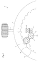
- the invention more particularly relates to a correction device 1 of a display member 2 and conventionally comprises a winding rod 4 mounted rotatably mounted in a plate.
- a sliding pinion 10 is rotatably mounted on the winding stem 4, movable between at least a first correction position and a winding position for example, the winding rod 4 can take a second correction position.
- the sliding pinion 10 meshes with an intermediate gear 11 which meshes with a corrector 12 mounted free to rotate, and which is itself engaged with a first corrective mobile 13 mounted to rotate freely.
- the first correction mobile 13 can also be engaged with a second correction mobile 14, itself engaged with a ring 20 provided with an internal toothing 21, the ring 20 being integral with the body of display 2 and rotationally guided by its outer or inner circumference on the plate.
- the device comprises a rocker 3 for the transmission of a movement between the return corrector 12 carried by a board 30 that includes the rocker 3, and the second corrective mobile 14.
- the corrector 12 is pivotally mounted about a first pivot axis A1 on a shaft 120, which is fixed on a plate in the mode illustrated embodiment.
- This rocker 3 also comprises, pivoted about a second pivot axis A2 on another shaft 121 remote from the first pivot axis A1 and integral with the rocker 3, the first correction mobile 13 carried by the board 30 of the rocker 3.
- the rocker 3 is pivotally mounted between a first and a second correction position, respectively A 'said slow correction position and B' said rapid correction position, about the pivot axis A1 perpendicular to the plate which merges with the pivoting axis of the corrector 12.
- the second correction mobile 14 comprises a number of teeth smaller than that of the first correction mobile 13 so as to increase the speed of the second correction mobile 14.
- the rocker 3 comprises a first friction link between a friction surface of the corrector 12 and a friction surface of the plate 30, or a second frictional connection between a friction surface of the first corrective mobile 13 and a surface of friction of the board 30, so as to rotate the rocker itself from one position to another.
- the device may comprise elastic return means which tend to bring the rocker 3 back into the position of slow correction.
- the first correction mobile unit 13 meshes directly with the internal toothing 21 of the ring 20 of the display member 2.
- the second correction position B' said position of quick fix, the first mobile corrector 13 meshes with the second correction mobile 14, itself engaged with the internal toothing 21 of the ring 20 of the display member 2.
- two accelerator referrals 15 are mounted between the first correction mobile 13 and the second correction mobile 14.
- the operation of the correction device is as follows.
- the winding stem 4 is actuated in a first direction, the clockwise direction for example, in its correction position
- the sliding pinion 10 meshes with the intermediate gear 11 which is engaged with the corrector 12 which is driven in the counterclockwise direction. , and it drives itself, the first corrective mobile 13 in the clockwise direction.
- the latter meshes with the internal toothing 21 of the ring 20 of the display member 2, which rotates clockwise, which makes it possible to correct the information displayed by the display member at a slow correction speed. .
- the winding stem 4 When the winding stem 4 is actuated in a second direction, the counterclockwise direction in this example, in its correction position, the first corrective wheel 13 or the corrector 12 rotates the board 30 around the first axis A1 under the effect friction, until the first corrective mobile 13 meshes with the second corrector mobile 14 which meshes with the internal toothing 21 of the ring 20 of the display member 2, which also rotates clockwise, this which makes it possible to correct the information displayed by the display member according to a fast correction speed.
- the first corrective mobile 13 meshes with a pair of accelerator references 15 which cause the second correction mobile 14, which also makes it possible to correct the information displayed by the display member according to a fast correction speed.
Landscapes
- Physics & Mathematics (AREA)
- General Physics & Mathematics (AREA)
- Astronomy & Astrophysics (AREA)
- Electromechanical Clocks (AREA)
- Electric Clocks (AREA)
Abstract
Dispositif de correction d'une indication fournie par un mécanisme d'affichage pour pièce d'horlogerie munie d'au moins un organe d'affichage, comprenant une tige de remontoir agencée pour occuper au moins une première position de correction de l'indication, un pignon monté solidaire en rotation sur la tige de remontoir, et un renvoi correcteur relié cinématiquement au pignon quand la tige occupe la position de correction. Le dispositif comprend une bascule agencée pour pivoter d'une première position, dite position de correction lente, vers une deuxième position, dite position de correction rapide.Device for correcting an indication provided by a timepiece display mechanism provided with at least one display member, comprising a winding stem arranged to occupy at least a first position for correcting the indication, a pinion mounted rotatably mounted on the winding stem, and a corrective return kinematically connected to the pinion when the rod is in the correct position. The device comprises a rocker arranged to pivot from a first position, said slow correction position, to a second position, said fast correction position.
Description
L'invention concerne un mécanisme de correction rapide pour pièce d'horlogerie comportant un organe de commande commandant un rouage pour le réglage et la correction d'au moins un affichage.The invention relates to a rapid correction mechanism for a timepiece comprising a control member controlling a gear train for adjusting and correcting at least one display.
L'invention concerne encore une pièce d'horlogerie comportant au moins un organe de commande commandant un rouage pour le réglage et la correction d'au moins un affichage.The invention also relates to a timepiece comprising at least one control member controlling a gear train for adjusting and correcting at least one display.
L'invention concerne le domaine de l'horlogerie, et plus particulièrement des pièces d'horlogerie comportant plusieurs affichages.The invention relates to the field of watchmaking, and more particularly to timepieces comprising several displays.
Cette invention concerne les montres qui nécessitent un mécanisme de correction rapide (jour, mois, ou autre) de certaines fonctions, en particulier des fonctions d'affichage telles qu'un quantième (annuel, perpétuel, jour/date, ou autre), ou des indicateurs de phase de lune, de marée, d'affichage AM/PM, ou autres. Un exemple particulier d'un mécanisme de quantième annuel est décrit par le brevet
Pour effectuer une correction du mois, l'utilisateur doit généralement effectuer une correction par le quantième. Dans les cas les plus défavorables, une telle manipulation peut s'avérer longue et fastidieuse. Il se peut que l'on doive effectuer une correction d'une année entière. De même si l'utilisateur se trompe lors de la correction, la manipulation doit être réitérée. L'exécution du mécanisme de correction par le quantième pourrait conduire à un emploi excessif et éventuellement créer des dysfonctionnements.To make a correction of the month, the user must generally make a correction by the date. In the most unfavorable cases, such manipulation can be long and tedious. It may be necessary to make a one-year correction. Similarly if the user is mistaken during the correction, the manipulation must be repeated. The execution of the correction mechanism by the date could lead to excessive use and possibly create malfunctions.
Les mécanismes de correction comportent souvent des bascules, qui sont des composants essentiels dans les mécanismes d'horlogerie, permettant de commuter un mécanisme entre plusieurs modes différents, en général entre deux positions distinctes. Une bascule d'horlogerie est souvent accompagnée d'un ressort de rappel pour assurer une transmission de mouvement correcte, ou un appui maintenu, selon le cas.The correction mechanisms often include flip-flops, which are essential components in clockwork mechanisms, making it possible to switch a mechanism between several different modes, generally between two distinct positions. A clock rocker is often accompanied by a return spring to ensure a proper movement transmission, or a support maintained, as appropriate.
La présente invention se propose de résoudre les inconvénients précités de l'art antérieur, et vise à permettre à l'utilisateur une correction rapide d'un mécanisme, en particulier d'un mécanisme d'affichage, et plus particulièrement d'un mécanisme de quantième, de façon à ce que la mise à jour d'une pièce d'horlogerie, notamment d'une montre, nécessite considérablement moins de corrections manuelles.The present invention proposes to solve the aforementioned drawbacks of the prior art, and aims at enabling the user to quickly correct a mechanism, in particular a display mechanism, and more particularly a mechanism for date, so that the updating of a timepiece, including a watch, requires considerably less manual corrections.
L'invention se propose de mettre à disposition une bascule ne nécessitant pas de ressort de rappel pour assurer la transmission de mouvement, et autonome dans son fonctionnement.The invention proposes to provide a rocker that does not require a return spring to ensure the transmission of movement, and autonomous in its operation.
A cet effet, l'invention concerne une bascule d'horlogerie pour la transmission d'un mouvement entre, d'une part un mobile émetteur que porte une plaque pivotante que comporte ladite bascule et qui est monté pivotant autour d'un premier axe de pivotement, et d'autre part au moins un mobile récepteur externe à ladite bascule laquelle comporte, monté pivotant autour d'un deuxième axe de pivotement distant dudit premier axe de pivotement, au moins un mobile de transmission porté par ladite plaque pivotante.To this end, the invention relates to a watch scale for the transmission of a movement between, on the one hand, a mobile transmitter that carries a pivoting plate that includes said rocker and which is pivotally mounted about a first axis of pivoting, and secondly at least one receiving mobile external to said rocker which comprises, pivotally mounted about a second pivot axis remote from said first pivot axis, at least one transmission mobile carried by said pivot plate.
Conformément à d'autres variantes avantageuses de l'invention :
- Le dispositif comprend une bascule agencée pour pivoter de la première position, dite position de correction lente, vers la deuxième position, dite position correction rapide ;
- la bascule porte le renvoi correcteur et le premier mobile correcteur ;
- la bascule est agencée pour pivoter autour de l'axe de rotation du renvoi correcteur ;
- la bascule comporte une première liaison à friction entre une surface de friction du renvoi correcteur et une surface de friction de la bascule ;
- la bascule comprend une deuxième liaison à friction entre une surface de friction du premier mobile correcteur et une surface de friction de la bascule ;
- le deuxième mobile correcteur comprend un nombre de dents inférieur à celui du premier mobile de correction ;
- le dispositif comprend des renvois accélérateur montés entre le premier mobile correcteur et le deuxième mobile correcteur ;
- le dispositif comprend des moyens de rappel élastique qui tendent à ramener la bascule dans la position de correction lente ;
- l'organe d'affichage est un affichage de phase de lune ou un affichage de quantième ou un affichage de jour ou un affichage de mois ou un affichage de marée ou un affichage de fuseau ;
- The device comprises a rocker arranged to pivot from the first position, said slow correction position, to the second position, said fast correction position;
- the flip-flop carries the corrector and the first correction mobile;
- the rocker is arranged to pivot about the axis of rotation of the corrector;
- the rocker comprises a first friction link between a friction surface of the corrector and a friction surface of the rocker;
- the rocker comprises a second frictional connection between a friction surface of the first corrective mobile and a friction surface of the rocker;
- the second correction mobile comprises a number of teeth less than that of the first correction mobile;
- the device comprises accelerator returns mounted between the first corrective mobile and the second correction mobile;
- the device comprises elastic return means which tend to return the rocker in the slow correction position;
- the display member is a moon phase display or a date display or a day display or a month display or a tide display or a time zone display;
L'invention concerne également une pièce d'horlogerie comprenant un dispositif de correction d'une indication fournie par un mécanisme d'affichage conforme à l'invention.The invention also relates to a timepiece comprising a device for correcting an indication provided by a display mechanism according to the invention.
Grâce à l'invention, la correction lente ou rapide se fait directement par un utilisateur lors d'une rotation de la couronne sans avoir à modifier la position de la couronne.Thanks to the invention, the slow or fast correction is done directly by a user during a rotation of the crown without having to change the position of the crown.
D'autres caractéristiques et avantages de l'invention apparaîtront à la lecture de la description détaillée qui va suivre, en référence aux dessins annexés, où :
- la
figure 1 représente, de façon schématisée un dispositif de correction selon l'invention ; - la
figure 2 représente de façon schématisée un dispositif de correction selon l'invention en position de correction lente ; - la
figure 3 représente de façon schématisée un dispositif de correction selon l'invention en position de correction rapide.
- the
figure 1 schematically represents a correction device according to the invention; - the
figure 2 schematically shows a correction device according to the invention in the slow correction position; - the
figure 3 schematically represents a correction device according to the invention in rapid correction position.
L'invention concerne le domaine des mécanismes d'horlogerie, et plus particulièrement des mécanismes de commande et de transmission de mouvement. Elle trouve une application préférentielle pour la correction et la mise à jour de mécanismes d'affichage.The invention relates to the field of watch mechanisms, and more particularly mechanisms for controlling and transmitting motion. It finds a preferential application for the correction and updating of display mechanisms.
L'invention concerne plus particulièrement un dispositif de correction 1 d'un organe d'affichage 2 et comprend classiquement une tige de remontoir 4 montée guidée en rotation dans une platine. Un pignon coulant 10 est monté solidaire en rotation sur la tige de remontoir 4, mobile entre au moins une première position de correction et une position de remontage par exemple, la tige de remontoir 4 pouvant prendre une seconde position de correction.The invention more particularly relates to a correction device 1 of a
En position de correction, le pignon coulant 10 engrène avec un renvoi intermédiaire 11 qui engrène un renvoi correcteur 12, monté libre en rotation, et qui est lui-même en prise avec un premier mobile correcteur 13 monté libre en rotation également.In the corrected position, the
En position de correction, le premier mobile correcteur 13 peut également être en prise avec un deuxième mobile correcteur 14, lui-même en prise avec une bague 20 munie d'une denture intérieure 21, la bague 20 étant solidaire de l'organe d'affichage 2 et montée guidée en rotation par sa circonférence extérieure ou intérieure sur la platine.In the correction position, the first correction mobile 13 can also be engaged with a second correction mobile 14, itself engaged with a
Selon un aspect avantageux de l'invention, le dispositif comprend une bascule 3 pour la transmission d'un mouvement entre le renvoi correcteur 12 porté par une planche 30 que comporte la bascule 3, et le deuxième mobile correcteur 14. Le renvoi correcteur 12 est monté pivotant autour d'un premier axe de pivotement A1 sur un arbre 120, lequel est fixé sur une platine dans le mode de réalisation illustré.According to an advantageous aspect of the invention, the device comprises a
Cette bascule 3 comporte également, monté pivotant autour d'un deuxième axe de pivotement A2 sur un autre arbre 121 distant du premier axe de pivotement A1 et solidaire de la bascule 3, le premier mobile de correction 13 porté par la planche 30 de la bascule 3.This
La bascule 3 est montée pivotante entre une première et une deuxième position de correction, respectivement A' dite position de correction lente et B' dite position de correction rapide, autour de l' axe de pivotement A1 perpendiculaire à la platine qui se confond avec l'axe de pivotement du renvoi correcteur 12.The
Selon l'invention, le deuxième mobile correcteur 14 comprend un nombre de dents inférieur à celui du premier mobile de correction 13 de manière à augmenter la vitesse du deuxième mobile de correction 14.According to the invention, the second correction mobile 14 comprises a number of teeth smaller than that of the first correction mobile 13 so as to increase the speed of the second correction mobile 14.
Avantageusement, la bascule 3 comporte une première liaison à friction entre une surface de friction du renvoi correcteur 12 et une surface de friction de la planche 30, ou une deuxième liaison à friction entre une surface de friction du premier mobile correcteur 13 et une surface de friction de la planche 30, de manière à faire pivoter la bascule d'elle-même d'une position à l'autre.Advantageously, the
Selon l'invention, le dispositif peut comprendre des moyens de rappel élastique qui tendent à ramener la bascule 3 dans la position de correction lente.According to the invention, the device may comprise elastic return means which tend to bring the
En première position de correction A', dite position de correction lente, le premier mobile correcteur 13 engrène directement avec la denture intérieure 21 de la bague 20 de l'organe d'affichage 2. En deuxième position de correction B', dite position de correction rapide, le premier mobile correcteur 13 engrène avec le deuxième mobile correcteur 14, lui-même en prise avec la denture intérieure 21 de la bague 20 de l'organe d'affichage 2.In the first correction position A ', called the slow correction position, the first correction
Selon un autre mode de réalisation de l'invention, illustré à la
Le fonctionnement du dispositif de correction est le suivant. Lorsque la tige de remontoir 4 est actionnée dans un premier sens, le sens horaire par exemple, dans sa position de correction, le pignon coulant 10 engrène le renvoi intermédiaire 11 qui est en prise avec le renvoi correcteur 12 qui est entraîné dans le sens antihoraire, et il entraîne lui-même, le premier mobile correcteur 13 dans le sens horaire. Ce dernier engrène avec la denture intérieure 21 de la bague 20 de l'organe d'affichage 2, qui tourne dans le sens horaire, ce qui permet de corriger l'information affichée par l'organe d'affichage selon une vitesse de correction lente.The operation of the correction device is as follows. When the winding
Lorsque la tige de remontoir 4 est actionnée dans un deuxième sens, le sens antihoraire dans cet exemple, dans sa position de correction, le premier mobile correcteur 13 ou le renvoi correcteur 12 fait pivoter la planche 30 autour du premier axe A1 sous l'effet de la friction, jusqu'à ce que le premier mobile correcteur 13 engrène avec le deuxième mobile correcteur 14 qui engrène avec la denture intérieure 21 de la bague 20 de l'organe d'affichage 2, qui tourne aussi dans le sens horaire, ce qui permet de corriger l'information affichée par l'organe d'affichage selon une vitesse de correction rapide.When the winding
Dans le mode de réalisation représenté à la
Bien entendu, le dispositif correcteur selon l'invention ne se limite pas aux modes de réalisation qui viennent d'être décrits et diverses modifications et variantes simples peuvent être envisagées par l'homme du métier sans sortir du cadre de l'invention tel que défini par les revendications annexées.Of course, the corrector device according to the invention is not limited to the embodiments which have just been described and various Simple modifications and variations can be envisaged by those skilled in the art without departing from the scope of the invention as defined by the appended claims.
Grâce à ces différents aspects de l'invention, on dispose d'un dispositif correcteur permettant une correction lente ou rapide d'une indication grâce à une seule manipulation de la tige de couronne.Thanks to these different aspects of the invention, there is a corrector device for a slow or fast correction of an indication through a single manipulation of the crown rod.
- 1.1.
- Dispositif de correction,Correction device,
- 10.10.
- Pignon coulant,Sprocket,
- 11.11.
- Renvoi intermédiaire,Intermediate referral,
- 12.12.
- Renvoi correcteur,Cross reference,
- 13.13.
- Premier mobile correcteur,First mobile corrector,
- 14.14.
- Deuxième mobile correcteur,Second mobile corrector,
- 15.15.
- Paire de renvois accélérateurs,Pair of accelerator referrals,
- 2.2.
- Organe d'affichage,Display organ,
- 20.20.
- Bague,Ring,
- 21.21.
- Denture intérieure,Internal teeth,
- 3.3.
- Bascule,Switches,
- 30.30.
- Planche,Board,
- 4.4.
- Tige de remontoir,Winding stem,
- 120.120.
- Arbre du renvoi correcteur,Corrective reference tree,
- 121.121.
- Arbre du premier mobile de correction,Tree of the first mobile correction,
- A1.A1.
- Premier axe de pivotement,First pivot axis,
- A2.A2.
- Deuxième axe de pivotement.Second pivot axis.
Claims (11)
vers une deuxième position, dite position de correction rapide, dans laquelle le premier mobile correcteur est actionné par le renvoi correcteur et coopère avec un deuxième mobile correcteur coopérant avec l'organe d'affichage, pour effectuer une correction rapide de l'indication lorsque la tige de remontoir est actionnée dans un deuxième sens de rotation dans sa position de correction.An indication correcting device provided by a timepiece display mechanism provided with at least one display member, comprising:
to a second position, said fast correction position, wherein the first correction mobile is actuated by the corrective return and cooperates with a second correction mobile cooperating with the display member, to perform a rapid correction of the indication when the winding stem is actuated in a second direction of rotation in its correction position.
Priority Applications (1)
| Application Number | Priority Date | Filing Date | Title |
|---|---|---|---|
| EP16170428.3A EP3246763B1 (en) | 2016-05-19 | 2016-05-19 | Quick correction mechanism for clock piece |
Applications Claiming Priority (1)
| Application Number | Priority Date | Filing Date | Title |
|---|---|---|---|
| EP16170428.3A EP3246763B1 (en) | 2016-05-19 | 2016-05-19 | Quick correction mechanism for clock piece |
Publications (2)
| Publication Number | Publication Date |
|---|---|
| EP3246763A1 true EP3246763A1 (en) | 2017-11-22 |
| EP3246763B1 EP3246763B1 (en) | 2019-12-04 |
Family
ID=56024194
Family Applications (1)
| Application Number | Title | Priority Date | Filing Date |
|---|---|---|---|
| EP16170428.3A Active EP3246763B1 (en) | 2016-05-19 | 2016-05-19 | Quick correction mechanism for clock piece |
Country Status (1)
| Country | Link |
|---|---|
| EP (1) | EP3246763B1 (en) |
Cited By (3)
| Publication number | Priority date | Publication date | Assignee | Title |
|---|---|---|---|---|
| CN112666818A (en) * | 2020-12-28 | 2021-04-16 | 深圳穿金戴银科技股份有限公司 | Watch timing structure |
| CN113391538A (en) * | 2021-07-09 | 2021-09-14 | 深圳市古尊表业有限公司 | Structure that lockable wrist-watch was pressed |
| CN114879471A (en) * | 2022-06-02 | 2022-08-09 | 天津海鸥表业集团有限公司 | Quick-dialing mechanism, coaxial display system and watch |
Citations (4)
| Publication number | Priority date | Publication date | Assignee | Title |
|---|---|---|---|---|
| JPH08285958A (en) * | 1995-04-13 | 1996-11-01 | Rhythm Watch Co Ltd | Speed conversion mechanism of gear train |
| EP1115041A1 (en) * | 2000-01-06 | 2001-07-11 | Chopard Manufacture SA | Fast correction device for calendar watch |
| EP1666991B1 (en) | 2004-12-02 | 2011-06-01 | ETA SA Manufacture Horlogère Suisse | Annual calendar mechanism for a timepiece |
| EP2945026A1 (en) * | 2014-05-14 | 2015-11-18 | ETA SA Manufacture Horlogère Suisse | Quick correction mechanism of a timepiece |
-
2016
- 2016-05-19 EP EP16170428.3A patent/EP3246763B1/en active Active
Patent Citations (4)
| Publication number | Priority date | Publication date | Assignee | Title |
|---|---|---|---|---|
| JPH08285958A (en) * | 1995-04-13 | 1996-11-01 | Rhythm Watch Co Ltd | Speed conversion mechanism of gear train |
| EP1115041A1 (en) * | 2000-01-06 | 2001-07-11 | Chopard Manufacture SA | Fast correction device for calendar watch |
| EP1666991B1 (en) | 2004-12-02 | 2011-06-01 | ETA SA Manufacture Horlogère Suisse | Annual calendar mechanism for a timepiece |
| EP2945026A1 (en) * | 2014-05-14 | 2015-11-18 | ETA SA Manufacture Horlogère Suisse | Quick correction mechanism of a timepiece |
Cited By (3)
| Publication number | Priority date | Publication date | Assignee | Title |
|---|---|---|---|---|
| CN112666818A (en) * | 2020-12-28 | 2021-04-16 | 深圳穿金戴银科技股份有限公司 | Watch timing structure |
| CN113391538A (en) * | 2021-07-09 | 2021-09-14 | 深圳市古尊表业有限公司 | Structure that lockable wrist-watch was pressed |
| CN114879471A (en) * | 2022-06-02 | 2022-08-09 | 天津海鸥表业集团有限公司 | Quick-dialing mechanism, coaxial display system and watch |
Also Published As
| Publication number | Publication date |
|---|---|
| EP3246763B1 (en) | 2019-12-04 |
Similar Documents
| Publication | Publication Date | Title |
|---|---|---|
| EP2945026B1 (en) | Quick correction mechanism of a timepiece | |
| EP2115537A2 (en) | Timepiece comprising a mechanism for driving a device displaying a time-related value | |
| EP3144743B1 (en) | Clock movement comprising a mechanism for correcting the date | |
| EP1970778A1 (en) | Timepiece comprising a device indicating the power reserve | |
| EP1862871B1 (en) | Timepiece comprising an improved time-setting mechanism | |
| EP3246763B1 (en) | Quick correction mechanism for clock piece | |
| CH713604A1 (en) | Selection and actuation mechanism as well as a device for adjusting the functions of a timepiece. | |
| CH712477A2 (en) | Rapid correction device for an indication provided by a display mechanism for a timepiece. | |
| EP3485333B1 (en) | Mechanism for selecting and actuating functions of a timepiece movement | |
| EP2477080B1 (en) | Timepiece showing the time zone corresponding to a selected time | |
| CH339129A (en) | Timepiece with instantaneous dates | |
| CH705128B1 (en) | Device date display and moon phase. | |
| CH710450A1 (en) | Timepiece fitted with an orbital view. | |
| EP2933692A1 (en) | Display device | |
| EP1353244B1 (en) | Timepiece with oblong shaped case | |
| EP0479147B1 (en) | Mechanical and/or electromechanical timepiece | |
| CH698613B1 (en) | Timepiece e.g. watch, has time marking equation mechanism including action unit that connects civil time minute wheel to real time minute wheel for suppressing clearance between civil time minute hand and real time minute real hand | |
| EP0563745B1 (en) | Clockwork provided with guide means of a control organ such as a stem | |
| FR2973125A1 (en) | SUPPORT FOR MOVING WATCH DISPLAY MEMORY | |
| FR3023934A1 (en) | WATCHMAKING MECHANISM | |
| CH720264A2 (en) | Watch movement comprising a display correction mechanism | |
| EP4012505A1 (en) | Timepiece device with anti-blocking mobile | |
| EP4375763A1 (en) | Clock movement comprising a mechanism for correcting a display | |
| WO2008148735A1 (en) | Device for correcting a display mechanism for a timepiece | |
| CH713730A2 (en) | Remote control mechanism for watchmaking. |
Legal Events
| Date | Code | Title | Description |
|---|---|---|---|
| PUAI | Public reference made under article 153(3) epc to a published international application that has entered the european phase |
Free format text: ORIGINAL CODE: 0009012 |
|
| STAA | Information on the status of an ep patent application or granted ep patent |
Free format text: STATUS: THE APPLICATION HAS BEEN PUBLISHED |
|
| AK | Designated contracting states |
Kind code of ref document: A1 Designated state(s): AL AT BE BG CH CY CZ DE DK EE ES FI FR GB GR HR HU IE IS IT LI LT LU LV MC MK MT NL NO PL PT RO RS SE SI SK SM TR |
|
| AX | Request for extension of the european patent |
Extension state: BA ME |
|
| STAA | Information on the status of an ep patent application or granted ep patent |
Free format text: STATUS: REQUEST FOR EXAMINATION WAS MADE |
|
| 17P | Request for examination filed |
Effective date: 20180522 |
|
| RBV | Designated contracting states (corrected) |
Designated state(s): AL AT BE BG CH CY CZ DE DK EE ES FI FR GB GR HR HU IE IS IT LI LT LU LV MC MK MT NL NO PL PT RO RS SE SI SK SM TR |
|
| GRAP | Despatch of communication of intention to grant a patent |
Free format text: ORIGINAL CODE: EPIDOSNIGR1 |
|
| STAA | Information on the status of an ep patent application or granted ep patent |
Free format text: STATUS: GRANT OF PATENT IS INTENDED |
|
| INTG | Intention to grant announced |
Effective date: 20190807 |
|
| GRAS | Grant fee paid |
Free format text: ORIGINAL CODE: EPIDOSNIGR3 |
|
| GRAA | (expected) grant |
Free format text: ORIGINAL CODE: 0009210 |
|
| STAA | Information on the status of an ep patent application or granted ep patent |
Free format text: STATUS: THE PATENT HAS BEEN GRANTED |
|
| AK | Designated contracting states |
Kind code of ref document: B1 Designated state(s): AL AT BE BG CH CY CZ DE DK EE ES FI FR GB GR HR HU IE IS IT LI LT LU LV MC MK MT NL NO PL PT RO RS SE SI SK SM TR |
|
| REG | Reference to a national code |
Ref country code: GB Ref legal event code: FG4D Free format text: NOT ENGLISH |
|
| REG | Reference to a national code |
Ref country code: CH Ref legal event code: EP Ref country code: CH Ref legal event code: NV Representative=s name: ICB INGENIEURS CONSEILS EN BREVETS SA, CH |
|
| REG | Reference to a national code |
Ref country code: AT Ref legal event code: REF Ref document number: 1210140 Country of ref document: AT Kind code of ref document: T Effective date: 20191215 |
|
| REG | Reference to a national code |
Ref country code: DE Ref legal event code: R096 Ref document number: 602016025373 Country of ref document: DE |
|
| REG | Reference to a national code |
Ref country code: IE Ref legal event code: FG4D Free format text: LANGUAGE OF EP DOCUMENT: FRENCH |
|
| REG | Reference to a national code |
Ref country code: NL Ref legal event code: MP Effective date: 20191204 |
|
| REG | Reference to a national code |
Ref country code: LT Ref legal event code: MG4D |
|
| PG25 | Lapsed in a contracting state [announced via postgrant information from national office to epo] |
Ref country code: GR Free format text: LAPSE BECAUSE OF FAILURE TO SUBMIT A TRANSLATION OF THE DESCRIPTION OR TO PAY THE FEE WITHIN THE PRESCRIBED TIME-LIMIT Effective date: 20200305 Ref country code: NO Free format text: LAPSE BECAUSE OF FAILURE TO SUBMIT A TRANSLATION OF THE DESCRIPTION OR TO PAY THE FEE WITHIN THE PRESCRIBED TIME-LIMIT Effective date: 20200304 Ref country code: BG Free format text: LAPSE BECAUSE OF FAILURE TO SUBMIT A TRANSLATION OF THE DESCRIPTION OR TO PAY THE FEE WITHIN THE PRESCRIBED TIME-LIMIT Effective date: 20200304 Ref country code: FI Free format text: LAPSE BECAUSE OF FAILURE TO SUBMIT A TRANSLATION OF THE DESCRIPTION OR TO PAY THE FEE WITHIN THE PRESCRIBED TIME-LIMIT Effective date: 20191204 Ref country code: LV Free format text: LAPSE BECAUSE OF FAILURE TO SUBMIT A TRANSLATION OF THE DESCRIPTION OR TO PAY THE FEE WITHIN THE PRESCRIBED TIME-LIMIT Effective date: 20191204 Ref country code: SE Free format text: LAPSE BECAUSE OF FAILURE TO SUBMIT A TRANSLATION OF THE DESCRIPTION OR TO PAY THE FEE WITHIN THE PRESCRIBED TIME-LIMIT Effective date: 20191204 Ref country code: LT Free format text: LAPSE BECAUSE OF FAILURE TO SUBMIT A TRANSLATION OF THE DESCRIPTION OR TO PAY THE FEE WITHIN THE PRESCRIBED TIME-LIMIT Effective date: 20191204 |
|
| PG25 | Lapsed in a contracting state [announced via postgrant information from national office to epo] |
Ref country code: HR Free format text: LAPSE BECAUSE OF FAILURE TO SUBMIT A TRANSLATION OF THE DESCRIPTION OR TO PAY THE FEE WITHIN THE PRESCRIBED TIME-LIMIT Effective date: 20191204 Ref country code: RS Free format text: LAPSE BECAUSE OF FAILURE TO SUBMIT A TRANSLATION OF THE DESCRIPTION OR TO PAY THE FEE WITHIN THE PRESCRIBED TIME-LIMIT Effective date: 20191204 |
|
| PG25 | Lapsed in a contracting state [announced via postgrant information from national office to epo] |
Ref country code: AL Free format text: LAPSE BECAUSE OF FAILURE TO SUBMIT A TRANSLATION OF THE DESCRIPTION OR TO PAY THE FEE WITHIN THE PRESCRIBED TIME-LIMIT Effective date: 20191204 |
|
| PG25 | Lapsed in a contracting state [announced via postgrant information from national office to epo] |
Ref country code: CZ Free format text: LAPSE BECAUSE OF FAILURE TO SUBMIT A TRANSLATION OF THE DESCRIPTION OR TO PAY THE FEE WITHIN THE PRESCRIBED TIME-LIMIT Effective date: 20191204 Ref country code: RO Free format text: LAPSE BECAUSE OF FAILURE TO SUBMIT A TRANSLATION OF THE DESCRIPTION OR TO PAY THE FEE WITHIN THE PRESCRIBED TIME-LIMIT Effective date: 20191204 Ref country code: PT Free format text: LAPSE BECAUSE OF FAILURE TO SUBMIT A TRANSLATION OF THE DESCRIPTION OR TO PAY THE FEE WITHIN THE PRESCRIBED TIME-LIMIT Effective date: 20200429 Ref country code: EE Free format text: LAPSE BECAUSE OF FAILURE TO SUBMIT A TRANSLATION OF THE DESCRIPTION OR TO PAY THE FEE WITHIN THE PRESCRIBED TIME-LIMIT Effective date: 20191204 Ref country code: NL Free format text: LAPSE BECAUSE OF FAILURE TO SUBMIT A TRANSLATION OF THE DESCRIPTION OR TO PAY THE FEE WITHIN THE PRESCRIBED TIME-LIMIT Effective date: 20191204 Ref country code: ES Free format text: LAPSE BECAUSE OF FAILURE TO SUBMIT A TRANSLATION OF THE DESCRIPTION OR TO PAY THE FEE WITHIN THE PRESCRIBED TIME-LIMIT Effective date: 20191204 |
|
| PG25 | Lapsed in a contracting state [announced via postgrant information from national office to epo] |
Ref country code: SK Free format text: LAPSE BECAUSE OF FAILURE TO SUBMIT A TRANSLATION OF THE DESCRIPTION OR TO PAY THE FEE WITHIN THE PRESCRIBED TIME-LIMIT Effective date: 20191204 Ref country code: SM Free format text: LAPSE BECAUSE OF FAILURE TO SUBMIT A TRANSLATION OF THE DESCRIPTION OR TO PAY THE FEE WITHIN THE PRESCRIBED TIME-LIMIT Effective date: 20191204 Ref country code: IS Free format text: LAPSE BECAUSE OF FAILURE TO SUBMIT A TRANSLATION OF THE DESCRIPTION OR TO PAY THE FEE WITHIN THE PRESCRIBED TIME-LIMIT Effective date: 20200404 |
|
| REG | Reference to a national code |
Ref country code: DE Ref legal event code: R097 Ref document number: 602016025373 Country of ref document: DE |
|
| REG | Reference to a national code |
Ref country code: AT Ref legal event code: MK05 Ref document number: 1210140 Country of ref document: AT Kind code of ref document: T Effective date: 20191204 |
|
| PLBE | No opposition filed within time limit |
Free format text: ORIGINAL CODE: 0009261 |
|
| STAA | Information on the status of an ep patent application or granted ep patent |
Free format text: STATUS: NO OPPOSITION FILED WITHIN TIME LIMIT |
|
| PG25 | Lapsed in a contracting state [announced via postgrant information from national office to epo] |
Ref country code: DK Free format text: LAPSE BECAUSE OF FAILURE TO SUBMIT A TRANSLATION OF THE DESCRIPTION OR TO PAY THE FEE WITHIN THE PRESCRIBED TIME-LIMIT Effective date: 20191204 |
|
| 26N | No opposition filed |
Effective date: 20200907 |
|
| PG25 | Lapsed in a contracting state [announced via postgrant information from national office to epo] |
Ref country code: AT Free format text: LAPSE BECAUSE OF FAILURE TO SUBMIT A TRANSLATION OF THE DESCRIPTION OR TO PAY THE FEE WITHIN THE PRESCRIBED TIME-LIMIT Effective date: 20191204 Ref country code: SI Free format text: LAPSE BECAUSE OF FAILURE TO SUBMIT A TRANSLATION OF THE DESCRIPTION OR TO PAY THE FEE WITHIN THE PRESCRIBED TIME-LIMIT Effective date: 20191204 Ref country code: PL Free format text: LAPSE BECAUSE OF FAILURE TO SUBMIT A TRANSLATION OF THE DESCRIPTION OR TO PAY THE FEE WITHIN THE PRESCRIBED TIME-LIMIT Effective date: 20191204 |
|
| PG25 | Lapsed in a contracting state [announced via postgrant information from national office to epo] |
Ref country code: IT Free format text: LAPSE BECAUSE OF FAILURE TO SUBMIT A TRANSLATION OF THE DESCRIPTION OR TO PAY THE FEE WITHIN THE PRESCRIBED TIME-LIMIT Effective date: 20191204 Ref country code: MC Free format text: LAPSE BECAUSE OF FAILURE TO SUBMIT A TRANSLATION OF THE DESCRIPTION OR TO PAY THE FEE WITHIN THE PRESCRIBED TIME-LIMIT Effective date: 20191204 |
|
| REG | Reference to a national code |
Ref country code: BE Ref legal event code: MM Effective date: 20200531 |
|
| GBPC | Gb: european patent ceased through non-payment of renewal fee |
Effective date: 20200519 |
|
| PG25 | Lapsed in a contracting state [announced via postgrant information from national office to epo] |
Ref country code: LU Free format text: LAPSE BECAUSE OF NON-PAYMENT OF DUE FEES Effective date: 20200519 |
|
| PG25 | Lapsed in a contracting state [announced via postgrant information from national office to epo] |
Ref country code: GB Free format text: LAPSE BECAUSE OF NON-PAYMENT OF DUE FEES Effective date: 20200519 Ref country code: IE Free format text: LAPSE BECAUSE OF NON-PAYMENT OF DUE FEES Effective date: 20200519 |
|
| PG25 | Lapsed in a contracting state [announced via postgrant information from national office to epo] |
Ref country code: BE Free format text: LAPSE BECAUSE OF NON-PAYMENT OF DUE FEES Effective date: 20200531 |
|
| PG25 | Lapsed in a contracting state [announced via postgrant information from national office to epo] |
Ref country code: TR Free format text: LAPSE BECAUSE OF FAILURE TO SUBMIT A TRANSLATION OF THE DESCRIPTION OR TO PAY THE FEE WITHIN THE PRESCRIBED TIME-LIMIT Effective date: 20191204 Ref country code: MT Free format text: LAPSE BECAUSE OF FAILURE TO SUBMIT A TRANSLATION OF THE DESCRIPTION OR TO PAY THE FEE WITHIN THE PRESCRIBED TIME-LIMIT Effective date: 20191204 Ref country code: CY Free format text: LAPSE BECAUSE OF FAILURE TO SUBMIT A TRANSLATION OF THE DESCRIPTION OR TO PAY THE FEE WITHIN THE PRESCRIBED TIME-LIMIT Effective date: 20191204 |
|
| PG25 | Lapsed in a contracting state [announced via postgrant information from national office to epo] |
Ref country code: MK Free format text: LAPSE BECAUSE OF FAILURE TO SUBMIT A TRANSLATION OF THE DESCRIPTION OR TO PAY THE FEE WITHIN THE PRESCRIBED TIME-LIMIT Effective date: 20191204 |
|
| P01 | Opt-out of the competence of the unified patent court (upc) registered |
Effective date: 20230701 |
|
| PGFP | Annual fee paid to national office [announced via postgrant information from national office to epo] |
Ref country code: DE Payment date: 20240418 Year of fee payment: 9 |
|
| PGFP | Annual fee paid to national office [announced via postgrant information from national office to epo] |
Ref country code: CH Payment date: 20240602 Year of fee payment: 9 |
|
| PGFP | Annual fee paid to national office [announced via postgrant information from national office to epo] |
Ref country code: FR Payment date: 20240418 Year of fee payment: 9 |