EP3246096B1 - Spraying device and use of same - Google Patents
Spraying device and use of same Download PDFInfo
- Publication number
- EP3246096B1 EP3246096B1 EP17175982.2A EP17175982A EP3246096B1 EP 3246096 B1 EP3246096 B1 EP 3246096B1 EP 17175982 A EP17175982 A EP 17175982A EP 3246096 B1 EP3246096 B1 EP 3246096B1
- Authority
- EP
- European Patent Office
- Prior art keywords
- front wall
- spraying device
- holes
- side wall
- pusher
- Prior art date
- Legal status (The legal status is an assumption and is not a legal conclusion. Google has not performed a legal analysis and makes no representation as to the accuracy of the status listed.)
- Active
Links
- 238000005507 spraying Methods 0.000 title claims description 53
- 239000012530 fluid Substances 0.000 claims description 38
- 239000000443 aerosol Substances 0.000 claims description 16
- -1 polyethylene Polymers 0.000 claims description 13
- 229920000728 polyester Polymers 0.000 claims description 11
- 239000000463 material Substances 0.000 claims description 10
- 229920000642 polymer Polymers 0.000 claims description 8
- 239000004033 plastic Substances 0.000 claims description 5
- 229920003023 plastic Polymers 0.000 claims description 5
- 239000004698 Polyethylene Substances 0.000 claims description 4
- 239000004743 Polypropylene Substances 0.000 claims description 4
- 229920000573 polyethylene Polymers 0.000 claims description 4
- 229920001155 polypropylene Polymers 0.000 claims description 4
- 229910045601 alloy Inorganic materials 0.000 claims description 3
- 239000000956 alloy Substances 0.000 claims description 3
- 239000000919 ceramic Substances 0.000 claims description 3
- 239000011248 coating agent Substances 0.000 claims description 3
- 238000000576 coating method Methods 0.000 claims description 3
- 239000011521 glass Substances 0.000 claims description 3
- 229910052751 metal Inorganic materials 0.000 claims description 3
- 239000002184 metal Substances 0.000 claims description 3
- 239000007769 metal material Substances 0.000 claims description 3
- 150000002739 metals Chemical class 0.000 claims description 3
- 239000010703 silicon Substances 0.000 claims description 3
- 229910052710 silicon Inorganic materials 0.000 claims description 3
- 230000002093 peripheral effect Effects 0.000 claims description 2
- 239000007921 spray Substances 0.000 description 50
- 239000000047 product Substances 0.000 description 36
- 239000000825 pharmaceutical preparation Substances 0.000 description 13
- 229940127557 pharmaceutical product Drugs 0.000 description 13
- 239000007788 liquid Substances 0.000 description 6
- 238000011282 treatment Methods 0.000 description 6
- 210000000621 bronchi Anatomy 0.000 description 5
- 239000002537 cosmetic Substances 0.000 description 5
- 239000002304 perfume Substances 0.000 description 5
- XUIMIQQOPSSXEZ-UHFFFAOYSA-N Silicon Chemical compound [Si] XUIMIQQOPSSXEZ-UHFFFAOYSA-N 0.000 description 3
- 210000004072 lung Anatomy 0.000 description 3
- 210000003437 trachea Anatomy 0.000 description 3
- 230000001476 alcoholic effect Effects 0.000 description 2
- 229910052782 aluminium Inorganic materials 0.000 description 2
- XAGFODPZIPBFFR-UHFFFAOYSA-N aluminium Chemical compound [Al] XAGFODPZIPBFFR-UHFFFAOYSA-N 0.000 description 2
- 230000000295 complement effect Effects 0.000 description 2
- 230000001419 dependent effect Effects 0.000 description 2
- 239000006185 dispersion Substances 0.000 description 2
- 229920006324 polyoxymethylene Polymers 0.000 description 2
- 229930182556 Polyacetal Natural products 0.000 description 1
- 241001639412 Verres Species 0.000 description 1
- 239000004411 aluminium Substances 0.000 description 1
- 229920001577 copolymer Polymers 0.000 description 1
- 230000001627 detrimental effect Effects 0.000 description 1
- 238000005194 fractionation Methods 0.000 description 1
- 239000012263 liquid product Substances 0.000 description 1
- 238000004519 manufacturing process Methods 0.000 description 1
- 229920000098 polyolefin Polymers 0.000 description 1
- 230000000284 resting effect Effects 0.000 description 1
Images


Classifications
-
- B—PERFORMING OPERATIONS; TRANSPORTING
- B05—SPRAYING OR ATOMISING IN GENERAL; APPLYING FLUENT MATERIALS TO SURFACES, IN GENERAL
- B05B—SPRAYING APPARATUS; ATOMISING APPARATUS; NOZZLES
- B05B1/00—Nozzles, spray heads or other outlets, with or without auxiliary devices such as valves, heating means
- B05B1/14—Nozzles, spray heads or other outlets, with or without auxiliary devices such as valves, heating means with multiple outlet openings; with strainers in or outside the outlet opening
- B05B1/18—Roses; Shower heads
- B05B1/185—Roses; Shower heads characterised by their outlet element; Mounting arrangements therefor
-
- B—PERFORMING OPERATIONS; TRANSPORTING
- B65—CONVEYING; PACKING; STORING; HANDLING THIN OR FILAMENTARY MATERIAL
- B65D—CONTAINERS FOR STORAGE OR TRANSPORT OF ARTICLES OR MATERIALS, e.g. BAGS, BARRELS, BOTTLES, BOXES, CANS, CARTONS, CRATES, DRUMS, JARS, TANKS, HOPPERS, FORWARDING CONTAINERS; ACCESSORIES, CLOSURES, OR FITTINGS THEREFOR; PACKAGING ELEMENTS; PACKAGES
- B65D83/00—Containers or packages with special means for dispensing contents
- B65D83/14—Containers or packages with special means for dispensing contents for delivery of liquid or semi-liquid contents by internal gaseous pressure, i.e. aerosol containers comprising propellant for a product delivered by a propellant
- B65D83/75—Aerosol containers not provided for in groups B65D83/16 - B65D83/74
- B65D83/753—Aerosol containers not provided for in groups B65D83/16 - B65D83/74 characterised by details or accessories associated with outlets
-
- B—PERFORMING OPERATIONS; TRANSPORTING
- B05—SPRAYING OR ATOMISING IN GENERAL; APPLYING FLUENT MATERIALS TO SURFACES, IN GENERAL
- B05B—SPRAYING APPARATUS; ATOMISING APPARATUS; NOZZLES
- B05B11/00—Single-unit hand-held apparatus in which flow of contents is produced by the muscular force of the operator at the moment of use
- B05B11/01—Single-unit hand-held apparatus in which flow of contents is produced by the muscular force of the operator at the moment of use characterised by the means producing the flow
- B05B11/10—Pump arrangements for transferring the contents from the container to a pump chamber by a sucking effect and forcing the contents out through the dispensing nozzle
Definitions
- the present invention relates to a spray device and to a use of this device.
- the document US-A-6 145 712 describes an example of such a spray device, in which the front face of the spray nozzle has a single central hole.
- the spray nozzles which are conventionally mounted on pumps or on spray valves, have the drawback of causing a large dispersion in the diameter of the droplets of sprayed fluid.
- the fractionation of the fluid product into fine droplets is obtained by a dynamic phenomenon which is particularly difficult to control, generally consisting in creating a vortex in the inner chamber of the nozzle and in splitting the fluid. fluid product in fine droplets when it exits at very high speed through the central hole.
- spray devices are described in WO03 / 020436A , EP 1 698 399 A , EP0 613 836 A , WO 02/0201981 A , JP 2002 186882A and US 6 341 735 B1 .
- the sprayed product consists of droplets having diameters between 5 ⁇ m and 300 ⁇ m.
- This dispersion may prove to be undesirable when it is desired to spray droplets of substantially homogeneous sizes. For example, one may wish to spray small droplets for inhaling medicinal treatments of the bronchi, or else one may wish to spray larger size drops for cosmetic or perfume applications, so that the droplets penetrate the least. possible in the user's bronchi.
- droplets of very different sizes also follow very different paths, which is detrimental for a controlled application of the sprayed product.
- oversized droplets may fall on the user's clothing instead of being projected onto the skin, risking indelible stains. .
- the object of the present invention is in particular to overcome these drawbacks.
- the invention provides a spray device of the aforementioned type in which the front wall comprises a plurality of calibrated holes each having a diameter between 1 and 100 ⁇ m, the diameter of each hole not differing by more than 20%. an average of the diameters of the various holes, the front wall being elastically deformable between a state of rest, in which said front wall is flat, and an actuation state when the fluid under pressure is transferred into the inner chamber, in wherein said front wall has an outwardly facing convexity.
- the term “diameter” does not necessarily imply that this section is circular.
- the holes in the front face could, where appropriate, have a polygonal section, for example square, without departing from the scope of the present invention.
- the aforementioned diameter would be the diameter equivalent of the hole, that is to say the diameter of a circular hole having a section of the same area as the polygonal hole. If the holes are not of constant section along their length, the diameter in question is the diameter of the minimum section of the holes.
- the size of the droplets sprayed by the spraying device is controlled and good homogeneity of this size of the droplets is ensured.
- the aforementioned arrangements also make it possible at least partially to overcome the pressure differences with which the fluid is fed into the interior chamber of the spray nozzle, since experience shows that the size of the droplets obtained by virtue of the The present invention is not very dependent on this pressure (the pressure differences in question may arise, for example, from differences in the actuating force of a user if the fluid product is supplied by means of a manual pump, or even when the fluid product is supplied through a valve from a pressurized product tank, the pressure differences in question may come from the fact that the tank has already been partially emptied by previous uses of the spray device).
- the invention aims to improve control over the shape of the aerosol obtained at the outlet of the spray nozzle while allowing simplified production of the calibrated holes.
- the front wall is elastically deformable between a state of rest, in which said front wall is flat, and an actuation state when fluid under pressure is transferred into the inner chamber, in which said front wall has a convexity turned outwards.
- the holes can be made in a simple manner in the flat front wall, each hole possibly having an axis which extends in a plane parallel to a central axis perpendicular to the front wall.
- the axes of the holes move away from the central axis so as to present an outward divergence and the fluid product can be sprayed in the form of 'an aerosol with a high opening angle.
- the invention aims to improve control over the distribution of droplets and the shape of the aerosol.
- the holes in the front wall are distributed around a center, each hole extends along an axis inclined with respect to the normal to said front wall at the level of said hole, said axis and said normal defining a plane substantially tangent to a circle centered on said central point and passing through the hole, and the axes of all the holes having an inclination with respect to the corresponding normal, and said axes of all the holes holes being inclined in the direction of the same angular direction around said central point so as to generate a swirling aerosol when fluid is sprayed from said nozzle.
- the aerosol may have, in the vicinity of the spray nozzle, a first substantially conical portion having a high opening angle and a second portion substantially symmetrical with respect to the central axis of the nozzle.
- a subject of the invention is also the use of a spraying device as defined above, for spraying a non-gaseous fluid product.
- the figure 1 represents a spraying device 1 suitable for spraying a non-gaseous fluid product 2 contained in a reservoir 3.
- the fluid product in question can be a liquid or semi-liquid product, for example a pharmaceutical product, a cosmetic product, a perfume product Or other.
- the dynamic viscosity of the fluid 2 is generally less than 50 cps (centipoise) at 20 ° C.
- the spraying device 1 further comprises a dispensing device 4 which is fixed so known to a neck 5 of the reservoir 3 at the upper end of said reservoir.
- the dispensing device 4 can for example be a manual spray pump or else a spray valve, in which case the reservoir 3 is under pressure.
- the dispensing device 4 comprises a fluid product inlet 6, oriented downwards, which communicates with the bottom of the reservoir 3 via a dip tube 7, and a hollow actuating rod 8 that protrudes upwards.
- a push button 9 is fitted to the upper end of the actuating rod 8, and serves both for actuating the dispensing device 4 and for the output of the sprayed fluid, output which takes place through the actuating rod 8, according to the arrow 10 shown on the figure 2 .
- the dispensing device shown in figure 1 could, alternatively, be used in the inverted position, that is to say the bottom of the tank 3 facing upwards.
- the distribution device 4 would not include a dip tube 7.
- the pusher 9 can for example be molded in a single piece of plastic, in particular a polyolefin, for example polypropylene or the like.
- the pusher 9 comprises a substantially horizontal upper wall 11 and a substantially cylindrical and vertical skirt 12 which extends from the periphery of the upper wall 11.
- the pusher 9 further comprises a central well 13 which extends vertically downward from the upper wall 11, in the center of the side wall 12. The upper end of the actuating rod 8 is fitted. in the central well 13.
- a lateral passage 14 which communicates with a housing for receiving the nozzle 15 of substantially cylindrical shape, extending substantially horizontally along a central axis X and opening outwards from the pusher 9.
- the side wall 18 of the spray nozzle 16 may include, at its end opposite the front wall 17, an annular gaudron 19 which projects radially outwards and which penetrates into the material of the pusher 9 for anchor spray tip 16 in nozzle housing 15.
- the spray nozzle 16 delimits, with the pusher 9, an interior chamber 20 which communicates with the aforementioned passage 14 and which receives the fluid product to be sprayed upon actuation of the dispensing device 4.
- the pusher 9 may include a core 21 which protrudes inside the side wall 18 of the spray nozzle to limit the volume of this interior chamber 20.
- the front wall 17 of the spray nozzle has a plurality of holes 22 which are distributed over the surface of said front face.
- the holes 22 can be 10 to 1000 in number, for example.
- the diameter of each hole 22 is generally between 1 and 100 ⁇ m, all the holes 22 being substantially of the same diameter.
- the diameter of each hole 22 does not differ from the average value of the diameters of the various holes 22 by more than 20% and advantageously, the diameter of each hole 22 does not differ from said average value by more than 10%.
- the holes 22 may be of substantially cylindrical shape with a circular section, but they could optionally have a polygonal section, for example square, in which case the aforementioned diameter would be the equivalent diameter of the hole, that is to say the diameter d 'a circular hole having a section of the same area as the polygonal hole.
- the front wall 17 may have a convex shape with a concavity facing inward, as in the example shown in FIG. figure 3 , but said front wall may be flat or have any other desired shape.
- the front wall 17 may have a thickness e generally between 0.08 and 1.5 mm, in particular between 0.2 and 0.4 mm.
- the holes 22 may have a constant section, as in the example shown, but the holes 22 could, where appropriate, have portions flared inward and / or outward, in which case the length of the holes 22 to be taken into account. account would be the length in which these holes have a constant section and the diameter to be taken into account would be the diameter of the minimum section.
- the length of the holes 22 in their part with constant section is generally between 0.08 and 0.5 mm, advantageously between 0.08 and 0.3 mm, and more advantageously still between 0.08 and 0.2 mm, in particular equal to approximately 0.1 mm.
- the pusher 9 when a user presses the pusher 9, the latter actuates the dispensing device 4, which supplies the inner chamber 20 of the nozzle with pressurized fluid, at a pressure generally less than 7 bars, for example order of 5 bars.
- the fluid product is expelled through the calibrated holes 22 of the front wall 17, which produces an aerosol 23 of fine droplets of relatively homogeneous size and little dependent on the exact value of the pressure of the fluid product in the interior chamber 20.
- the spray nozzle 16 differs from the spray nozzle previously described in that the front wall 17b is elastically deformable between a rest state shown in the figure. figure 4 and an actuation state shown in figure 5 , when the pressurized fluid product is transferred into the inner chamber 20.
- the front wall 17b in the rest state, extends in a plane perpendicular to the central axis X. And in the actuation state, the front wall 17b has a convexity facing outwardly. so, for example, to have the shape of a spherical cap.
- the front wall 17b is flat.
- This arrangement makes it possible to produce in a simple manner the holes 22 having an axis which extends, for example, along a normal to the front wall 17b, parallel to the central axis X.
- the pressurized fluid product is transferred into the inner chamber 20 exerting a force on the front wall 17b so as to cause it to pass into the actuation state.
- the axes of the holes 22 move away from the central axis X so as to present an outward divergence.
- the fluid product is expelled through the holes 22 diverging from the front wall 17b, which produces an aerosol 23 of fine droplets of relatively homogeneous size, the aerosol 23 being substantially conical with a high cone angle ⁇ .
- the side wall 18 is a separate part of the pusher 9, secured to the pusher 9, and the front wall 17b integrally with the side wall 18 is made of the same material as the side wall 18.
- the wall front 17b has a thickness e of between 0.05 and 0.10 mm.
- the realization of the elastically deformable front wall 17b according to the second embodiment can be provided in a complementary or independent manner to the previously described embodiment in which all the holes 22 have substantially the same diameter, between 1 and 100 ⁇ m, and the diameter of each hole 22 does not differ from the average value of the diameters of the various holes 22 by more than 20% and advantageously.
- the side wall 18a can be formed in one piece with the pusher 9.
- the front wall 17c can thus be made in one piece with the pusher 9 and be in the same material as the pusher 9.
- the core 21 can then be an attached part and secured to the pusher 9 in an appropriate manner.
- the front wall 17c may be deformable.
- the front wall 17c may have a thickness of between 0.10 and 0.20 mm.
- the spray nozzle 16 differs from the spray nozzle described above in that the front wall 17a is made of a material different from the side wall 18 of the nozzle, the side wall 18 being a separate part from the pusher 9, secured with pusher 9.
- the front wall 17a can be made of a material chosen from among silicon, glass, metals and their alloys, ceramics or polymers, while the side wall 18 is made of plastic as in the previous example. , said side wall 18 being able to be overmolded around the periphery of the front wall 17a.
- the front wall 17a is flat, but could be convex as in the embodiment of figures 2 and 3 or have any other form.
- the front wall 17a can be deformable.
- the front wall 17a can be produced in the form of a complex comprising at least one layer of polymer and optionally one layer of metallic material.
- the complex can have a thickness between 0.025 and 0.120 mm.
- each hole 22 of the front wall 17 of the spray nozzle extends along an axis X2 inclined with respect to the normal X1 to said front wall at the level of said hole 22.
- the axis X2 and the normal X1 define a plane substantially tangent to a circle C centered on the central point of the front wall 17 and passing through the hole 22.
- the axes X2 of all the holes 22 have an inclination ⁇ of the same direction compared to the corresponding normal X1. This inclination can advantageously be the same for all the holes, and be between 10 and 60 °, for example, in particular of the order of 30 °.
- the holes 22 are all inclined in the same angular direction 24 ( figure 6 ), when an aerosol A is generated by the spray nozzle (see figure 8 ), the path v followed by each droplet of liquid in the aerosol is a swirling path around the central axis X of the spray nozzle.
- the aerosol A has a first part b1, in the vicinity of the spray nozzle, in which the liquid droplets are driven at a high speed of advance and which is substantially conical having a relatively high opening angle ⁇ , for example example of the order of 20 ° or more.
- the aerosol A has a second part p2 forming a cloud in which the liquid droplets have a lower forward speed than in the first part p1. Thanks to the swirling movement of the liquid droplets, the second part b2 of the aerosol remains relatively symmetrical with respect to the X axis.
- the front wall 17 is elastically deformable.
- the calibrated holes 22 can then be made in a simple manner with an axis X2 which extends in a plane parallel to the central axis X of the spray nozzle 16.
- the divergence of the axis X2 calibrated holes 22 can be obtained when actuating the pusher to increase the opening angle ⁇ of the first part of the aerosol A.
Description
La présente invention se rapporte à un dispositif de pulvérisation et à une utilisation de ce dispositif.The present invention relates to a spray device and to a use of this device.
Plus particulièrement, l'invention se rapporte à un dispositif de pulvérisation manuel comportant :
- un poussoir actionnable manuellement, ledit poussoir comportant une buse de pulvérisation, ladite buse de pulvérisation comportant une chambre intérieure adaptée pour recevoir un produit fluide non gazeux sous pression et délimitée vers l'extérieur par une paroi frontale perforée,
- un réservoir de produit fluide à pulvériser,
- et un dispositif de distribution actionnable mécaniquement par le poussoir et adapté pour transférer du produit fluide depuis le réservoir jusqu'à la chambre intérieure de la buse.
- a manually actuable pusher, said pusher comprising a spray nozzle, said spray nozzle comprising an internal chamber adapted to receive a non-gaseous fluid product under pressure and delimited towards the outside by a perforated front wall,
- a reservoir of fluid to be sprayed,
- and a dispensing device that can be actuated mechanically by the pusher and adapted to transfer the fluid product from the reservoir to the interior chamber of the nozzle.
Le document
Dans les dispositifs de pulvérisation de ce type, les buses de pulvérisation, qui sont classiquement montées sur des pompes ou sur des valves de pulvérisation, présentent l'inconvénient d'entraîner une grande dispersion du diamètre des gouttelettes de produit fluide pulvérisé.In spraying devices of this type, the spray nozzles, which are conventionally mounted on pumps or on spray valves, have the drawback of causing a large dispersion in the diameter of the droplets of sprayed fluid.
En effet, dans les buses de pulvérisation de dispositif de ce type, le fractionnement du produit fluide en fines gouttelettes est obtenu par un phénomène dynamique particulièrement difficile à maîtriser, consistant généralement à créer un tourbillon dans la chambre intérieure de la buse et à fractionner le produit fluide en fines gouttelettes lors de sa sortie à très haute vitesse par le trou central. D'autres exemples de dispositifs de pulvérisation sont décrits dans
A titre d'exemple, on a pu mesurer que, pour une buse de pulvérisation du type susmentionné dont la chambre intérieure reçoit une solution alcoolique sous une pression de 5 bars depuis une pompe manuelle ou une valve, et pour un trou central de la buse présentant un diamètre de 0,3 mm, le produit pulvérisé est constitué de gouttelettes ayant des diamètres compris entre 5 µm et 300 µm.By way of example, it has been possible to measure that, for a spray nozzle of the aforementioned type, the chamber of which interior receives an alcoholic solution under a pressure of 5 bars from a manual pump or a valve, and for a central hole of the nozzle having a diameter of 0.3 mm, the sprayed product consists of droplets having diameters between 5 µm and 300 µm.
Cette dispersion peut s'avérer indésirable lorsque l'on souhaite pulvériser des gouttelettes de tailles sensiblement homogènes. Par exemple, on peut souhaiter pulvériser des gouttelettes de petite taille pour l'inhalation de traitements médicamenteux des bronches, ou encore, on peut souhaiter pulvériser des gouttes de plus grande taille pour des applications cosmétiques ou de parfumerie, pour que les gouttelettes pénètrent le moins possible dans les bronches de l'utilisateur.This dispersion may prove to be undesirable when it is desired to spray droplets of substantially homogeneous sizes. For example, one may wish to spray small droplets for inhaling medicinal treatments of the bronchi, or else one may wish to spray larger size drops for cosmetic or perfume applications, so that the droplets penetrate the least. possible in the user's bronchi.
De plus, les gouttelettes de tailles très différentes suivent des trajectoires également très différentes, ce qui est néfaste pour une application contrôlée du produit pulvérisé. Par exemple, lors de la pulvérisation d'un parfum vers la peau d'un utilisateur, des gouttelettes de trop grande taille peuvent tomber sur les vêtements de l'utilisateur au lieu d'être projetées sur la peau, risquant de provoquer des tâches indélébiles.In addition, the droplets of very different sizes also follow very different paths, which is detrimental for a controlled application of the sprayed product. For example, when spraying a perfume on a user's skin, oversized droplets may fall on the user's clothing instead of being projected onto the skin, risking indelible stains. .
La présente invention a notamment pour but de pallier ces inconvénients.The object of the present invention is in particular to overcome these drawbacks.
A cet effet, l'invention propose un dispositif de pulvérisation du type précité dans lequel la paroi frontale comporte une pluralité de trous calibrés ayant chacun un diamètre compris entre 1 et 100 µm, le diamètre de chaque trou ne différant pas de plus de 20 % d'une moyenne des diamètres des différents trous, la paroi frontale étant déformable élastiquement entre un état de repos, dans lequel ladite paroi frontale est plane, et un état d'actionnement lorsque du produit fluide sous pression est transféré dans la chambre intérieure, dans lequel ladite paroi frontale présente une convexité tournée vers l'extérieur.To this end, the invention provides a spray device of the aforementioned type in which the front wall comprises a plurality of calibrated holes each having a diameter between 1 and 100 μm, the diameter of each hole not differing by more than 20%. an average of the diameters of the various holes, the front wall being elastically deformable between a state of rest, in which said front wall is flat, and an actuation state when the fluid under pressure is transferred into the inner chamber, in wherein said front wall has an outwardly facing convexity.
On notera que, le terme de « diamètre » n'implique pas nécessairement que cette section soit circulaire. Ainsi, les trous de la face frontale pourraient le cas échéant présenter une section polygonale, par exemple carrée, sans sortir du cadre de la présente invention. Dans ce cas, le diamètre susmentionné serait le diamètre équivalent du trou, c'est-à-dire le diamètre d'un trou circulaire présentant une section de même surface que le trou polygonal. Si les trous ne sont pas de section constante sur leur longueur, le diamètre en question est le diamètre de la section minimale des trous.It will be noted that the term “diameter” does not necessarily imply that this section is circular. Thus, the holes in the front face could, where appropriate, have a polygonal section, for example square, without departing from the scope of the present invention. In this case, the aforementioned diameter would be the diameter equivalent of the hole, that is to say the diameter of a circular hole having a section of the same area as the polygonal hole. If the holes are not of constant section along their length, the diameter in question is the diameter of the minimum section of the holes.
Grâce aux dispositions exposées ci-dessus, on maîtrise la taille des gouttelettes pulvérisées par le dispositif de pulvérisation et on assure une bonne homogénéité de cette taille des gouttelettes.By virtue of the arrangements described above, the size of the droplets sprayed by the spraying device is controlled and good homogeneity of this size of the droplets is ensured.
Par ailleurs, les dispositions précitées permettent également de s'affranchir au moins partiellement des différences de pression avec lesquelles le produit fluide est alimenté dans la chambre intérieure de la buse de pulvérisation, puisque l'expérience montre que la taille des gouttelettes obtenues grâce à la présente invention est peu dépendante de cette pression (les différences de pression en question peuvent provenir par exemple de différences dans la force d'actionnement d'un utilisateur si le produit fluide est alimenté grâce à une pompe manuelle, ou encore, lorsque le produit fluide est alimenté grâce à une valve à partir d'un réservoir de produit sous pression, les différences de pression en question peuvent provenir du fait que le réservoir a déjà été partiellement vidé par de précédentes utilisations du dispositif de pulvérisation).Furthermore, the aforementioned arrangements also make it possible at least partially to overcome the pressure differences with which the fluid is fed into the interior chamber of the spray nozzle, since experience shows that the size of the droplets obtained by virtue of the The present invention is not very dependent on this pressure (the pressure differences in question may arise, for example, from differences in the actuating force of a user if the fluid product is supplied by means of a manual pump, or even when the fluid product is supplied through a valve from a pressurized product tank, the pressure differences in question may come from the fact that the tank has already been partially emptied by previous uses of the spray device).
Par ailleurs, l'invention vise à améliorer la maîtrise de la forme de l'aérosol obtenu en sortie de la buse de pulvérisation tout en permettant une réalisation simplifiée des trous calibrés.Furthermore, the invention aims to improve control over the shape of the aerosol obtained at the outlet of the spray nozzle while allowing simplified production of the calibrated holes.
A cet effet, selon l'invention, la paroi frontale est déformable élastiquement entre un état de repos, dans lequel ladite paroi frontale est plane, et un état d'actionnement lorsque du produit fluide sous pression est transféré dans la chambre intérieure, dans lequel ladite paroi frontale présente une convexité tournée vers l'extérieur.To this end, according to the invention, the front wall is elastically deformable between a state of rest, in which said front wall is flat, and an actuation state when fluid under pressure is transferred into the inner chamber, in which said front wall has a convexity turned outwards.
Ainsi, à l'état de repos, les trous peuvent être réalisés de manière simple dans la paroi frontale plane, chaque trou pouvant présenter un axe qui s'étend dans un plan parallèle à un axe central perpendiculaire à la paroi frontale. A l'état d'actionnement, lorsque du produit fluide est pulvérisé, les axes des trous s'écartent par rapport à l'axe central de sorte à présenter une divergence vers l'extérieur et le produit fluide peut être pulvérisé sous la forme d'un aérosol présentant un angle d'ouverture élevé.Thus, in the rest state, the holes can be made in a simple manner in the flat front wall, each hole possibly having an axis which extends in a plane parallel to a central axis perpendicular to the front wall. In the actuated state, when the fluid product is sprayed, the axes of the holes move away from the central axis so as to present an outward divergence and the fluid product can be sprayed in the form of 'an aerosol with a high opening angle.
Dans divers modes de réalisation du dispositif de pulvérisation selon l'invention, on peut éventuellement avoir recours en outre à l'une et/ou à l'autre des dispositions suivantes :
- la paroi frontale dans l'état d'actionnement présente une forme de calotte sphérique,
- la paroi frontale est solidaire d'une paroi latérale périphérique qui s'étend longitudinalement selon un axe central sensiblement perpendiculaire à ladite paroi frontale,
- la paroi frontale est formée d'une seule pièce avec la paroi latérale,
- la paroi latérale est formée d'une seule pièce avec le poussoir, et la paroi frontale présente une épaisseur comprise entre 0,10 et 0,20 mm,
- la paroi latérale est une pièce distincte du poussoir, solidarisée avec ledit poussoir, et la paroi frontale présente une épaisseur comprise entre 0,05 et 0,10 mm,
- la paroi frontale est une pièce distincte de la paroi latérale, solidarisée avec ladite paroi latérale,
- la paroi frontale est réalisée en un matériau choisi parmi le silicium, le verre, les métaux et leurs alliages, les céramiques, les polymères,
- la paroi latérale est réalisée en matière plastique et est surmoulée autour de la paroi frontale,
- la paroi frontale est réalisée sous la forme d'un complexe comprenant au moins une couche de polymère,
- le complexe comprend une couche de polyester,
- le complexe comprend en outre une enduction de matériau thermocollant, la paroi frontale étant collée sur la paroi latérale,
- le complexe comprend en outre au moins une couche de polymère choisi parmi le polyéthylène et le polypropylène, la paroi frontale étant soudée sur la paroi latérale,
- le complexe comprend en outre au moins une couche de matériau métallique,
- le complexe présente une épaisseur comprise entre 0,025 et 0,120 mm,
- le diamètre de chaque trou de la paroi frontale ne diffère pas de ladite moyenne de plus de 10 %.
- the front wall in the actuated state has the shape of a spherical cap,
- the front wall is integral with a peripheral side wall which extends longitudinally along a central axis substantially perpendicular to said front wall,
- the front wall is formed integrally with the side wall,
- the side wall is formed integrally with the pusher, and the front wall has a thickness between 0.10 and 0.20 mm,
- the side wall is a separate part of the pusher, secured to said pusher, and the front wall has a thickness of between 0.05 and 0.10 mm,
- the front wall is a separate part from the side wall, secured to said side wall,
- the front wall is made of a material chosen from silicon, glass, metals and their alloys, ceramics, polymers,
- the side wall is made of plastic and is overmolded around the front wall,
- the front wall is made in the form of a complex comprising at least one polymer layer,
- the complex includes a polyester layer,
- the complex further comprises a coating of heat-bonding material, the front wall being glued to the side wall,
- the complex further comprises at least one layer of polymer chosen from polyethylene and polypropylene, the front wall being welded to the side wall,
- the complex further comprises at least one layer of metallic material,
- the complex has a thickness of between 0.025 and 0.120 mm,
- the diameter of each hole in the front wall does not differ from said average by more than 10%.
En outre, l'invention vise à améliorer la maîtrise de la distribution des gouttelettes et de la forme de l'aérosol.In addition, the invention aims to improve control over the distribution of droplets and the shape of the aerosol.
Pour ce faire, de manière indépendante ou complémentaire du mode de réalisation défini précédemment, les trous de la paroi frontale sont répartis autour d'un centre, chaque trou s'étend selon un axe incliné par rapport à la normale à ladite paroi frontale au niveau dudit trou, ledit axe et ladite normale définissant un plan sensiblement tangent à un cercle centré sur ledit point central et passant par le trou, et les axes de tous les trous présentant une inclinaison par rapport à la normale correspondante, et lesdits axes de tous les trous étant inclinés dans le sens d'une même direction angulaire autour dudit point central de façon à générer un aérosol tourbillonnant lorsque du produit fluide est pulvérisé par ladite buse.To do this, independently or in addition to the embodiment defined above, the holes in the front wall are distributed around a center, each hole extends along an axis inclined with respect to the normal to said front wall at the level of said hole, said axis and said normal defining a plane substantially tangent to a circle centered on said central point and passing through the hole, and the axes of all the holes having an inclination with respect to the corresponding normal, and said axes of all the holes holes being inclined in the direction of the same angular direction around said central point so as to generate a swirling aerosol when fluid is sprayed from said nozzle.
Du fait de la trajectoire tourbillonnaire des gouttelettes, l'aérosol peut présenter, au voisinage de la buse de pulvérisation, une première partie sensiblement conique ayant un angle d'ouverture élévé et une deuxième partie sensiblement symétrique par rapport à l'axe central de la buse.Due to the vortex trajectory of droplets, the aerosol may have, in the vicinity of the spray nozzle, a first substantially conical portion having a high opening angle and a second portion substantially symmetrical with respect to the central axis of the nozzle.
Dans divers modes de réalisation du dispositif de pulvérisation selon l'invention, on peut éventuellement avoir recours en outre à l'une et/ou à l'autre des dispositions suivantes :
- tous les trous présentent une même inclinaison,
- tous les trous présentent une inclinaison comprise entre 10 et 60 degrés,
- chaque trou présente un tronçon de section sensiblement constante et de longueur comprise
entre 0,08et 0,3 mm, - la paroi frontale de la buse comporte de 10 à 1000 trous,
- la moyenne des diamètres des trous est comprise entre 1 et 3 µm (cette plage de valeurs est spécialement adaptée pour la pulvérisation de produits pharmaceutiques de traitement des poumons),
- la moyenne des diamètres des trous est comprise est comprise entre 3 et 10 µm (cette plage de valeurs est spécialement adaptée pour la pulvérisation de produits pharmaceutiques de traitement de la trachée et des bronches),
- la moyenne des diamètres des trous est comprise entre 10 et 60 µm (cette plage de valeurs est spécialement adaptée pour la pulvérisation de produits pharmaceutiques de traitement du nez, de la bouche et de la gorge),
- la moyenne des diamètres des trous est comprise entre 50 et 100 µm (cette plage de valeurs est spécialement adaptée pour la pulvérisation de produits pharmaceutiques de traitement de la peau ou pour la pulvérisation de produits de maquillage),
- la moyenne des diamètres des trous est comprise entre 15 et 60 µm (cette plage de valeurs est spécialement adaptée pour la pulvérisation de produits de parfumerie),
- la moyenne des diamètres est comprise entre 20 et 70 µm (cette plage de valeurs est spécialement adaptée pour la pulvérisation de produits cosmétiques de soin de la peau),
- le dispositif de distribution est choisi parmi une pompe manuelle et une valve,
- le réservoir est rempli de produit fluide à pulvériser présentant une viscosité dynamique inférieure à 50 cps,
- le dispositif de distribution est adapté pour alimenter la chambre intérieure de la buse en produit fluide à pulvériser sous une pression inférieure à 7 bars.
- all the holes have the same inclination,
- all holes have an inclination between 10 and 60 degrees,
- each hole has a section of substantially constant section and of length between 0.08 and 0.3 mm,
- the front wall of the nozzle has 10 to 1000 holes,
- the average of the diameters of the holes is between 1 and 3 µm (this range of values is specially adapted for the spraying of pharmaceutical products for the treatment of the lungs),
- the average of the diameters of the holes is between 3 and 10 µm (this range of values is specially adapted for the spraying of pharmaceutical products for the treatment of the trachea and bronchi),
- the average of the diameters of the holes is between 10 and 60 µm (this range of values is specially adapted for the spraying of pharmaceutical products for the treatment of the nose, mouth and throat),
- the average of the diameters of the holes is between 50 and 100 µm (this range of values is specially adapted for the spraying of pharmaceutical products for the treatment of the skin or for the spraying of makeup products),
- the average diameter of the holes is between 15 and 60 µm (this range of values is specially adapted for spraying perfume products),
- the average diameter is between 20 and 70 µm (this range of values is especially suitable for spraying cosmetic skin care products),
- the dispensing device is chosen from a manual pump and a valve,
- the reservoir is filled with the fluid product to be sprayed having a dynamic viscosity of less than 50 cps,
- the dispensing device is suitable for supplying the interior chamber of the nozzle with fluid to be sprayed under a pressure of less than 7 bars.
Par ailleurs, l'invention a également pour objet une utilisation d'un dispositif de pulvérisation tel que défini ci-dessus, pour pulvériser un produit fluide non gazeux.Furthermore, a subject of the invention is also the use of a spraying device as defined above, for spraying a non-gaseous fluid product.
Dans divers modes de réalisation de cette utilisation, on peut éventuellement avoir recours en outre à l'une et/ou à l'autre des dispositions suivantes :
- le produit fluide présente une viscosité dynamique inférieure à 50 cps à 20°C,
- on utilise le dispositif de pulvérisation pour pulvériser au moins un produit pharmaceutique de traitement des poumons, la moyenne des diamètres des trous de la buse étant comprise entre 1 et 3 µm,
- on utilise le dispositif de pulvérisation pour pulvériser au moins un produit pharmaceutique de traitement de la trachée et/ou des bronches, la moyenne des diamètres des trous de la buse étant comprise entre 3 et 10 µm,
- on utilise le dispositif de pulvérisation pour pulvériser au moins un produit pharmaceutique de traitement du nez, de la bouche ou de la gorge, la moyenne des diamètres des trous de la buse étant comprise entre 10 et 60 µm,
- on utilise le dispositif de pulvérisation pour pulvériser au moins un produit pharmaceutique de traitement de la peau, la moyenne des diamètres des trous de la buse étant comprise entre 50 et 100 µm,
- on utilise le dispositif de pulvérisation pour pulvériser au moins un produit de parfumerie, la moyenne des diamètres des trous de la buse étant comprise entre 15 et 60 µm,
- on utilise le dispositif de pulvérisation pour pulvériser au moins un produit cosmétique de soin de la peau, la moyenne des diamètres des trous de la buse étant comprise entre 20 et 70 µm,
- on utilise le dispositif de pulvérisation pour pulvériser au moins un produit de maquillage, la moyenne des diamètres des trous de la buse étant comprise entre 50 et 100 µm,
- on alimente la chambre intérieure de la buse en produit à pulvériser, sous une pression inférieure à 7 bars.
- the fluid product has a dynamic viscosity of less than 50 cps at 20 ° C,
- the spray device is used to spray at least one pharmaceutical product for treating the lungs, the average diameter of the holes in the nozzle being between 1 and 3 μm,
- the spraying device is used to spray at least one pharmaceutical product for treating the trachea and / or bronchi, the average diameter of the holes in the nozzle being between 3 and 10 μm,
- the spraying device is used to spray at least one pharmaceutical product for treating the nose, mouth or throat, the average diameter of the holes in the nozzle being between 10 and 60 µm,
- the spraying device is used to spray at least one pharmaceutical product for treating the skin, the average diameter of the holes in the nozzle being between 50 and 100 μm,
- the spraying device is used to spray at least one perfume product, the average diameter of the holes in the nozzle being between 15 and 60 μm,
- the spraying device is used to spray at least one cosmetic skin care product, the average diameter of the holes in the nozzle being between 20 and 70 μm,
- the spraying device is used to spray at least one makeup product, the average diameter of the holes in the nozzle being between 50 and 100 μm,
- the inner chamber of the nozzle is supplied with product to be sprayed, under a pressure of less than 7 bars.
D'autres caractéristiques et avantages de l'invention apparaîtront au cours de la description suivante de trois de ses modes de réalisation, donnés à titre d'exemples non limitatifs, en regard des dessins joints.Other characteristics and advantages of the invention will emerge from the following description of three of its embodiments, given by way of nonlimiting examples, with reference to the accompanying drawings.
Sur les dessins :
- la
figure 1 est une vue en coupe verticale d'un dispositif de pulvérisation de produit fluide selon une forme de réalisation de l'invention, - la
figure 2 est une vue en coupe verticale du poussoir du dispositif de pulvérisation de la figue 1, dans un premier mode de réalisation de l'invention, - la
figure 3 est une vue de détail en coupe de la buse de pulvérisation équipant le poussoir de lafigure 2 , - les
figures 4 sont des vues en coupe verticale du poussoir du dispositif de pulvérisation de la figue 1, dans un deuxième mode de réalisation de l'invention, les figures représentant la buse de pulvérisation respectivement dans un état de repos et dans un état d'actionnement,et 5 - les
figures 6 et 7 sont des vues similaires respectivement auxfigures 4 , dans une variante du deuxième mode de réalisation de l'invention,et 5 - les
figures 8 sont des vues similaires respectivement auxet 9figures 2 et3 , dans un troisième mode de réalisation de l'invention, - la
figure 10 est une vue similaire à lafigure 9 , dans une variante du troisième mode de réalisation de l'invention, - la
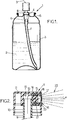
figure 11 est une vue de face de la paroi frontale de la buse de pulvérisation du dispositif, dans un quatrième mode de réalisation, les trous de cette paroi frontale étant représentés plus larges qu'en réalité, pour plus de clarté, - la
figure 12 est une vue en coupe développée, selon la ligne courbe XII-XII de lafigure 11 , - la
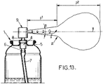
figure 13 est une vue similaire à lafigure 1 , illustrant le fonctionnement du quatrième mode de réalisation de l'invention.
- the
figure 1 is a vertical sectional view of a fluid spray device according to one embodiment of the invention, - the
figure 2 is a vertical sectional view of the pusher of the spraying device of FIG. 1, in a first embodiment of the invention, - the
figure 3 is a detailed sectional view of the spray nozzle fitted to the pusher of thefigure 2 , - the
figures 4 and 5 are vertical sectional views of the pusher of the spray device of the fig 1, in a second embodiment of the invention, the figures showing the spray nozzle respectively in a state of rest and in an actuation state, - the
figures 6 and 7 are similar views respectively tofigures 4 and 5 , in a variant of the second embodiment of the invention, - the
figures 8 and 9 are similar views respectively tofigures 2 and3 , in a third embodiment of the invention, - the
figure 10 is a view similar tofigure 9 , in a variant of the third embodiment of the invention, - the
figure 11 is a front view of the front wall of the spray nozzle of the device, in a fourth embodiment, the holes in this front wall being shown wider than in reality, for clarity, - the
figure 12 is a sectional view developed, along the curved line XII-XII of thefigure 11 , - the
figure 13 is a view similar tofigure 1 , illustrating the operation of the fourth embodiment of the invention.
Sur les différentes figures, les mêmes références désignent des éléments identiques ou similaires.In the various figures, the same references designate identical or similar elements.
La
Le dispositif de pulvérisation 1 comporte en outre un dispositif de distribution 4 qui est fixé de façon connue à un col 5 du réservoir 3 à l'extrémité supérieure dudit réservoir.The spraying device 1 further comprises a dispensing device 4 which is fixed so known to a
Le dispositif de distribution 4 peut par exemple être une pompe manuelle de pulvérisation ou encore une valve de pulvérisation, auquel cas le réservoir 3 est sous pression.The dispensing device 4 can for example be a manual spray pump or else a spray valve, in which case the reservoir 3 is under pressure.
Dans tous les cas, le dispositif de distribution 4 comporte une entrée 6 de produit fluide, orientée vers le bas, qui communique avec le fond du réservoir 3 par l'intermédiaire d'un tube plongeur 7, et une tige d'actionnement creuse 8 qui fait saillie vers le haut. Un bouton poussoir 9 est emboîté à l'extrémité supérieure de la tige d'actionnement 8, et sert à la fois à l'actionnement du dispositif de distribution 4 et à la sortie du produit fluide pulvérisé, sortie qui s'effectue au travers de la tige actionnement 8, selon la flèche 10 représentée sur la
On notera que le dispositif de distribution représenté en
Comme représenté sur la
Le poussoir 9 comporte une paroi supérieure 11 sensiblement horizontale et une jupe 12 sensiblement cylindrique et verticale, qui s'étend à partir de la périphérie de la paroi supérieure 11.The
Par ailleurs, le poussoir 9 comporte en outre un puits central 13 qui s'étend verticalement vers le bas à partir de la paroi supérieure 11, au centre de la paroi latérale 12. L'extrémité supérieure de la tige d'actionnement 8 est emboîtée dans le puits central 13.Furthermore, the
A l'extrémité supérieure du puits central 13 est ménagé un passage latéral 14 qui communique avec un logement de réception de buse 15 de forme sensiblement cylindrique, s'étendant sensiblement horizontalement selon un axe central X et débouchant vers l'extérieur du poussoir 9.At the upper end of the
Comme représenté sur les
- une paroi frontale perforée 17,
- et une paroi latérale annulaire 18 qui présente une forme cylindrique (de révolution ou non) qui s'étend selon l'axe X à l'intérieur du logement de buse 15, à partir de la périphérie de la paroi frontale 17.
- a perforated
front wall 17, - and an
annular side wall 18 which has a cylindrical shape (of revolution or not) which extends along the X axis inside thenozzle housing 15, from the periphery of thefront wall 17.
De façon connue en soi, la paroi latérale 18 de la buse de pulvérisation 16 peut comporter, à son extrémité opposée à la paroi frontale 17 un gaudron annulaire 19 qui fait saillie radialement vers l'extérieur et qui pénètre dans la matière du poussoir 9 pour ancrer la buse de pulvérisation 16 dans le logement de buse 15.In a manner known per se, the
La buse de pulvérisation 16 délimite, avec le poussoir 9, une chambre intérieure 20 qui communique avec le passage 14 susmentionné et qui reçoit le produit fluide à pulvériser lors de l'actionnement du dispositif de distribution 4. Eventuellement, comme on peut le voir sur la
Comme représenté plus en détail sur la
Plus généralement, le diamètre de chaque trou 22 ne diffère pas de la valeur moyenne des diamètres des différents trous 22 de plus de 20% et avantageusement, le diamètre de chaque trou 22 ne diffère pas de ladite valeur moyenne de plus de 10%.More generally, the diameter of each
Les trous 22 peuvent être de forme sensiblement cylindrique à section circulaire, mais ils pourraient le cas échéant présenter une section polygonale, par exemple carrée, auquel cas le diamètre susmentionné serait le diamètre équivalent du trou, c'est-à-dire le diamètre d'un trou circulaire présentant une section de même surface que le trou polygonal.The
Le diamètre des trous 22 peut être choisi en fonction du produit fluide à pulvériser, et par exemple :
- le diamètre moyen des trous 22 peut être compris entre 1 et 3 µm (micromètres) pour la pulvérisation de produits pharmaceutiques de traitement des poumons,
- le diamètre moyen des trous 22 peut être compris entre 3 et 10 µm pour la pulvérisation de produits pharmaceutiques de traitement de la trachée et des bronches,
- le diamètre moyen des trous 22 peut être compris entre 10 et 60 µm pour la pulvérisation de produits pharmaceutiques de traitement du nez, de la bouche ou de la gorge,
- le diamètre moyen des trous 22 peut être compris entre 50 et 100 µm pour la pulvérisation de produits pharmaceutiques de traitement de la peau ou pour la pulvérisation de produits de maquillage,
- le diamètre moyen des trous 22 peut être compris entre 15 et 60 µm pour la pulvérisation de produits de parfumerie,
- le diamètre moyen des trous 22 peut être compris entre 20 et 70 µm pour la pulvérisation de produits cosmétiques de soin de la peau,
- the average diameter of the
holes 22 can be between 1 and 3 µm (micrometers) for the spraying of pharmaceutical products for treating the lungs, - the average diameter of the
holes 22 may be between 3 and 10 μm for the spraying of pharmaceutical products for the treatment of the trachea and bronchi, - the average diameter of the
holes 22 may be between 10 and 60 μm for the spraying of pharmaceutical products for treating the nose, mouth or throat, - the average diameter of the
holes 22 may be between 50 and 100 μm for the spraying of pharmaceutical products for treating the skin or for the spraying of makeup products, - the average diameter of the
holes 22 may be between 15 and 60 µm for spraying products of perfumery, - the average diameter of the
holes 22 may be between 20 and 70 μm for spraying cosmetic skin care products,
La paroi frontale 17 peut présenter une forme bombée de concavité tournée vers l'intérieur, comme dans l'exemple représenté sur la
Par ailleurs, la paroi frontale 17 peut présenter une épaisseur e comprise généralement entre 0,08 et 1,5 mm, notamment entre 0,2 et 0,4 mm.Furthermore, the
Les trous 22 peuvent présenter une section constante, comme dans l'exemple représenté, mais les trous 22 pourraient le cas échéant présenter des parties évasées vers l'intérieur et/ou vers l'extérieur, auquel cas la longueur des trous 22 à prendre en compte serait la longueur dans laquelle ces trous présentent une section constante et le diamètre à prendre en compte serait le diamètre de la section minimale. La longueur des trous 22 dans leur partie à section constante, est généralement comprise entre 0,08 et 0,5 mm, avantageusement entre 0,08 et 0,3 mm, et plus avantageusement encore entre 0,08 et 0,2 mm, notamment égale à environ 0,1 mm.The
Comme représenté sur la
Dans un deuxième mode de réalisation représenté sur les
En particulier, dans l'état de repos, la paroi frontale 17b s'étend dans un plan perpendiculaire à l'axe central X. Et dans l'état d'actionnement, la paroi frontale 17b présente une convexité tournée vers l'extérieur de sorte, par exemple, à présenter une forme de calotte sphérique.In particular, in the rest state, the
Comme représenté sur les
Sur les
La réalisation de la paroi frontale 17b déformable élastiquement selon deuxième mode de réalisation peut être prévue de manière complémentaire ou indépendante de la réalisation précédemment décrite dans laquelle tous les trous 22 sont sensiblement de même diamètre, compris entre 1 et 100 µm, et le diamètre de chaque trou 22 ne diffère pas de la valeur moyenne des diamètres des différents trous 22 de plus de 20% et avantageusement.The realization of the elastically deformable
En variante représentée sur les
Comme représenté sur les
Le troisième mode de réalisation des
En variante représentée sur la
Par exemple, la paroi frontale 17a peut être réalisée en un matériau choisi parmi le silicium, le verre, les métaux et leurs alliages, les céramiques ou les polymères, tandis que la paroi latérale 18 est réalisée en matière plastique comme dans l'exemple précédent, ladite paroi latérale 18 pouvant être surmoulée sur le pourtour de la paroi frontale 17a.For example, the
Dans le mode de réalisation des
Par ailleurs, dans un autre mode de réalisation, la paroi frontale 17a peut être déformable. Par exemple, la paroi frontale 17a peut être réalisée sous la forme d'un complexe comprenant au moins une couche de polymère et éventuellement une couche de matériau métallique. Le complexe peut présenter une épaisseur comprise entre 0,025 et 0,120 mm.Furthermore, in another embodiment, the
A titre d'exemples non limitatifs, le complexe peut comprendre :
- une couche de polyester, d'une épaisseur de 0,025 mm, et une enduction thermocollante permettant le collage de la paroi frontale 17a sur la paroi latérale 18, ou
- une couche de polyester, d'une épaisseur de 0,025 mm, et une couche de polyéthylène, d'une épaisseur de 0,020 mm, permettant le soudage de la paroi frontale 17a sur la paroi latérale 18, ou
- une couche de polyester, d'une épaisseur de 0,025 mm, et une couche de polypropylène, d'une épaisseur de 0,020 mm, ou
- une couche de polyester, d'une épaisseur de 0,025 mm, une couche d'aluminium, d'une épaisseur de 0,008 mm, et une couche de polyéthylène, d'une épaisseur de 0,040 mm.
- a layer of polyester, with a thickness of 0.025 mm, and a heat-fusible coating allowing the
front wall 17a to be bonded to theside wall 18, or - a layer of polyester, with a thickness of 0.025 mm, and a layer of polyethylene, with a thickness of 0.020 mm, allowing the
front wall 17a to be welded to theside wall 18, or - one layer of polyester, 0.025 mm thick, and one layer of polypropylene, 0.020 mm thick, or
- a layer of polyester, with a thickness of 0.025 mm, a layer of aluminum, with a thickness of 0.008 mm, and a layer of polyethylene, with a thickness of 0.040 mm.
Dans le quatrième mode de réalisation de l'invention, représentée sur les
Du fait que les trous 22 sont tous inclinés dans le même sens angulaire 24 (
L'aérosol A présente une première partie b1, au voisinage de la buse de pulvérisation, dans laquelle les gouttelettes de liquide sont animées d'une grande vitesse d'avancement et qui est sensiblement conique ayant un angle d'ouverture α relativement élevé, par exemple de l'ordre de 20° ou plus.The aerosol A has a first part b1, in the vicinity of the spray nozzle, in which the liquid droplets are driven at a high speed of advance and which is substantially conical having a relatively high opening angle α, for example example of the order of 20 ° or more.
De plus, l'aérosol A présente une deuxième partie p2 formant un nuage dans lequel les gouttelettes de liquide ont une vitesse d'avancement moindre que dans la première partie p1. Grâce au mouvement tourbillonnaire des gouttelettes de liquide, la deuxième partie b2 de l'aérosol reste relativement symétrique par rapport à l'axe X.In addition, the aerosol A has a second part p2 forming a cloud in which the liquid droplets have a lower forward speed than in the first part p1. Thanks to the swirling movement of the liquid droplets, the second part b2 of the aerosol remains relatively symmetrical with respect to the X axis.
Dans ce mode de réalisation, avec une paroi frontale 17 comprenant une centaine de trous 22 de diamètre 3 µm ménagés dans une paroi 17 d'épaisseur 0,3 mm, avec une inclinaison des trous de l'ordre de 30° et avec une pression d'un liquide alcoolique de l'ordre de 0,5 bars à l'intérieur de la buse de pulvérisation, on obtient la pulvérisation d'un aérosol constitué de gouttelettes de diamètre 5 µm à 7 µm.In this embodiment, with a
Selon l'invention, la paroi frontale 17 est déformable élastiquement. A l'état de repos, les trous calibrés 22 peuvent alors être réalisés de manière simple avec un axe X2 qui s'étend dans un plan parallèle à l'axe central X de la buse de pulvérisation 16. La divergence de l'axe X2 des trous calibrés 22 peut être obtenue lors de l'actionnement du poussoir pour augmenter l'angle d'ouverture α de la première partie de l'aérosol A.According to the invention, the
Claims (17)
- Manual spraying device comprising:- a manually actuatable pusher (9), said pusher comprising a spraying nozzle (16), said spraying nozzle comprising an inner chamber (20) adapted to receive a pressurised, non-gaseous fluid product, and delimited outwards by a perforated front wall (17),- a reservoir (3) of fluid product to be sprayed,- and a dispensing device (4), mechanically actuatable by the pusher and adapted to transfer the fluid product from the reservoir (3) to the inner chamber (20) of the nozzle,- the front wall (17) comprises a plurality of calibrated holes (22) each having a diameter comprised between 1 and 100µm, the diameter of each hole not differing from an average of the diameters of the different holes by more than 20%,- the front wall (17b; 17c) is elastically deformable between a rest state, wherein said front wall (17b; 17c) is flat, and an actuation state when the pressurised fluid product is transferred into the inner chamber (20), wherein said front wall (17b; 17c) has a convexity rotated outwards.
- Spraying device according to claim 1, wherein the front wall (17b; 17c) in the actuation state has a spherical cap shape.
- Spraying device according to any one of claims 1 to 2, wherein the front wall (17) is integral with a peripheral side wall (18; 18a) which extends longitudinally along a central axis (X) substantially perpendicular to said front wall (17).
- Spraying device according to claim 3, wherein the front wall (17) is formed of one single part with the side wall (18; 18a).
- Spraying device according to claim 4, wherein the side wall (18a) is formed of one single part with the pusher (9), and the front wall (17b; 17c) has a thickness (e) comprised between 0.10 and 0.20mm.
- Spraying device according to claim 4, wherein the side wall (18) is a part separate from the pusher, integral with said pusher (9), and the front wall (17b; 17c) has a thickness comprised between 0.05 and 0.10mm.
- Spraying device according to claim 3, wherein the front wall (17a) is a part separate from the side wall (18; 18a), integral with said side wall (18; 18a).
- Spraying device according to claim 7, wherein the front wall (17a) is made of a material selected from among silicon, glass, metals and their alloys, ceramics, polymers.
- Spraying device according to claim 7 or claim 8, wherein the side wall (18) is made of plastic material and is overmoulded around the front wall.
- Spraying device according to claim 7, wherein the front wall (17a) is made in the form of a complex comprising at least one polymer layer.
- Spraying device according to claim 10, wherein the complex comprises a polyester layer.
- Spraying device according to claim 11, wherein the complex further comprises a coating of thermobonding material, the front wall (17a) being glued onto the side wall (18; 18a).
- Spraying device according to claim 11, wherein the complex further comprises at least one polymer layer selected from among polyethylene and polypropylene, the front wall (17a) being welded onto the side wall (18; 18a).
- Spraying device according to any one of claims 10 to 13, wherein the complex further comprises at least one metal material layer.
- Spraying device according to any one of claims 10 to 13, wherein the complex has a thickness comprised between 0.025 and 0.120mm.
- Spraying device according to any one of claims 1 to 15, wherein the diameter of each hole (22) of the front wall does not differ from said average by more than 10%.
- Spraying device according to any one of claims 1 to 16, wherein the holes (22) of the front wall (17) are distributed about a centre (O), each hole (22) extends along an axis (X2) inclined with respect to the normal (X1) to said front wall at the level of said hole (22), said axis (X2) and said normal (X1) defining a plane substantially tangent to a circle (C) centred on said central point (O) and passing through the hole (22), the axes (X2) of all the holes having an inclination (Y) with respect to the corresponding normal (X1), and said axes (X2) of all the holes (22) all being inclined in the direction of one same angular direction (24) about said central point (O), so as to generate a swirling aerosol (A) when the fluid product is sprayed by said nozzle.
Applications Claiming Priority (3)
| Application Number | Priority Date | Filing Date | Title |
|---|---|---|---|
| FR0606259A FR2903328B1 (en) | 2006-07-10 | 2006-07-10 | SPRAY NOZZLE, SPRAY DEVICE AND USE THEREOF. |
| FR0700485A FR2903329B3 (en) | 2006-07-10 | 2007-01-24 | SPRAY NOZZLE, SPRAY DEVICE AND USE THEREOF. |
| EP07111772.5A EP1878507B2 (en) | 2006-07-10 | 2007-07-04 | Spraying device and use of same |
Related Parent Applications (2)
| Application Number | Title | Priority Date | Filing Date |
|---|---|---|---|
| EP07111772.5A Division-Into EP1878507B2 (en) | 2006-07-10 | 2007-07-04 | Spraying device and use of same |
| EP07111772.5A Division EP1878507B2 (en) | 2006-07-10 | 2007-07-04 | Spraying device and use of same |
Publications (2)
| Publication Number | Publication Date |
|---|---|
| EP3246096A1 EP3246096A1 (en) | 2017-11-22 |
| EP3246096B1 true EP3246096B1 (en) | 2021-09-08 |
Family
ID=38510412
Family Applications (2)
| Application Number | Title | Priority Date | Filing Date |
|---|---|---|---|
| EP07111772.5A Active EP1878507B2 (en) | 2006-07-10 | 2007-07-04 | Spraying device and use of same |
| EP17175982.2A Active EP3246096B1 (en) | 2006-07-10 | 2007-07-04 | Spraying device and use of same |
Family Applications Before (1)
| Application Number | Title | Priority Date | Filing Date |
|---|---|---|---|
| EP07111772.5A Active EP1878507B2 (en) | 2006-07-10 | 2007-07-04 | Spraying device and use of same |
Country Status (5)
| Country | Link |
|---|---|
| US (1) | US7748647B2 (en) |
| EP (2) | EP1878507B2 (en) |
| BR (1) | BRPI0702942B1 (en) |
| FR (1) | FR2903329B3 (en) |
| RU (1) | RU2007125994A (en) |
Families Citing this family (31)
| Publication number | Priority date | Publication date | Assignee | Title |
|---|---|---|---|---|
| FR2903329B3 (en) † | 2006-07-10 | 2008-10-03 | Rexam Dispensing Systems Sas | SPRAY NOZZLE, SPRAY DEVICE AND USE THEREOF. |
| DE102007049614B4 (en) * | 2007-03-15 | 2015-03-05 | Aptar Dortmund Gmbh | dispenser |
| ES2436002T3 (en) | 2008-06-20 | 2013-12-26 | Aptar Dortmund Gmbh | Distribution device |
| DE102008038654B4 (en) | 2008-08-12 | 2019-09-19 | Aptar Dortmund Gmbh | Dispensing head with swiveling valve element |
| GB2466631A (en) * | 2008-10-21 | 2010-07-07 | Philip Alan Durrant | A spray device for atomising fluids having at least three nozzles with a restriction |
| DE102009030627B4 (en) * | 2009-06-25 | 2020-03-12 | Aptar Dortmund Gmbh | Valve and dispenser |
| FR2971772B1 (en) * | 2011-02-17 | 2013-03-22 | Valois Sas | DEVICE FOR DISPENSING FLUID PRODUCT. |
| DE102013202531B3 (en) * | 2013-02-16 | 2014-05-28 | Aptar Radolfzell Gmbh | Dispenser for the discharge of liquids |
| CN106573134B (en) * | 2014-06-20 | 2021-04-06 | 美德斯普瑞公司 | Spraying device and method for producing a spraying device and associated device |
| EP3095522A1 (en) * | 2015-05-20 | 2016-11-23 | Aptar Radolfzell GmbH | Inhalation device, inhalation device set and associated nozzle plate |
| JP6634255B2 (en) * | 2015-09-30 | 2020-01-22 | 株式会社吉野工業所 | Dispenser with nozzle tip |
| WO2017095219A1 (en) * | 2015-12-04 | 2017-06-08 | Medspray Bv | Spray device and spray nozzle body |
| RU2710563C2 (en) * | 2015-12-04 | 2019-12-27 | Медспрай Бв | Liquid sprayer |
| FR3048236B1 (en) * | 2016-02-29 | 2019-07-12 | Albea Le Treport | PRODUCT DELIVERY SYSTEM FOR BOTTLE |
| AU2017306411B2 (en) * | 2016-08-03 | 2022-03-31 | Scentbridge Holdings, Llc | Method and system of a networked scent diffusion device |
| WO2019106321A1 (en) | 2017-12-01 | 2019-06-06 | Aptar France Sas | Fluid-product dispensing head |
| FR3059573B1 (en) * | 2016-12-02 | 2019-01-25 | Aptar France Sas | HEAD OF DISTRIBUTION OF FLUID PRODUCT |
| WO2019038500A1 (en) | 2017-08-24 | 2019-02-28 | Safran Aircraft Engines | Blade for a turbomachine and method for the manufacture thereof |
| BR112020009544B1 (en) | 2017-12-01 | 2023-01-24 | Aptar France Sas | FLUID DISPENSER HEAD, MANUFACTURING METHOD FOR FABRICATING A SPRAY WALL AND FLUID DISPENSER |
| EP3717137A1 (en) | 2017-12-01 | 2020-10-07 | Aptar France SAS | Fluid product dispensing head |
| EP3717136A1 (en) | 2017-12-01 | 2020-10-07 | APTAR France SAS | Method for producing a distribution wall |
| US11305142B2 (en) * | 2018-01-12 | 2022-04-19 | Carrier Corporation | End cap agent nozzle |
| US11691161B2 (en) | 2018-05-02 | 2023-07-04 | Innovative Product Brands, Inc. | Sprayer with a six-hole spray pattern |
| EP3569318A1 (en) | 2018-05-16 | 2019-11-20 | Medspray B.V. | Spray device for generating a micro-jet spray |
| NL2021704B1 (en) | 2018-09-25 | 2020-05-07 | Medspray B V | Spray device, nozzle unit and nozzle body |
| FR3095968B1 (en) | 2019-05-14 | 2021-10-01 | Aptar France Sas | Fluid dispenser device |
| FR3096090B1 (en) | 2019-05-14 | 2022-10-28 | Aptar France Sas | High pressure pre-compression pump |
| FR3096089B1 (en) | 2019-05-14 | 2022-08-05 | Aptar France Sas | Method of assembling a high pressure pre-compression pump |
| FR3098137B1 (en) | 2019-07-02 | 2022-07-15 | Aptar France Sas | Method of manufacturing a distribution wall |
| CN114728298B (en) | 2019-11-22 | 2023-11-10 | 阿普塔尔法国简易股份公司 | Method for producing a dispensing wall |
| CN111701779B (en) * | 2020-06-19 | 2021-11-26 | 湖南云天雾化科技有限公司 | Self-spraying atomizer and cooling atomizing head |
Family Cites Families (38)
| Publication number | Priority date | Publication date | Assignee | Title |
|---|---|---|---|---|
| US1869809A (en) † | 1930-12-24 | 1932-08-02 | John M Hewlett | Liquid atomizing device |
| US2273830A (en) † | 1940-11-29 | 1942-02-24 | Ralph C Brierly | Method of making nozzle sprayer plates |
| US2493209A (en) † | 1949-01-25 | 1950-01-03 | Burgess Battery Co | Spray or atomizer nozzle |
| US2767023A (en) † | 1956-03-27 | 1956-10-16 | Risdon Mfg Co | Spray nozzles |
| US2874001A (en) | 1956-06-21 | 1959-02-17 | Ernest C Webb | Shower head |
| US3504862A (en) † | 1968-01-05 | 1970-04-07 | Gillette Co | Dispensing device |
| FR2284533A1 (en) † | 1974-09-13 | 1976-04-09 | Blendax Werke Schneider Co | Collapsible (esp. aluminium or aluminium alloy)tube - has plastics captive closure that need not be screwed on and off |
| DE2925435A1 (en) † | 1979-06-23 | 1981-01-22 | Hans Ing Grad Grothoff | Spray head for pressurised liq. has opening for insert - with outer axial grooves forming nozzle ducts with wall of opening |
| JP2922935B2 (en) † | 1989-08-11 | 1999-07-26 | 東興薬品工業株式会社 | Disposable adapter for nasal spray container for viscous liquid |
| GB8921745D0 (en) † | 1989-09-27 | 1989-11-08 | Aerosol Inventions Dev | Pressurised dispensers |
| US5152456A (en) † | 1989-12-12 | 1992-10-06 | Bespak, Plc | Dispensing apparatus having a perforate outlet member and a vibrating device |
| US5518179A (en) † | 1991-12-04 | 1996-05-21 | The Technology Partnership Limited | Fluid droplets production apparatus and method |
| FR2702196B1 (en) * | 1993-03-05 | 1995-05-12 | Oreal | Pressure foam dispenser. |
| US5435884A (en) † | 1993-09-30 | 1995-07-25 | Parker-Hannifin Corporation | Spray nozzle and method of manufacturing same |
| US5642860A (en) † | 1995-07-07 | 1997-07-01 | The Procter & Gamble Company | Pump sprayer for viscous or solids laden liquids |
| FR2756502B1 (en) † | 1996-12-03 | 1999-01-22 | Oreal | NOZZLE FOR A DEVICE FOR SPRAYING A LIQUID AND SPRAYING DEVICE PROVIDED WITH SUCH A NOZZLE |
| US5868003A (en) | 1997-07-14 | 1999-02-09 | Praxair Technology, Inc. | Apparatus for producing fine snow particles from a flow liquid carbon dioxide |
| DE1149602T1 (en) † | 1997-11-19 | 2002-04-04 | Microflow Eng Sa | Spray device for an inhaler suitable for respiratory therapy |
| FR2773783B1 (en) † | 1998-01-22 | 2000-03-24 | Rexam Smt | SELF-SHUTTERING MANUAL DISPENSER |
| FR2774077B1 (en) † | 1998-01-23 | 2000-04-07 | Oreal | VALVE WITH OUTLET FLOW REGULATION, AND CONTAINER PROVIDED WITH SUCH A VALVE |
| FR2785222B1 (en) † | 1998-11-02 | 2001-01-19 | Valois Sa | METHOD FOR MANUFACTURING A SHUTTER, PUSH-BUTTON AND DISPENSING HEAD INCORPORATING SUCH A SHUTTER |
| FR2790742B1 (en) † | 1999-03-10 | 2001-05-04 | Oreal | UNIT FOR PACKAGING AND DISTRIBUTION UNDER PRESSURE OF A PRODUCT, ESPECIALLY COSMETIC |
| FR2793222B1 (en) † | 1999-05-05 | 2001-07-06 | Oreal | DISTRIBUTION HEAD AND CONTAINER THUS EQUIPPED |
| TR200402489T4 (en) * | 2000-07-05 | 2004-12-21 | Unilever N.V. | Spray head. |
| NL1016030C1 (en) † | 2000-08-28 | 2002-03-01 | Aquamarijn Holding B V | Spraying device with a nozzle plate, a nozzle plate, as well as methods for manufacturing and applying such a nozzle plate. |
| JP2002186882A (en) * | 2000-12-19 | 2002-07-02 | Kyowa Kogyo Kk | Nozzle assembly |
| US6732943B2 (en) * | 2001-04-05 | 2004-05-11 | Aradigm Corporation | Method of generating uniform pores in thin polymer films |
| DE10143350A1 (en) * | 2001-09-04 | 2003-03-20 | Boehringer Ingelheim Int | Locking mechanism for a miniaturized high pressure generator |
| DE50208993D1 (en) † | 2001-09-21 | 2007-02-01 | Pfeiffer Erich Gmbh & Co Kg | Dosing device with a media storage and pumping device therefor |
| FR2831522B1 (en) † | 2001-10-30 | 2004-08-27 | Valois Sa | FLUID PRODUCT DISPENSER |
| FR2832988B1 (en) † | 2001-12-04 | 2004-11-19 | Valois Sa | FLUID PRODUCT DISPENSER |
| FR2836401B1 (en) | 2002-02-26 | 2004-12-17 | Rieter Perfojet | DEVICE FOR REGULAR SPRAYING OF WATER JETS APPLYING IN PARTICULAR TO A NONWOVEN BINDING INSTALLATION |
| DE20212798U1 (en) | 2002-08-21 | 2002-11-28 | Dirschnabel Hans Peter | Nozzle with micro nozzle openings |
| FR2851483B1 (en) † | 2003-02-20 | 2005-05-13 | Valois Sas | HEAD OF DISTRIBUTION |
| NL1026752C2 (en) | 2004-07-30 | 2006-02-02 | Stork Veco Bv | Atomizing plate for atomizing a fluid, method for manufacturing an atomizing plate and application of an atomizing plate. |
| US7654419B2 (en) | 2004-09-17 | 2010-02-02 | Meadwestvaco Calmar, Inc. | Dispenser having elastomer discharge valve |
| DE102005010173B4 (en) | 2005-03-05 | 2006-11-16 | Aero Pump GmbH, Zerstäuberpumpen | Discharge hood for a sprayer for spraying a high-viscosity liquid |
| FR2903329B3 (en) † | 2006-07-10 | 2008-10-03 | Rexam Dispensing Systems Sas | SPRAY NOZZLE, SPRAY DEVICE AND USE THEREOF. |
-
2007
- 2007-01-24 FR FR0700485A patent/FR2903329B3/en not_active Expired - Lifetime
- 2007-07-04 EP EP07111772.5A patent/EP1878507B2/en active Active
- 2007-07-04 EP EP17175982.2A patent/EP3246096B1/en active Active
- 2007-07-09 RU RU2007125994/12A patent/RU2007125994A/en not_active Application Discontinuation
- 2007-07-09 BR BRPI0702942A patent/BRPI0702942B1/en active IP Right Grant
- 2007-07-10 US US11/775,431 patent/US7748647B2/en active Active
Also Published As
| Publication number | Publication date |
|---|---|
| BRPI0702942B1 (en) | 2019-01-08 |
| EP1878507B2 (en) | 2023-08-30 |
| EP1878507B1 (en) | 2017-09-06 |
| BRPI0702942A (en) | 2008-02-26 |
| EP3246096A1 (en) | 2017-11-22 |
| US20080006719A1 (en) | 2008-01-10 |
| EP1878507A2 (en) | 2008-01-16 |
| FR2903329A1 (en) | 2008-01-11 |
| RU2007125994A (en) | 2009-01-20 |
| US7748647B2 (en) | 2010-07-06 |
| FR2903329B3 (en) | 2008-10-03 |
| EP1878507A3 (en) | 2010-03-03 |
| BRPI0702942A8 (en) | 2015-04-07 |
Similar Documents
| Publication | Publication Date | Title |
|---|---|---|
| EP3246096B1 (en) | Spraying device and use of same | |
| FR2903328A1 (en) | Manual spraying device for spraying e.g. pharmaceutical product, has set of calibrated holes, where diameter of each hole ranges between specific micrometers and does not differ from mean of diameters of other holes by specific percentage | |
| EP2496361B2 (en) | Pushbutton for a system for dispensing a pressurized substance | |
| EP0655208B1 (en) | Applicator device for liquids | |
| EP0952090B1 (en) | Dosing tip | |
| EP3231516B1 (en) | Spray nozzle, in particular for a system for dispensing a pressurized fluid provided with a pushbutton, and dispensing system comprising such a nozzle | |
| FR2985201A1 (en) | HOLLOW DISTRIBUTION HEAD | |
| FR2985202A1 (en) | HEAD OF DISTRIBUTION | |
| WO1996021512A1 (en) | Spray nozzle | |
| FR2826344A1 (en) | DEVICE FOR SPRAYING A PRODUCT, ESPECIALLY IN THE FORM OF A SAMPLE DOSE | |
| EP2606980B1 (en) | Push button for a system for pressurised product distribution | |
| FR2817244A1 (en) | IMPROVED DEVICE FOR PACKAGING AND DOSED DISPENSING OF A LIQUID PRODUCT | |
| EP2119508B1 (en) | Push button for convergent distribution channels | |
| WO2003084669A1 (en) | Spray nozzle | |
| EP0669167B1 (en) | Assembly for the quasi-continuous distribution of liquids comprising a pump and use of such an assembly for spraying a hairspray | |
| WO2003061839A1 (en) | Atomisation nozzle with reduced diameter | |
| EP2233211B1 (en) | Push button for a pressurised liquid distribution system | |
| FR2819493A1 (en) | CONTAINER DISPENSING CONSTANT QUANTITIES OF PRODUCT UNTIL THE CONTAINER IS ALMOST COMPLETELY EMPTY | |
| EP2353726B1 (en) | Push button for a system for pressurised product distribution | |
| WO2012143664A1 (en) | Device for dispensing liquid product provided with a flow reduction member | |
| FR3078271A1 (en) | DISTRIBUTION HEAD WITH TURNED SHRUB CHAMBER FOR A DISTRIBUTION SYSTEM | |
| EP2279795B1 (en) | System for dispensing a fluid product | |
| FR3032895B1 (en) | PUSH BUTTON FOR A PRESSURE DISTRIBUTION SYSTEM OF A PRODUCT | |
| FR3047235A1 (en) | PRESSURIZED CONTAINER WITH HOLLOW HEAD AND ADDITIONAL GAS VALVE | |
| WO2018041594A1 (en) | Pressurised fluid dispensing head and aerosol can or manual pump comprising such a dispensing head |
Legal Events
| Date | Code | Title | Description |
|---|---|---|---|
| PUAI | Public reference made under article 153(3) epc to a published international application that has entered the european phase |
Free format text: ORIGINAL CODE: 0009012 |
|
| STAA | Information on the status of an ep patent application or granted ep patent |
Free format text: STATUS: THE APPLICATION HAS BEEN PUBLISHED |
|
| AC | Divisional application: reference to earlier application |
Ref document number: 1878507 Country of ref document: EP Kind code of ref document: P |
|
| AK | Designated contracting states |
Kind code of ref document: A1 Designated state(s): DE FR GB |
|
| STAA | Information on the status of an ep patent application or granted ep patent |
Free format text: STATUS: REQUEST FOR EXAMINATION WAS MADE |
|
| 17P | Request for examination filed |
Effective date: 20180522 |
|
| RBV | Designated contracting states (corrected) |
Designated state(s): DE FR GB |
|
| STAA | Information on the status of an ep patent application or granted ep patent |
Free format text: STATUS: EXAMINATION IS IN PROGRESS |
|
| 17Q | First examination report despatched |
Effective date: 20190313 |
|
| STAA | Information on the status of an ep patent application or granted ep patent |
Free format text: STATUS: EXAMINATION IS IN PROGRESS |
|
| GRAP | Despatch of communication of intention to grant a patent |
Free format text: ORIGINAL CODE: EPIDOSNIGR1 |
|
| STAA | Information on the status of an ep patent application or granted ep patent |
Free format text: STATUS: GRANT OF PATENT IS INTENDED |
|
| INTG | Intention to grant announced |
Effective date: 20210325 |
|
| GRAJ | Information related to disapproval of communication of intention to grant by the applicant or resumption of examination proceedings by the epo deleted |
Free format text: ORIGINAL CODE: EPIDOSDIGR1 |
|
| STAA | Information on the status of an ep patent application or granted ep patent |
Free format text: STATUS: EXAMINATION IS IN PROGRESS |
|
| GRAS | Grant fee paid |
Free format text: ORIGINAL CODE: EPIDOSNIGR3 |
|
| STAA | Information on the status of an ep patent application or granted ep patent |
Free format text: STATUS: GRANT OF PATENT IS INTENDED |
|
| GRAP | Despatch of communication of intention to grant a patent |
Free format text: ORIGINAL CODE: EPIDOSNIGR1 |
|
| INTC | Intention to grant announced (deleted) | ||
| INTG | Intention to grant announced |
Effective date: 20210708 |
|
| GRAA | (expected) grant |
Free format text: ORIGINAL CODE: 0009210 |
|
| STAA | Information on the status of an ep patent application or granted ep patent |
Free format text: STATUS: THE PATENT HAS BEEN GRANTED |
|
| AC | Divisional application: reference to earlier application |
Ref document number: 1878507 Country of ref document: EP Kind code of ref document: P |
|
| AK | Designated contracting states |
Kind code of ref document: B1 Designated state(s): DE FR GB |
|
| REG | Reference to a national code |
Ref country code: GB Ref legal event code: FG4D Free format text: NOT ENGLISH |
|
| REG | Reference to a national code |
Ref country code: DE Ref legal event code: R096 Ref document number: 602007061299 Country of ref document: DE |
|
| REG | Reference to a national code |
Ref country code: DE Ref legal event code: R026 Ref document number: 602007061299 Country of ref document: DE |
|
| PLBI | Opposition filed |
Free format text: ORIGINAL CODE: 0009260 |
|
| 26 | Opposition filed |
Opponent name: APTAR FRANCE SAS Effective date: 20220607 |
|
| PLAB | Opposition data, opponent's data or that of the opponent's representative modified |
Free format text: ORIGINAL CODE: 0009299OPPO |
|
| PLAX | Notice of opposition and request to file observation + time limit sent |
Free format text: ORIGINAL CODE: EPIDOSNOBS2 |
|
| R26 | Opposition filed (corrected) |
Opponent name: APTAR FRANCE SAS Effective date: 20220607 |
|
| PLBB | Reply of patent proprietor to notice(s) of opposition received |
Free format text: ORIGINAL CODE: EPIDOSNOBS3 |
|
| P01 | Opt-out of the competence of the unified patent court (upc) registered |
Effective date: 20230607 |
|
| PGFP | Annual fee paid to national office [announced via postgrant information from national office to epo] |
Ref country code: GB Payment date: 20230727 Year of fee payment: 17 |
|
| PGFP | Annual fee paid to national office [announced via postgrant information from national office to epo] |
Ref country code: FR Payment date: 20230725 Year of fee payment: 17 Ref country code: DE Payment date: 20230727 Year of fee payment: 17 |