EP3245702B1 - Method for operating an electrical load or generator on a subscriber network and a switching matrix - Google Patents
Method for operating an electrical load or generator on a subscriber network and a switching matrix Download PDFInfo
- Publication number
- EP3245702B1 EP3245702B1 EP15794540.3A EP15794540A EP3245702B1 EP 3245702 B1 EP3245702 B1 EP 3245702B1 EP 15794540 A EP15794540 A EP 15794540A EP 3245702 B1 EP3245702 B1 EP 3245702B1
- Authority
- EP
- European Patent Office
- Prior art keywords
- switching matrix
- phases
- subscriber network
- subscriber
- phase
- Prior art date
- Legal status (The legal status is an assumption and is not a legal conclusion. Google has not performed a legal analysis and makes no representation as to the accuracy of the status listed.)
- Active
Links
- 239000011159 matrix material Substances 0.000 title claims description 135
- 238000000034 method Methods 0.000 title claims description 17
- 238000005259 measurement Methods 0.000 claims description 37
- 238000004891 communication Methods 0.000 claims description 10
- 238000012546 transfer Methods 0.000 description 16
- 230000007935 neutral effect Effects 0.000 description 15
- 239000004020 conductor Substances 0.000 description 10
- 238000010586 diagram Methods 0.000 description 10
- 230000006870 function Effects 0.000 description 4
- 238000013459 approach Methods 0.000 description 2
- 230000001681 protective effect Effects 0.000 description 2
- 239000004065 semiconductor Substances 0.000 description 2
- 230000001174 ascending effect Effects 0.000 description 1
- 230000001419 dependent effect Effects 0.000 description 1
- 238000006073 displacement reaction Methods 0.000 description 1
- 230000005611 electricity Effects 0.000 description 1
- 238000010438 heat treatment Methods 0.000 description 1
- 238000012545 processing Methods 0.000 description 1
- 230000001105 regulatory effect Effects 0.000 description 1
- 230000003068 static effect Effects 0.000 description 1
Images


Classifications
-
- H—ELECTRICITY
- H02—GENERATION; CONVERSION OR DISTRIBUTION OF ELECTRIC POWER
- H02J—CIRCUIT ARRANGEMENTS OR SYSTEMS FOR SUPPLYING OR DISTRIBUTING ELECTRIC POWER; SYSTEMS FOR STORING ELECTRIC ENERGY
- H02J3/00—Circuit arrangements for ac mains or ac distribution networks
- H02J3/26—Arrangements for eliminating or reducing asymmetry in polyphase networks
-
- H—ELECTRICITY
- H02—GENERATION; CONVERSION OR DISTRIBUTION OF ELECTRIC POWER
- H02J—CIRCUIT ARRANGEMENTS OR SYSTEMS FOR SUPPLYING OR DISTRIBUTING ELECTRIC POWER; SYSTEMS FOR STORING ELECTRIC ENERGY
- H02J3/00—Circuit arrangements for ac mains or ac distribution networks
- H02J3/007—Arrangements for selectively connecting the load or loads to one or several among a plurality of power lines or power sources
-
- H—ELECTRICITY
- H02—GENERATION; CONVERSION OR DISTRIBUTION OF ELECTRIC POWER
- H02J—CIRCUIT ARRANGEMENTS OR SYSTEMS FOR SUPPLYING OR DISTRIBUTING ELECTRIC POWER; SYSTEMS FOR STORING ELECTRIC ENERGY
- H02J3/00—Circuit arrangements for ac mains or ac distribution networks
- H02J3/12—Circuit arrangements for ac mains or ac distribution networks for adjusting voltage in ac networks by changing a characteristic of the network load
- H02J3/14—Circuit arrangements for ac mains or ac distribution networks for adjusting voltage in ac networks by changing a characteristic of the network load by switching loads on to, or off from, network, e.g. progressively balanced loading
-
- H—ELECTRICITY
- H02—GENERATION; CONVERSION OR DISTRIBUTION OF ELECTRIC POWER
- H02J—CIRCUIT ARRANGEMENTS OR SYSTEMS FOR SUPPLYING OR DISTRIBUTING ELECTRIC POWER; SYSTEMS FOR STORING ELECTRIC ENERGY
- H02J13/00—Circuit arrangements for providing remote indication of network conditions, e.g. an instantaneous record of the open or closed condition of each circuitbreaker in the network; Circuit arrangements for providing remote control of switching means in a power distribution network, e.g. switching in and out of current consumers by using a pulse code signal carried by the network
- H02J13/00004—Circuit arrangements for providing remote indication of network conditions, e.g. an instantaneous record of the open or closed condition of each circuitbreaker in the network; Circuit arrangements for providing remote control of switching means in a power distribution network, e.g. switching in and out of current consumers by using a pulse code signal carried by the network characterised by the power network being locally controlled
-
- H—ELECTRICITY
- H02—GENERATION; CONVERSION OR DISTRIBUTION OF ELECTRIC POWER
- H02J—CIRCUIT ARRANGEMENTS OR SYSTEMS FOR SUPPLYING OR DISTRIBUTING ELECTRIC POWER; SYSTEMS FOR STORING ELECTRIC ENERGY
- H02J2310/00—The network for supplying or distributing electric power characterised by its spatial reach or by the load
- H02J2310/10—The network having a local or delimited stationary reach
- H02J2310/12—The local stationary network supplying a household or a building
- H02J2310/14—The load or loads being home appliances
-
- Y—GENERAL TAGGING OF NEW TECHNOLOGICAL DEVELOPMENTS; GENERAL TAGGING OF CROSS-SECTIONAL TECHNOLOGIES SPANNING OVER SEVERAL SECTIONS OF THE IPC; TECHNICAL SUBJECTS COVERED BY FORMER USPC CROSS-REFERENCE ART COLLECTIONS [XRACs] AND DIGESTS
- Y02—TECHNOLOGIES OR APPLICATIONS FOR MITIGATION OR ADAPTATION AGAINST CLIMATE CHANGE
- Y02B—CLIMATE CHANGE MITIGATION TECHNOLOGIES RELATED TO BUILDINGS, e.g. HOUSING, HOUSE APPLIANCES OR RELATED END-USER APPLICATIONS
- Y02B70/00—Technologies for an efficient end-user side electric power management and consumption
- Y02B70/30—Systems integrating technologies related to power network operation and communication or information technologies for improving the carbon footprint of the management of residential or tertiary loads, i.e. smart grids as climate change mitigation technology in the buildings sector, including also the last stages of power distribution and the control, monitoring or operating management systems at local level
- Y02B70/3225—Demand response systems, e.g. load shedding, peak shaving
-
- Y—GENERAL TAGGING OF NEW TECHNOLOGICAL DEVELOPMENTS; GENERAL TAGGING OF CROSS-SECTIONAL TECHNOLOGIES SPANNING OVER SEVERAL SECTIONS OF THE IPC; TECHNICAL SUBJECTS COVERED BY FORMER USPC CROSS-REFERENCE ART COLLECTIONS [XRACs] AND DIGESTS
- Y02—TECHNOLOGIES OR APPLICATIONS FOR MITIGATION OR ADAPTATION AGAINST CLIMATE CHANGE
- Y02E—REDUCTION OF GREENHOUSE GAS [GHG] EMISSIONS, RELATED TO ENERGY GENERATION, TRANSMISSION OR DISTRIBUTION
- Y02E40/00—Technologies for an efficient electrical power generation, transmission or distribution
- Y02E40/50—Arrangements for eliminating or reducing asymmetry in polyphase networks
-
- Y—GENERAL TAGGING OF NEW TECHNOLOGICAL DEVELOPMENTS; GENERAL TAGGING OF CROSS-SECTIONAL TECHNOLOGIES SPANNING OVER SEVERAL SECTIONS OF THE IPC; TECHNICAL SUBJECTS COVERED BY FORMER USPC CROSS-REFERENCE ART COLLECTIONS [XRACs] AND DIGESTS
- Y04—INFORMATION OR COMMUNICATION TECHNOLOGIES HAVING AN IMPACT ON OTHER TECHNOLOGY AREAS
- Y04S—SYSTEMS INTEGRATING TECHNOLOGIES RELATED TO POWER NETWORK OPERATION, COMMUNICATION OR INFORMATION TECHNOLOGIES FOR IMPROVING THE ELECTRICAL POWER GENERATION, TRANSMISSION, DISTRIBUTION, MANAGEMENT OR USAGE, i.e. SMART GRIDS
- Y04S20/00—Management or operation of end-user stationary applications or the last stages of power distribution; Controlling, monitoring or operating thereof
- Y04S20/20—End-user application control systems
- Y04S20/222—Demand response systems, e.g. load shedding, peak shaving
-
- Y—GENERAL TAGGING OF NEW TECHNOLOGICAL DEVELOPMENTS; GENERAL TAGGING OF CROSS-SECTIONAL TECHNOLOGIES SPANNING OVER SEVERAL SECTIONS OF THE IPC; TECHNICAL SUBJECTS COVERED BY FORMER USPC CROSS-REFERENCE ART COLLECTIONS [XRACs] AND DIGESTS
- Y04—INFORMATION OR COMMUNICATION TECHNOLOGIES HAVING AN IMPACT ON OTHER TECHNOLOGY AREAS
- Y04S—SYSTEMS INTEGRATING TECHNOLOGIES RELATED TO POWER NETWORK OPERATION, COMMUNICATION OR INFORMATION TECHNOLOGIES FOR IMPROVING THE ELECTRICAL POWER GENERATION, TRANSMISSION, DISTRIBUTION, MANAGEMENT OR USAGE, i.e. SMART GRIDS
- Y04S20/00—Management or operation of end-user stationary applications or the last stages of power distribution; Controlling, monitoring or operating thereof
- Y04S20/20—End-user application control systems
- Y04S20/242—Home appliances
Definitions
- the subject matter relates to a method, a device and a switching matrix for operating electrical consumers or generators on a subscriber network.
- a multi-phase network in particular a three-phase network, for example, a three-phase network
- the power consumption of a subscriber network per phase is limited in order to prevent a difference in an electrical quantity between the phases from exceeding a maximum value. Unbalances at the subscriber result in increased losses in the subscriber network which are to be avoided.
- an unequal load of the subscriber network at the phases leads to a zero offset / neutral point shift. To compensate for these equalizing currents in the neutral are necessary, causing unnecessary losses.
- the load distribution in the three-phase network is essentially the same due to a statistical distribution.
- the subscriber network is connected by the electrician to the three phases L1, L2 and L3 of the distribution network.
- a connection of the participants of the household to one of the three phases L1, L2, L3 takes place essentially at random, namely, depending on which phase the electrician has connected the respective supply line in the distribution box. Because of this statistical Distribution of a large number of low-performance participants is assumed that the imbalance in the subscriber network and thus in the distribution network, here the low voltage level, irrelevant and there is a more or less uniform phase utilization.
- single-phase connected photovoltaic devices may only feed a maximum of 4.6 kVA into this phase into the distribution network.
- Single-phase charging electric vehicles may not receive more than 4.6 kVA from this single phase.
- the technical connection conditions thus lead to power limitation of connected participants due to the required symmetry of the phases of the distribution network, which can lead to a power limitation of the participants in case of doubt.
- the power actually transmitted via the subscriber network is significantly higher than the specified limit power, but may not exceed the limit power for reasons of required symmetry at the transfer point.
- connection of electric vehicles is increasingly recognized as problematic.
- electric vehicles burden the network neither temporally nor spatially deterministic predictable.
- car manufacturers also want to charge two-phase charging, so that the permissible unbalanced load can only be on the phase not loaded by the vehicle in the future. It can lead to significant unbalanced loads, if not intervened in the operation of such consumers.
- a generator for example, a cogeneration heating, a solar system or the like can sometimes be operated only one or two phases. These feeds usually also lead to unbalanced loads. For example, if a solar system feeds in phase L1 and an electric vehicle receives electrical power on phases L2 and L3, the unbalanced load is very high.
- WO 2014/191692 A1 discloses a charging method and a charging device which can switch the individual phase on or off by means of switching matrix.
- the object was therefore the object of being able to adjust the phase of a participant, such as a load or a feeder, such as a photovoltaic system to current conditions.
- This object is solved objectively by a method according to claim 1, a method according to claim 6, a device according to claim 7, a device according to claim 12 and a switching matrix according to claim 13 or 14.
- the following is the talk of participants, if alternatively both consumers and producers (also called feeders) may be meant.
- the article as well as all described embodiments can be applied to both an electrical consumer and an electric generator.
- an association takes place between an input of the switching matrix and an output of the switching matrix, wherein the input can be connected to a subscriber network and the output to the consumer.
- the switch matrix has more inputs than outputs in this case.
- an association also takes place between an input of the switching matrix and an output of the switching matrix, but the input at the generator and the output at the subscriber network can be connected.
- the switch matrix has more outputs than inputs.
- the switching matrix is connected to the subscriber network with more connections (inputs or outputs) than at the subscriber.
- the assignment of at least subscriber-side connections of the switching matrix to at least subscriber network-side connections of the switching matrix takes place as a function of the measurement.
- the number of subscriber-side connections is less than the number of subscriber network-side connections.
- an assignment between the subscriber-side connections and the subscriber network-side connections can take place such that fewer subscriber network-side connections are assigned to subscriber-side connections, as subscriber network-side connections are present.
- subscriber-side terminals may be outputs and subscriber-network-side terminals inputs.
- subscriber-side terminals may be inputs and subscriber-network-side terminals may be outputs. Consequently, a selection can always be made objectively, which phase or phases of the subscriber network are connected to the subscriber. This can be reacted to unbalances in the subscriber network.
- the consumer may be operable on at least one phase.
- a consumer may e.g. an electric vehicle or other high-performance consumer.
- the consumer may be operable with a load of more than 4.6 kVA per phase.
- At least one electrical variable can be measured at at least two input-side, preferably subscriber-network-side phases of a switching matrix having at least two outputs.
- an electrical variable preferably the current intensity
- the electrical variable is measured in the subscriber network, for example in the home distribution network.
- the respectively measured electrical variable in particular the current intensity or also other measured variables, as will be explained below, can be compared with one another between at least the two subscriber network-side phases. It can be determined which of the variables is in particular the largest in terms of amount. Also a sign can be considered. Subsequently, the switching matrix can be operated so that the subscriber-side terminal, in particular the output of the switching matrix to which the consumer is connected, is connected to the subscriber network-side terminal, in particular the input of the switching matrix, in which the electrical variable, e.g. the current or total power is the smallest or the largest, e.g. at a current measurement is.
- the electrical variable e.g. the current or total power is the smallest or the largest, e.g. at a current measurement is.
- the electrical variable is an electrical current strength and / or an electrical potential, in particular a voltage between a respective phase and a neutral conductor or the voltage between the phases with one another and / or the electrical power at a respective one Phase and / or a phase difference between current and voltage at a respective phase.
- Symmetrization is preferably carried out with respect to as many electrical variables as possible or a selection of a plurality of said electrical variables by switching the switching matrix as a function of the measured variables.
- the subscriber network-side connections of the switch matrix can be connected to different phases of an subscriber network. In this way, a selection can be made, which phase of the subscriber network is connected to the subscriber.
- At least one input of the switching matrix can be assigned to at least one output of the switching matrix.
- a circuit may be provided which switches an input to an output depending on the measurement. Preferably less than all inputs are switched to preferably all outputs. A selection of the inputs that is used, that is, switched to outputs, is possible because, when assigned in the switching matrix, fewer outputs are assigned to inputs than there are inputs. Thus, at least one input can be free from an assignment to an output, whereby this input is not burdened by the consumer.
- the switching matrix may have exactly one output according to one embodiment.
- the consumer may be a single-phase consumer.
- the switching matrix would possibly have exactly one input.
- the consumer can be operated on exactly two phases.
- the switching matrix would have exactly two outputs.
- the switching matrix would have two inputs.
- the switching matrix preferably has an equal number of outputs as the number of phases with which the consumer is operated.
- the switching matrix would preferably have an equal number Inputs, such as the number of phases that the producer is operating.
- the number of inputs, or outputs in a generator be equal to the number of phases of the subscriber network.
- the switching matrix can preferably be connected to all phases of the subscriber network and allows a selective assignment of phases of the subscriber network to individual phases of the subscriber, depending on information about the measured variable.
- a current path can be connected between in each case one subscriber network-side connection and at least one subscriber-side connection.
- a symmetrization of the electrical quantities can be carried out on the side of the subscriber network, in which the switching matrix makes the assignment so that the electrical quantities of the phases of the subscriber network are approximated by the electrical size taken from the subscriber or introduced.
- a measurement can preferably be made cyclically.
- the measurement can be done at intervals.
- the assignment between input and output can be dynamically adjusted and responded to changing network conditions.
- the assignment is dependent on the current measurement.
- it is possible to monitor cyclically that is to say cyclically at intervals, as to whether the existing assignment brings about the optimum symmetrization.
- the current path between input and output are separated to make the measurement independent of the participant.
- a measurement can be made on the subscriber side connection.
- the value of the electrical size of the subscriber can be determined.
- the assignment be changed depending on the measurement during the operation of the consumer. If the conditions in the subscriber network change, it may make sense to load or relieve the phases of the subscriber network by the subscriber. First, however, the assignment can be made at the beginning of the operation of the consumer depending on the measurement. Also, this assignment can be made at the beginning of an operation of the consumer and remain unchanged for the duration of the operation of the subscriber. With such a static allocation, the number of measurements is smaller and the number of switching operations of the switching matrix, which contributes to the extension of the life of the switching matrix.
- the inputs are each assigned in succession to one of the outputs as the magnitude of the measured electrical quantity increases.
- the magnitude of electrical current or load of the phase it makes sense to first connect the phase of the subscriber network to the consumer at which this size is lowest and to gradually connect the phases to the consumer at that size thereafter each is the lowest.
- the electrical size voltage in the phases of the subscriber network would first be the phase with the largest amount to connect to the consumer.
- the order would be the exact opposite for all electrical quantities.
- the electrical magnitude of the current or load of the phase is measured, it makes sense to first connect the phase of the subscriber network to the generator at which this size is greatest and to gradually connect the phases to the consumer in which this size thereafter each is larger.
- the electrical variable voltage in the phases of the subscriber network in particular, first the phase with the smallest amount would have to be connected to the generator.
- At least one electrical variable of the subscriber network be measured, the subscriber network having at least two different phases being connected to a switching matrix having at least two outputs. Subsequently, at least one input of the switching matrix can be assigned to at least one output of the switching matrix as a function of the measurement.
- at least one output may be free from an assignment to an input, whereby this output is not fed by the generator.
- the generator side inputs can be selectively switched to selected outputs and unbalances between phases of the subscriber network reduced.
- a further subject matter is a device or a system configured for operating an electrical load on at least one phase comprising a measuring device configured to measure at least one electrical variable at at least two subscriber network side phases of a switching matrix having at least two subscriber network-side connections, with a switching matrix configured for assignment from at least one subscriber-side connection of the switching matrix to at least one subscriber network-side connection of the switching matrix as a function of the measurement, wherein the switching matrix has at least one subscriber-side connection less than subscriber network-side connections.
- the connections can be outputs on the subscriber side and inputs on the subscriber network side.
- the connections can be inputs on the subscriber side and outputs on the subscriber line side.
- the measuring device and / or the switching matrix can be integrated in the subscriber.
- the subscriber can independently establish a connection to selected phases of a subscriber network.
- the measuring device and / or the switching matrix can also be spatially separated from the subscriber, in particular in a separate housing.
- the measuring device can be arranged, for example, at a transfer point between the subscriber network and a distribution network, in particular in the area of a house connection.
- the measuring device can be the information for the measurement, so for example, a switching command or the size of a measured value to the switching matrix to transfer.
- the switching matrix can be formed, for example, between the transfer point and the subscriber, in particular as an independent module.
- subscribers can be retrofitted to carry out the article, in which a switch matrix is arranged in a connection cable between subscriber network and subscriber.
- electrical switches can preferably be formed as semiconductor components, in particular as power semiconductors, and switched with a suitable processor depending on the information for the measurement.
- a processor can be programmed in the switching matrix or the measuring device to make the assignment in such a way that an instantaneous asymmetry in the subscriber network is determined by the electrical properties, depending on information for measuring and information about the electrical power or load, relieving the subscriber network by the subscriber of the subscriber is reduced.
- the measuring device and / or the switching matrix may preferably be integrated in a charging device, a charging cable or a charging plug for electric vehicles. Also, the measuring device and / or the switching matrix can be integrated in an electric vehicle. As a result, an electric vehicle can be set up directly by the manufacturer to carry out the method, or can be retrofitted by means of suitable charging devices, charging cables or charging plugs.
- the measuring device and the switching matrix are connected in operative connection with one another, in particular that a communication connection is formed between the measuring device and the switching matrix.
- the switching command can be created in the measuring device and transmitted as information for measurement to the switching matrix.
- the information for measurement may be such that it indicates the order of the values (magnitudes and / or signs) of the electrical quantities at the phases of the subscriber network includes and in the switching matrix, the processor evaluates this information and converts it into switching commands.
- the value of the measurement itself can also be transmitted and suitably processed in the switching matrix.
- the measuring device is formed as part of an electricity meter, in particular as part of a smart meter. This can be advantageous in particular if the measuring device is arranged at a transfer point.
- a subscriber network may e.g. be a home distribution network.
- the corresponding distribution network can then be the low-voltage network of the energy supplier or distribution network operator.
- the transfer point can be the house connection point.
- a shift of the zero point or star point can be effected such that it approaches the star point with symmetrical load.
- neutral conductor currents are to be reduced, preferably minimized.
- the subscriber network has at least three phases.
- a subscriber network in particular a three-phase network, is often present as a home distribution network or as a local distribution network.
- the phase difference of the three phases is usually 120 °.
- a more than three-phase network is also possible.
- the electrical quantities of the phases are approximated at the transfer point.
- the values of the electrical quantities per phase are changed by the operation of the switching matrix, in particular can be raised or lowered, in particular so that they approach each other at least in terms of amount.
- the aim of operating the switching matrix is to achieve the most symmetrical distribution of electrical power over all phases.
- a smart meter can also perform a phase-specific measurement of electrical variables, in particular of current, voltage, phase position, power and the like. This can be done in a time resolution of a few milliseconds to a few minutes.
- the smart meter may output the information on the measured quantity at an interval whose length depends on the processing speed of the downstream control loop.
- the subscriber is preferably a two, three or more phased subscriber.
- the subscriber to operation draws electrical power from two or more phases simultaneously or feeds two or more phases simultaneously with electrical power.
- Fig. 1a shows for explanation a pointer diagram of a three-phase subscriber network.
- the phasor diagram of the current intensity of the three phases L1, L2 and L3 is shown. It can be seen in the Fig. 1 in that the currents of the three phases L1, L2, L3 have a real component and an imaginary component (I, jI).
- the current of each phase L1, L2, L3 corresponds to the length of the pointer (its magnitude) and is composed of the sum of real and imaginary part.
- one participant may consume a maximum of 4.6 kVA per phase or may feed a maximum of 4.6 kVA. This maximum power depends on the permissible current per phase.
- a maximum current of 35 A per phase is common per phase. If an electric vehicle charges on two phases, and there is no other large consumer in the network, the electric vehicle can charge without restriction at each phase and thus obtain, for example, 32 A per phase. This means a charging power of approx. 14 kW. At the moment when another consumer in the grid is working on a phase, for example 16 A, only 19 A are available for charging at this stage. So far, the charging power of the electric vehicle was then limited to this value on each phase, so that the total current on the most loaded phase the maximum permissible value did not exceed. This meant that the charging power of 2 x 32 A per phase was limited to only 2 x 19 A per phase and thus only 8.7 kW.
- phase imbalance is for example in the Fig. 2a shown. It can be seen that on phase L1 the largest current I L1 flows, on phase L2 an average current intensity I L2 and on phase L3 the smallest current intensity I L3 .
- the maximum permissible phase imbalance in Germany is 4.6 kVA. At 230 V, therefore, 20 A.
- all participants are conventionally set so that when they are operated at higher power, must be operated in multi-phase and must be operated symmetrically at the individual phases.
- a two-phase load is connected to the outputs of a switching matrix.
- the inputs of the switching matrix are connected to the three phases L1, L2 and L3 of the subscriber network.
- the currents I L1 , I L2 and I L3 are measured in the subscriber network. It is recognized that the values of the currents I L3 , I L2 , I L1 can be assigned in ascending order to the phases L3, L2 L1. Thus, it would be useful to connect the consumer with a first phase to the phase L3 and with a second phase to the phase L2. Phase L1 should remain unloaded.
- the subscriber network-side inputs L3 and L2 are then switched by the switching matrix to the two phases of the consumer. Phase L1 would not be switched.
- a single-phase generator is connected to the inputs of a switching matrix.
- the outputs of the switching matrix are connected to the three phases L1, L2 and L3 of the subscriber network.
- the currents I L1 , I L2 and I L3 are measured in the subscriber network. It is recognized that the values of the currents can be assigned in descending order to the phases L1, L2 L3. Thus it would be useful to connect the producer with his phase to the phase L1. Phase L2 and L3 should be left unloaded.
- the subscriber network-side output L1 is then switched by the switching matrix to the phase of the generator. The phases L2 and L3 would not be switched.
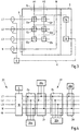
- Fig. 3 shows a switching matrix 2 and a measuring device 4, which are connected via a communication link 6.
- the measuring device 4 can also be part of the switching matrix 2.
- the measuring device 4 can also be arranged at a transfer point, for example in the form of a smart meter.
- inputs 8 are connected to outputs 10.
- the number of outputs 10 may be smaller than the number of inputs 8, in the present case there are two outputs A1 and A1 and three inputs L1, L2 and L3. But it is also possible that a third output 10 is present.
- a neutral conductor N can be looped through the switching matrix 2. The same applies to the protective conductor. In the case of a generator, the terminology can be reversed, then the outputs A1 and A2 are to be designated as inputs and the inputs L1, L2 and L3 as outputs.
- switches 12a-f are provided in the switching matrix.
- a switch 12 connects in each case an input L1, L2, L3 with an output A1, A2.
- the switches are driven by a processor 14.
- the processor is programmed so that in each case only the number of switches 12 is closed, which corresponds to the number of outputs A1, A2.
- an output A1, A2 is in each case more precisely connected only to an input L1, L2 or L3.
- the switches 12 are in communication with the processor 14.
- the processor is in communication with a communication device 16. Via the communication device 16, the measuring device 4 is connected to the switching matrix 2.
- the connection can be a Power Line Communication connection. Other possibilities of the connection are e.g. wireless connections. Any wired or wireless communication means and protocols are possible.
- the processor 14 operates the switches 12 such that a shift of the phase positions as in Fig. 2c shown is possible.
- the switches 12 switch such that a method as in Fig. 2c is shown is possible.
- the processor 14 receives information about a measurement from the measuring device 4 via the communication device 16. The processor 14 evaluates this information and controls the switches 12 so that asymmetries of an electrical variable on the phases L1, L2, L3 is counteracted.
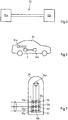
- Fig. 4 shows by way of example a transfer point 18 on a local network 20, which can be understood as a low-voltage network or distribution network.
- an access network 22 is connected to the transfer point 18, which is, for example, a house distribution.
- the transfer point 18 can be arranged at the house connection point as well as in the house distribution box.
- a measuring device 4 is arranged.
- the power of each phase L1, L2, L3 can be determined.
- the phase position, current, the voltage and / or active and reactive power can be determined. Concretely, it is sufficient if at least one of these electrical variables, preferably the current intensity, is determined on the measuring device 4.
- a switching matrix 2a-d is provided on the subscriber network 22 for each of the subscribers 30a-d.
- the subscriber 30a can be, for example, a photovoltaic system operated at least in two phases.
- the subscriber 30c can be, for example, a battery storage operated at least in two phases, and the subscriber 30b can be, for example, an electric vehicle which is connected in three phases but can only charge in two phases.
- a connection to the earthing conductor and the protective conductor for each of the participants 30 is understood and is therefore not shown.
- a single-phase powered consumer 30d shown.
- the subscriber 30d is operated with 10 A, for example. First, it is assumed in the following example that the photovoltaic system 30a and the battery storage 30c are not in operation. By the operation of the subscriber 30d, a phase is charged with 10A.
- the switching matrix 2d switches the phase L1 to the output and thus connects the subscriber 30d with the phase L1, which is then loaded with 10A.
- the electric vehicle 30b which is operated in a two-phase manner, normally has to comply with the specifications regarding maximum load capacity and phase unbalance. It should be noted that for the sake of simplicity, only the electric vehicle is considered, which is usually not the single device that must comply with the requirement for symmetry, but compliance with the requirement applies to the sum of the equipment operated by a customer.
- the measuring device 4 again measures the size and determines that the phase L1 is loaded with 10 A, or that, as the case may be, the phases L3 and L2 are therefore less loaded than the phase L1.
- the switching matrix 2b is instructed to phase L3 and L2 to connect with the electric vehicle. In total, this meant that the three phases L1, L2, L3 were loaded as evenly as possible.
- the photovoltaic system 30a and the battery storage 30c are now also considered.
- the photovoltaic system 30a can feed in two phases.
- the measuring device 4 represents e.g. determine that the electrical load at phases L1 and L2 is highest, e.g. in which it is determined that the voltage at the phases L1 and L2 is lower than at the phase L3.
- the switching matrix 2a is therefore controlled or controls itself such that the switch connects a subscriber-side input to the phase L1 and connects the second subscriber-side input to the phase L2. This increases the voltages at these phases L1 and L2 and reduces the imbalance.
- the battery storage 30c can load on two phases.
- the two outputs of the battery store, which are applied to the inputs of the switching matrix 2c can be connected to two outputs of the switching matrix 2c, which are applied to the phases L1, L2 and L3. This is done in such a way that the two inputs of the switching matrix 2c are coupled to those two outputs of the switching matrix 2c such that the power of the battery memory is fed into two of the phases L1, L2, L3 in which the voltage is lowest.
- Fig. 5 shows a charging cable 32 with two charging cable connectors 32a, 32b.
- a switching matrix 2 and / or a measuring device 4 may be integrated in the charging cable itself or in one of the charging cable plugs 32a, 32b.
- Fig. 6 shows an electric vehicle 34.
- a charge control circuit 34b can be fed via a charging socket 34a.
- the charge control circuit 34b can be operated, for example, two-phase.
- the charging socket 34a may be connected in three phases to a charging station.
- a switching matrix 2 may be connected in the vehicle 34 between the charging socket 34a and the charging control unit 34b. Depending on a measurement carried out, for example, in the switching matrix 2, two of the three input-side phases can be connected to the two outputs of the switching matrix 2.
- the charging station 36 may be connected on the input side with a switching matrix 2 to a distribution network 20.
- measuring devices 4 may be provided at the switching matrix 2 measuring devices 4 may be provided.
- the measuring devices can, for example, measure the voltage on the phases of the distribution network 20.
- the two phases with the highest voltages can be switched from the switching matrix 2 to the charging socket 36a.
- a third phase of the charging socket 36a may be switched blind, ie not connected to the distribution network 20. In this case, charging is only possible via two phases, whereby in each case the two phases are selected which are currently the least loaded in the network.
Description
Der Gegenstand betrifft ein Verfahren, eine Vorrichtung und eine Schaltmatrix zum Betreiben von elektrischen Verbrauchern oder Erzeugern an einem Teilnehmernetz.The subject matter relates to a method, a device and a switching matrix for operating electrical consumers or generators on a subscriber network.
Der Betrieb eines Mehrphasennetzes, insbesondere eines Dreiphasennetzes, beispielsweise eines Drehstromnetzes, ist weitgehend geregelt. Hierbei ist insbesondere die Leistungsaufnahme eines Teilnehmernetzes pro Phase beschränkt, um zu verhindern, dass eine Differenz einer elektrischen Größe zwischen den Phasen einen Höchstwert überschreitet. Durch Unsymmetrien an dem Teilnehmer entstehen erhöhte Verluste in dem Teilnehmernetz, welche zu vermeiden sind. Insbesondere führt eine ungleiche Belastung des Teilnehmernetzes an den Phasen zu einer Nullpunktverschiebung/Sternpunktverschiebung. Um diese auszugleichen sind Ausgleichsströme im Nullleiter notwendig, die unnötige Verluste verursachen.The operation of a multi-phase network, in particular a three-phase network, for example, a three-phase network, is largely regulated. Here, in particular, the power consumption of a subscriber network per phase is limited in order to prevent a difference in an electrical quantity between the phases from exceeding a maximum value. Unbalances at the subscriber result in increased losses in the subscriber network which are to be avoided. In particular, an unequal load of the subscriber network at the phases leads to a zero offset / neutral point shift. To compensate for these equalizing currents in the neutral are necessary, causing unnecessary losses.
Darüber hinaus hat eine aufgrund ungleicher Belastung unsymmetrische Spannung im Drehstromnetz negative Auswirkungen auf Verbraucher, die auf eine möglichst symmetrische Spannung angewiesen sind (z.B. Drehstrom-Asynchronmotoren für kontinuierliches Drehmoment. Bei nicht kontinuierlichem Drehmoment besteht die Gefahr von Lagerschäden aufgrund eines "nicht rund laufen" des Motors).In addition, unbalanced load in a three-phase system due to unequal load has a negative impact on loads that are as symmetrical as possible (eg three-phase asynchronous motors for continuous torque.) If torque is not continuous, there is a risk of bearing damage due to "not running smoothly" motor).
In der Regel ist die Lastverteilung im Dreiphasennetz aufgrund einer statistischen Verteilung im Wesentlichen gleich. So ist beispielsweise in einem Haushalt das Teilnehmernetz durch den Elektriker an den drei Phasen L1, L2 und L3 des Verteilnetzes angeschlossen. Hierbei erfolgt ein Anschluss der Teilnehmer des Haushaltes an eine der drei Phasen L1, L2, L3 im Wesentlichen nach dem Zufallsprinzip, nämlich je nachdem, an welche Phase der Elektriker die jeweilige Zuleitung im Verteilkasten angeschlossen hat. Aufgrund dieser statistischen Verteilung einer Vielzahl von leistungsschwachen Teilnehmern ist davon auszugehen, dass die Unsymmetrie im Teilnehmernetz und mithin im Verteilnetz, hier der Niederspannungsebene, unbeachtlich ist und es eine mehr oder weniger gleichmäßige Phasenauslastung gibt.As a rule, the load distribution in the three-phase network is essentially the same due to a statistical distribution. For example, in a household the subscriber network is connected by the electrician to the three phases L1, L2 and L3 of the distribution network. Here, a connection of the participants of the household to one of the three phases L1, L2, L3 takes place essentially at random, namely, depending on which phase the electrician has connected the respective supply line in the distribution box. Because of this statistical Distribution of a large number of low-performance participants is assumed that the imbalance in the subscriber network and thus in the distribution network, here the low voltage level, irrelevant and there is a more or less uniform phase utilization.
Um jedoch signifikante Unsymmetrien, insbesondere durch den Betrieb einzelner leistungsstarker Teilnehmer zu verhindern, wird in den technischen Anschlussbedingungen (TAB Niederspannung) gefordert, dass leistungsstarke Verbraucher mit einer Grenzleistung, in Deutschland beispielsweise über 4,6 kVA, an allen drei Phasen des Teilnehmernetzes zu betreiben sind. Die Verbraucher müssen so ausgelegt sein, dass sie eine jeweils gleichmäßige Phasenbelastung hervorrufen. Außerdem ist in den technischen Anschlussbedingungen gefordert, dass die maximale Unsymmetrie pro Netzanschluss einen Maximalwert, in Deutschland beispielsweise 4,6 kVA, nicht überschreiten darf. Dies führt zu Einschränkungen der Teilnehmer, insbesondere dazu, dass Teilnehmer die nur einphasig betrieben werden, Leistungen von beispielsweise 4,6 kVA, insbesondere Leistungen, die der maximal zulässigen Unsymmetrie genügen, nicht überschreiten dürfen.However, in order to prevent significant asymmetries, in particular due to the operation of individual high-performance subscribers, it is required in the technical connection conditions (TAB low-voltage) to operate high-performance consumers with a limit power, in Germany for example over 4.6 kVA, on all three phases of the subscriber network are. Consumers must be designed to produce uniform phase loading. In addition, it is required in the technical connection conditions that the maximum imbalance per grid connection must not exceed a maximum value, in Germany, for example, 4.6 kVA. This leads to restrictions of the participants, in particular to the fact that subscribers who are only operated in a single phase, services of, for example, 4.6 kVA, in particular services that meet the maximum allowable asymmetry must not exceed.
So ist es beispielsweise in Deutschland gefordert, dass einphasig angeschlossene Photovoltaikeinrichtungen nur maximal 4,6 kVA in diese Phase in das Verteilnetz einspeisen dürfen. Auch einphasig ladende Elektrofahrzeuge dürfen aus dieser einzelnen Phase nicht mehr als 4,6 kVA beziehen. Die technischen Anschlussbedingungen führen somit zur Leistungsbeschränkung angeschlossener Teilnehmer aufgrund der geforderten Symmetrie an den Phasen des Verteilnetzes, welche im Zweifel zu einer Leistungseinschränkung der Teilnehmer führen kann. Die tatsächlich über das Teilnehmernetz übertragbare Leistung ist wesentlich höher als die angegebene Grenzleistung, darf jedoch aus Gründen der geforderten Symmetrie am Übergabepunkt die Grenzleistung nicht überschreiten.For example, in Germany it is required that single-phase connected photovoltaic devices may only feed a maximum of 4.6 kVA into this phase into the distribution network. Single-phase charging electric vehicles may not receive more than 4.6 kVA from this single phase. The technical connection conditions thus lead to power limitation of connected participants due to the required symmetry of the phases of the distribution network, which can lead to a power limitation of the participants in case of doubt. The power actually transmitted via the subscriber network is significantly higher than the specified limit power, but may not exceed the limit power for reasons of required symmetry at the transfer point.
Der Anschluss von Elektrofahrzeugen wird zunehmend als problematisch erkannt. So belasten Elektrofahrzeuge das Netz weder zeitlich noch räumlich deterministisch vorhersagbar. Auch wollen Autohersteller zum Teil auch zweiphasig laden, so dass die zulässige Schieflast zukünftig auch nur auf der vom Fahrzeug nicht belasteten Phase liegen kann. Es kann zu erheblichen Schieflasten kommen, wenn nicht in den Betrieb solcher Verbraucher eingegriffen wird. Auf der anderen Seite kann ein Erzeuger, z.B. eine KWK-Heizung, eine Solaranlage oder dergleichen teilweise auch nur ein- oder zweiphasig betrieben werden. Diese Einspeisungen führen in der Regel ebenfalls zu Schieflasten. Speist z.B. eine Solaranlage auf der Phase L1 ein und bezieht ein Elektrofahrzeug auf den Phasen L2 und L3 elektrische Leistung, so ist die Schieflast denkbar groß.The connection of electric vehicles is increasingly recognized as problematic. Thus, electric vehicles burden the network neither temporally nor spatially deterministic predictable. In addition, car manufacturers also want to charge two-phase charging, so that the permissible unbalanced load can only be on the phase not loaded by the vehicle in the future. It can lead to significant unbalanced loads, if not intervened in the operation of such consumers. On the other hand, a generator, for example, a cogeneration heating, a solar system or the like can sometimes be operated only one or two phases. These feeds usually also lead to unbalanced loads. For example, if a solar system feeds in phase L1 and an electric vehicle receives electrical power on phases L2 and L3, the unbalanced load is very high.
Das Dokument
Dem Gegenstand lag somit die Aufgabe zugrunde, die Phasenlage eines Teilnehmers, z.B. einer Last oder eines Einspeisers, z.B. einer Photovoltaikanlage an aktuelle Bedingungen anpassen zu können.
Diese Aufgabe wird gegenständlich durch ein Verfahren nach Anspruch 1, ein Verfahren nach Anspruch 6, eine Vorrichtung nach Anspruch 7, eine Vorrichtung nach Anspruch 12 sowie eine Schaltmatrix nach Anspruch 13 oder 14 gelöst.
Nachfolgend ist die Rede von Teilnehmern, wenn alternativ sowohl Verbraucher als auch Erzeuger (auch Einspeiser genannt) gemeint sein können. Der Gegenstand sowie alle beschriebenen Ausführungsbeispiele lassen sich sowohl auf einen elektrischen Verbraucher als auch einen elektrischen Erzeuger anwenden.
Bei einem Verbraucher erfolgt eine Zuordnung zwischen einem Eingang der Schaltmatrix und einem Ausgang der Schaltmatrix, wobei der Eingang an einem Teilnehmernetz angeschlossen sein kann und der Ausgang an dem Verbraucher. Die Schaltmatrix hat in diesem Fall mehr Eingänge als Ausgänge. Bei einem Erzeuger erfolgt auch eine Zuordnung zwischen einem Eingang der Schaltmatrix und einem Ausgang der Schaltmatrix, wobei aber der Eingang an dem Erzeuger und der Ausgang an dem Teilnehmernetz angeschlossen sein kann. In diesem Fall hat die Schaltmatrix mehr Ausgänge als Eingänge.The object was therefore the object of being able to adjust the phase of a participant, such as a load or a feeder, such as a photovoltaic system to current conditions.
This object is solved objectively by a method according to claim 1, a method according to
The following is the talk of participants, if alternatively both consumers and producers (also called feeders) may be meant. The article as well as all described embodiments can be applied to both an electrical consumer and an electric generator.
In the case of a consumer, an association takes place between an input of the switching matrix and an output of the switching matrix, wherein the input can be connected to a subscriber network and the output to the consumer. The switch matrix has more inputs than outputs in this case. In the case of a generator, an association also takes place between an input of the switching matrix and an output of the switching matrix, but the input at the generator and the output at the subscriber network can be connected. In this case, the switch matrix has more outputs than inputs.
In beiden Fällen ist die Schaltmatrix mit mehr Anschlüssen (Eingänge bzw. Ausgänge) an dem Teilnehmernetz angeschlossen als an dem Teilnehmer. Vorzugsweise erfolgt das Zuordnen von zumindest teilnehmerseitigen Anschlüssen der Schaltmatrix zu zumindest teilnehmernetzseitigen Anschlüssen der Schaltmatrix abhängig von der Messung. Vorzugsweise ist die Anzahl der teilnehmerseitigen Anschlüsse geringer als die Anzahl der teilnehmernetzseitigen Anschlüsse. Insbesondere kann eine Zuweisung zwischen den teilnehmerseitigen Anschlüsse und den teilnehmernetzseitigen Anschlüssen so erfolgen, dass weniger teilnehmernetzseitige Anschlüsse teilnehmerseitigen Anschlüssen zugeordnet werden, als teilnehmernetzseitige Anschlüsse vorhanden sind. Im Falle einer Last können teilnehmerseitige Anschlüsse Ausgänge und teilnehmernetzseitige Anschlüsse Eingänge sein. Im Falle eines Einspeisers können teilnehmerseitige Anschlüsse Eingänge und teilnehmernetzseitige Anschlüsse Ausgänge sein. Somit kann gegenständlich stets eine Selektion erfolgen, welche Phase oder welche Phasen des Teilnehmernetzes mit dem Teilnehmer verbunden werden. Hierdurch kann auf Schieflasten im Teilnehmernetz reagiert werden.In both cases, the switching matrix is connected to the subscriber network with more connections (inputs or outputs) than at the subscriber. Preferably, the assignment of at least subscriber-side connections of the switching matrix to at least subscriber network-side connections of the switching matrix takes place as a function of the measurement. Preferably, the number of subscriber-side connections is less than the number of subscriber network-side connections. In particular, an assignment between the subscriber-side connections and the subscriber network-side connections can take place such that fewer subscriber network-side connections are assigned to subscriber-side connections, as subscriber network-side connections are present. In the case of a load, subscriber-side terminals may be outputs and subscriber-network-side terminals inputs. In the case of a feeder, subscriber-side terminals may be inputs and subscriber-network-side terminals may be outputs. Consequently, a selection can always be made objectively, which phase or phases of the subscriber network are connected to the subscriber. This can be reacted to unbalances in the subscriber network.
Bei dem gegenständlichen Verfahren kann der Verbraucher an zumindest einer Phase betreibbar sein. Ein Verbraucher kann z.B. ein Elektrofahrzeug oder ein sonstiger Hochleistungsverbraucher sein. Insbesondere kann der Verbraucher mit einer Last von mehr als 4,6 kVA pro Phase betreibbar sein.In the subject method, the consumer may be operable on at least one phase. A consumer may e.g. an electric vehicle or other high-performance consumer. In particular, the consumer may be operable with a load of more than 4.6 kVA per phase.
Mit Hilfe einer Messeinrichtung kann zumindest eine elektrische Größe an zumindest zwei eingangsseitigen, vorzugsweise teilnehmernetzseitigen Phasen einer zumindest zwei Ausgänge aufweisenden Schaltmatrix gemessen werden.With the aid of a measuring device, at least one electrical variable can be measured at at least two input-side, preferably subscriber-network-side phases of a switching matrix having at least two outputs.
Mit neuartigen Messstellen, insbesondere sogenannten Smart Meter, kann in einem Teilnehmernetz nicht nur die Gesamtsystemleistung erfasst werden, sondern die Leistungsbilanz einer jeden Phase. Es kann somit erfasst werden, welche Ströme pro Phase fließen und ermittelt werden, wie groß eine jeweilige Unsymmetrie zwischen den einzelnen Phasen ist. Mittels dieser Information ist es möglich, die Schaltmatrix so zu steuern, dass die Belastung der einzelnen Phasen symmetriert werden kann. Dies führt zu einer besseren Netzauslastung, da jede Phase möglichst optimiert genutzt wird und andererseits können Restriktionen hinsichtlich der maximalen Leistung pro Phase von Teilnehmer aufgehoben bzw. erhöht werden, da sich die Teilnehmer hinsichtlich der Phasenbelastung gegenseitig kompensieren können.With novel measuring points, in particular so-called smart meters, not only the overall system performance can be recorded in a subscriber network, but the power balance of each phase. It can thus be detected which currents flow per phase and how large a particular asymmetry between the individual phases. By means of this information, it is possible to control the switching matrix so that the load of the individual phases can be balanced. This leads to better network utilization, since each phase is optimally utilized and, on the other hand, restrictions with respect to the maximum power per phase of subscribers can be canceled or increased, since the subscribers can compensate each other with regard to the phase load.
Zur Ermittlung der Belastung der einzelnen Phasen kann eine elektrische Größe, vorzugweise die Stromstärke, an den jeweiligen Phasen teilnehmernetzseitig ermittelt werden. Dabei kann es notwendig sein, die elektrische Größe an zumindest zwei Phasen eines Teilnehmernetzes, insbesondere an einem Übergabepunkt zwischen einem Verteilnetz und dem Teilnehmernetz, zu erfassen. Insbesondere wird dabei die elektrische Größe in dem Teilnehmernetz, beispielsweise in dem Hausverteilnetz gemessen.To determine the load of the individual phases, an electrical variable, preferably the current intensity, can be determined on the subscriber network side at the respective phases. In this case, it may be necessary to detect the electrical variable at at least two phases of an subscriber network, in particular at a transfer point between a distribution network and the subscriber network. In particular, the electrical variable is measured in the subscriber network, for example in the home distribution network.
Die jeweils gemessene elektrische Größe, insbesondere die Stromstärke bzw. auch andere gemessene Größen, wie nachfolgend noch erläutert werden wird, können zwischen zumindest den beiden teilnehmernetzseitigen Phasen miteinander verglichen werden. Es kann ermittelt werden, welche der Größen insbesondere betragsmäßig die größte ist. Auch kann ein Vorzeichen berücksichtigt werden. Anschließend kann die Schaltmatrix so betrieben werden, dass der teilnehmerseitige Anschluss, insbesondere der Ausgang der Schaltmatrix, an den der Verbraucher angeschlossen ist, an denjenigen teilnehmernetzseitigen Anschluss, insbesondere den Eingang der Schaltmatrix angeschlossen wird, bei dem die elektrische Größe, z.B. die Stromstärke oder die Gesamtleistung am kleinsten oder am größten, z.B. bei einer Strommessung, ist.The respectively measured electrical variable, in particular the current intensity or also other measured variables, as will be explained below, can be compared with one another between at least the two subscriber network-side phases. It can be determined which of the variables is in particular the largest in terms of amount. Also a sign can be considered. Subsequently, the switching matrix can be operated so that the subscriber-side terminal, in particular the output of the switching matrix to which the consumer is connected, is connected to the subscriber network-side terminal, in particular the input of the switching matrix, in which the electrical variable, e.g. the current or total power is the smallest or the largest, e.g. at a current measurement is.
Gemäß einem Ausführungsbespiel ist die elektrische Größe eine elektrische Stromstärke und/oder ein elektrisches Potential, insbesondere eine Spannung zwischen einer jeweiligen Phase und einem Nullleiter bzw. der Spannung zwischen den Phasen untereinander und/oder die elektrische Leistung an einer jeweiligen Phase und/oder eine Phasendifferenz zwischen Strom und Spannung an einer jeweiligen Phase. Vorzugsweise erfolgt eine Symmetrierung hinsichtlich möglichst aller genannten elektrischen Größen oder einer Auswahl von mehreren der genannten elektrischen Größen durch Schalten der Schaltmatrix abhängig von den gemessenen Größen.According to one exemplary embodiment, the electrical variable is an electrical current strength and / or an electrical potential, in particular a voltage between a respective phase and a neutral conductor or the voltage between the phases with one another and / or the electrical power at a respective one Phase and / or a phase difference between current and voltage at a respective phase. Symmetrization is preferably carried out with respect to as many electrical variables as possible or a selection of a plurality of said electrical variables by switching the switching matrix as a function of the measured variables.
Um eine Zuordnung jeweils einer Phase des Teilnehmernetzes zu einem der teilnehmerseitigen Anschlüsse, insbesondere Ausgänge der Schaltmatrix zu ermöglichen, können die teilnehmernetzseitigen Anschlüsse der Schaltmatrix mit verschiedenen Phasen eines Teilnehmernetzes verbunden sein. Hierdurch kann eine Auswahl getroffen werden, welcher Phase des Teilnehmernetzes mit dem Teilnehmer verbunden wird.In order to enable assignment of one phase each of the subscriber network to one of the subscriber-side connections, in particular outputs of the switch matrix, the subscriber network-side connections of the switch matrix can be connected to different phases of an subscriber network. In this way, a selection can be made, which phase of the subscriber network is connected to the subscriber.
Zumindest ein Eingang der Schaltmatrix kann zu zumindest einem Ausgang der Schaltmatrix zugeordnet werden. Hierzu kann eine Schaltung vorgesehen sein, die abhängig von der Messung jeweils einen Eingang auf einen Ausgang schaltet. Es werden bevorzugt weniger als alle Eingänge auf vorzugsweise alle Ausgänge geschaltet. Eine Auswahl der Eingänge, die genutzt wird, also auf Ausgänge geschaltet wird, ist dadurch möglich, dass bei der Zuordnung in der Schaltmatrix weniger Ausgänge Eingängen zugewiesen werden, als Eingänge vorhanden sind. Somit kann zumindest ein Eingang frei von einer Zuordnung zu einem Ausgang sein, wodurch dieser Eingang durch den Verbraucher nicht belastet wird.At least one input of the switching matrix can be assigned to at least one output of the switching matrix. For this purpose, a circuit may be provided which switches an input to an output depending on the measurement. Preferably less than all inputs are switched to preferably all outputs. A selection of the inputs that is used, that is, switched to outputs, is possible because, when assigned in the switching matrix, fewer outputs are assigned to inputs than there are inputs. Thus, at least one input can be free from an assignment to an output, whereby this input is not burdened by the consumer.
Die Schaltmatrix kann nach einem Ausführungsbeispiel genau einen Ausgang aufweisen. In diesem Fall kann der Verbraucher ein einphasiger Verbraucher sein. Im Falle eines einphasigen Einspeisers hätte die Schaltmatrix ggf. genau einen Eingang. Auch kann der Verbraucher an genau zwei Phasen betrieben werden. Die Schaltmatrix hätte dann genau zwei Ausgänge. Im Falle eines zweiphasigen Erzeugers hätte die Schaltmatrix zwei Eingänge. Die Schaltmatrix hat vorzugsweise eine gleiche Anzahl an Ausgängen wie die Anzahl der Phasen ist, mit denen der Verbraucher betrieben wird. Im Falle eines Erzeugers hätte die Schaltmatrix vorzugsweise eine gleiche Anzahl an Eingängen wie die Anzahl der Phasen ist, mit denen der Erzeuger betrieben wird. Auch kann die Anzahl der Eingänge, bzw. Ausgänge bei einem Erzeuger, gleich der Anzahl der Phasen des Teilnehmernetzes sein. Somit kann die Schaltmatrix vorzugsweise teilnehmernetzseitig mit allen Phasen verbunden werden und ermöglicht eine selektive Zuordnung von Phasen des Teilnehmernetzes zu einzelnen Phasen des Teilnehmers, abhängig von Informationen zu der gemessenen Größe.The switching matrix may have exactly one output according to one embodiment. In this case, the consumer may be a single-phase consumer. In the case of a single-phase feeder, the switching matrix would possibly have exactly one input. Also, the consumer can be operated on exactly two phases. The switching matrix would have exactly two outputs. In the case of a two-phase generator, the switching matrix would have two inputs. The switching matrix preferably has an equal number of outputs as the number of phases with which the consumer is operated. In the case of a generator, the switching matrix would preferably have an equal number Inputs, such as the number of phases that the producer is operating. Also, the number of inputs, or outputs in a generator, be equal to the number of phases of the subscriber network. Thus, the switching matrix can preferably be connected to all phases of the subscriber network and allows a selective assignment of phases of the subscriber network to individual phases of the subscriber, depending on information about the measured variable.
Mittels der Schaltmatrix kann ein Strompfad zwischen jeweils einem teilnehmernetzseitigen Anschluss und zumindest einem teilnehmerseitigen Anschluss geschaltet werden. Somit kann eine Symmetrierung der elektrischen Größen auf der Seite des Teilnehmernetzes erfolgen, in dem die Schaltmatrix die Zuordnung so vornimmt, dass die elektrischen Größen der Phasen des Teilnehmernetzes durch die vom Teilnehmer bezogene bzw. eingebrachte elektrische Größe einander angenähert werden.By means of the switching matrix, a current path can be connected between in each case one subscriber network-side connection and at least one subscriber-side connection. Thus, a symmetrization of the electrical quantities can be carried out on the side of the subscriber network, in which the switching matrix makes the assignment so that the electrical quantities of the phases of the subscriber network are approximated by the electrical size taken from the subscriber or introduced.
Es wird vorgeschlagen, dass zumindest eine elektrische Größe laufend gemessen wird. Hierzu kann vorzugsweise zyklisch eine Messung vorgenommen werden. Die Messung kann in zeitlichen Abständen erfolgen. Somit kann die Zuordnung zwischen Eingang und Ausgang dynamisch angepasst werden und auf sich verändernde Netzbedingungen reagiert werden. Die Zuordnung erfolgt abhängig von der laufenden Messung. Insbesondere kann dynamisch, also in zeitlichen Abständen zyklisch überwacht werden, ob die vorhandene Zuordnung die optimale Symmetrierung bewirkt. Auch kann bei einer Messung kurzzeitig, also z.B. für die Dauer der Messung, der Strompfad zwischen Eingang und Ausgang getrennt werden, um die Messung unabhängig von dem Teilnehmer zu machen. Auch kann eine Messung am teilnehmerseitigen Anschluss erfolgen. Somit kann der Wert der elektrischen Größe des Teilnehmers bestimmt werden.It is proposed that at least one electrical variable is measured continuously. For this purpose, a measurement can preferably be made cyclically. The measurement can be done at intervals. Thus, the assignment between input and output can be dynamically adjusted and responded to changing network conditions. The assignment is dependent on the current measurement. In particular, it is possible to monitor cyclically, that is to say cyclically at intervals, as to whether the existing assignment brings about the optimum symmetrization. Also, during a measurement, for a short time, e.g. for the duration of the measurement, the current path between input and output are separated to make the measurement independent of the participant. Also, a measurement can be made on the subscriber side connection. Thus, the value of the electrical size of the subscriber can be determined.
Es wird vorgeschlagen, dass die Zuordnung abhängig von der Messung während des laufenden Betriebs des Verbrauchers verändert wird. Verändern sich die Bedingungen im Teilnehmernetz kann es sinnvoll sein, die Belastung bzw. Entlastung der Phasen des Teilnehmernetzes durch den Teilnehmer zu verändern. Zunächst kann jedoch auch die Zuordnung zu Beginn des Betriebs des Verbrauchers abhängig von der Messung erfolgen. Auch kann diese Zuordnung zu Beginn eines Betriebs des Verbrauchers erfolgen und für die Dauer des Betriebs des Teilnehmers unverändert bleiben. Bei einer solchen statischen Zuordnung ist die Anzahl der Messungen geringer und die Anzahl der Schaltvorgänge der Schaltmatrix, was zur Verlängerung der Lebensdauer der Schaltmatrix beiträgt.It is proposed that the assignment be changed depending on the measurement during the operation of the consumer. If the conditions in the subscriber network change, it may make sense to load or relieve the phases of the subscriber network by the subscriber. First, however, the assignment can be made at the beginning of the operation of the consumer depending on the measurement. Also, this assignment can be made at the beginning of an operation of the consumer and remain unchanged for the duration of the operation of the subscriber. With such a static allocation, the number of measurements is smaller and the number of switching operations of the switching matrix, which contributes to the extension of the life of the switching matrix.
Es wird vorgeschlagen, dass die Eingänge nacheinander mit zunehmendem Betrag der gemessenen elektrischen Größe jeweils einem der Ausgänge zugeordnet werden. Wird die elektrische Größe Stromstärke oder Last der Phase gemessen, ist es sinnvoll, zunächst die Phase des Teilnehmernetzes mit der Verbraucher zu verbinden, an der diese Größe am geringsten ist und nach und nach die Phasen mit dem Verbraucher zu verbinden, bei denen diese Größe danach jeweils am geringsten ist. Bei der elektrischen Größe Spannung in den Phasen des Teilnehmernetzes wäre zunächst die Phase mit dem größten Betrag mit dem Verbraucher zu verbinden. Bei einem Erzeuger wäre die Reihenfolge bei allen elektrischen Größen genau umgekehrt. Wird insbesondere die elektrische Größe Stromstärke oder Last der Phase gemessen, ist es sinnvoll, zunächst die Phase des Teilnehmernetzes mit der Erzeuger zu verbinden, an der diese Größe am größten ist und nach und nach die Phasen mit dem Verbraucher zu verbinden, bei denen diese Größe danach jeweils größer ist. Bei der elektrischen Größe Spannung in den Phasen des Teilnehmernetzes wäre insbesondere zunächst die Phase mit dem kleinsten Betrag mit dem Erzeuger zu verbinden.It is proposed that the inputs are each assigned in succession to one of the outputs as the magnitude of the measured electrical quantity increases. When measuring the magnitude of electrical current or load of the phase, it makes sense to first connect the phase of the subscriber network to the consumer at which this size is lowest and to gradually connect the phases to the consumer at that size thereafter each is the lowest. In the electrical size voltage in the phases of the subscriber network would first be the phase with the largest amount to connect to the consumer. For a producer, the order would be the exact opposite for all electrical quantities. In particular, if the electrical magnitude of the current or load of the phase is measured, it makes sense to first connect the phase of the subscriber network to the generator at which this size is greatest and to gradually connect the phases to the consumer in which this size thereafter each is larger. In the case of the electrical variable voltage in the phases of the subscriber network, in particular, first the phase with the smallest amount would have to be connected to the generator.
Bei dem gegenständlichen Verfahren zum Betreiben eines elektrischen Erzeugers an zumindest einer Phase eines Teilnehmernetzes wird vorgeschlagen, dass zumindest eine elektrische Größe des Teilnehmernetzes gemessen wird, wobei das Teilnehmernetz mit zumindest zwei verschiedenen Phasen an einer zumindest zwei Ausgänge aufweisenden Schaltmatrix angeschlossen ist. Anschließend kann ein Zuordnen von zumindest einem Eingang der Schaltmatrix zu zumindest einem Ausgang der Schaltmatrix abhängig von der Messung erfolgen. Im Falle eines Erzeugers kann eine Auswahl der Ausgänge, die genutzt wird, also auf Eingänge geschaltet wird, dadurch ermöglicht sein, dass bei der Zuordnung in der Schaltmatrix weniger Eingänge Ausgängen zugewiesen werden, als Ausgänge vorhanden sind. Somit kann zumindest ein Ausgang frei von einer Zuordnung zu einem Eingang sein, wodurch dieser Ausgang durch den Erzeuger nicht gespeist wird. Somit können die erzeugerseitigen Eingänge selektiv auf ausgewählte Ausgänge geschaltet werden und Unsymmetrien zwischen Phasen des Teilnehmernetzes verringert werden.In the subject method for operating an electrical generator on at least one phase of a subscriber network, it is proposed that at least one electrical variable of the subscriber network be measured, the subscriber network having at least two different phases being connected to a switching matrix having at least two outputs. Subsequently, at least one input of the switching matrix can be assigned to at least one output of the switching matrix as a function of the measurement. in case of a Generator, a selection of the outputs that is used, that is switched to inputs, thereby be made possible that when assigning in the switching matrix fewer inputs outputs are assigned, as outputs are available. Thus, at least one output may be free from an assignment to an input, whereby this output is not fed by the generator. Thus, the generator side inputs can be selectively switched to selected outputs and unbalances between phases of the subscriber network reduced.
Ein weiterer Gegenstand ist eine Vorrichtung bzw. ein System eingerichtet zum Betreiben eines elektrischen Verbrauchers an zumindest einer Phase umfassend eine Messeinrichtung eingerichtet zum Messen von zumindest einer elektrischen Größe an zumindest zwei teilnehmernetzseitigen Phasen einer zumindest zwei teilnehmernetzseitigen Anschlüsse aufweisenden Schaltmatrix, mit einer Schaltmatrix eingerichtet zum Zuordnen von zumindest einem teilnehmerseitigen Anschluss der Schaltmatrix zu zumindest einem teilnehmernetzseitigen Anschluss der Schaltmatrix abhängig von der Messung, wobei die Schaltmatrix zumindest einen teilnehmerseitigen Anschluss weniger als teilnehmernetzseitige Anschlüsse aufweist. Die Anschlüsse können im Fall eines Verbrauchers teilnehmerseitig Ausgänge und teilnehmernetzseitig Eingänge sein. Die Anschlüsse können im Fall eines Einspeisers teilnehmerseitig Eingänge und teilnehmernetzseitig Ausgänge sein.A further subject matter is a device or a system configured for operating an electrical load on at least one phase comprising a measuring device configured to measure at least one electrical variable at at least two subscriber network side phases of a switching matrix having at least two subscriber network-side connections, with a switching matrix configured for assignment from at least one subscriber-side connection of the switching matrix to at least one subscriber network-side connection of the switching matrix as a function of the measurement, wherein the switching matrix has at least one subscriber-side connection less than subscriber network-side connections. In the case of a consumer, the connections can be outputs on the subscriber side and inputs on the subscriber network side. In the case of a feeder, the connections can be inputs on the subscriber side and outputs on the subscriber line side.
Die Messeinrichtung und/oder die Schaltmatrix können in dem Teilnehmer integriert sein. In diesem Fall kann der Teilnehmer selbstständig eine Verbindung zu ausgewählten Phasen eines Teilnehmernetzes herstellen.The measuring device and / or the switching matrix can be integrated in the subscriber. In this case, the subscriber can independently establish a connection to selected phases of a subscriber network.
Auch können die Messeinrichtung und/oder die Schaltmatrix räumlich von dem Teilnehmer getrennt, insbesondere in einem eigenen Gehäuse gebildet sind. Die Messeinrichtung kann z.B. an einem Übergabepunkt zwischen dem Teilnehmernetz und einem Verteilnetz, insbesondere im Bereich eines Hausanschlusses angeordnet sein. Die Messeinrichtung kann die Information zu der Messung, also z.B. ein Schaltbefehl oder die Größe eines gemessenen Wertes an die Schaltmatrix übermitteln. Die Schaltmatrix kann z.B. zwischen dem Übergabepunkt und dem Teilnehmer, insbesondere als eigenständige Baugruppe gebildet sein. Somit können Teilnehmer zur Durchführung des Gegenstandes nachgerüstet werden, in dem in einem Verbindungskabel zwischen Teilnehmernetz und Teilnehmer eine Schaltmatrix angeordnet wird.The measuring device and / or the switching matrix can also be spatially separated from the subscriber, in particular in a separate housing. The measuring device can be arranged, for example, at a transfer point between the subscriber network and a distribution network, in particular in the area of a house connection. The measuring device can be the information for the measurement, so for example, a switching command or the size of a measured value to the switching matrix to transfer. The switching matrix can be formed, for example, between the transfer point and the subscriber, in particular as an independent module. Thus, subscribers can be retrofitted to carry out the article, in which a switch matrix is arranged in a connection cable between subscriber network and subscriber.
In der Schaltmatrix können elektrische Schalter vorzugsweise als Halbleiterbauelemente, insbesondere als Leistungshalbleiter gebildet sein und mit einem geeigneten Prozessor abhängig von der Information zu der Messung geschaltet werden. Ein Prozessor kann in der Schaltmatrix oder der Messeinrichtung dazu programmiert sein, abhängig von einer Information zur Messung und einer Information zur elektrischen Leistung bzw. Belastung, Entlastung des Teilnehmernetzes durch den Teilnehmer die Zuordnung so vorzunehmen, dass eine momentane Unsymmetrie im Teilnehmernetz durch die elektrischen Eigenschaften des Teilnehmers verringert wird.In the switching matrix, electrical switches can preferably be formed as semiconductor components, in particular as power semiconductors, and switched with a suitable processor depending on the information for the measurement. A processor can be programmed in the switching matrix or the measuring device to make the assignment in such a way that an instantaneous asymmetry in the subscriber network is determined by the electrical properties, depending on information for measuring and information about the electrical power or load, relieving the subscriber network by the subscriber of the subscriber is reduced.
Die Messeinrichtung und/oder die Schaltmatrix können bevorzugt in einer Ladevorrichtung, einem Ladekabel oder einem Ladestecker für Elektrofahrzeuge integriert sein. Auch kann die Messeinrichtung und/oder die Schaltmatrix in einem Elektrofahrzeug integriert sein. Hierdurch kann ein Elektrofahrzeug unmittelbar vom Hersteller zur Durchführung des Verfahrens eingerichtet sein, oder durch geeignete Ladevorrichtungen, Ladekabel oder Ladestecker nachgerüstet werden.The measuring device and / or the switching matrix may preferably be integrated in a charging device, a charging cable or a charging plug for electric vehicles. Also, the measuring device and / or the switching matrix can be integrated in an electric vehicle. As a result, an electric vehicle can be set up directly by the manufacturer to carry out the method, or can be retrofitted by means of suitable charging devices, charging cables or charging plugs.
Um die Information zu Messungen von der Messeinrichtung zur Schaltmatrix übermitteln zu können, wird vorgeschlagen, dass die Messeinrichtung und die Schaltmatrix in Wirkverbindung miteinander geschaltet sind, insbesondere dass zwischen der Messeinrichtung und der Schaltmatrix eine Kommunikationsverbindung gebildet ist. Der Schaltbefehl kann in der Messeinrichtung erstellt werden und als Information zur Messung an die Schaltmatrix übermittelt werden. Auch kann die Information zur Messung derart sein, dass diese die Reihenfolge der Werte (Beträge und/oder Vorzeichen) der elektrischen Größen an den Phasen des Teilnehmernetzes beinhaltet und in der Schaltmatrix der Prozessor diese Information auswertet und in Schaltbefehle umwandelt. Schließlich kann auch der Wert der Messung selbst übertragen werden und in der Schaltmatrix geeignet verarbeitet werden.In order to be able to transmit the information for measurements from the measuring device to the switching matrix, it is proposed that the measuring device and the switching matrix are connected in operative connection with one another, in particular that a communication connection is formed between the measuring device and the switching matrix. The switching command can be created in the measuring device and transmitted as information for measurement to the switching matrix. Also, the information for measurement may be such that it indicates the order of the values (magnitudes and / or signs) of the electrical quantities at the phases of the subscriber network includes and in the switching matrix, the processor evaluates this information and converts it into switching commands. Finally, the value of the measurement itself can also be transmitted and suitably processed in the switching matrix.
Es wird vorgeschlagen, dass die Messeinrichtung als Teil eines Stromzählers, insbesondere als Teil eines Smart Meters gebildet ist. Dies kann insbesondere dann vorteilhaft sein, wenn die Messeinrichtung an einem Übergabepunkt angeordnet ist.It is proposed that the measuring device is formed as part of an electricity meter, in particular as part of a smart meter. This can be advantageous in particular if the measuring device is arranged at a transfer point.
Gegenständlich kann ein Teilnehmernetz z.B. ein Hausverteilnetz sein. Das entsprechende Verteilnetz kann dann das Niederspannungsnetz des Energieversorgers bzw. Verteilnetzbetreibers sein. Der Übergabepunkt kann der Hausanschlusspunkt sein. In diesem Fall ist es möglich, Unsymmetrien innerhalb des Hausnetzes festzustellen und durch einen entsprechenden Betrieb der Schaltmatrix diese Unsymmetrien zumindest teilweise zu kompensieren. Insbesondere kann eine Verschiebung des Nullpunktes bzw. Sternpunktes bewirkt werden, derart, dass dieser sich dem Sternpunkt bei symmetrischer Last annähert. Insbesondere sollen Nullleiterströme verkleinert, vorzugsweise minimiert werden.Concretely, a subscriber network may e.g. be a home distribution network. The corresponding distribution network can then be the low-voltage network of the energy supplier or distribution network operator. The transfer point can be the house connection point. In this case, it is possible to detect asymmetries within the home network and to compensate for these asymmetries at least partially by a corresponding operation of the switching matrix. In particular, a shift of the zero point or star point can be effected such that it approaches the star point with symmetrical load. In particular, neutral conductor currents are to be reduced, preferably minimized.
Gemäß einem Ausführungsbeispiel wird vorgeschlagen, dass das Teilnehmernetz zumindest drei Phasen aufweist. Ein solches Teilnehmernetz, insbesondere ein Drehstromnetz, ist häufig als Hausverteilnetz oder auch als Ortsverteilnetz vorhanden. Die Phasendifferenz der drei Phasen beträgt in der Regel 120°. Ein mehr als Dreiphasennetz ist jedoch auch möglich. Sobald die elektrischen Größe der Phasen ermittelt wurde, kann die Reihenfolge der Werte der gemessenen elektrischen Größe ermittelt werden. Anschließend kann eine Schaltmatrix angewiesen werden, die Eingänge und Ausgänge so zu verschalten, dass sich die Werte der gemessenen Größen einander annähern.According to one embodiment, it is proposed that the subscriber network has at least three phases. Such a subscriber network, in particular a three-phase network, is often present as a home distribution network or as a local distribution network. The phase difference of the three phases is usually 120 °. A more than three-phase network is also possible. Once the electrical size of the phases has been determined, the order of the values of the measured electrical quantity can be determined. Subsequently, a switching matrix can be instructed to interconnect the inputs and outputs in such a way that the values of the measured quantities approximate each other.
In vorteilhafter Weise werden die elektrischen Größen der Phasen an dem Übergabepunkt einander angenähert. Dies bedeutet, dass die Werte der elektrischen Größen pro Phase durch den Betrieb der Schaltmatrix verändert, insbesondere angehoben oder abgesenkt werden können, insbesondere so, dass sie sich einander zumindest betragsmäßig annähern. Ziel des Betreibens der Schaltmatrix ist es dabei, eine möglichst symmetrische Verteilung der elektrischen Leistung über alle Phasen zu erzielen.Advantageously, the electrical quantities of the phases are approximated at the transfer point. This means that the values of the electrical quantities per phase are changed by the operation of the switching matrix, in particular can be raised or lowered, in particular so that they approach each other at least in terms of amount. The aim of operating the switching matrix is to achieve the most symmetrical distribution of electrical power over all phases.
Bei der dynamischen Messung der elektrischen Größen wird vorgeschlagen, dass im laufenden Betrieb, beispielsweise in Intervallen, beispielsweise in Sekunden-, 30 Sekunden-, 1 Minuten- oder 10 Minuten-Schritten die elektrischen Größen gemessen werden. Anschließend kann dynamisch der laufende Betrieb der Schaltmatrix verändert werden, und eine Verringerung der Unterschiede der elektrischen Größen zwischen den Phasen dynamisch bewirkt werden. Es stellt sich somit ein Regelkreis ein, bei dem die elektrischen Größen der Phasen dynamisch einander angenähert werden. Eine zeitliche Verzögerung beim Anpassen der Zuordnung kann dazu genutzt werden, dass der Regelkreis nicht überschwingt.In the dynamic measurement of the electrical quantities, it is proposed that during operation, for example at intervals, for example in seconds, 30 seconds, 1 minute or 10 minute increments, the electrical quantities are measured. Subsequently, the current operation of the switching matrix can be changed dynamically, and a reduction in the differences in the electrical quantities between the phases can be effected dynamically. It thus adjusts a control loop in which the electrical quantities of the phases are approximated dynamically. A time delay when adjusting the assignment can be used so that the control loop does not overshoot.
Ein Smart Meter kann neben der Messung der Gesamtsystemleistung auch phasenspezifisch eine Messung von elektrischen Größen, insbesondere von Strom, Spannung, Phasenlage, Leistung und dergleichen durchführen. Dies kann in einer zeitlichen Auflösung von wenigen Millisekunden bis wenigen Minuten erfolgen. Insbesondere kann das Smart Meter die Information zu der gemessenen Größe in einem Intervall ausgeben, dessen Länge abhängig von der Verarbeitungsgeschwindigkeit des nachgelagerten Regelkreises ist.In addition to the measurement of the overall system power, a smart meter can also perform a phase-specific measurement of electrical variables, in particular of current, voltage, phase position, power and the like. This can be done in a time resolution of a few milliseconds to a few minutes. In particular, the smart meter may output the information on the measured quantity at an interval whose length depends on the processing speed of the downstream control loop.
Der Teilnehmer ist vorzugsweise ein zwei, drei oder mehrphasig betriebener Teilnehmer. Der Teilnehmer bezieht zum Betrieb elektrische Leistung aus zwei oder mehr Phasen gleichzeitig oder speist zwei oder mehr Phasen gleichzeitig mit elektrischer Leistung.The subscriber is preferably a two, three or more phased subscriber. The subscriber to operation draws electrical power from two or more phases simultaneously or feeds two or more phases simultaneously with electrical power.
Nachfolgend wird der Gegenstand anhand einer ein Ausführungsbeispiel zeigenden Zeichnung näher erläutert. In der Zeichnung zeigen:
- Fig. 1a
- ein Zeigerdiagramm eines dreiphasigen Netzes mit symmetrischer Belastung;
- Fig. 1b
- das Zeigerdiagramm nach Fig. la zusammen mit einem Sternpunkt im Nullpunkt;
- Fig. 2a
- ein Zeigerdiagramm eines dreiphasigen Netzes mit unsymmetrischer Belastung;
- Fig. 2b
- das Zeigerdiagramm nach
Fig. 2a zusammen mit einem Sternpunkt der aus dem Nullpunkt verschoben ist; - Fig. 2c
- das Zeigerdiagramm nach
Fig. 2b mit einer Kompensation durch Verbraucher durch Verwendung der Schaltmatrix; - Fig. 2d
- das Zeigerdiagramm nach
Fig. 2b mit einer Kompensation durch einen Erzeuger durch Verwendung der Schaltmatrix; - Fig. 3
- eine Schaltmatrix nach einem Ausführungsbeispiel
- Fig. 4
- eine schematische Ansicht eines mit drei Teilnehmern betriebenen Teilnehmernetzes und eines Übergabepunktes zwischen einem Ortsverteilnetz und einem Hausverteilnetz sowie einer Messeinrichtung und Schaltmatrizen;
- Fig. 5
- eine Schaltmatrix in einem Ladekabel;
- Fig. 6
- eine Schaltmatrix in einem Elektrofahrzeug;
- Fig. 7
- eine Schaltmatrix in einer Ladestation.
- Fig. 1a
- a phasor diagram of a three-phase network with symmetrical loading;
- Fig. 1b
- the vector diagram of Fig la together with a neutral point in the zero point;
- Fig. 2a
- a phasor diagram of a three-phase network with unbalanced load;
- Fig. 2b
- the pointer diagram after
Fig. 2a together with a star point shifted from zero; - Fig. 2c
- the pointer diagram after
Fig. 2b with compensation by consumers using the switching matrix; - Fig. 2d
- the pointer diagram after
Fig. 2b with a compensation by a generator by using the switching matrix; - Fig. 3
- a switching matrix according to an embodiment
- Fig. 4
- a schematic view of a run with three participants subscriber network and a transfer point between a local distribution network and a home distribution network and a measuring device and switching matrices;
- Fig. 5
- a switching matrix in a charging cable;
- Fig. 6
- a switching matrix in an electric vehicle;
- Fig. 7
- a switching matrix in a charging station.
In der
Zur Vermeidung von größeren Unsymmetrien im Verteilnetz ist vorgeschrieben, dass pro Phase ein Teilnehmer maximal 4,6 kVA verbrauchen darf oder maximal 4,6 kVA einspeisen darf. Diese Maximalleistung ist abhängig von der zulässigen Stromstärke pro Phase.To avoid major asymmetries in the distribution network, it is stipulated that one participant may consume a maximum of 4.6 kVA per phase or may feed a maximum of 4.6 kVA. This maximum power depends on the permissible current per phase.
Beispielsweise ist in den Niederlanden pro Phase eine Maximalstromstärke von 35 A je Phase üblich. Lädt ein Elektrofahrzeug an zwei Phasen, und befindet sich kein weiterer Großverbraucher in dem Netz, so kann das Elektrofahrzeug an jeder Phase ohne Einschränkung laden und somit beispielsweise 32 A je Phase beziehen. Dies bedeutet eine Ladeleistung von ca. 14 kW. In dem Moment, in dem im Netz ein weiterer Verbraucher an einer Phase arbeitet, beispielsweise mit 16 A, stehen für das Laden nur noch weitere 19 A an dieser Phase zur Verfügung. Bisher wurde die Ladeleistung des Elektrofahrzeugs dann auf jeder Phase auf diesen Wert beschränkt, so dass die Gesamtstromstärke auf der am meisten belasteten Phase den maximal zulässigen Wert nicht überschritt. Dies führte dazu, dass die Ladeleistung von 2 x 32 A je Phase auf nur noch 2 x 19 A je Phase und somit nur noch 8,7 kW beschränkt wurde. Dadurch wurde sichergestellt, dass die Maximalbelastung einer Phase nicht überschritten wird. Gegenständlich ist es nun durch die Schaltmatrix möglich, die beiden Phasen des Elektrofahrzeugs auf die Phasen des Teilnehmernetzes zu schalten, welche am geringsten belastet sind. Im Beispiel könnten die zwei Phasen des Fahrzeugs auf die Phasen ohne weitere Verbraucher gelegt werden, und somit weiterhin beide Phasen mit 32 A laden.For example, in the Netherlands a maximum current of 35 A per phase is common per phase. If an electric vehicle charges on two phases, and there is no other large consumer in the network, the electric vehicle can charge without restriction at each phase and thus obtain, for example, 32 A per phase. This means a charging power of approx. 14 kW. At the moment when another consumer in the grid is working on a phase, for example 16 A, only 19 A are available for charging at this stage. So far, the charging power of the electric vehicle was then limited to this value on each phase, so that the total current on the most loaded phase the maximum permissible value did not exceed. This meant that the charging power of 2 x 32 A per phase was limited to only 2 x 19 A per phase and thus only 8.7 kW. This ensured that the maximum load of a phase is not exceeded. Concretely, it is now possible through the switching matrix to switch the two phases of the electric vehicle to the phases of the subscriber network, which are the least loaded. In the example, the two phases of the vehicle could be placed on the phases without further loads, and thus continue to charge both phases with 32 A.
Eine Phasenunsymmetrie ist beispielsweise in der
In der
In dem in
Hierdurch ergäbe sich das in
In dem in
Hierdurch ergäbe sich das in
In der Schaltmatrix 2 sind Eingänge 8 mit Ausgängen 10 verbunden. Die Anzahl der Ausgänge 10 kann kleiner als die Anzahl der Eingänge 8 sein, vorliegend sind zwei Ausgängen A1 und A1 und drei Eingänge L1, L2 und L3 vorhanden. Es ist aber auch möglich, dass ein dritter Ausgang 10 vorhanden ist. Ein Nullleiter N kann durch die Schaltmatrix 2 durchgeschleift sein. Gleiches gilt für den Schutzleiter. Im Falle eines Erzeugers kann die Begrifflichkeit umgekehrt sein, dann sind die Ausgänge A1 und A2 als Eingänge zu bezeichnen und die Eingänge L1, L2 und L3 als Ausgänge.In the switching
Zu erkennen ist, dass in der Schaltmatrix Schalter 12a-f vorgesehen sind. Jeweils ein Schalter 12 verbindet jeweils einen Eingang L1, L2, L3 mit einem Ausgang A1, A2. Die Schalter werden über einen Prozessor 14 angetrieben. Der Prozessor ist so programmiert, dass jeweils nur die Anzahl an Schaltern 12 geschlossen ist, die der Anzahl der Ausgänge A1, A2 entspricht. Ferner ist jeweils ein Ausgang A1, A2 jeweils genauer nur mit einem Eingang L1, L2 oder L3 verbunden.It can be seen that switches 12a-f are provided in the switching matrix. In each case a
Die Schalter 12 stehen in Verbindung mit dem Prozessor 14. Der Prozessor steht mit einer Kommunikationseinrichtung 16 in Verbindung. Über die Kommunikationseinrichtung 16 ist die Messeinrichtung 4 mit der Schaltmatrix 2 verbunden. Die Verbindung kann eine Power Line Communication Verbindung sein. Andere Möglichkeiten der Verbindung sind z.B. drahtlose Verbindungen. Es sind jegliche drahtgebundene oder drahtlose Kommunikationsmittel und Protokolle möglich.The
Der Prozessor 14 betreibt die Schalter 12 derart, dass eine Verschiebung der Phasenlagen wie in
Der Prozessor 14 empfängt Informationen zu einer Messung von der Messeinrichtung 4 über die Kommunikationseinrichtung 16. Der Prozessor 14 wertet diese Information aus und steuert die Schalter 12 derart an, dass Unsymmetrien einer elektrischen Größe auf den Phasen L1, L2, L3 entgegen gewirkt wird.The
Ferner ist in der
Ein Anschluss an den Erdungsleiter sowie den Schutzleiter für jeden der Teilnehmer 30 versteht sich und ist daher nicht eingezeichnet. Schließlich ist in der
Gegenständlich überwacht das Messgerät 4 laufend zumindest eine der elektrischen Größen jeder Phase L1, L2 L3 am Übergabepunkt 18. Informationen zu den gemessenen Größen werden an die Schaltmatrizen 2a-d übermittelt und die Teilnehmer 30 werden entsprechend an die Phasen L1, L2, L3 angeschlossen, um Unsymmetrien zwischen diesen zu verringern. Dies soll am folgenden Beispiel verdeutlicht werden.Figuratively monitors the
Der Teilnehmer 30d wird beispielsweise mit 10 A betrieben. Zunächst wird im nachfolgenden Beispiel davon ausgegangen, dass die Photovoltaikanlage 30a als auch der Batteriespeicher 30c nicht in Betrieb sind. Durch den Betrieb des Teilnehmers 30d wird eine Phase mit 10 A belastet.The
Durch das Messgerät 4 wird festgestellt, welche der Phasen L1, L2 und L3 am geringsten belastet ist, also wo der netzseitige Strom am geringsten ist oder die Spannung am höchsten. Diese Phase wird entweder in der Messeinrichtung 4 oder in der Schaltmatrix 2d, bzw. dem Prozessor 14 erkannt. Anschließend schaltet die Schaltmatrix 2d die Phase L1 auf den Ausgang und verbindet somit den Teilnehmer 30d mit der Phase L1, die dann mit 10A belastet wird.By measuring
Das Elektrofahrzeug 30b, welches zweiphasig betrieben wird, muss die Vorgaben hinsichtlich einer maximalen Belastbarkeit und Unsymmetrie der Phasen normalerweise beachten. Hierbei ist zu beachten, dass der Einfachheit halber nur das Elektrofahrzeug betrachtet wird, wobei in der Regel es nicht das einzelne Gerät ist, welches die Forderung nach Symmetrie beachten muss, sondern die Einhaltung der Forderung gilt für die Summe der von einem Kunden betriebenen Geräte.The
Das Messgerät 4 misst erneut die Größe und stellt fest, dass die Phase L1 mit 10 A belastet ist, bzw. dass ggf. hierdurch nun die Phasen L3 und L2 weniger belastet sind, als die Phase L1. Somit wird die Schaltmatrix 2b angewiesen, die Phasen L3 und L2 mit dem Elektrofahrzeug zu verbinden. In Summe führte dies dazu, dass die drei Phasen L1, L2, L3 möglichst gleichmäßig belastet werden.The measuring
Gegenständlich reicht es bereits aus, wenn durch entsprechende Zuordnungen eine mögliche gleichmäßige Belastung, also möglichst gleichgroße elektrische Größen an den Phasen L1, L2, L3 erreicht werden.In concrete terms, it is already sufficient if a corresponding uniform load, ie electrical variables of the same size as possible at the phases L1, L2, L3, are achieved by means of corresponding allocations.
Ausgehend von dem gezeigten Beispiel werden nun auch die Photovoltaikanlage 30a und der Batteriespeicher 30c betrachtet. Während des Betriebs der Photovoltaikanlage 30a kann diese beispielsweise auf zwei Phasen einspeisen.Starting from the example shown, the
Das Messgerät 4 stellt z.B. fest, dass die elektrische Last an den Phasen L1 und L2 am höchsten ist, z.B. in dem festgestellt wird, dass die Spannung an den Phasen L1 und L2 niedriger ist, als an der Phase L3. Die Schaltmatrix 2a wird daher so angesteuert oder steuert sich selbst so, dass die Schalter einen teilnehmerseitigen Eingang mit der Phase L1 verbindet und den zweiten teilnehmerseitigen Eingang mit der Phase L2 verbindet. Hierdurch werden die Spannungen an diesen Phasen L1 und L2 erhöht und die Unsymmetrie verringert.The measuring
Der Batteriespeicher 30c kann beispielsweise auch auf zwei Phasen laden. Abhängig von der gemessenen elektrischen Größe können die beiden Ausgänge des Batteriespeichers, welche an den Eingängen der Schaltmatrix 2c anliegen, mit zwei Ausgängen der Schaltmatrix 2c, welche an den Phasen L1, L2 und L3 anliegen, verbunden werden. Dies erfolgt derart, dass die beiden Eingänge der Schaltmatrix 2c mit denjenigen beiden Ausgängen der Schaltmatrix 2c verkoppelt werden, dass die Leistung des Batteriespeichers in zwei der Phasen L1, L2, L3 eingespeist wird, in denen die Spannung am geringsten ist.The
Es versteht sich, dass eine Vielzahl von Beispielen denkbar sind, wie durch ein Verschalten von Teilnehmern mit Phasen durch die Schaltmatrizen innerhalb eines Teilnehmernetzes 22 möglichen Unsymmetrien am Übergabepunkt 18 entgegengewirkt werden kann.It is understood that a variety of examples are conceivable, such as by interconnecting subscribers with phases through the switching matrices within a
Ähnliches ist auch bei einer Ladestation 36 gemäß
Claims (15)
- Method of operating a Consumer operable at at least one phase comprising:- Measurement of at least one electrical variable on at least two phases on the input side of a switching matrix having at least two outputs on the subscriber network side, the inputs being connected to different phases of a subscriber network,- Assignment of at least one input of the switching matrix to at least one output of the switching matrix as a function of the measurement, at least fewer outputs being assigned to inputs in the switching matrix than inputs being present, and the assignment of phases of the subscriber network to individual phases of the subscriber taking place selectively as a function of information about the measured variable,- and wherein the electrical quantity between a distribution network and a subscriber network is measured by a smart meter.
- Method for operating an electrical generator on at least one phase of a subscriber network comprising:- Measurement of at least one electrical quantity of the subscriber network, the subscriber network being connected to at least two different output-side phases of a switching matrix having at least two outputs,- Assignment of at least one input of the switching matrix to at least one output of the switching matrix as a function of the measurement, at least fewer inputs being assigned to outputs in the switching matrix than outputs being present, and the assignment of phases of the subscriber network to individual phases of the subscriber taking place selectively as a function of information about the measured variable,- and wherein the electrical quantity between a distribution network and a subscriber network is measured by a smart meter.
- Method according to claim 1 or 2,
characterized
in that the load or generator is operated on exactly one phase and the switching matrix has exactly one output and/or in that the load is operated on exactly two phases and the switching matrix has exactly two outputs and/or in that the number of outputs is equal to the number of phases with which the consumer or generator is operated and/or that the number of inputs is equal to the number of phases of the subscriber network. - Method according to one of the preceding claims,
characterized
in that the at least one electrical variable is measured continuously, preferably cyclically and/or at intervals, and in that at least one of the inputs is assigned to a respective one of the outputs as a function of the continuous measurement. - Method according to one of the preceding claims,
characterized
in that the assignment is changed as a function of the measurement during ongoing operation of the consumer or generator and/or in that the assignment is made at the start of operation of the consumer as a function of the measurement and/or in that the assignment at the start of operation of the consumer or generator remains unchanged for the duration of operation of the subscriber. - Method according to one of the preceding claims,
characterized
in that the inputs are successively assigned to a respective one of the outputs with increasing magnitude of the measured electrical variable. - Method according to one of the preceding claims,
characterized
in that the electrical variable measured at at least one of the phases is the electrical amperage at the respective phase and/or the electrical potential of the respective phase and/or the electrical power of the respective phase and/or a phase difference between current and voltage at the respective phase. - Method according to one of the preceding claims,
characterized
in that operating information for operating the switching matrix is transmitted from the measuring device to the switching matrix, in particular in that the operating information is transmitted via the subscriber network. - Apparatus adapted to operate an electrical consumer on at least one phase:- a measuring device arranged for measuring at least one electrical variable on at least two phases of a switching matrix having at least two outputs on the input side of the subscriber network,- a switching matrix arranged for assigning at least one input of the switching matrix to at least one output of the switching matrix as a function of the measurement, the switching matrix having at least one output less than inputs, and the switching matrix being arranged in such a way that the assignment of phases of the subscriber network to individual phases of the subscriber takes place selectively as a function of information about the measured variable,- the measuring device being formed as part of a smart meter and being arranged at the connection point between the distribution network and the subscriber network.
- Apparatus according to claim 9,
characterized
in that the measuring device and/or the switching matrix are integrated in the consumer and/or in that the measuring device and/or the switching matrix are formed spatially separate from the consumer, in particular in a separate housing. - Apparatus according to claim 9 or 10,
characterized
in that the measuring device and/or the switching matrix is integrated in a charging device, a charging cable or a charging plug for electric vehicles and/or in that the measuring device and/or the switching matrix is integrated in an electric vehicle. - Apparatus according to any of claims 9 to 11,
characterized
in that the measuring device and the switching matrix are operatively connected to one another, in particular in that a communication connection is formed between the measuring device and the switching matrix. - Apparatus arranged to operate an electrical generator on at least one phase of a subscriber network comprising:- a measuring device arranged for measuring at least one electrical variable of the subscriber network, the subscriber network being connected to at least two output-side phases of a switching matrix having at least two outputs,- a switching matrix arranged for assigning at least one input of the switching matrix to at least one output of the switching matrix as a function of the measurement, the switching matrix having at least one output more than inputs, and the switching matrix being arranged in such a way that the assignment of phases of the subscriber network to individual phases of the subscriber takes place selectively as a function of information about the measured variable,- the measuring device being formed as part of a smart meter and being arranged at the connection point between the distribution network and the subscriber network.
- Switching matrix arranged for operating an electrical consumer which can be operated on at least one phase, where:
the switching matrix has at least two inputs which can be connected to a subscriber network and at least two outputs which can be connected to the consumer and at least one input more than outputs, comprising- a receiving device arranged to receive information about a measurement of at least one electrical variable of the subscriber network, and- a switching device arranged to assign at least one of the inputs to at least one of the outputs as a function of the received information, in such a way that the assignment of phases of the subscriber network to individual phases of the subscriber takes place selectively as a function of information about the measured variable,- wherein the electrical quantity between a distribution network and a subscriber network is measured by a smart meter. - Switching matrix arranged for operating an electrical generator which can be operated on at least one phase of a subscriber network, wherein
the switching matrix has at least two outputs which can be connected to the subscriber network and at least two inputs which can be connected to the generator, and at least one output has more than inputs, comprising- a receiving device arranged to receive information about a measurement of at least one electrical variable of the subscriber network, and
a switching device arranged to assign at least one of the inputs to at least one of the outputs as a function of the received information, in such a way that the assignment of phases of the subscriber network to individual phases of the subscriber takes place selectively as a function of information about the measured variable,- wherein the electrical variable between a distribution network and a subscriber network is measured by a smart meter.
Priority Applications (1)
| Application Number | Priority Date | Filing Date | Title |
|---|---|---|---|
| PL15794540T PL3245702T3 (en) | 2015-01-12 | 2015-11-11 | Method for operating an electrical load or generator on a subscriber network and a switching matrix |
Applications Claiming Priority (2)
| Application Number | Priority Date | Filing Date | Title |
|---|---|---|---|
| DE102015000076.4A DE102015000076A1 (en) | 2015-01-12 | 2015-01-12 | Method for operating an electrical consumer or generator on a subscriber network and a device and a switching matrix |
| PCT/EP2015/076299 WO2016113015A1 (en) | 2015-01-12 | 2015-11-11 | Method for operating an electrical load or generator on a subscriber network and a switching matrix |
Publications (2)
| Publication Number | Publication Date |
|---|---|
| EP3245702A1 EP3245702A1 (en) | 2017-11-22 |
| EP3245702B1 true EP3245702B1 (en) | 2019-02-27 |
Family
ID=54542248
Family Applications (1)
| Application Number | Title | Priority Date | Filing Date |
|---|---|---|---|
| EP15794540.3A Active EP3245702B1 (en) | 2015-01-12 | 2015-11-11 | Method for operating an electrical load or generator on a subscriber network and a switching matrix |
Country Status (7)
| Country | Link |
|---|---|
| EP (1) | EP3245702B1 (en) |
| DE (1) | DE102015000076A1 (en) |
| DK (1) | DK3245702T3 (en) |
| ES (1) | ES2727612T3 (en) |
| HU (1) | HUE043471T2 (en) |
| PL (1) | PL3245702T3 (en) |
| WO (1) | WO2016113015A1 (en) |
Cited By (2)
| Publication number | Priority date | Publication date | Assignee | Title |
|---|---|---|---|---|
| CN111688528A (en) * | 2019-03-13 | 2020-09-22 | 台达电子工业股份有限公司 | Intelligent current control device |
| DE102021104573A1 (en) | 2021-02-25 | 2022-08-25 | KEBA Energy Automation GmbH | Device, charging station, system and method |
Families Citing this family (8)
| Publication number | Priority date | Publication date | Assignee | Title |
|---|---|---|---|---|
| DE102017100138A1 (en) * | 2017-01-05 | 2018-07-05 | Envia Mitteldeutsche Energie Ag | Method for operating a subscriber on a supply network |
| DE102017201734B4 (en) | 2017-02-03 | 2018-09-13 | Volkswagen Aktiengesellschaft | Charger and method for reducing the unbalanced load of a two-phase charger |
| DE102017124288A1 (en) * | 2017-10-18 | 2019-04-18 | Innogy Se | Measuring an electrical quantity at a load in an AC network |
| DE102018204779A1 (en) * | 2018-03-28 | 2019-10-02 | Bayerische Motoren Werke Aktiengesellschaft | charger |
| DE102018214747A1 (en) | 2018-08-30 | 2020-03-05 | Siemens Aktiengesellschaft | Device for a low-voltage circuit |
| DE102019134384A1 (en) * | 2019-12-13 | 2021-06-17 | Sma Solar Technology Ag | METHOD OF OPERATING A CHARGER FOR AN ELECTRIC VEHICLE, CHARGER FOR AN ELECTRIC VEHICLE, POWER SUPPLY SYSTEM WITH SUCH A CHARGER AND ENERGY MANAGEMENT DEVICE FOR USE IN THE METHOD |
| DE102019134380A1 (en) * | 2019-12-13 | 2021-06-17 | Sma Solar Technology Ag | ELECTRIC VEHICLE CHARGER, POWER SUPPLY SYSTEM AND METHOD FOR OPERATING SUCH A CHARGER |
| DE102019134379A1 (en) * | 2019-12-13 | 2021-06-17 | Sma Solar Technology Ag | ELECTRIC VEHICLE CHARGER, POWER SUPPLY SYSTEM AND METHOD OF CHARGING AN ELECTRIC VEHICLE WITH A CHARGER |
Family Cites Families (7)
| Publication number | Priority date | Publication date | Assignee | Title |
|---|---|---|---|---|
| KR101116681B1 (en) * | 2007-02-20 | 2012-03-08 | 삼성전자주식회사 | A prevention circuit imbalance of phase in three phase power supply |
| EP2071693A3 (en) * | 2007-12-12 | 2015-01-28 | Platinum GmbH | Method and switching arrangement to control energy feed for several single-phase inverters in a multiple phase network |
| DE102009060364B4 (en) * | 2009-12-24 | 2023-04-13 | Volkswagen Ag | Device and method for feeding in and/or feeding back electrical energy |
| US8587290B2 (en) * | 2011-03-29 | 2013-11-19 | General Electric Company | Method, system and device of phase identification using a smart meter |
| DE102011078047A1 (en) * | 2011-06-24 | 2012-12-27 | Siemens Aktiengesellschaft | Device for controlling the loading of the phases of a three-phase power network |
| DE102012208297A1 (en) * | 2012-05-16 | 2013-11-21 | Trilux Gmbh & Co. Kg | Power supply arrangement with phase selection for a light |
| FR3006516A1 (en) * | 2013-05-28 | 2014-12-05 | Commissariat Energie Atomique | PHASE SELECTION FOR POLYPHASE ELECTRICAL INSTALLATION |
-
2015
- 2015-01-12 DE DE102015000076.4A patent/DE102015000076A1/en not_active Withdrawn
- 2015-11-11 EP EP15794540.3A patent/EP3245702B1/en active Active
- 2015-11-11 HU HUE15794540A patent/HUE043471T2/en unknown
- 2015-11-11 DK DK15794540.3T patent/DK3245702T3/en active
- 2015-11-11 WO PCT/EP2015/076299 patent/WO2016113015A1/en active Application Filing
- 2015-11-11 PL PL15794540T patent/PL3245702T3/en unknown
- 2015-11-11 ES ES15794540T patent/ES2727612T3/en active Active
Non-Patent Citations (1)
| Title |
|---|
| None * |
Cited By (3)
| Publication number | Priority date | Publication date | Assignee | Title |
|---|---|---|---|---|
| CN111688528A (en) * | 2019-03-13 | 2020-09-22 | 台达电子工业股份有限公司 | Intelligent current control device |
| CN111688528B (en) * | 2019-03-13 | 2022-03-01 | 台达电子工业股份有限公司 | Intelligent current control device |
| DE102021104573A1 (en) | 2021-02-25 | 2022-08-25 | KEBA Energy Automation GmbH | Device, charging station, system and method |
Also Published As
| Publication number | Publication date |
|---|---|
| DE102015000076A1 (en) | 2016-07-14 |
| DK3245702T3 (en) | 2019-05-20 |
| EP3245702A1 (en) | 2017-11-22 |
| WO2016113015A1 (en) | 2016-07-21 |
| HUE043471T2 (en) | 2019-08-28 |
| ES2727612T3 (en) | 2019-10-17 |
| PL3245702T3 (en) | 2019-08-30 |
Similar Documents
| Publication | Publication Date | Title |
|---|---|---|
| EP3245702B1 (en) | Method for operating an electrical load or generator on a subscriber network and a switching matrix | |
| EP3566276B1 (en) | Method for operating a node on a supply grid | |
| EP2919352B1 (en) | Method for operating an electric subscriber, an electrical measuring point in a subscriber network and an electrical subscriber and electric measuring point | |
| EP2348597A1 (en) | Equalisation of the partial outputs flowing over the individual phases of a multi-phase alternating current | |
| DE102007030451B4 (en) | Power supply apparatus | |
| DE102013219528A1 (en) | Charging an electrical energy storage of an electrically driven vehicle | |
| DE102011078047A1 (en) | Device for controlling the loading of the phases of a three-phase power network | |
| EP2735468A2 (en) | Method for charging a traction battery | |
| EP3501884A1 (en) | Transformer device for a charging station for electric vehicles with at least two load points | |
| EP3934931A1 (en) | Charging station for charging electric vehicles | |
| WO2018206201A1 (en) | Battery device having at least one module string, in which module string module units are interconnected one after the other in a row, and motor vehicle and operating method for the battery device | |
| EP3544145A1 (en) | Method for loading of electrical consumers | |
| EP3576246A1 (en) | Method for operating a loading system with multiple loading points | |
| WO2013064377A2 (en) | Supply unit and a power generation-and-consumption arrangement | |
| DE102015105152A1 (en) | Arrangement and method for reducing unbalanced load in a three-phase distribution network | |
| DE102012100673A1 (en) | Device for supplying electrical energy from e.g. photovoltaic current generating device to low voltage-mains supply, has switching units connected to coupling units to switch coupling units between phases based on power difference quantity | |
| EP3759783A1 (en) | Device for connecting a sub-network to an alternating voltage network and method for controlling an electrical power | |
| DE102012110110A1 (en) | Inverter, method for operating an inverter and power supply system with an inverter | |
| DE112022002486T5 (en) | ADJUSTMENT OF INVERTER TERMINAL VOLTAGE IN POWER SYSTEM | |
| WO2015104177A2 (en) | Method and inverter for feeding electrical energy to an ac network | |
| DE102019122922A1 (en) | AC charging station for charging electric vehicles | |
| EP3665756A1 (en) | Electrical energy storage assembly | |
| DE202012001297U1 (en) | Three-phase converter | |
| WO2012159663A1 (en) | Electrical feeding device | |
| DE102011083720A1 (en) | Apparatus for connecting solar generator to electrical alternating current (AC) system of photovoltaic plant, has transformer with changeable transmission ratio, to transform AC voltages of different sizes to preset AC supply voltage |
Legal Events
| Date | Code | Title | Description |
|---|---|---|---|
| STAA | Information on the status of an ep patent application or granted ep patent |
Free format text: STATUS: THE INTERNATIONAL PUBLICATION HAS BEEN MADE |
|
| PUAI | Public reference made under article 153(3) epc to a published international application that has entered the european phase |
Free format text: ORIGINAL CODE: 0009012 |
|
| STAA | Information on the status of an ep patent application or granted ep patent |
Free format text: STATUS: REQUEST FOR EXAMINATION WAS MADE |
|
| 17P | Request for examination filed |
Effective date: 20170407 |
|
| AK | Designated contracting states |
Kind code of ref document: A1 Designated state(s): AL AT BE BG CH CY CZ DE DK EE ES FI FR GB GR HR HU IE IS IT LI LT LU LV MC MK MT NL NO PL PT RO RS SE SI SK SM TR |
|
| AX | Request for extension of the european patent |
Extension state: BA ME |
|
| DAV | Request for validation of the european patent (deleted) | ||
| DAX | Request for extension of the european patent (deleted) | ||
| GRAP | Despatch of communication of intention to grant a patent |
Free format text: ORIGINAL CODE: EPIDOSNIGR1 |
|
| STAA | Information on the status of an ep patent application or granted ep patent |
Free format text: STATUS: GRANT OF PATENT IS INTENDED |
|
| INTG | Intention to grant announced |
Effective date: 20180912 |
|
| GRAS | Grant fee paid |
Free format text: ORIGINAL CODE: EPIDOSNIGR3 |
|
| GRAA | (expected) grant |
Free format text: ORIGINAL CODE: 0009210 |
|
| STAA | Information on the status of an ep patent application or granted ep patent |
Free format text: STATUS: THE PATENT HAS BEEN GRANTED |
|
| AK | Designated contracting states |
Kind code of ref document: B1 Designated state(s): AL AT BE BG CH CY CZ DE DK EE ES FI FR GB GR HR HU IE IS IT LI LT LU LV MC MK MT NL NO PL PT RO RS SE SI SK SM TR |
|
| REG | Reference to a national code |
Ref country code: GB Ref legal event code: FG4D Free format text: NOT ENGLISH |
|
| REG | Reference to a national code |
Ref country code: CH Ref legal event code: EP |
|
| REG | Reference to a national code |
Ref country code: AT Ref legal event code: REF Ref document number: 1102719 Country of ref document: AT Kind code of ref document: T Effective date: 20190315 |
|
| REG | Reference to a national code |
Ref country code: IE Ref legal event code: FG4D Free format text: LANGUAGE OF EP DOCUMENT: GERMAN |
|
| REG | Reference to a national code |
Ref country code: DE Ref legal event code: R096 Ref document number: 502015008168 Country of ref document: DE |
|
| REG | Reference to a national code |
Ref country code: NL Ref legal event code: FP |
|
| REG | Reference to a national code |
Ref country code: DK Ref legal event code: T3 Effective date: 20190516 |
|
| REG | Reference to a national code |
Ref country code: NO Ref legal event code: T2 Effective date: 20190227 |
|
| REG | Reference to a national code |
Ref country code: SE Ref legal event code: TRGR |
|
| REG | Reference to a national code |
Ref country code: LT Ref legal event code: MG4D |
|
| PG25 | Lapsed in a contracting state [announced via postgrant information from national office to epo] |
Ref country code: LT Free format text: LAPSE BECAUSE OF FAILURE TO SUBMIT A TRANSLATION OF THE DESCRIPTION OR TO PAY THE FEE WITHIN THE PRESCRIBED TIME-LIMIT Effective date: 20190227 Ref country code: FI Free format text: LAPSE BECAUSE OF FAILURE TO SUBMIT A TRANSLATION OF THE DESCRIPTION OR TO PAY THE FEE WITHIN THE PRESCRIBED TIME-LIMIT Effective date: 20190227 Ref country code: PT Free format text: LAPSE BECAUSE OF FAILURE TO SUBMIT A TRANSLATION OF THE DESCRIPTION OR TO PAY THE FEE WITHIN THE PRESCRIBED TIME-LIMIT Effective date: 20190627 |
|
| REG | Reference to a national code |
Ref country code: HU Ref legal event code: AG4A Ref document number: E043471 Country of ref document: HU |
|
| PG25 | Lapsed in a contracting state [announced via postgrant information from national office to epo] |
Ref country code: RS Free format text: LAPSE BECAUSE OF FAILURE TO SUBMIT A TRANSLATION OF THE DESCRIPTION OR TO PAY THE FEE WITHIN THE PRESCRIBED TIME-LIMIT Effective date: 20190227 Ref country code: GR Free format text: LAPSE BECAUSE OF FAILURE TO SUBMIT A TRANSLATION OF THE DESCRIPTION OR TO PAY THE FEE WITHIN THE PRESCRIBED TIME-LIMIT Effective date: 20190528 Ref country code: BG Free format text: LAPSE BECAUSE OF FAILURE TO SUBMIT A TRANSLATION OF THE DESCRIPTION OR TO PAY THE FEE WITHIN THE PRESCRIBED TIME-LIMIT Effective date: 20190527 Ref country code: HR Free format text: LAPSE BECAUSE OF FAILURE TO SUBMIT A TRANSLATION OF THE DESCRIPTION OR TO PAY THE FEE WITHIN THE PRESCRIBED TIME-LIMIT Effective date: 20190227 Ref country code: IS Free format text: LAPSE BECAUSE OF FAILURE TO SUBMIT A TRANSLATION OF THE DESCRIPTION OR TO PAY THE FEE WITHIN THE PRESCRIBED TIME-LIMIT Effective date: 20190627 Ref country code: LV Free format text: LAPSE BECAUSE OF FAILURE TO SUBMIT A TRANSLATION OF THE DESCRIPTION OR TO PAY THE FEE WITHIN THE PRESCRIBED TIME-LIMIT Effective date: 20190227 |
|
| REG | Reference to a national code |
Ref country code: SK Ref legal event code: T3 Ref document number: E 31134 Country of ref document: SK |
|
| REG | Reference to a national code |
Ref country code: ES Ref legal event code: FG2A Ref document number: 2727612 Country of ref document: ES Kind code of ref document: T3 Effective date: 20191017 |
|
| PG25 | Lapsed in a contracting state [announced via postgrant information from national office to epo] |
Ref country code: EE Free format text: LAPSE BECAUSE OF FAILURE TO SUBMIT A TRANSLATION OF THE DESCRIPTION OR TO PAY THE FEE WITHIN THE PRESCRIBED TIME-LIMIT Effective date: 20190227 Ref country code: AL Free format text: LAPSE BECAUSE OF FAILURE TO SUBMIT A TRANSLATION OF THE DESCRIPTION OR TO PAY THE FEE WITHIN THE PRESCRIBED TIME-LIMIT Effective date: 20190227 Ref country code: RO Free format text: LAPSE BECAUSE OF FAILURE TO SUBMIT A TRANSLATION OF THE DESCRIPTION OR TO PAY THE FEE WITHIN THE PRESCRIBED TIME-LIMIT Effective date: 20190227 |
|
| REG | Reference to a national code |
Ref country code: DE Ref legal event code: R097 Ref document number: 502015008168 Country of ref document: DE |
|
| PG25 | Lapsed in a contracting state [announced via postgrant information from national office to epo] |
Ref country code: SM Free format text: LAPSE BECAUSE OF FAILURE TO SUBMIT A TRANSLATION OF THE DESCRIPTION OR TO PAY THE FEE WITHIN THE PRESCRIBED TIME-LIMIT Effective date: 20190227 |
|
| PLBE | No opposition filed within time limit |
Free format text: ORIGINAL CODE: 0009261 |
|
| STAA | Information on the status of an ep patent application or granted ep patent |
Free format text: STATUS: NO OPPOSITION FILED WITHIN TIME LIMIT |
|
| 26N | No opposition filed |
Effective date: 20191128 |
|
| PG25 | Lapsed in a contracting state [announced via postgrant information from national office to epo] |
Ref country code: SI Free format text: LAPSE BECAUSE OF FAILURE TO SUBMIT A TRANSLATION OF THE DESCRIPTION OR TO PAY THE FEE WITHIN THE PRESCRIBED TIME-LIMIT Effective date: 20190227 |
|
| PG25 | Lapsed in a contracting state [announced via postgrant information from national office to epo] |
Ref country code: TR Free format text: LAPSE BECAUSE OF FAILURE TO SUBMIT A TRANSLATION OF THE DESCRIPTION OR TO PAY THE FEE WITHIN THE PRESCRIBED TIME-LIMIT Effective date: 20190227 |
|
| PG25 | Lapsed in a contracting state [announced via postgrant information from national office to epo] |
Ref country code: LU Free format text: LAPSE BECAUSE OF NON-PAYMENT OF DUE FEES Effective date: 20191111 Ref country code: MC Free format text: LAPSE BECAUSE OF FAILURE TO SUBMIT A TRANSLATION OF THE DESCRIPTION OR TO PAY THE FEE WITHIN THE PRESCRIBED TIME-LIMIT Effective date: 20190227 |
|
| PG25 | Lapsed in a contracting state [announced via postgrant information from national office to epo] |
Ref country code: IE Free format text: LAPSE BECAUSE OF NON-PAYMENT OF DUE FEES Effective date: 20191111 |
|
| PG25 | Lapsed in a contracting state [announced via postgrant information from national office to epo] |
Ref country code: CY Free format text: LAPSE BECAUSE OF FAILURE TO SUBMIT A TRANSLATION OF THE DESCRIPTION OR TO PAY THE FEE WITHIN THE PRESCRIBED TIME-LIMIT Effective date: 20190227 |
|
| PG25 | Lapsed in a contracting state [announced via postgrant information from national office to epo] |
Ref country code: MT Free format text: LAPSE BECAUSE OF FAILURE TO SUBMIT A TRANSLATION OF THE DESCRIPTION OR TO PAY THE FEE WITHIN THE PRESCRIBED TIME-LIMIT Effective date: 20190227 |
|
| PG25 | Lapsed in a contracting state [announced via postgrant information from national office to epo] |
Ref country code: MK Free format text: LAPSE BECAUSE OF FAILURE TO SUBMIT A TRANSLATION OF THE DESCRIPTION OR TO PAY THE FEE WITHIN THE PRESCRIBED TIME-LIMIT Effective date: 20190227 |
|
| PGFP | Annual fee paid to national office [announced via postgrant information from national office to epo] |
Ref country code: PL Payment date: 20221102 Year of fee payment: 8 Ref country code: BE Payment date: 20221118 Year of fee payment: 8 |
|
| PGFP | Annual fee paid to national office [announced via postgrant information from national office to epo] |
Ref country code: NL Payment date: 20231122 Year of fee payment: 9 |
|
| PGFP | Annual fee paid to national office [announced via postgrant information from national office to epo] |
Ref country code: SK Payment date: 20231102 Year of fee payment: 9 |
|
| PGFP | Annual fee paid to national office [announced via postgrant information from national office to epo] |
Ref country code: GB Payment date: 20231123 Year of fee payment: 9 |
|
| PGFP | Annual fee paid to national office [announced via postgrant information from national office to epo] |
Ref country code: ES Payment date: 20231215 Year of fee payment: 9 |
|
| PGFP | Annual fee paid to national office [announced via postgrant information from national office to epo] |
Ref country code: SE Payment date: 20231123 Year of fee payment: 9 Ref country code: NO Payment date: 20231121 Year of fee payment: 9 Ref country code: IT Payment date: 20231130 Year of fee payment: 9 Ref country code: HU Payment date: 20231110 Year of fee payment: 9 Ref country code: FR Payment date: 20231123 Year of fee payment: 9 Ref country code: DK Payment date: 20231122 Year of fee payment: 9 Ref country code: DE Payment date: 20231120 Year of fee payment: 9 Ref country code: CZ Payment date: 20231027 Year of fee payment: 9 Ref country code: CH Payment date: 20231201 Year of fee payment: 9 Ref country code: AT Payment date: 20231117 Year of fee payment: 9 |
|
| PGFP | Annual fee paid to national office [announced via postgrant information from national office to epo] |
Ref country code: PL Payment date: 20231102 Year of fee payment: 9 Ref country code: BE Payment date: 20231121 Year of fee payment: 9 |