EP3245702B1 - Procédé pour faire fonctionner un consommateur ou générateur électrique dans un réseau d'abonnés et matrice de commutation - Google Patents
Procédé pour faire fonctionner un consommateur ou générateur électrique dans un réseau d'abonnés et matrice de commutation Download PDFInfo
- Publication number
- EP3245702B1 EP3245702B1 EP15794540.3A EP15794540A EP3245702B1 EP 3245702 B1 EP3245702 B1 EP 3245702B1 EP 15794540 A EP15794540 A EP 15794540A EP 3245702 B1 EP3245702 B1 EP 3245702B1
- Authority
- EP
- European Patent Office
- Prior art keywords
- switching matrix
- phases
- subscriber network
- subscriber
- phase
- Prior art date
- Legal status (The legal status is an assumption and is not a legal conclusion. Google has not performed a legal analysis and makes no representation as to the accuracy of the status listed.)
- Active
Links
- 239000011159 matrix material Substances 0.000 title claims description 135
- 238000000034 method Methods 0.000 title claims description 17
- 238000005259 measurement Methods 0.000 claims description 37
- 238000004891 communication Methods 0.000 claims description 10
- 238000012546 transfer Methods 0.000 description 16
- 230000007935 neutral effect Effects 0.000 description 15
- 239000004020 conductor Substances 0.000 description 10
- 238000010586 diagram Methods 0.000 description 10
- 230000006870 function Effects 0.000 description 4
- 238000013459 approach Methods 0.000 description 2
- 230000001681 protective effect Effects 0.000 description 2
- 239000004065 semiconductor Substances 0.000 description 2
- 230000001174 ascending effect Effects 0.000 description 1
- 230000001419 dependent effect Effects 0.000 description 1
- 238000006073 displacement reaction Methods 0.000 description 1
- 230000005611 electricity Effects 0.000 description 1
- 238000010438 heat treatment Methods 0.000 description 1
- 238000012545 processing Methods 0.000 description 1
- 230000001105 regulatory effect Effects 0.000 description 1
- 230000003068 static effect Effects 0.000 description 1
Images


Classifications
-
- H—ELECTRICITY
- H02—GENERATION; CONVERSION OR DISTRIBUTION OF ELECTRIC POWER
- H02J—CIRCUIT ARRANGEMENTS OR SYSTEMS FOR SUPPLYING OR DISTRIBUTING ELECTRIC POWER; SYSTEMS FOR STORING ELECTRIC ENERGY
- H02J3/00—Circuit arrangements for ac mains or ac distribution networks
- H02J3/26—Arrangements for eliminating or reducing asymmetry in polyphase networks
-
- H—ELECTRICITY
- H02—GENERATION; CONVERSION OR DISTRIBUTION OF ELECTRIC POWER
- H02J—CIRCUIT ARRANGEMENTS OR SYSTEMS FOR SUPPLYING OR DISTRIBUTING ELECTRIC POWER; SYSTEMS FOR STORING ELECTRIC ENERGY
- H02J3/00—Circuit arrangements for ac mains or ac distribution networks
- H02J3/007—Arrangements for selectively connecting the load or loads to one or several among a plurality of power lines or power sources
-
- H—ELECTRICITY
- H02—GENERATION; CONVERSION OR DISTRIBUTION OF ELECTRIC POWER
- H02J—CIRCUIT ARRANGEMENTS OR SYSTEMS FOR SUPPLYING OR DISTRIBUTING ELECTRIC POWER; SYSTEMS FOR STORING ELECTRIC ENERGY
- H02J3/00—Circuit arrangements for ac mains or ac distribution networks
- H02J3/12—Circuit arrangements for ac mains or ac distribution networks for adjusting voltage in ac networks by changing a characteristic of the network load
- H02J3/14—Circuit arrangements for ac mains or ac distribution networks for adjusting voltage in ac networks by changing a characteristic of the network load by switching loads on to, or off from, network, e.g. progressively balanced loading
-
- H—ELECTRICITY
- H02—GENERATION; CONVERSION OR DISTRIBUTION OF ELECTRIC POWER
- H02J—CIRCUIT ARRANGEMENTS OR SYSTEMS FOR SUPPLYING OR DISTRIBUTING ELECTRIC POWER; SYSTEMS FOR STORING ELECTRIC ENERGY
- H02J13/00—Circuit arrangements for providing remote indication of network conditions, e.g. an instantaneous record of the open or closed condition of each circuitbreaker in the network; Circuit arrangements for providing remote control of switching means in a power distribution network, e.g. switching in and out of current consumers by using a pulse code signal carried by the network
- H02J13/00004—Circuit arrangements for providing remote indication of network conditions, e.g. an instantaneous record of the open or closed condition of each circuitbreaker in the network; Circuit arrangements for providing remote control of switching means in a power distribution network, e.g. switching in and out of current consumers by using a pulse code signal carried by the network characterised by the power network being locally controlled
-
- H—ELECTRICITY
- H02—GENERATION; CONVERSION OR DISTRIBUTION OF ELECTRIC POWER
- H02J—CIRCUIT ARRANGEMENTS OR SYSTEMS FOR SUPPLYING OR DISTRIBUTING ELECTRIC POWER; SYSTEMS FOR STORING ELECTRIC ENERGY
- H02J2310/00—The network for supplying or distributing electric power characterised by its spatial reach or by the load
- H02J2310/10—The network having a local or delimited stationary reach
- H02J2310/12—The local stationary network supplying a household or a building
- H02J2310/14—The load or loads being home appliances
-
- Y—GENERAL TAGGING OF NEW TECHNOLOGICAL DEVELOPMENTS; GENERAL TAGGING OF CROSS-SECTIONAL TECHNOLOGIES SPANNING OVER SEVERAL SECTIONS OF THE IPC; TECHNICAL SUBJECTS COVERED BY FORMER USPC CROSS-REFERENCE ART COLLECTIONS [XRACs] AND DIGESTS
- Y02—TECHNOLOGIES OR APPLICATIONS FOR MITIGATION OR ADAPTATION AGAINST CLIMATE CHANGE
- Y02B—CLIMATE CHANGE MITIGATION TECHNOLOGIES RELATED TO BUILDINGS, e.g. HOUSING, HOUSE APPLIANCES OR RELATED END-USER APPLICATIONS
- Y02B70/00—Technologies for an efficient end-user side electric power management and consumption
- Y02B70/30—Systems integrating technologies related to power network operation and communication or information technologies for improving the carbon footprint of the management of residential or tertiary loads, i.e. smart grids as climate change mitigation technology in the buildings sector, including also the last stages of power distribution and the control, monitoring or operating management systems at local level
- Y02B70/3225—Demand response systems, e.g. load shedding, peak shaving
-
- Y—GENERAL TAGGING OF NEW TECHNOLOGICAL DEVELOPMENTS; GENERAL TAGGING OF CROSS-SECTIONAL TECHNOLOGIES SPANNING OVER SEVERAL SECTIONS OF THE IPC; TECHNICAL SUBJECTS COVERED BY FORMER USPC CROSS-REFERENCE ART COLLECTIONS [XRACs] AND DIGESTS
- Y02—TECHNOLOGIES OR APPLICATIONS FOR MITIGATION OR ADAPTATION AGAINST CLIMATE CHANGE
- Y02E—REDUCTION OF GREENHOUSE GAS [GHG] EMISSIONS, RELATED TO ENERGY GENERATION, TRANSMISSION OR DISTRIBUTION
- Y02E40/00—Technologies for an efficient electrical power generation, transmission or distribution
- Y02E40/50—Arrangements for eliminating or reducing asymmetry in polyphase networks
-
- Y—GENERAL TAGGING OF NEW TECHNOLOGICAL DEVELOPMENTS; GENERAL TAGGING OF CROSS-SECTIONAL TECHNOLOGIES SPANNING OVER SEVERAL SECTIONS OF THE IPC; TECHNICAL SUBJECTS COVERED BY FORMER USPC CROSS-REFERENCE ART COLLECTIONS [XRACs] AND DIGESTS
- Y04—INFORMATION OR COMMUNICATION TECHNOLOGIES HAVING AN IMPACT ON OTHER TECHNOLOGY AREAS
- Y04S—SYSTEMS INTEGRATING TECHNOLOGIES RELATED TO POWER NETWORK OPERATION, COMMUNICATION OR INFORMATION TECHNOLOGIES FOR IMPROVING THE ELECTRICAL POWER GENERATION, TRANSMISSION, DISTRIBUTION, MANAGEMENT OR USAGE, i.e. SMART GRIDS
- Y04S20/00—Management or operation of end-user stationary applications or the last stages of power distribution; Controlling, monitoring or operating thereof
- Y04S20/20—End-user application control systems
- Y04S20/222—Demand response systems, e.g. load shedding, peak shaving
-
- Y—GENERAL TAGGING OF NEW TECHNOLOGICAL DEVELOPMENTS; GENERAL TAGGING OF CROSS-SECTIONAL TECHNOLOGIES SPANNING OVER SEVERAL SECTIONS OF THE IPC; TECHNICAL SUBJECTS COVERED BY FORMER USPC CROSS-REFERENCE ART COLLECTIONS [XRACs] AND DIGESTS
- Y04—INFORMATION OR COMMUNICATION TECHNOLOGIES HAVING AN IMPACT ON OTHER TECHNOLOGY AREAS
- Y04S—SYSTEMS INTEGRATING TECHNOLOGIES RELATED TO POWER NETWORK OPERATION, COMMUNICATION OR INFORMATION TECHNOLOGIES FOR IMPROVING THE ELECTRICAL POWER GENERATION, TRANSMISSION, DISTRIBUTION, MANAGEMENT OR USAGE, i.e. SMART GRIDS
- Y04S20/00—Management or operation of end-user stationary applications or the last stages of power distribution; Controlling, monitoring or operating thereof
- Y04S20/20—End-user application control systems
- Y04S20/242—Home appliances
Definitions
- the subject matter relates to a method, a device and a switching matrix for operating electrical consumers or generators on a subscriber network.
- a multi-phase network in particular a three-phase network, for example, a three-phase network
- the power consumption of a subscriber network per phase is limited in order to prevent a difference in an electrical quantity between the phases from exceeding a maximum value. Unbalances at the subscriber result in increased losses in the subscriber network which are to be avoided.
- an unequal load of the subscriber network at the phases leads to a zero offset / neutral point shift. To compensate for these equalizing currents in the neutral are necessary, causing unnecessary losses.
- the load distribution in the three-phase network is essentially the same due to a statistical distribution.
- the subscriber network is connected by the electrician to the three phases L1, L2 and L3 of the distribution network.
- a connection of the participants of the household to one of the three phases L1, L2, L3 takes place essentially at random, namely, depending on which phase the electrician has connected the respective supply line in the distribution box. Because of this statistical Distribution of a large number of low-performance participants is assumed that the imbalance in the subscriber network and thus in the distribution network, here the low voltage level, irrelevant and there is a more or less uniform phase utilization.
- single-phase connected photovoltaic devices may only feed a maximum of 4.6 kVA into this phase into the distribution network.
- Single-phase charging electric vehicles may not receive more than 4.6 kVA from this single phase.
- the technical connection conditions thus lead to power limitation of connected participants due to the required symmetry of the phases of the distribution network, which can lead to a power limitation of the participants in case of doubt.
- the power actually transmitted via the subscriber network is significantly higher than the specified limit power, but may not exceed the limit power for reasons of required symmetry at the transfer point.
- connection of electric vehicles is increasingly recognized as problematic.
- electric vehicles burden the network neither temporally nor spatially deterministic predictable.
- car manufacturers also want to charge two-phase charging, so that the permissible unbalanced load can only be on the phase not loaded by the vehicle in the future. It can lead to significant unbalanced loads, if not intervened in the operation of such consumers.
- a generator for example, a cogeneration heating, a solar system or the like can sometimes be operated only one or two phases. These feeds usually also lead to unbalanced loads. For example, if a solar system feeds in phase L1 and an electric vehicle receives electrical power on phases L2 and L3, the unbalanced load is very high.
- WO 2014/191692 A1 discloses a charging method and a charging device which can switch the individual phase on or off by means of switching matrix.
- the object was therefore the object of being able to adjust the phase of a participant, such as a load or a feeder, such as a photovoltaic system to current conditions.
- This object is solved objectively by a method according to claim 1, a method according to claim 6, a device according to claim 7, a device according to claim 12 and a switching matrix according to claim 13 or 14.
- the following is the talk of participants, if alternatively both consumers and producers (also called feeders) may be meant.
- the article as well as all described embodiments can be applied to both an electrical consumer and an electric generator.
- an association takes place between an input of the switching matrix and an output of the switching matrix, wherein the input can be connected to a subscriber network and the output to the consumer.
- the switch matrix has more inputs than outputs in this case.
- an association also takes place between an input of the switching matrix and an output of the switching matrix, but the input at the generator and the output at the subscriber network can be connected.
- the switch matrix has more outputs than inputs.
- the switching matrix is connected to the subscriber network with more connections (inputs or outputs) than at the subscriber.
- the assignment of at least subscriber-side connections of the switching matrix to at least subscriber network-side connections of the switching matrix takes place as a function of the measurement.
- the number of subscriber-side connections is less than the number of subscriber network-side connections.
- an assignment between the subscriber-side connections and the subscriber network-side connections can take place such that fewer subscriber network-side connections are assigned to subscriber-side connections, as subscriber network-side connections are present.
- subscriber-side terminals may be outputs and subscriber-network-side terminals inputs.
- subscriber-side terminals may be inputs and subscriber-network-side terminals may be outputs. Consequently, a selection can always be made objectively, which phase or phases of the subscriber network are connected to the subscriber. This can be reacted to unbalances in the subscriber network.
- the consumer may be operable on at least one phase.
- a consumer may e.g. an electric vehicle or other high-performance consumer.
- the consumer may be operable with a load of more than 4.6 kVA per phase.
- At least one electrical variable can be measured at at least two input-side, preferably subscriber-network-side phases of a switching matrix having at least two outputs.
- an electrical variable preferably the current intensity
- the electrical variable is measured in the subscriber network, for example in the home distribution network.
- the respectively measured electrical variable in particular the current intensity or also other measured variables, as will be explained below, can be compared with one another between at least the two subscriber network-side phases. It can be determined which of the variables is in particular the largest in terms of amount. Also a sign can be considered. Subsequently, the switching matrix can be operated so that the subscriber-side terminal, in particular the output of the switching matrix to which the consumer is connected, is connected to the subscriber network-side terminal, in particular the input of the switching matrix, in which the electrical variable, e.g. the current or total power is the smallest or the largest, e.g. at a current measurement is.
- the electrical variable e.g. the current or total power is the smallest or the largest, e.g. at a current measurement is.
- the electrical variable is an electrical current strength and / or an electrical potential, in particular a voltage between a respective phase and a neutral conductor or the voltage between the phases with one another and / or the electrical power at a respective one Phase and / or a phase difference between current and voltage at a respective phase.
- Symmetrization is preferably carried out with respect to as many electrical variables as possible or a selection of a plurality of said electrical variables by switching the switching matrix as a function of the measured variables.
- the subscriber network-side connections of the switch matrix can be connected to different phases of an subscriber network. In this way, a selection can be made, which phase of the subscriber network is connected to the subscriber.
- At least one input of the switching matrix can be assigned to at least one output of the switching matrix.
- a circuit may be provided which switches an input to an output depending on the measurement. Preferably less than all inputs are switched to preferably all outputs. A selection of the inputs that is used, that is, switched to outputs, is possible because, when assigned in the switching matrix, fewer outputs are assigned to inputs than there are inputs. Thus, at least one input can be free from an assignment to an output, whereby this input is not burdened by the consumer.
- the switching matrix may have exactly one output according to one embodiment.
- the consumer may be a single-phase consumer.
- the switching matrix would possibly have exactly one input.
- the consumer can be operated on exactly two phases.
- the switching matrix would have exactly two outputs.
- the switching matrix would have two inputs.
- the switching matrix preferably has an equal number of outputs as the number of phases with which the consumer is operated.
- the switching matrix would preferably have an equal number Inputs, such as the number of phases that the producer is operating.
- the number of inputs, or outputs in a generator be equal to the number of phases of the subscriber network.
- the switching matrix can preferably be connected to all phases of the subscriber network and allows a selective assignment of phases of the subscriber network to individual phases of the subscriber, depending on information about the measured variable.
- a current path can be connected between in each case one subscriber network-side connection and at least one subscriber-side connection.
- a symmetrization of the electrical quantities can be carried out on the side of the subscriber network, in which the switching matrix makes the assignment so that the electrical quantities of the phases of the subscriber network are approximated by the electrical size taken from the subscriber or introduced.
- a measurement can preferably be made cyclically.
- the measurement can be done at intervals.
- the assignment between input and output can be dynamically adjusted and responded to changing network conditions.
- the assignment is dependent on the current measurement.
- it is possible to monitor cyclically that is to say cyclically at intervals, as to whether the existing assignment brings about the optimum symmetrization.
- the current path between input and output are separated to make the measurement independent of the participant.
- a measurement can be made on the subscriber side connection.
- the value of the electrical size of the subscriber can be determined.
- the assignment be changed depending on the measurement during the operation of the consumer. If the conditions in the subscriber network change, it may make sense to load or relieve the phases of the subscriber network by the subscriber. First, however, the assignment can be made at the beginning of the operation of the consumer depending on the measurement. Also, this assignment can be made at the beginning of an operation of the consumer and remain unchanged for the duration of the operation of the subscriber. With such a static allocation, the number of measurements is smaller and the number of switching operations of the switching matrix, which contributes to the extension of the life of the switching matrix.
- the inputs are each assigned in succession to one of the outputs as the magnitude of the measured electrical quantity increases.
- the magnitude of electrical current or load of the phase it makes sense to first connect the phase of the subscriber network to the consumer at which this size is lowest and to gradually connect the phases to the consumer at that size thereafter each is the lowest.
- the electrical size voltage in the phases of the subscriber network would first be the phase with the largest amount to connect to the consumer.
- the order would be the exact opposite for all electrical quantities.
- the electrical magnitude of the current or load of the phase is measured, it makes sense to first connect the phase of the subscriber network to the generator at which this size is greatest and to gradually connect the phases to the consumer in which this size thereafter each is larger.
- the electrical variable voltage in the phases of the subscriber network in particular, first the phase with the smallest amount would have to be connected to the generator.
- At least one electrical variable of the subscriber network be measured, the subscriber network having at least two different phases being connected to a switching matrix having at least two outputs. Subsequently, at least one input of the switching matrix can be assigned to at least one output of the switching matrix as a function of the measurement.
- at least one output may be free from an assignment to an input, whereby this output is not fed by the generator.
- the generator side inputs can be selectively switched to selected outputs and unbalances between phases of the subscriber network reduced.
- a further subject matter is a device or a system configured for operating an electrical load on at least one phase comprising a measuring device configured to measure at least one electrical variable at at least two subscriber network side phases of a switching matrix having at least two subscriber network-side connections, with a switching matrix configured for assignment from at least one subscriber-side connection of the switching matrix to at least one subscriber network-side connection of the switching matrix as a function of the measurement, wherein the switching matrix has at least one subscriber-side connection less than subscriber network-side connections.
- the connections can be outputs on the subscriber side and inputs on the subscriber network side.
- the connections can be inputs on the subscriber side and outputs on the subscriber line side.
- the measuring device and / or the switching matrix can be integrated in the subscriber.
- the subscriber can independently establish a connection to selected phases of a subscriber network.
- the measuring device and / or the switching matrix can also be spatially separated from the subscriber, in particular in a separate housing.
- the measuring device can be arranged, for example, at a transfer point between the subscriber network and a distribution network, in particular in the area of a house connection.
- the measuring device can be the information for the measurement, so for example, a switching command or the size of a measured value to the switching matrix to transfer.
- the switching matrix can be formed, for example, between the transfer point and the subscriber, in particular as an independent module.
- subscribers can be retrofitted to carry out the article, in which a switch matrix is arranged in a connection cable between subscriber network and subscriber.
- electrical switches can preferably be formed as semiconductor components, in particular as power semiconductors, and switched with a suitable processor depending on the information for the measurement.
- a processor can be programmed in the switching matrix or the measuring device to make the assignment in such a way that an instantaneous asymmetry in the subscriber network is determined by the electrical properties, depending on information for measuring and information about the electrical power or load, relieving the subscriber network by the subscriber of the subscriber is reduced.
- the measuring device and / or the switching matrix may preferably be integrated in a charging device, a charging cable or a charging plug for electric vehicles. Also, the measuring device and / or the switching matrix can be integrated in an electric vehicle. As a result, an electric vehicle can be set up directly by the manufacturer to carry out the method, or can be retrofitted by means of suitable charging devices, charging cables or charging plugs.
- the measuring device and the switching matrix are connected in operative connection with one another, in particular that a communication connection is formed between the measuring device and the switching matrix.
- the switching command can be created in the measuring device and transmitted as information for measurement to the switching matrix.
- the information for measurement may be such that it indicates the order of the values (magnitudes and / or signs) of the electrical quantities at the phases of the subscriber network includes and in the switching matrix, the processor evaluates this information and converts it into switching commands.
- the value of the measurement itself can also be transmitted and suitably processed in the switching matrix.
- the measuring device is formed as part of an electricity meter, in particular as part of a smart meter. This can be advantageous in particular if the measuring device is arranged at a transfer point.
- a subscriber network may e.g. be a home distribution network.
- the corresponding distribution network can then be the low-voltage network of the energy supplier or distribution network operator.
- the transfer point can be the house connection point.
- a shift of the zero point or star point can be effected such that it approaches the star point with symmetrical load.
- neutral conductor currents are to be reduced, preferably minimized.
- the subscriber network has at least three phases.
- a subscriber network in particular a three-phase network, is often present as a home distribution network or as a local distribution network.
- the phase difference of the three phases is usually 120 °.
- a more than three-phase network is also possible.
- the electrical quantities of the phases are approximated at the transfer point.
- the values of the electrical quantities per phase are changed by the operation of the switching matrix, in particular can be raised or lowered, in particular so that they approach each other at least in terms of amount.
- the aim of operating the switching matrix is to achieve the most symmetrical distribution of electrical power over all phases.
- a smart meter can also perform a phase-specific measurement of electrical variables, in particular of current, voltage, phase position, power and the like. This can be done in a time resolution of a few milliseconds to a few minutes.
- the smart meter may output the information on the measured quantity at an interval whose length depends on the processing speed of the downstream control loop.
- the subscriber is preferably a two, three or more phased subscriber.
- the subscriber to operation draws electrical power from two or more phases simultaneously or feeds two or more phases simultaneously with electrical power.
- Fig. 1a shows for explanation a pointer diagram of a three-phase subscriber network.
- the phasor diagram of the current intensity of the three phases L1, L2 and L3 is shown. It can be seen in the Fig. 1 in that the currents of the three phases L1, L2, L3 have a real component and an imaginary component (I, jI).
- the current of each phase L1, L2, L3 corresponds to the length of the pointer (its magnitude) and is composed of the sum of real and imaginary part.
- one participant may consume a maximum of 4.6 kVA per phase or may feed a maximum of 4.6 kVA. This maximum power depends on the permissible current per phase.
- a maximum current of 35 A per phase is common per phase. If an electric vehicle charges on two phases, and there is no other large consumer in the network, the electric vehicle can charge without restriction at each phase and thus obtain, for example, 32 A per phase. This means a charging power of approx. 14 kW. At the moment when another consumer in the grid is working on a phase, for example 16 A, only 19 A are available for charging at this stage. So far, the charging power of the electric vehicle was then limited to this value on each phase, so that the total current on the most loaded phase the maximum permissible value did not exceed. This meant that the charging power of 2 x 32 A per phase was limited to only 2 x 19 A per phase and thus only 8.7 kW.
- phase imbalance is for example in the Fig. 2a shown. It can be seen that on phase L1 the largest current I L1 flows, on phase L2 an average current intensity I L2 and on phase L3 the smallest current intensity I L3 .
- the maximum permissible phase imbalance in Germany is 4.6 kVA. At 230 V, therefore, 20 A.
- all participants are conventionally set so that when they are operated at higher power, must be operated in multi-phase and must be operated symmetrically at the individual phases.
- a two-phase load is connected to the outputs of a switching matrix.
- the inputs of the switching matrix are connected to the three phases L1, L2 and L3 of the subscriber network.
- the currents I L1 , I L2 and I L3 are measured in the subscriber network. It is recognized that the values of the currents I L3 , I L2 , I L1 can be assigned in ascending order to the phases L3, L2 L1. Thus, it would be useful to connect the consumer with a first phase to the phase L3 and with a second phase to the phase L2. Phase L1 should remain unloaded.
- the subscriber network-side inputs L3 and L2 are then switched by the switching matrix to the two phases of the consumer. Phase L1 would not be switched.
- a single-phase generator is connected to the inputs of a switching matrix.
- the outputs of the switching matrix are connected to the three phases L1, L2 and L3 of the subscriber network.
- the currents I L1 , I L2 and I L3 are measured in the subscriber network. It is recognized that the values of the currents can be assigned in descending order to the phases L1, L2 L3. Thus it would be useful to connect the producer with his phase to the phase L1. Phase L2 and L3 should be left unloaded.
- the subscriber network-side output L1 is then switched by the switching matrix to the phase of the generator. The phases L2 and L3 would not be switched.
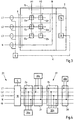
- Fig. 3 shows a switching matrix 2 and a measuring device 4, which are connected via a communication link 6.
- the measuring device 4 can also be part of the switching matrix 2.
- the measuring device 4 can also be arranged at a transfer point, for example in the form of a smart meter.
- inputs 8 are connected to outputs 10.
- the number of outputs 10 may be smaller than the number of inputs 8, in the present case there are two outputs A1 and A1 and three inputs L1, L2 and L3. But it is also possible that a third output 10 is present.
- a neutral conductor N can be looped through the switching matrix 2. The same applies to the protective conductor. In the case of a generator, the terminology can be reversed, then the outputs A1 and A2 are to be designated as inputs and the inputs L1, L2 and L3 as outputs.
- switches 12a-f are provided in the switching matrix.
- a switch 12 connects in each case an input L1, L2, L3 with an output A1, A2.
- the switches are driven by a processor 14.
- the processor is programmed so that in each case only the number of switches 12 is closed, which corresponds to the number of outputs A1, A2.
- an output A1, A2 is in each case more precisely connected only to an input L1, L2 or L3.
- the switches 12 are in communication with the processor 14.
- the processor is in communication with a communication device 16. Via the communication device 16, the measuring device 4 is connected to the switching matrix 2.
- the connection can be a Power Line Communication connection. Other possibilities of the connection are e.g. wireless connections. Any wired or wireless communication means and protocols are possible.
- the processor 14 operates the switches 12 such that a shift of the phase positions as in Fig. 2c shown is possible.
- the switches 12 switch such that a method as in Fig. 2c is shown is possible.
- the processor 14 receives information about a measurement from the measuring device 4 via the communication device 16. The processor 14 evaluates this information and controls the switches 12 so that asymmetries of an electrical variable on the phases L1, L2, L3 is counteracted.
- Fig. 4 shows by way of example a transfer point 18 on a local network 20, which can be understood as a low-voltage network or distribution network.
- an access network 22 is connected to the transfer point 18, which is, for example, a house distribution.
- the transfer point 18 can be arranged at the house connection point as well as in the house distribution box.
- a measuring device 4 is arranged.
- the power of each phase L1, L2, L3 can be determined.
- the phase position, current, the voltage and / or active and reactive power can be determined. Concretely, it is sufficient if at least one of these electrical variables, preferably the current intensity, is determined on the measuring device 4.
- a switching matrix 2a-d is provided on the subscriber network 22 for each of the subscribers 30a-d.
- the subscriber 30a can be, for example, a photovoltaic system operated at least in two phases.
- the subscriber 30c can be, for example, a battery storage operated at least in two phases, and the subscriber 30b can be, for example, an electric vehicle which is connected in three phases but can only charge in two phases.
- a connection to the earthing conductor and the protective conductor for each of the participants 30 is understood and is therefore not shown.
- a single-phase powered consumer 30d shown.
- the subscriber 30d is operated with 10 A, for example. First, it is assumed in the following example that the photovoltaic system 30a and the battery storage 30c are not in operation. By the operation of the subscriber 30d, a phase is charged with 10A.
- the switching matrix 2d switches the phase L1 to the output and thus connects the subscriber 30d with the phase L1, which is then loaded with 10A.
- the electric vehicle 30b which is operated in a two-phase manner, normally has to comply with the specifications regarding maximum load capacity and phase unbalance. It should be noted that for the sake of simplicity, only the electric vehicle is considered, which is usually not the single device that must comply with the requirement for symmetry, but compliance with the requirement applies to the sum of the equipment operated by a customer.
- the measuring device 4 again measures the size and determines that the phase L1 is loaded with 10 A, or that, as the case may be, the phases L3 and L2 are therefore less loaded than the phase L1.
- the switching matrix 2b is instructed to phase L3 and L2 to connect with the electric vehicle. In total, this meant that the three phases L1, L2, L3 were loaded as evenly as possible.
- the photovoltaic system 30a and the battery storage 30c are now also considered.
- the photovoltaic system 30a can feed in two phases.
- the measuring device 4 represents e.g. determine that the electrical load at phases L1 and L2 is highest, e.g. in which it is determined that the voltage at the phases L1 and L2 is lower than at the phase L3.
- the switching matrix 2a is therefore controlled or controls itself such that the switch connects a subscriber-side input to the phase L1 and connects the second subscriber-side input to the phase L2. This increases the voltages at these phases L1 and L2 and reduces the imbalance.
- the battery storage 30c can load on two phases.
- the two outputs of the battery store, which are applied to the inputs of the switching matrix 2c can be connected to two outputs of the switching matrix 2c, which are applied to the phases L1, L2 and L3. This is done in such a way that the two inputs of the switching matrix 2c are coupled to those two outputs of the switching matrix 2c such that the power of the battery memory is fed into two of the phases L1, L2, L3 in which the voltage is lowest.
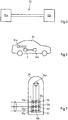
- Fig. 5 shows a charging cable 32 with two charging cable connectors 32a, 32b.
- a switching matrix 2 and / or a measuring device 4 may be integrated in the charging cable itself or in one of the charging cable plugs 32a, 32b.
- Fig. 6 shows an electric vehicle 34.
- a charge control circuit 34b can be fed via a charging socket 34a.
- the charge control circuit 34b can be operated, for example, two-phase.
- the charging socket 34a may be connected in three phases to a charging station.
- a switching matrix 2 may be connected in the vehicle 34 between the charging socket 34a and the charging control unit 34b. Depending on a measurement carried out, for example, in the switching matrix 2, two of the three input-side phases can be connected to the two outputs of the switching matrix 2.
- the charging station 36 may be connected on the input side with a switching matrix 2 to a distribution network 20.
- measuring devices 4 may be provided at the switching matrix 2 measuring devices 4 may be provided.
- the measuring devices can, for example, measure the voltage on the phases of the distribution network 20.
- the two phases with the highest voltages can be switched from the switching matrix 2 to the charging socket 36a.
- a third phase of the charging socket 36a may be switched blind, ie not connected to the distribution network 20. In this case, charging is only possible via two phases, whereby in each case the two phases are selected which are currently the least loaded in the network.
Claims (15)
- Procédé d'exploitation d'un consommateur pouvant fonctionner sur au moins une phase comprenant :- Mesure d'au moins une grandeur électrique sur au moins deux phases à l'entrée, du côté réseau d'abonné d'une matrice de commutation comportant au moins deux sorties, les entrées étant reliées à différentes phases d'un réseau,- Affectation d'au moins une entrée de la matrice de commutation à au moins une sortie de la matrice de commutation en fonction de la mesure, où, dans la matrice de commutation, au moins moins de sorties sont affectées à des entrées que d'entrées étant présentes, et où l'affectation de phases du réseau d'abonné à des phases individuelles de l'abonné est effectuée de manière sélective en fonction des informations concernant la grandeur mesurée,- et où la quantité électrique entre un réseau de distribution et un réseau d'abonné est mesurée par un compteur intelligent.
- Procédé d'exploitation d'un générateur électrique sur au moins une phase d'un réseau d'abonné comprenant :- Mesure d'au moins une grandeur électrique du réseau d'abonné, le réseau d'abonné étant relié à au moins deux phases différentes côté sortie d'une matrice de commutation comportant au moins deux sorties,- Affectation d'au moins une entrée de la matrice de commutation à au moins une sortie de la matrice de commutation en fonction de la mesure, où, dans la matrice de commutation, au moins moins d'entrées sont affectées à des sorties que de sorties étant présentes, et où l'affectation de phases du réseau d'abonné à des phases individuelles de l'abonné est effectuée de manière sélective en fonction des informations concernant la grandeur mesurée,- et où la quantité électrique entre un réseau de distribution et un réseau d'abonné est mesurée par un compteur intelligent.
- Procédé selon la revendication 1 ou 2, caractérisé
en ce que le consommateur ou générateur fonctionne sur exactement une phase et la matrice de commutation a exactement une sortie et/ou en ce que le consommateur fonctionne sur exactement deux phases et la matrice de commutation a exactement deux sortie et/ou en ce que le nombre de sorties est égal au nombre de phases avec lesquelles le consommateur ou générateur fonctionne et/ou en ce que le nombre d'entrées est égal au nombre de phases du réseau d'abonné. - Procédé selon l'une des revendications précédentes, caractérisé
en ce que l'au moins une grandeur électrique est mesurée en continu, de préférence de manière cyclique et/ou par intervalles, et en ce que l'affectation respective d'au moins une des entrées à une des sorties est effectuée en fonction de la mesure en cours. - Procédé selon l'une des revendications précédentes, caractérisé
en ce que l'affectation est modifiée en fonction de la mesure au cours du fonctionnement du consommateur ou du générateur et/ou en ce que l'affectation est effectuée en fonction de la mesure au début du fonctionnement du consommateur et/ou en ce que l'affectation du début du fonctionnement du consommateur ou du générateur reste inchangée pendant la durée de fonctionnement de l'abonné. - Procédé selon l'une des revendications précédentes, caractérisé
en ce que les entrées sont affectées l'une après l'autre, avec une amplitude croissante de la grandeur électrique mesurée, chacune à l'une des sorties. - Procédé selon l'une des revendications précédentes, caractérisé en ce que la grandeur électrique mesurée sur au moins une des phases est l'intensité du courant électrique à la phase respective et/ou le potentiel électrique de la phase respective et/ou la puissance électrique de la phase respective et/ou une différence de phase entre courant et tension à la phase respective.
- Procédé selon l'une des revendications précédentes, caractérisé en ce que des informations de fonctionnement pour le fonctionnement de la matrice de commutation sont transmises du dispositif de mesure à la matrice de commutation, en particulier en ce que les informations de fonctionnement sont transmises via le réseau d'abonné.
- Dispositif configuré pour faire fonctionner un consommateur électrique à au moins une phase, comprenant :- un dispositif de mesure configuré pour mesurer au moins une grandeur électrique sur au moins deux phases à l'entrée, du côté réseau d'abonné d'une matrice de commutation ayant au moins deux sorties,- Matrice de commutation configurée pour affecter au moins une entrée de la matrice de commutation à au moins une sortie de la matrice de commutation en fonction de la mesure, la matrice de commutation présentant au moins une sortie de moins par rapport aux entrées, et la matrice de commutation étant configurée de telle sorte que l'affectation des phases du réseau d'abonné aux phases individuelles de l'abonné se fait de manière sélective en fonction des informations concernant la grandeur mesurée,- le dispositif de mesure faisant partie d'un compteur intelligent et étant agencé au point de transfert entre le réseau de distribution et le réseau d'abonné.
- Dispositif selon la revendication 9,caractérisé
en ce que le dispositif de mesure et/ou la matrice de commutation sont intégrés dans le consommateur et/ou en ce que le dispositif de mesure et/ou la matrice de commutation sont formés spatialement séparés du consommateur, en particulier dans un boîtier propre. - Dispositif selon la revendication 9 ou 10, caractérisé
en ce que le dispositif de mesure et/ou la matrice de commutation est intégré(e) dans un dispositif de charge, un câble de charge ou une fiche de charge pour véhicules électriques et/ou en ce que le dispositif de mesure et/ou la matrice de commutation est intégré (e) dans un véhicule électrique. - Dispositif selon l'une quelconque des revendications 9 à 11, caractérisé
en ce que le dispositif de mesure et la matrice de commutation sont reliés entre eux de manière opérationnelle, en particulier en ce qu'une liaison de communication est établie entre le dispositif de mesure et la matrice de commutation. - Dispositif configuré pour faire fonctionner un générateur électrique sur au moins une phase d'un réseau d'abonné comprenant :- un dispositif de mesure configuré pour mesurer au moins une grandeur électrique du réseau d'abonné, le réseau d'abonné étant connecté à au moins deux phases côté sortie d'une matrice de commutation ayant au moins deux sorties,- Matrice de commutation agencée pour affecter au moins une entrée de la matrice de commutation à au moins une sortie de la matrice de commutation en fonction de la mesure, la matrice de commutation ayant au moins une sortie de plus que d'entrées, et la matrice de commutation étant agencée de telle sorte que l'affectation des phases du réseau d'abonné à des phases individuelles de l'abonné se fait de manière sélective en fonction des informations concernant la grandeur mesurée,- le dispositif de mesure faisant partie d'un compteur intelligent et étant agencé au point de transfert entre le réseau de distribution et le réseau d'abonné.
- Matrice de commutation agencée pour faire fonctionner un consommateur électrique pouvant être exploité sur au moins une phase, où :
la matrice de commutation présente au moins deux entrées pouvant être connectées à un réseau d'abonné et au moins deux sorties pouvant être connectées au consommateur et au moins une entrée de plus que de sorties, comprenant- un dispositif de réception configuré pour recevoir une information concernant une mesure d'au moins une grandeur électrique du réseau d'abonné, et- un dispositif de commutation configuré pour affecter au moins une des entrées à au moins une des sorties en fonction de l'information reçue, de telle sorte que l'affectation de phases du réseau d'abonné à des phases individuelles de l'abonné s'effectue sélectivement en fonction de l'information concernant la grandeur mesurée,- la quantité électrique entre un réseau de distribution et un réseau d'abonné étant mesurée par un compteur intelligent. - Matrice de commutation configurée pour faire fonctionner un générateur électrique pouvant être exploité sur au moins une phase d'un réseau d'abonné, où
la matrice de commutation présente au moins deux sorties pouvant être connectées au réseau d'abonné et au moins deux entrées pouvant être connectées au générateur, et au moins une sortie de plus que d'entrées, comprenant- un dispositif de réception agencé pour recevoir une information concernant une mesure d'au moins une grandeur électrique du réseau d'abonné, et
un dispositif de commutation configuré pour affecter au moins une des entrées à au moins une des sorties en fonction de l'information reçue, de telle sorte que l'affectation de phases du réseau d'abonné à des phases individuelles de l'abonné s'effectue sélectivement en fonction de l'information concernant la grandeur mesurée,- où la quantité électrique entre un réseau de distribution et un réseau d'abonné est mesurée par un compteur intelligent.
Priority Applications (1)
| Application Number | Priority Date | Filing Date | Title |
|---|---|---|---|
| PL15794540T PL3245702T3 (pl) | 2015-01-12 | 2015-11-11 | Sposób eksploatacji odbiornika elektrycznego lub generatora w sieci abonenckiej oraz matryca przełączająca |
Applications Claiming Priority (2)
| Application Number | Priority Date | Filing Date | Title |
|---|---|---|---|
| DE102015000076.4A DE102015000076A1 (de) | 2015-01-12 | 2015-01-12 | Verfahren zum Betreiben eines elektrischen Verbrauchers oder Erzeugers an einem Teilnehmernetz sowie eine Vorrichtung und eine Schaltmatrix |
| PCT/EP2015/076299 WO2016113015A1 (fr) | 2015-01-12 | 2015-11-11 | Procédé pour faire fonctionner un consommateur ou générateur électrique dans un réseau d'abonnés et matrice de commutation |
Publications (2)
| Publication Number | Publication Date |
|---|---|
| EP3245702A1 EP3245702A1 (fr) | 2017-11-22 |
| EP3245702B1 true EP3245702B1 (fr) | 2019-02-27 |
Family
ID=54542248
Family Applications (1)
| Application Number | Title | Priority Date | Filing Date |
|---|---|---|---|
| EP15794540.3A Active EP3245702B1 (fr) | 2015-01-12 | 2015-11-11 | Procédé pour faire fonctionner un consommateur ou générateur électrique dans un réseau d'abonnés et matrice de commutation |
Country Status (7)
| Country | Link |
|---|---|
| EP (1) | EP3245702B1 (fr) |
| DE (1) | DE102015000076A1 (fr) |
| DK (1) | DK3245702T3 (fr) |
| ES (1) | ES2727612T3 (fr) |
| HU (1) | HUE043471T2 (fr) |
| PL (1) | PL3245702T3 (fr) |
| WO (1) | WO2016113015A1 (fr) |
Cited By (2)
| Publication number | Priority date | Publication date | Assignee | Title |
|---|---|---|---|---|
| CN111688528A (zh) * | 2019-03-13 | 2020-09-22 | 台达电子工业股份有限公司 | 智能电流控制装置 |
| DE102021104573A1 (de) | 2021-02-25 | 2022-08-25 | KEBA Energy Automation GmbH | Vorrichtung, Ladestation, System und Verfahren |
Families Citing this family (8)
| Publication number | Priority date | Publication date | Assignee | Title |
|---|---|---|---|---|
| DE102017100138A1 (de) * | 2017-01-05 | 2018-07-05 | Envia Mitteldeutsche Energie Ag | Verfahren zum Betreiben eines Teilnehmers an einem Versorgungsnetz |
| DE102017201734B4 (de) | 2017-02-03 | 2018-09-13 | Volkswagen Aktiengesellschaft | Ladegerät und Verfahren zur Reduzierung der Schieflast eines zweiphasigen Ladegeräts |
| DE102017124288A1 (de) * | 2017-10-18 | 2019-04-18 | Innogy Se | Messung einer elektrischen Größe an einem Verbraucher in einem Wechselstromnetz |
| DE102018204779A1 (de) * | 2018-03-28 | 2019-10-02 | Bayerische Motoren Werke Aktiengesellschaft | Ladegerät |
| DE102018214747A1 (de) | 2018-08-30 | 2020-03-05 | Siemens Aktiengesellschaft | Einrichtung für einen Niederspannungsstromkreis |
| DE102019134380A1 (de) * | 2019-12-13 | 2021-06-17 | Sma Solar Technology Ag | Ladegerät für ein elektrofahrzeug, energieversorgungsanlage und verfahren zum betreiben eines derartigen ladegeräts |
| DE102019134384A1 (de) * | 2019-12-13 | 2021-06-17 | Sma Solar Technology Ag | Verfahren zum betreiben eines ladegeräts für ein elektrofahrzeug, ladegerät für ein elektrofahrzeug, energieversorgungsanlage mit einem derartigen ladegerät und energiemanagementeinrichtung zur verwendung bei dem verfahren |
| DE102019134379A1 (de) * | 2019-12-13 | 2021-06-17 | Sma Solar Technology Ag | Ladegerät für ein elektrofahrzeug, energieversorgungsanlage und verfahren zum laden eines elektrofahrzeugs mit einem ladegerät |
Family Cites Families (7)
| Publication number | Priority date | Publication date | Assignee | Title |
|---|---|---|---|---|
| KR101116681B1 (ko) * | 2007-02-20 | 2012-03-08 | 삼성전자주식회사 | 3상 전원의 상 불균형 방지회로 |
| EP2071693A3 (fr) * | 2007-12-12 | 2015-01-28 | Platinum GmbH | Procédé et circuit destinés à la commande de l'alimentation en énergie de plusieurs onduleurs monophasés dans un réseau multiphases |
| DE102009060364B4 (de) * | 2009-12-24 | 2023-04-13 | Volkswagen Ag | Vorrichtung und Verfahren zur Energieeinspeisung und/oder -rückspeisung von elektrischer Energie |
| US8587290B2 (en) * | 2011-03-29 | 2013-11-19 | General Electric Company | Method, system and device of phase identification using a smart meter |
| DE102011078047A1 (de) * | 2011-06-24 | 2012-12-27 | Siemens Aktiengesellschaft | Vorrichtung zur Steuerung der Belastung der Phasen eines dreiphasigen Energienetzes |
| DE102012208297A1 (de) * | 2012-05-16 | 2013-11-21 | Trilux Gmbh & Co. Kg | Stromversorgungsanordnung mit Phasenwahl für eine Leuchte |
| FR3006516A1 (fr) * | 2013-05-28 | 2014-12-05 | Commissariat Energie Atomique | Selection de phase pour installation electrique polyphasee |
-
2015
- 2015-01-12 DE DE102015000076.4A patent/DE102015000076A1/de not_active Withdrawn
- 2015-11-11 HU HUE15794540A patent/HUE043471T2/hu unknown
- 2015-11-11 ES ES15794540T patent/ES2727612T3/es active Active
- 2015-11-11 EP EP15794540.3A patent/EP3245702B1/fr active Active
- 2015-11-11 WO PCT/EP2015/076299 patent/WO2016113015A1/fr active Application Filing
- 2015-11-11 PL PL15794540T patent/PL3245702T3/pl unknown
- 2015-11-11 DK DK15794540.3T patent/DK3245702T3/da active
Non-Patent Citations (1)
| Title |
|---|
| None * |
Cited By (3)
| Publication number | Priority date | Publication date | Assignee | Title |
|---|---|---|---|---|
| CN111688528A (zh) * | 2019-03-13 | 2020-09-22 | 台达电子工业股份有限公司 | 智能电流控制装置 |
| CN111688528B (zh) * | 2019-03-13 | 2022-03-01 | 台达电子工业股份有限公司 | 智能电流控制装置 |
| DE102021104573A1 (de) | 2021-02-25 | 2022-08-25 | KEBA Energy Automation GmbH | Vorrichtung, Ladestation, System und Verfahren |
Also Published As
| Publication number | Publication date |
|---|---|
| EP3245702A1 (fr) | 2017-11-22 |
| HUE043471T2 (hu) | 2019-08-28 |
| DE102015000076A1 (de) | 2016-07-14 |
| DK3245702T3 (da) | 2019-05-20 |
| ES2727612T3 (es) | 2019-10-17 |
| WO2016113015A1 (fr) | 2016-07-21 |
| PL3245702T3 (pl) | 2019-08-30 |
Similar Documents
| Publication | Publication Date | Title |
|---|---|---|
| EP3245702B1 (fr) | Procédé pour faire fonctionner un consommateur ou générateur électrique dans un réseau d'abonnés et matrice de commutation | |
| EP3566276B1 (fr) | Procédé pour faire fonctionner un abonné d'un réseau d'alimentation | |
| EP2919352B1 (fr) | Procédé de fonctionnement d'un usager électrique, d'un point de mesure électrique sur un réseau d'usager électrique et usager électrique et point de mesure électrique | |
| EP2348597A1 (fr) | Adaptation de prestations partielles s'écoulant par le biais de chaque phase d'un courant alternatif multiphase | |
| DE102007030451B4 (de) | Stromversorgungsvorrichtung | |
| DE102013219528A1 (de) | Laden eines elektrischen Energiespeichers eines elektrisch antreibbaren Fahrzeugs | |
| DE102011078047A1 (de) | Vorrichtung zur Steuerung der Belastung der Phasen eines dreiphasigen Energienetzes | |
| EP2735468A2 (fr) | Procédé de charge d'une batterie de traction | |
| EP3501884A1 (fr) | Dispositif transformateur pour une station de charge destiné à la charge électrique de véhicules au moyen d'au moins deux points de charge | |
| EP3934931A1 (fr) | Station de charge pour charger des véhicules électriques | |
| DE102013204256A1 (de) | Ladevorrichtung für ein Elektrofahrzeug | |
| WO2018206201A1 (fr) | Dispositif de batterie comprenant au moins une ligne de modules, dans laquelle des unités modules sont branchées en série les unes derrière les autres, ainsi que véhicule à moteur et procédé de fonctionnement pour le dispositif de batterie | |
| EP3544145A1 (fr) | Procédé de charge des consommateurs électriques | |
| EP3576246A1 (fr) | Procédé de fonctionnement d'un système de charge à une pluralité de points de charge | |
| WO2013064377A2 (fr) | Unité d'alimentation et ensemble générateur et consommateur de courant | |
| DE102015105152A1 (de) | Anordnung und Verfahren zum Verringern einer Schieflast in einem dreiphasigen Verteilungsnetz | |
| DE102012100673A1 (de) | Vorrichtung zur elektrischen Energieeinspeisung aus einer dezentralen Eigenerzeugeranlage in ein Stromnetz | |
| EP3759783A1 (fr) | Dispositif de connexion d'un réseau partiel à un réseau à tension alternative et procédé de commande d'une sortie électrique | |
| DE102012110110A1 (de) | Wechselrichter, Verfahren zum Betreiben eines Wechselrichters und Energieversorgungsanlage mit einem Wechselrichter | |
| DE112022002486T5 (de) | Einstellung der umrichterklemmenspannung in leistungssystem | |
| WO2015104177A2 (fr) | Procédé et onduleur permettant d'alimenter un réseau de tension alternative en énergie électrique | |
| DE102019122922A1 (de) | Wechselstrom-Ladestation zum Laden von Elektrofahrzeugen | |
| EP3665756A1 (fr) | Dispositif de stockage d'énergie électrique | |
| DE102015001010A1 (de) | Energieübertragungssystem und Verfahren zu seinem Betrieb | |
| WO2012159663A1 (fr) | Dispositif d'alimentation électrique |
Legal Events
| Date | Code | Title | Description |
|---|---|---|---|
| STAA | Information on the status of an ep patent application or granted ep patent |
Free format text: STATUS: THE INTERNATIONAL PUBLICATION HAS BEEN MADE |
|
| PUAI | Public reference made under article 153(3) epc to a published international application that has entered the european phase |
Free format text: ORIGINAL CODE: 0009012 |
|
| STAA | Information on the status of an ep patent application or granted ep patent |
Free format text: STATUS: REQUEST FOR EXAMINATION WAS MADE |
|
| 17P | Request for examination filed |
Effective date: 20170407 |
|
| AK | Designated contracting states |
Kind code of ref document: A1 Designated state(s): AL AT BE BG CH CY CZ DE DK EE ES FI FR GB GR HR HU IE IS IT LI LT LU LV MC MK MT NL NO PL PT RO RS SE SI SK SM TR |
|
| AX | Request for extension of the european patent |
Extension state: BA ME |
|
| DAV | Request for validation of the european patent (deleted) | ||
| DAX | Request for extension of the european patent (deleted) | ||
| GRAP | Despatch of communication of intention to grant a patent |
Free format text: ORIGINAL CODE: EPIDOSNIGR1 |
|
| STAA | Information on the status of an ep patent application or granted ep patent |
Free format text: STATUS: GRANT OF PATENT IS INTENDED |
|
| INTG | Intention to grant announced |
Effective date: 20180912 |
|
| GRAS | Grant fee paid |
Free format text: ORIGINAL CODE: EPIDOSNIGR3 |
|
| GRAA | (expected) grant |
Free format text: ORIGINAL CODE: 0009210 |
|
| STAA | Information on the status of an ep patent application or granted ep patent |
Free format text: STATUS: THE PATENT HAS BEEN GRANTED |
|
| AK | Designated contracting states |
Kind code of ref document: B1 Designated state(s): AL AT BE BG CH CY CZ DE DK EE ES FI FR GB GR HR HU IE IS IT LI LT LU LV MC MK MT NL NO PL PT RO RS SE SI SK SM TR |
|
| REG | Reference to a national code |
Ref country code: GB Ref legal event code: FG4D Free format text: NOT ENGLISH |
|
| REG | Reference to a national code |
Ref country code: CH Ref legal event code: EP |
|
| REG | Reference to a national code |
Ref country code: AT Ref legal event code: REF Ref document number: 1102719 Country of ref document: AT Kind code of ref document: T Effective date: 20190315 |
|
| REG | Reference to a national code |
Ref country code: IE Ref legal event code: FG4D Free format text: LANGUAGE OF EP DOCUMENT: GERMAN |
|
| REG | Reference to a national code |
Ref country code: DE Ref legal event code: R096 Ref document number: 502015008168 Country of ref document: DE |
|
| REG | Reference to a national code |
Ref country code: NL Ref legal event code: FP |
|
| REG | Reference to a national code |
Ref country code: DK Ref legal event code: T3 Effective date: 20190516 |
|
| REG | Reference to a national code |
Ref country code: NO Ref legal event code: T2 Effective date: 20190227 |
|
| REG | Reference to a national code |
Ref country code: SE Ref legal event code: TRGR |
|
| REG | Reference to a national code |
Ref country code: LT Ref legal event code: MG4D |
|
| PG25 | Lapsed in a contracting state [announced via postgrant information from national office to epo] |
Ref country code: LT Free format text: LAPSE BECAUSE OF FAILURE TO SUBMIT A TRANSLATION OF THE DESCRIPTION OR TO PAY THE FEE WITHIN THE PRESCRIBED TIME-LIMIT Effective date: 20190227 Ref country code: FI Free format text: LAPSE BECAUSE OF FAILURE TO SUBMIT A TRANSLATION OF THE DESCRIPTION OR TO PAY THE FEE WITHIN THE PRESCRIBED TIME-LIMIT Effective date: 20190227 Ref country code: PT Free format text: LAPSE BECAUSE OF FAILURE TO SUBMIT A TRANSLATION OF THE DESCRIPTION OR TO PAY THE FEE WITHIN THE PRESCRIBED TIME-LIMIT Effective date: 20190627 |
|
| REG | Reference to a national code |
Ref country code: HU Ref legal event code: AG4A Ref document number: E043471 Country of ref document: HU |
|
| PG25 | Lapsed in a contracting state [announced via postgrant information from national office to epo] |
Ref country code: RS Free format text: LAPSE BECAUSE OF FAILURE TO SUBMIT A TRANSLATION OF THE DESCRIPTION OR TO PAY THE FEE WITHIN THE PRESCRIBED TIME-LIMIT Effective date: 20190227 Ref country code: GR Free format text: LAPSE BECAUSE OF FAILURE TO SUBMIT A TRANSLATION OF THE DESCRIPTION OR TO PAY THE FEE WITHIN THE PRESCRIBED TIME-LIMIT Effective date: 20190528 Ref country code: BG Free format text: LAPSE BECAUSE OF FAILURE TO SUBMIT A TRANSLATION OF THE DESCRIPTION OR TO PAY THE FEE WITHIN THE PRESCRIBED TIME-LIMIT Effective date: 20190527 Ref country code: HR Free format text: LAPSE BECAUSE OF FAILURE TO SUBMIT A TRANSLATION OF THE DESCRIPTION OR TO PAY THE FEE WITHIN THE PRESCRIBED TIME-LIMIT Effective date: 20190227 Ref country code: IS Free format text: LAPSE BECAUSE OF FAILURE TO SUBMIT A TRANSLATION OF THE DESCRIPTION OR TO PAY THE FEE WITHIN THE PRESCRIBED TIME-LIMIT Effective date: 20190627 Ref country code: LV Free format text: LAPSE BECAUSE OF FAILURE TO SUBMIT A TRANSLATION OF THE DESCRIPTION OR TO PAY THE FEE WITHIN THE PRESCRIBED TIME-LIMIT Effective date: 20190227 |
|
| REG | Reference to a national code |
Ref country code: SK Ref legal event code: T3 Ref document number: E 31134 Country of ref document: SK |
|
| REG | Reference to a national code |
Ref country code: ES Ref legal event code: FG2A Ref document number: 2727612 Country of ref document: ES Kind code of ref document: T3 Effective date: 20191017 |
|
| PG25 | Lapsed in a contracting state [announced via postgrant information from national office to epo] |
Ref country code: EE Free format text: LAPSE BECAUSE OF FAILURE TO SUBMIT A TRANSLATION OF THE DESCRIPTION OR TO PAY THE FEE WITHIN THE PRESCRIBED TIME-LIMIT Effective date: 20190227 Ref country code: AL Free format text: LAPSE BECAUSE OF FAILURE TO SUBMIT A TRANSLATION OF THE DESCRIPTION OR TO PAY THE FEE WITHIN THE PRESCRIBED TIME-LIMIT Effective date: 20190227 Ref country code: RO Free format text: LAPSE BECAUSE OF FAILURE TO SUBMIT A TRANSLATION OF THE DESCRIPTION OR TO PAY THE FEE WITHIN THE PRESCRIBED TIME-LIMIT Effective date: 20190227 |
|
| REG | Reference to a national code |
Ref country code: DE Ref legal event code: R097 Ref document number: 502015008168 Country of ref document: DE |
|
| PG25 | Lapsed in a contracting state [announced via postgrant information from national office to epo] |
Ref country code: SM Free format text: LAPSE BECAUSE OF FAILURE TO SUBMIT A TRANSLATION OF THE DESCRIPTION OR TO PAY THE FEE WITHIN THE PRESCRIBED TIME-LIMIT Effective date: 20190227 |
|
| PLBE | No opposition filed within time limit |
Free format text: ORIGINAL CODE: 0009261 |
|
| STAA | Information on the status of an ep patent application or granted ep patent |
Free format text: STATUS: NO OPPOSITION FILED WITHIN TIME LIMIT |
|
| 26N | No opposition filed |
Effective date: 20191128 |
|
| PG25 | Lapsed in a contracting state [announced via postgrant information from national office to epo] |
Ref country code: SI Free format text: LAPSE BECAUSE OF FAILURE TO SUBMIT A TRANSLATION OF THE DESCRIPTION OR TO PAY THE FEE WITHIN THE PRESCRIBED TIME-LIMIT Effective date: 20190227 |
|
| PG25 | Lapsed in a contracting state [announced via postgrant information from national office to epo] |
Ref country code: TR Free format text: LAPSE BECAUSE OF FAILURE TO SUBMIT A TRANSLATION OF THE DESCRIPTION OR TO PAY THE FEE WITHIN THE PRESCRIBED TIME-LIMIT Effective date: 20190227 |
|
| PG25 | Lapsed in a contracting state [announced via postgrant information from national office to epo] |
Ref country code: LU Free format text: LAPSE BECAUSE OF NON-PAYMENT OF DUE FEES Effective date: 20191111 Ref country code: MC Free format text: LAPSE BECAUSE OF FAILURE TO SUBMIT A TRANSLATION OF THE DESCRIPTION OR TO PAY THE FEE WITHIN THE PRESCRIBED TIME-LIMIT Effective date: 20190227 |
|
| PG25 | Lapsed in a contracting state [announced via postgrant information from national office to epo] |
Ref country code: IE Free format text: LAPSE BECAUSE OF NON-PAYMENT OF DUE FEES Effective date: 20191111 |
|
| PG25 | Lapsed in a contracting state [announced via postgrant information from national office to epo] |
Ref country code: CY Free format text: LAPSE BECAUSE OF FAILURE TO SUBMIT A TRANSLATION OF THE DESCRIPTION OR TO PAY THE FEE WITHIN THE PRESCRIBED TIME-LIMIT Effective date: 20190227 |
|
| PG25 | Lapsed in a contracting state [announced via postgrant information from national office to epo] |
Ref country code: MT Free format text: LAPSE BECAUSE OF FAILURE TO SUBMIT A TRANSLATION OF THE DESCRIPTION OR TO PAY THE FEE WITHIN THE PRESCRIBED TIME-LIMIT Effective date: 20190227 |
|
| PG25 | Lapsed in a contracting state [announced via postgrant information from national office to epo] |
Ref country code: MK Free format text: LAPSE BECAUSE OF FAILURE TO SUBMIT A TRANSLATION OF THE DESCRIPTION OR TO PAY THE FEE WITHIN THE PRESCRIBED TIME-LIMIT Effective date: 20190227 |
|
| PGFP | Annual fee paid to national office [announced via postgrant information from national office to epo] |
Ref country code: PL Payment date: 20221102 Year of fee payment: 8 Ref country code: BE Payment date: 20221118 Year of fee payment: 8 |
|
| PGFP | Annual fee paid to national office [announced via postgrant information from national office to epo] |
Ref country code: NL Payment date: 20231122 Year of fee payment: 9 |
|
| PGFP | Annual fee paid to national office [announced via postgrant information from national office to epo] |
Ref country code: SK Payment date: 20231102 Year of fee payment: 9 |
|
| PGFP | Annual fee paid to national office [announced via postgrant information from national office to epo] |
Ref country code: GB Payment date: 20231123 Year of fee payment: 9 |
|
| PGFP | Annual fee paid to national office [announced via postgrant information from national office to epo] |
Ref country code: ES Payment date: 20231215 Year of fee payment: 9 |
|
| PGFP | Annual fee paid to national office [announced via postgrant information from national office to epo] |
Ref country code: SE Payment date: 20231123 Year of fee payment: 9 Ref country code: NO Payment date: 20231121 Year of fee payment: 9 Ref country code: IT Payment date: 20231130 Year of fee payment: 9 Ref country code: HU Payment date: 20231110 Year of fee payment: 9 Ref country code: FR Payment date: 20231123 Year of fee payment: 9 Ref country code: DK Payment date: 20231122 Year of fee payment: 9 Ref country code: DE Payment date: 20231120 Year of fee payment: 9 Ref country code: CZ Payment date: 20231027 Year of fee payment: 9 Ref country code: CH Payment date: 20231201 Year of fee payment: 9 Ref country code: AT Payment date: 20231117 Year of fee payment: 9 |
|
| PGFP | Annual fee paid to national office [announced via postgrant information from national office to epo] |
Ref country code: PL Payment date: 20231102 Year of fee payment: 9 Ref country code: BE Payment date: 20231121 Year of fee payment: 9 |