EP3245484B1 - Capteurs inductifs de deplacement - Google Patents
Capteurs inductifs de deplacement Download PDFInfo
- Publication number
- EP3245484B1 EP3245484B1 EP16702185.6A EP16702185A EP3245484B1 EP 3245484 B1 EP3245484 B1 EP 3245484B1 EP 16702185 A EP16702185 A EP 16702185A EP 3245484 B1 EP3245484 B1 EP 3245484B1
- Authority
- EP
- European Patent Office
- Prior art keywords
- target
- transducer
- sensor
- patterns
- tot
- Prior art date
- Legal status (The legal status is an assumption and is not a legal conclusion. Google has not performed a legal analysis and makes no representation as to the accuracy of the status listed.)
- Active
Links
- 230000001939 inductive effect Effects 0.000 title claims description 106
- 238000004804 winding Methods 0.000 claims description 352
- 238000006073 displacement reaction Methods 0.000 claims description 130
- 230000000737 periodic effect Effects 0.000 claims description 22
- 238000005259 measurement Methods 0.000 description 87
- 238000001465 metallisation Methods 0.000 description 30
- 238000010586 diagram Methods 0.000 description 28
- 230000005284 excitation Effects 0.000 description 22
- 230000008901 benefit Effects 0.000 description 21
- 239000004020 conductor Substances 0.000 description 21
- 230000008878 coupling Effects 0.000 description 20
- 238000010168 coupling process Methods 0.000 description 20
- 238000005859 coupling reaction Methods 0.000 description 20
- 230000005672 electromagnetic field Effects 0.000 description 19
- 238000009826 distribution Methods 0.000 description 16
- 229910052751 metal Inorganic materials 0.000 description 16
- 239000002184 metal Substances 0.000 description 16
- 238000000034 method Methods 0.000 description 15
- 230000005405 multipole Effects 0.000 description 15
- 230000003071 parasitic effect Effects 0.000 description 15
- 230000006698 induction Effects 0.000 description 14
- WYTGDNHDOZPMIW-RCBQFDQVSA-N alstonine Natural products C1=CC2=C3C=CC=CC3=NC2=C2N1C[C@H]1[C@H](C)OC=C(C(=O)OC)[C@H]1C2 WYTGDNHDOZPMIW-RCBQFDQVSA-N 0.000 description 12
- 230000001965 increasing effect Effects 0.000 description 10
- 241001644893 Entandrophragma utile Species 0.000 description 8
- 230000036039 immunity Effects 0.000 description 8
- QEVHRUUCFGRFIF-MDEJGZGSSA-N reserpine Chemical compound O([C@H]1[C@@H]([C@H]([C@H]2C[C@@H]3C4=C(C5=CC=C(OC)C=C5N4)CCN3C[C@H]2C1)C(=O)OC)OC)C(=O)C1=CC(OC)=C(OC)C(OC)=C1 QEVHRUUCFGRFIF-MDEJGZGSSA-N 0.000 description 8
- 230000004044 response Effects 0.000 description 8
- 230000003750 conditioning effect Effects 0.000 description 7
- 230000000694 effects Effects 0.000 description 7
- 230000008859 change Effects 0.000 description 6
- 230000000295 complement effect Effects 0.000 description 6
- 230000026683 transduction Effects 0.000 description 6
- 238000010361 transduction Methods 0.000 description 6
- 230000007423 decrease Effects 0.000 description 5
- XEEYBQQBJWHFJM-UHFFFAOYSA-N Iron Chemical compound [Fe] XEEYBQQBJWHFJM-UHFFFAOYSA-N 0.000 description 4
- 241000897276 Termes Species 0.000 description 4
- 239000002131 composite material Substances 0.000 description 4
- 239000011231 conductive filler Substances 0.000 description 4
- 230000004048 modification Effects 0.000 description 4
- 238000012986 modification Methods 0.000 description 4
- 238000003672 processing method Methods 0.000 description 4
- 238000013519 translation Methods 0.000 description 4
- 230000017105 transposition Effects 0.000 description 4
- 229910000831 Steel Inorganic materials 0.000 description 3
- 230000001133 acceleration Effects 0.000 description 3
- 230000006978 adaptation Effects 0.000 description 3
- 238000013459 approach Methods 0.000 description 3
- 230000001808 coupling effect Effects 0.000 description 3
- 230000007547 defect Effects 0.000 description 3
- 238000013461 design Methods 0.000 description 3
- 238000001914 filtration Methods 0.000 description 3
- 238000009472 formulation Methods 0.000 description 3
- 238000004519 manufacturing process Methods 0.000 description 3
- 239000000203 mixture Substances 0.000 description 3
- 230000009467 reduction Effects 0.000 description 3
- 239000010959 steel Substances 0.000 description 3
- 230000001360 synchronised effect Effects 0.000 description 3
- 238000012360 testing method Methods 0.000 description 3
- RYGMFSIKBFXOCR-UHFFFAOYSA-N Copper Chemical compound [Cu] RYGMFSIKBFXOCR-UHFFFAOYSA-N 0.000 description 2
- 101100028037 Salmonella typhimurium (strain LT2 / SGSC1412 / ATCC 700720) prlC gene Proteins 0.000 description 2
- 229910052782 aluminium Inorganic materials 0.000 description 2
- XAGFODPZIPBFFR-UHFFFAOYSA-N aluminium Chemical compound [Al] XAGFODPZIPBFFR-UHFFFAOYSA-N 0.000 description 2
- 238000010276 construction Methods 0.000 description 2
- 229910052802 copper Inorganic materials 0.000 description 2
- 239000010949 copper Substances 0.000 description 2
- 230000003247 decreasing effect Effects 0.000 description 2
- 229910052742 iron Inorganic materials 0.000 description 2
- 239000000463 material Substances 0.000 description 2
- 244000045947 parasite Species 0.000 description 2
- 238000012545 processing Methods 0.000 description 2
- 230000004224 protection Effects 0.000 description 2
- 230000035939 shock Effects 0.000 description 2
- 239000007787 solid Substances 0.000 description 2
- 208000031968 Cadaver Diseases 0.000 description 1
- 239000004593 Epoxy Substances 0.000 description 1
- 241000333074 Eucalyptus occidentalis Species 0.000 description 1
- 239000006096 absorbing agent Substances 0.000 description 1
- 238000004026 adhesive bonding Methods 0.000 description 1
- 238000004458 analytical method Methods 0.000 description 1
- 230000002238 attenuated effect Effects 0.000 description 1
- 238000006243 chemical reaction Methods 0.000 description 1
- 230000001143 conditioned effect Effects 0.000 description 1
- 239000000470 constituent Substances 0.000 description 1
- 238000000354 decomposition reaction Methods 0.000 description 1
- 239000003989 dielectric material Substances 0.000 description 1
- 238000005553 drilling Methods 0.000 description 1
- 238000010292 electrical insulation Methods 0.000 description 1
- 238000005516 engineering process Methods 0.000 description 1
- 238000005530 etching Methods 0.000 description 1
- 238000002847 impedance measurement Methods 0.000 description 1
- 230000003993 interaction Effects 0.000 description 1
- 238000003754 machining Methods 0.000 description 1
- 238000000465 moulding Methods 0.000 description 1
- 238000012805 post-processing Methods 0.000 description 1
- 230000008569 process Effects 0.000 description 1
- 238000011084 recovery Methods 0.000 description 1
- 230000002040 relaxant effect Effects 0.000 description 1
- 229920006395 saturated elastomer Polymers 0.000 description 1
- 230000035945 sensitivity Effects 0.000 description 1
- 238000005245 sintering Methods 0.000 description 1
- 230000002459 sustained effect Effects 0.000 description 1
- 230000002123 temporal effect Effects 0.000 description 1
- 238000009827 uniform distribution Methods 0.000 description 1
- 230000000007 visual effect Effects 0.000 description 1
- 230000002747 voluntary effect Effects 0.000 description 1
Images


Classifications
-
- G—PHYSICS
- G01—MEASURING; TESTING
- G01D—MEASURING NOT SPECIALLY ADAPTED FOR A SPECIFIC VARIABLE; ARRANGEMENTS FOR MEASURING TWO OR MORE VARIABLES NOT COVERED IN A SINGLE OTHER SUBCLASS; TARIFF METERING APPARATUS; MEASURING OR TESTING NOT OTHERWISE PROVIDED FOR
- G01D5/00—Mechanical means for transferring the output of a sensing member; Means for converting the output of a sensing member to another variable where the form or nature of the sensing member does not constrain the means for converting; Transducers not specially adapted for a specific variable
- G01D5/12—Mechanical means for transferring the output of a sensing member; Means for converting the output of a sensing member to another variable where the form or nature of the sensing member does not constrain the means for converting; Transducers not specially adapted for a specific variable using electric or magnetic means
- G01D5/14—Mechanical means for transferring the output of a sensing member; Means for converting the output of a sensing member to another variable where the form or nature of the sensing member does not constrain the means for converting; Transducers not specially adapted for a specific variable using electric or magnetic means influencing the magnitude of a current or voltage
- G01D5/20—Mechanical means for transferring the output of a sensing member; Means for converting the output of a sensing member to another variable where the form or nature of the sensing member does not constrain the means for converting; Transducers not specially adapted for a specific variable using electric or magnetic means influencing the magnitude of a current or voltage by varying inductance, e.g. by a movable armature
- G01D5/204—Mechanical means for transferring the output of a sensing member; Means for converting the output of a sensing member to another variable where the form or nature of the sensing member does not constrain the means for converting; Transducers not specially adapted for a specific variable using electric or magnetic means influencing the magnitude of a current or voltage by varying inductance, e.g. by a movable armature by influencing the mutual induction between two or more coils
- G01D5/2053—Mechanical means for transferring the output of a sensing member; Means for converting the output of a sensing member to another variable where the form or nature of the sensing member does not constrain the means for converting; Transducers not specially adapted for a specific variable using electric or magnetic means influencing the magnitude of a current or voltage by varying inductance, e.g. by a movable armature by influencing the mutual induction between two or more coils by a movable non-ferromagnetic conductive element
-
- G—PHYSICS
- G01—MEASURING; TESTING
- G01B—MEASURING LENGTH, THICKNESS OR SIMILAR LINEAR DIMENSIONS; MEASURING ANGLES; MEASURING AREAS; MEASURING IRREGULARITIES OF SURFACES OR CONTOURS
- G01B7/00—Measuring arrangements characterised by the use of electric or magnetic techniques
- G01B7/003—Measuring arrangements characterised by the use of electric or magnetic techniques for measuring position, not involving coordinate determination
-
- G—PHYSICS
- G01—MEASURING; TESTING
- G01D—MEASURING NOT SPECIALLY ADAPTED FOR A SPECIFIC VARIABLE; ARRANGEMENTS FOR MEASURING TWO OR MORE VARIABLES NOT COVERED IN A SINGLE OTHER SUBCLASS; TARIFF METERING APPARATUS; MEASURING OR TESTING NOT OTHERWISE PROVIDED FOR
- G01D5/00—Mechanical means for transferring the output of a sensing member; Means for converting the output of a sensing member to another variable where the form or nature of the sensing member does not constrain the means for converting; Transducers not specially adapted for a specific variable
- G01D5/12—Mechanical means for transferring the output of a sensing member; Means for converting the output of a sensing member to another variable where the form or nature of the sensing member does not constrain the means for converting; Transducers not specially adapted for a specific variable using electric or magnetic means
- G01D5/14—Mechanical means for transferring the output of a sensing member; Means for converting the output of a sensing member to another variable where the form or nature of the sensing member does not constrain the means for converting; Transducers not specially adapted for a specific variable using electric or magnetic means influencing the magnitude of a current or voltage
- G01D5/20—Mechanical means for transferring the output of a sensing member; Means for converting the output of a sensing member to another variable where the form or nature of the sensing member does not constrain the means for converting; Transducers not specially adapted for a specific variable using electric or magnetic means influencing the magnitude of a current or voltage by varying inductance, e.g. by a movable armature
- G01D5/204—Mechanical means for transferring the output of a sensing member; Means for converting the output of a sensing member to another variable where the form or nature of the sensing member does not constrain the means for converting; Transducers not specially adapted for a specific variable using electric or magnetic means influencing the magnitude of a current or voltage by varying inductance, e.g. by a movable armature by influencing the mutual induction between two or more coils
- G01D5/2046—Mechanical means for transferring the output of a sensing member; Means for converting the output of a sensing member to another variable where the form or nature of the sensing member does not constrain the means for converting; Transducers not specially adapted for a specific variable using electric or magnetic means influencing the magnitude of a current or voltage by varying inductance, e.g. by a movable armature by influencing the mutual induction between two or more coils by a movable ferromagnetic element, e.g. a core
-
- G—PHYSICS
- G01—MEASURING; TESTING
- G01P—MEASURING LINEAR OR ANGULAR SPEED, ACCELERATION, DECELERATION, OR SHOCK; INDICATING PRESENCE, ABSENCE, OR DIRECTION, OF MOVEMENT
- G01P3/00—Measuring linear or angular speed; Measuring differences of linear or angular speeds
- G01P3/42—Devices characterised by the use of electric or magnetic means
- G01P3/44—Devices characterised by the use of electric or magnetic means for measuring angular speed
- G01P3/49—Devices characterised by the use of electric or magnetic means for measuring angular speed using eddy currents
-
- G—PHYSICS
- G01—MEASURING; TESTING
- G01P—MEASURING LINEAR OR ANGULAR SPEED, ACCELERATION, DECELERATION, OR SHOCK; INDICATING PRESENCE, ABSENCE, OR DIRECTION, OF MOVEMENT
- G01P3/00—Measuring linear or angular speed; Measuring differences of linear or angular speeds
- G01P3/42—Devices characterised by the use of electric or magnetic means
- G01P3/50—Devices characterised by the use of electric or magnetic means for measuring linear speed
- G01P3/505—Devices characterised by the use of electric or magnetic means for measuring linear speed by using eddy currents
Definitions
- the present application relates to the field of inductive measurement of displacement of a mechanical part relative to another.
- inductive measurement is meant here the measurement of alternating electromagnetic fields, by means of electric windings.
- the present application relates to the technical subdomain of eddy current sensors, in which an electromagnetic field generated by an inductor is established in a different manner depending on the presence and arrangement of moving conductive parts (relative to to the inductor) near the inductor.
- Such electromagnetic phenomena become exploitable for instrumentation purposes when certain electric frequencies of the electromagnetic field take sufficiently large values, this notion of importance being conditioned by several parameters such as the geometrical dimensions of the conductive parts, their electrical and magnetic properties, their temperature, etc.
- displacement measurement is meant here the estimation of information relating to the position, the speed, the acceleration or any other quantity characteristic of the displacements of the conductive part with respect to the inductor or to the reference frame of the inductor.
- displacements one considers at the same time the angular displacements (rotation about an axis), linear displacements (translation along an axis), or any combination of such displacements between them or along disjoint axes. More particularly, but not exclusively, the present application relates to the technical subdomains of inductive position sensors, inductive speed sensors and / or inductive acceleration sensors.
- An inductive displacement sensor typically comprises a transducer (for example integral with a measurement reference frame, also called a frame), and a target (for example secured to a movable mechanical part with respect to the measurement reference frame).
- the target is placed away from the transducer, and is not in contact (mechanically or electrically) with the transducer (non-contact measurement).
- the transducer comprises a primary winding, or inductor, adapted to produce an alternating electromagnetic field, and at least one secondary winding across which is induced an alternating voltage, also called electromotive force or EMF, in the presence of the electromagnetic field produced by the winding. primary.
- the target is a partially or totally conductive element, also called a coupling armature, whose presence and / or displacement in front of the transducer modifies the coupling between the primary winding and the secondary winding. Note that the effect of the target on the coupling between the primary winding and the secondary winding depends on the position of the target relative to the transducer, but also on its speed relative to the transducer.
- the electromagnetic field distribution is thus shaped spatially according to the position and the relative displacement of the target with respect to the transducer.
- the spatial distribution of the electromagnetic field evolves, and thus the EMF induced in the secondary winding evolves as well.
- the EMF analysis induced, at the terminals of the secondary winding, by the electromagnetic field produced by the primary winding, makes it possible to estimate the position and / or the displacement of the target with respect to the secondary winding of the transducer. More particularly, but not exclusively, the temporal variations in the amplitude of the EMF across the secondary winding make it possible to estimate the position, the speed and / or the acceleration of the target with respect to the transducer.
- a preferred example of such a method is to perform a synchronous demodulation of the electromotive force (modulated) by a synchronous signal of the excitation frequency, and whose electrical phase has been chosen to meet particular criteria, for example to maximize the signal obtained at the demodulation output.
- An alternative method consists in calculating the signal module after synchronous demodulation, which has the advantage and the disadvantage of not fixing an electrical phase of demodulation. It is also specified that the amplitude of the electromotive force is a preferred measurement variable for the implementation of a displacement measurement with the sensors of the invention, but that it is by no means exclusive of other electrical quantities of measurement such as the phase, the frequency, or the secondary electrical power when a load of finite value is connected at the terminals of the secondary winding (adaptation of charge).
- Inductive displacement sensors known have various disadvantages.
- the known sensors are relatively sensitive to mounting inaccuracies (off-center, tilt and / or target distance / transducer), as well as to the presence of conductive parts near the measurement zone, which poses a problem for an operation. industrial. Problems related to the lack of linearity of the sensor response may also arise.
- the accuracy and robustness of the estimate of position and / or displacement of the target in the known sensors should be improved.
- a disadvantage of known sensors is that they are relatively fragile, which is a problem in some types of application, especially in industrial settings.
- an embodiment provides a target for an inductive displacement sensor, comprising a plurality of conductive patterns distributed along an area of dimension D tot in one direction, said patterns being defined by the superposition of at least a first set of periodic elementary patterns of period approximately equal to D tot / N, comprising N first elementary conductive patterns of dimension approximately equal to D tot / 2N in said direction, regularly distributed along said zone, and a second set of elementary periodic patterns of period approximately equal to D tot / (N + r), comprising N + r second motifs elementary elements approximately equal to D tot / 2 (N + r) in said direction, regularly distributed along said zone, where N is an integer greater than or equal to 2 and r is a positive integer, nonzero and less than or equal to at N-1, wherein first and second elementary conductor patterns overlap at least partially.
- the first and second elementary conductive patterns respectively have the form of portions of first and second superposed strips parallel to said direction.
- the first and second strips are of approximately identical widths.
- the first and second bands are of distinct widths, the first band being at least twice as wide as the second band.
- N is an even number.
- said patterns are defined by the superimposition of the first and second sets of periodic elementary patterns, and a third set of periodic elementary patterns of period approximately equal to D tot / (N + r), comprising N + r third elementary patterns of dimension approximately equal to D tot / 2 (N + r) in said direction regularly distributed along said area with an offset of approximately D tot / 2 (N + r) with respect to the elementary patterns of the second set of periodic patterns, first and third elementary conductive patterns overlapping at least partially.
- the first, second and third elementary patterns respectively have the form of portions of first, second and third strips parallel to said direction, the first and second strips on the one hand and the first and third strips on the other being superimposed, and the second and third strips being approximately the same width less than the width of the first band.
- the direction is a circular direction.
- the dimension D tot is an angular dimension equal to 360 °.
- r is equal to 1.
- a transducer for an inductive displacement sensor comprising: a primary winding; a first set of at least two secondary windings each having N first turns of the same winding direction or 2N alternating first winding turns, regularly distributed along an area of dimension D tot in one direction, each first coil having a dimension in said direction approximately equal to D tot / 2N; and a second set of at least two secondary windings each having N + r second turns of the same winding direction or 2 (N + r) alternating second winding turns, regularly distributed along said zone, each second winding coil having a dimension in said direction approximately equal to D tot / 2 (N + r), where N is an integer greater than or equal to 2 and r is a positive integer, nonzero and less than or equal to N-1, wherein first and second turns overlap at least partially.
- the first and second turns respectively have the form of first and second superimposed strip portions parallel to said direction.
- the transducer further comprises a third set of at least two secondary windings each comprising N + r third turns of the same winding direction or 2 (N + r) alternating turns of winding direction, regularly distributed along said zone with an offset of approximately D tot / 2 (N + r) with respect to the second set, each third turn having a dimension approximately equal to D tot / 2 (N + r) in said direction, and first and second turns overlapping at least partially.
- the first, second and third turns respectively have the form of portions of first, second and third strips parallel to said direction, the first and second strips being superimposed and the first and third strips being superimposed.
- the second and third secondary windings are connected in series.
- the series connection point of the second and third secondary windings is connected to an electrical connection terminal.
- Another embodiment provides an inductive displacement sensor, comprising a transducer of the aforementioned type, and a target of the aforementioned type.
- angular displacement sensors and more specifically angular displacement sensors of approximately general planar shape, for example sensors having a generally disk-like shape, or, more generally, sensors having a shape circular annular band of angular opening less than or equal to 360 °.
- inductive displacement sensors for example inductive displacement sensors. linear type of the type described in the patent EP0182085 above.
- the adaptation of the examples and embodiments described in the present application to other types of inductive displacement sensors is within the abilities of those skilled in the art and will therefore not be detailed below.
- the inductive sensors described in the present application and illustrated in the figures have characteristic dimensions (diameter for the angular sensors and width for the linear sensors) of between 5 mm and 200 mm, and of preferably between 40 mm and 50 mm.
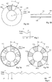
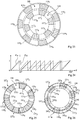
- FIGS. 1A and 1B are respectively a front view and a side view schematically showing an example of an inductive sensor 100 angular position of the planar type, having a general shape of disc.
- the sensor 100 comprises a transducer 110 having a primary conductive winding 101 and a secondary conductive winding 103.
- the primary winding 101 comprises two coils or conductive loops 101a and 101b approximately circular, concentric and coplanar, of opposite winding directions and distinct radii.
- Each turn 101a, 101b of the primary winding 101 comprises at least one turn, and preferably several turns.
- the turns 101a and 101b are preferably connected in series so as to be traversed by currents of the same intensity but of opposite flow directions, but may optionally be connected in parallel so as to see the same voltage at their terminals (preferably applied so that the flow directions of the current in the two turns are opposite).
- the primary winding 101 may comprise a single turn (one or more turns). More generally, the primary winding 101 may comprise one or more concentric turns (at one or more turns each) arranged so as to generate an electromagnetic field in the zone of measurement of the transducer. The described embodiments are not limited to these particular arrangements of the primary winding.
- the secondary winding 103 consists of a coil or conductive loop disposed in the circular annular band-shaped space between the turns 101a and 101b.
- the winding 103 is for example located approximately in the same plane as the turns 101a and 101b, or in a substantially parallel plane.
- the turn 103 substantially follows the contour of an angular sector of angular aperture ⁇ of the annular band delimited by the turns 101a and 101b.
- the turn 103 comprises in particular radial portions and ortho-radial portions of the contour of the annular band portion.
- Such a winding allows an angular position measurement over a range of ⁇ °.
- the angular aperture ⁇ of the turn 103 is approximately equal to 30 °.
- the angle ⁇ can take any value between 0 and 180 °.
- the turn 103 preferably comprises a single turn but may optionally include several turns.
- the primary 101 and secondary windings 103 are for example arranged in and on the same dielectric support (not shown) in the form of a plate of a few hundred micrometers to a few millimeters in thickness, for example a PCB type circuit board support (from the English "Printed Circuit Board").
- the sensor 100 further comprises a target 111 comprising a conductive pattern 107, located at a non-zero distance from the transducer and adapted to move relative to the transducer.
- a target 111 comprising a conductive pattern 107, located at a non-zero distance from the transducer and adapted to move relative to the transducer.
- the conductive pattern 107 of the target 111 has substantially the same shape as the annular band portion delimited by the pattern of the coil 103 of the transducer.
- the target is rotatably mounted about an axis Z orthogonal to the transducer plane passing through the center of the turns 101a and 101b, so that when the target rotates by an angle 2 ⁇ about the Z axis, the target conductive pattern 107 (angular aperture a), approximately completely covers and then discovers approximately the entire surface of the annular band delimited by the turn of the secondary winding 103 of the transducer.
- the target may consist of a plate made of a dielectric material, for example in the form of a disc, of which a face turned towards the transducer is partially coated with a layer of a conductive, magnetic or no, for example a metal layer, for example a layer of iron, steel, aluminum, copper, etc., forming the conductive pattern 107.
- the target may consist solely of a portion of metal plate cut to the shape of the conductive pattern 107, mounted by any means adapted to be rotatable relative to the transducer above the annular band portion delimited by the turns 101a and 101b.
- the circulation of an alternating current Ip in the primary winding 101 is applied by electrical means.
- the circulation of the current Ip in the winding 101 produces an electromagnetic field B having, in the absence of a target, a distribution substantially symmetrical by revolution in the circular annular band traversed by the secondary winding 103.
- the frequency of the alternating current of excitation Ip imposed in the primary winding is between 500 kHz and 50 MHz (eg 4 MHz).
- the amplitude of the current Ip is for example between 0.1 mA and 100 mA (for example 2 mA).
- the secondary winding 103 provides between its ends an alternating EMF V of frequency substantially equal to the excitation frequency of the primary winding, and a priori non-zero amplitude.
- the conductive pattern 107 of the target 111 covers all or part of the secondary winding 103, the spatial distribution of the electromagnetic field in the vicinity of the turn 103 changes as a function of the arrangement and displacement of the surface portion of the conductive pattern.
- Another formulation consists in considering that under the effect of the magnetic excitation generated by the circulation of the current Ip in the primary winding, eddy currents appear in the conductive pattern 107, causing a modification of the spatial distribution of the electromagnetic field according to the disposition and displacement of the surface portion of the pattern 107 located opposite the turn 103.
- These changes or variations in the spatial distribution of the electromagnetic field depending on the disposition and displacement of the the surface portion of the pattern 107 situated opposite the turn 103 is translated, by induction, by variations or changes in the amplitude V of the envelope of the voltage across the secondary winding, a function of the arrangement and displacement of the surface portion of the pattern 107 situated opposite the turn 103.
- the surface of the portion of the conductive pattern 107 located opposite the turn 103 increases when the angular position ⁇ increases, then, for the angular positions ⁇ ranging from 0 ° to ⁇ °, the surface of the portion of the conductive pattern 107 opposite the turn 103 decreases when the angular position ⁇ increases.
- the surface of the portion of the conductive pattern 107 facing the turn of the secondary winding 103 is zero, and the position and / or the displacement of the target 111 relative to the transducer can not be measured.
- the signal V is therefore theoretically a triangular signal varying linearly between V min and V max over the angular range from - ⁇ ° to ⁇ °. It will be seen below that in practice, the signal V has areas of non-linearity and consequently has a sinusoidal shape.
- the measurement of the amplitude V of the envelope the electromotive force at the terminals of the secondary winding 103 makes it possible to determine the angular position ⁇ of the target with respect to the transducer.
- the measurement of the signal V does not make it possible to discriminate the position values of the range from - ⁇ ° to 0 ° of the position values of the range from 0 ° to ⁇ ° (non-surjective measurement ).
- the extent of the range of angular positions that can effectively be measured by the sensor 100 is therefore approximately equal to ⁇ °, provided that the angle ⁇ does not exceed 180 °.
- the Figures 3A and 3B are front views schematically showing another example of an inductive angular position sensor having a general disc shape.
- This sensor comprises a transducer 112 represented in figure 3A and a target 114 represented in figure 3B .
- Target 114 of the figure 3B differs from the target 111 of the Figure 1A mainly by its conductive pattern.
- the target 114 of the figure 3B differs from the target 111 of the Figure 1A in that it no longer comprises a single conductive pattern 107, but a set of N conductive patterns 117 i integral with the target, and adapted to move relative to the transducer, N being an integer greater than or equal to 2 and i being an integer ranging from 1 to N.
- the transducer 112 of the figure 3A differs from the transducer 110 of the Figure 1A mainly by the shape of its secondary winding 113.
- the secondary winding 113 of the transducer 112 of the figure 3A no longer includes a single conductive turn, but a set of N turns 113 i .
- Target 114 of the figure 3B is intended to be rotatably mounted relative to the transducer 112 of the figure 3A , similar or identical to what has been described in relation to the Figures 1A and 1B .
- the set of conductive patterns 117 i and the set of turns 113 i consist of the repetition by revolution of N substantially identical patterns, respectively 117 i and 113 i .
- the repetition by revolution of these patterns is carried out with a spatial periodicity of 2 ⁇ , that is to say that each angular aperture pattern substantially equal to ⁇ ° is spaced from its nearest neighbor by a portion of empty circular annular band of ortho-radial extent substantially equal to ⁇ °.
- the transducer of the figure 3A comprises a secondary winding 113 comprising N loops or turns 113 i in series.
- the N turns 113 i are evenly distributed along the 360 ° of the circular annular band approximately delimited by the turns 101a and 101b of the primary winding 101, that is to say that two turns 113 i consecutive winding secondary are separated by an annular band portion of angle approximately equal to ⁇ .
- the target of the figure 3B comprises N conductive patterns 117 i .
- the N conductive patterns 117 i are regularly distributed along an annular band of the target intended to be positioned facing the annular band of the transducer containing the turns 113 i .
- a multipole sensor will be defined as a sensor in which an elementary conductive pattern is regularly repeated at least twice on the target in a direction parallel to a degree of freedom of movement of the target with respect to the transducer (i.e. in orthoradial direction in an angular sensor of the type described above).
- a multipole inductive sensor has a measurement range of ⁇ ° equal to half of its electrical period of 2 ⁇ °.
- the electrical period is 360 °, and the measuring range is approximately half the electrical period, 180 °.
- the figure 4 is a diagram representing the evolution of the amplitude V of the envelope of the electromotive force at the terminals of the secondary winding 113 of the sensor of the Figures 3A and 3B according to the angular position ⁇ of the target relative to the transducer.
- the signal V varies periodically between a high value V max and a low value V min , with an angular period of variation approximately equal to the electrical period 2 ⁇ of the sensor.
- the amplitude of the range of angular positions ⁇ that can be measured by the sensor of Figures 3A and 3B is approximately equal to half of the electrical period, ie ⁇ °.
- An advantage of the sensor Figures 3A and 3B compared to the sensor Figures 1A and 1B is that the larger number of patterns distributed on the target and on the transducer allows a measurement distributed over an extended measurement zone, in which each pattern contributes locally and constructively to the generation of a global electromotive force, this electromotive force being more immune to positioning errors of the target relative to the transducer than in the sensor of Figures 1A and 1B wherein the measurement made is a local measurement made using a single set of patterns 107-103.
- This robustness of the measurement is all the more important as the number N of pairs of poles of the sensor is high.
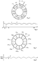
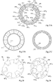
- the figure 5 illustrates an alternative embodiment of the sensor of Figures 3A and 3B .
- the transducer of the sensor has been shown, the target being identical to that of the figure 3B .
- the sensor transducer of the figure 5 includes the same elements as the transducer of the figure 3A and further comprises a second secondary winding 113 'comprising N loops or turns 113 i ' in series.
- a second secondary winding 113 'comprising N loops or turns 113 i ' in series For the sake of clarity, the connections between the different loops 113 i of the winding 113 and the connections between the different loops 113 i 'of the winding 113' have not been represented on the figure 5 .
- the secondary winding 113 ' (shown in broken lines) is substantially identical to the secondary winding 113 (shown in solid lines), and is arranged in the same band annular transducer that the secondary winding 113, with an angular offset corresponding to a quarter of the electrical period of the sensor, that is approximately equal to ⁇ / 2, relative to the secondary winding 113.
- the figure 6 is a diagram representing the evolution of the amplitude V (solid line) of the envelope of the electromotive force across the secondary winding 113 of the sensor of the figure 5 , and the evolution of the amplitude V '(in broken lines) of the envelope of the electromotive force across the secondary winding 113' of the sensor of the figure 5 , as a function of the angular position ⁇ of the target relative to the transducer.
- the signals V and V 'vary periodically between a high value V max and a low value V min , with a period of equal variation at the electrical period of the sensor, that is to say approximately equal to 2 ⁇ ° in this example, and with an angular offset with respect to each other substantially equal to a quarter of the electrical period of the sensor, c ' that is, approximately ⁇ / 2 ° in this example.
- An advantage of the transducer of the figure 5 compared to the transducer of the figure 3A is that it makes it possible to extend the range of angular positions ⁇ that can be measured by the sensor up to approximately an entire electrical period (ie 2 ⁇ °), instead of half a period (c that is, ⁇ °) in the example of Figures 3A and 3B .
- the figure 7 illustrates another variant embodiment of the sensor of Figures 3A and 3B .
- the transducer of the sensor has been shown, the target being identical to that of the figure 3B .
- the sensor transducer of the figure 7 differs from the transducer of the figure 3A mainly by the shape of its secondary winding.
- the sensor transducer of the figure 7 comprises a secondary winding 123 comprising 2N alternating winding loops or turns of windings connected together in series.
- the secondary winding 123 comprises 2N electrical circuit patterns or turns, each being connected to its nearest neighbor in anti-series.
- the winding 123 comprises N turns 123 i + of the same winding direction, substantially identical to the N turns 113 i of the transducer of the figure 3A and further comprises N turns 123 i of opposite winding direction, each turn 123 i being disposed between two turns 123 i + consecutive, and each turn 123 i- having a circular annular band sector shape, of the same type that turns 123 i + .
- the connections between the turns 123 i + and 123 i- of the winding 123 have not been represented on the figure 7 , and the two directions of winding were schematized by a sign + for turns 123 i + and by a sign - for turns 123 i- .
- the angular aperture ⁇ of each turn 123 i + and 123 i- was chosen strictly less than one half electric period to allow a more readable graphical representation.
- the angular aperture ⁇ of each turn 123 i + and 123 i- can approach a half electric period by lower value, by exact value, or by higher value.
- the sum of the angular apertures of the N turns 123 i + and the angular apertures of the N turns 123 i- is 360 °, or in other words, the radial tracks constituting two turns 123 i + and 123 i- adjacent share the same spatial coordinates in a frame ⁇ R, ⁇ (not shown) directed by the Z axis and having as center the center of the sensor.
- ⁇ R, ⁇ (not shown) directed by the Z axis and having as center the center of the sensor.
- the spatial period of repetition between two adjacent turns 123 i + , and the spatial period of repetition between two adjacent turns 123 i- , are maintained equal to an electrical period of the sensor regardless of the angular aperture ⁇ of the turns 123 i + and 123 i - .
- a preferred but non-limiting example of implementation of such a set of angular aperture turns different from a half electric sensor period, is to distribute ortho-radially regularly turns 123 i + and 123 i- such that illustrated in figure 7 .
- the figure 8 is a diagram representing the evolution of the amplitude V of the envelope of the electromotive force across the secondary winding 123 of the sensor of the figure 7 according to the angular position ⁇ of the target relative to the transducer.
- An advantage of the transducer of the figure 7 compared to the transducer of the figure 3A is that the amplitude V is approximately centered around 0 volts (V min ⁇ -V max ). More generally, the implementation of a spatially differential measurement, such as that described for example in connection with the figure 7 , makes it possible to obtain an amplitude V of mean low compared to the values V min and V max . This simplifies the operation of the measurement for displacement estimation purposes, and in particular reduces the influence of parasitic drifts and disturbances.
- the variant of the figure 7 can be combined with the variant of the figure 5 to obtain two amplitude signals V and V 'angularly offset by a quarter of an electric period and centered on about 0 volts.
- the electromotive force (modulated) has a non-zero average value, either because of a voluntary referencing of one of the two terminals of the secondary winding to a defined electrical potential (electric ground for example), or because of a referencing by capacitive coupling of its average potential potential of the environment (eg mechanical mass) in case of high impedance measurement at the secondary winding.
- This illustrative example applied to the average value of the electromotive force also applies to any frequency component of the electrical signal, regardless of its origin, which lies outside a frequency band of interest - ⁇ f to + ⁇ f around the modulation frequency, or in other words, which is outside a frequency band of interest - ⁇ f to + ⁇ f around the zero frequency at the end of the frequency translation process.
- the Figure 9A is a diagram representing the expected theoretical evolution of the amplitude signals V and V 'as a function of the angular position ⁇ , in an inductive sensor of the type described above combining the options for realizing the figures 5 (two spatially offset secondaries of a quarter of electric period) and 7 (each secondary comprises 2N alternating turns of winding direction).
- the expected theoretical amplitudes V and V ' are periodic triangular signals with a period equal to the electrical period of the sensor, varying linearly between the values V min and V max , with an angular shift of one quarter of an electric period, one per report to the other.
- the magnitude of the envelope of the voltage measured across a secondary winding of an inductive sensor is proportional to the area of the surface portion of the conductive patterns of the target located next to this secondary winding.
- the conductive surface portion of the target facing the electrical circuit patterns or turns of the secondary winding varies linearly with the angular position ⁇ , for the patterns 123 i + as for the grounds 123 i- of the figure 7 .
- the signals V and V ' should therefore vary linearly in portions as a function of the position ⁇ .
- the variation of the signals V and V 'as a function of the position ⁇ generally has large non-linear areas in an electric period of the sensor. More precisely, in practice, the variation of the signals V and V 'as a function of the position ⁇ has two substantially linear zones of reduced extent in an electric period of the sensor, these zones being approximately centered on the zero crossings of the amplitudes V and V ', but between these linear zones are interspersed saturated areas and actually less linear, these areas being approximately centered on extrema amplitudes V and V'.
- the Figure 9B is a diagram representing the real evolution, typically obtained in practice, of the signals V and V 'as a function of the angular position ⁇ in an inductive sensor of the type described above.
- each linearity range ⁇ L has a range of between 20% and 90% of the electrical half-period of the sensor (equal to ⁇ ° in the example shown).
- the linearity range ⁇ L is for example defined as being the maximum angular range, substantially centered on the average value of the amplitude V, for which it is possible to find a linear approximation V L at the amplitude V, such that the difference E L between the linear approximation V L and the amplitude V is less than a threshold E L0 , the threshold E L0 being for example defined as a percentage of the extrema of the amplitude V, for example in a range of values between 0.01% and 10% of the extrema of the amplitude V according to the degree of linearity sought for the sensor.
- the linearity range ⁇ L is the maximum angular range over which the amplitude V evolves substantially linearly with the position of the target with respect to the transducer, to a maximum approximation close to fixed value E L0 .
- the linearity of a sensor is to evaluate the linearity error E LM , defined as the maximum difference between the amplitude V and its linear approximation V L for a given range ⁇ L.
- the desired linearity range for a sensor with two secondary windings is at least 50% of an electric half-period, for example between 50% and 80% of an electric half-period. when the displacements to be measured are fast and that the observation of several samples of the amplitude requires in fact to go beyond 50% of a half electric period.
- the desired linearity range for a sensor with three secondary windings is at least 33% of an electric half-period, for example between 33% and 50% of an electric half-period when the movements to be measured are fast.
- the inventors have notably found that, for a given target-transducer distance (and for a given range ⁇ L ), the linearity error E L is generally the higher the number N of the sensor poles is important.
- displacement inductive sensors and in particular multi-pole sensors, having a lower linearity error (or wider linearity ranges) than the existing sensors, in particular to facilitate the exploitation of the amplitudes provided by the sensor.
- extension of the linearity ranges may advantageously make it possible to take advantage of the signal processing methods described in the patents. FR2914126 and FR2891362 .
- an inductive displacement sensor is sought, and in particular (but not only) a multipole sensor, for example a sensor with two or more pairs of poles and preferably a sensor with six or more pairs of poles, to reduce the linearity error E L over a given angular range ⁇ L , for example over a range ⁇ L extending over half of an electric half-period of the sensor for a sensor with two secondary windings, or on a ⁇ L range extending over a third of a half-period electrical period for a sensor with three secondary windings.
- a multipole sensor for example a sensor with two or more pairs of poles and preferably a sensor with six or more pairs of poles
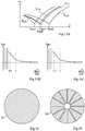
- the extent of the linearity range of an inductive sensor depends on the target-transducer distance d, sometimes called the gap, that is to say the distance between the average plane of the secondary windings of the transducer, and the conductive patterns of the target.
- the target-transducer distance d is defined as the distance between the mean plane of the secondary winding (s) of the transducer and the surface of the conductive patterns of the target facing the transducer.
- the curve V1 represents the evolution of the amplitude V for a target-transducer distance d1
- the curve V2 represents the evolution of the amplitude V for a target-transducer distance d2 less than d1
- the curve V3 represents the evolution of the amplitude V for a target-transducer distance d3 lower d2.
- the line Vl1 in dotted lines, represents the linear approximation of the amplitude V1
- the line Vl2, in dashed line represents the linear approximation of the amplitude V2
- the line Vl3, in dashed lines represents the linear approximation of the amplitude V3.
- the signal V has, at the distance d3, a maximum amplitude greater than the maximum amplitude obtained at the distances d2 and d1.
- the linearity error E L2 of the amplitude V, at the distance d2 is smaller than the linearity errors E L1 and E L3 of the amplitude V at the distances d1 and d3 respectively.
- the linearity error E L corresponds, in a given range of angular positions ⁇ extending for example over half of the electric period of the sensor (on a monotonic portion of the EMF), to the maximum difference ( in absolute value) between a linear approximation of the sensor response and the actual measured response.
- an inductive displacement sensor is provided in which the target-transducer distance d is between 0.8 and 1.5 times the distance d opt for which the linearity error of the amplitude measured by the sensor is minimal. It should be noted that this optimum distance can easily be determined by tests, for example by drawing curves of the type represented in FIG. figure 11 .
- the inventors have, however, found that, in practice, for certain sensors, and in particular sensors having a number N of large pairs of poles, typically greater than or equal to three and even more particularly for N greater than or equal to six, the optimal target-transducer distance in terms of linearity can be relatively small, for example less than 0.2 mm, this can be problematic for certain types of measurement, especially in industrial environments in which such distances are difficult to accept, especially because of tolerances of manufacture, assembly and use.
- the optimal target-transducer distance in terms of linearity is a function of several other parameters, including geometric parameters of the sensor such as the outside diameter of the transducer and / or the target. More particularly, the inventors have found that as the diameter of the sensors increases, the target-transducer distance optimal in terms of linearity increases and can take a relatively large value, for example greater than 1 mm, which can be problematic for certain types of sensors. measurement, especially in industrial environments in which it is desired to ensure a certain compactness.
- the optimal target-transducer distance in terms of linearity is incompatible (too much or too little) with the measurement environment, it can be expected to be at a target-transducer distance as close as possible to the optimal distance. within the constraints of the environment, and to correct the non-linearity by applying a mathematical processing (post-processing) of the measurement signal.
- post-processing a mathematical processing of the measurement signal.
- the inventors have, however, found that in practice this solution has limitations in terms of accuracy and robustness, and is not particularly satisfactory for the implementation of the signal processing methods described in the patents. FR2914126 and FR2891362 .
- a first solution proposed by the inventors and illustrated by the Figures 12A-12D , 13A to 13C, 14 and 15 is adding to the sensor an additional piece of electromagnetic field confinement, placed at a particular distance from the primary winding of the transducer, chosen so as to significantly increase the optimal target-transducer distance in terms of linearity.
- FIGS. 12A-12D are cross-sectional views schematically illustrating four exemplary embodiments of an inductive displacement sensor.
- the senor comprises a transducer 201 and a target 203, arranged at a target-transducer distance d (d being in this example the distance between the mean plane of the secondary winding (s) of the transducer and the plane of the surface of the conductive patterns of the target facing the transducer), and does not include any additional piece of field confinement.
- the senor comprises a transducer 201 and a target 203, arranged at a target distance-transducer d, and further comprises an additional piece 205 of field confinement in a conductive material, for example made of the same material as the conductive patterns of the target, or in any other conductive material, magnetic or not, such as iron, steel, aluminum, copper, etc.
- the piece 205 is disposed on the opposite side of the target 203 to the transducer 201 (i.e., the target 203 is located between the transducer 201 and the workpiece 205), the surface of the workpiece 205 facing the target 203 preferably being approximately parallel to the average plane of the transducer, and therefore also approximately parallel to the average plane of the target (with inaccuracies of assembly close).
- the field confinement piece 205 is preferably periodic in a direction parallel to the degree of freedom in displacement of the sensor, that is periodic by revolution (about an axis which is approximately the axis of symmetry of the target).
- the spatial period of the conductive patterns of the piece of confinement preferably being distinct from that of the conductive patterns of the target.
- the part 205 is symmetrical by revolution.
- the workpiece 205 is disposed at a transducer-part distance, defined in this example as the distance between the mean plane of the primary winding (s) of the transducer, and the plane of the surface of the conductive pattern (s) of the workpiece facing the transducer.
- the part 205 is preferably secured to the target, that is to say mobile with respect to the transducer when the position of the target relative to the transducer changes.
- the sensor comprises a transducer 201 and a target 203, arranged at a target-transducer distance d, and further comprises an additional piece 205 'of field confinement, for example identical or similar to the piece 205 of the figure 12B .
- the piece 205 ' is preferably periodic by revolution, and for example symmetrical by revolution, around an axis of symmetry which is approximately the axis of symmetry of the primary winding of the transducer.
- the workpiece 205 ' is placed on the side of the transducer 201 opposite the target 203 (i.e., the transducer 201 is located between the target 203 and the workpiece 205').
- the piece 205 ' is arranged at a distance between the transducer and the part.
- the distance is defined as being the distance between the mean plane of the primary winding or windings of the transducer, and the plane of the surface of the conductive pattern or patterns of the part facing the transducer.
- the piece 205 ' is preferably integral with the transducer, that is to say fixed relative to the transducer when the position of the target relative to the transducer changes.
- the sensor comprises a transducer 201 and a target 203 disposed at a target-transducer distance d, a first field confinement part 205 (for example identical or similar to the piece 205 of the figure 12B ) disposed on the side of the transducer 201 opposite the target 203, at a distance 1 of the transducer, and a second field confinement piece 205 '(for example identical or similar to the piece 205' of the figure 12C ), disposed on the side of the target 203 opposite the transducer 201, at a distance from the transducer (i.e., the transducer 201 and the target 203 are located between the pieces 205 and 205 ').
- a first field confinement part 205 for example identical or similar to the piece 205 of the figure 12B
- a second field confinement piece 205 ' for example identical or similar to the piece 205' of the figure 12C
- the parts 205 and / or 205 ' may be electrically connected or not, punctually or in a spatially distributed manner, to other elements of the sensor.
- the piece 205 may be electrically connected to one or more conductive patterns of the target, and the piece 205 'may be electrically connected to an electric potential available on the transducer, for example at a point of a secondary winding, a point of the primary winding, or to the electrical ground of the transducer.
- the figure 13A is a diagram comprising four curves E LA , E LB , E LC and E LD respectively representing, for the four examples of the sensor of Figures 12A-12D , the evolution of the linearity error E L of the sensor as a function of the target-transducer distance.
- Each of the curves E LA , E LB , E LC and E LD is of the same type as the curve of the figure 11 that is, it passes through a minimum value of linearity error for a certain optimal target-transducer distance, respectively d optA , d optB , d optC and d optD .
- the distance of optA is less than the distance of optB which is itself smaller than the distance d optC which is itself smaller than the distance d optD .
- the tests carried out by the inventors have shown that the addition of one or more additional pieces of field confinement can increase from several tenths of millimeters to several millimeters the optimal target-transducer distance in terms of the linearity of an inductive displacement sensor. .
- the optimal target-transducer distance in terms of linearity that results from the addition of this or these pieces.
- the optimal target distance-transducer d opt is increased to reach a value between 0.65 and 1.25 times the distance d at which it is desired to operate the sensor, this desired value being for example but not limited to between 0.5 and 1.5 mm which is a range of values compatible with various industrial applications.
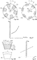
- the Figure 13B is a diagram showing the evolution, for an inductive angular displacement sensor of the type described above, of the optimal target-transducer distance d opt in terms of linearity, as a function of the ratio of the piece-primary distance of pipr ' on the target-primary distance dcpr , in the case of the addition of the additional piece 205 'of field confinement as shown on the Figure 12C or 12D .
- the optimum transducer distance target in terms of linearity is particularly important that the report PIPR '/ d cpr is low.
- the figure 13C is a diagram showing the evolution, for an inductive angular displacement sensor of the type described above, of the optimal target-transducer distance d opt in terms of linearity, as a function of the ratio of the pipr target-primary distance dcpr , in the case of the addition of the additional field containment room 205 as shown on the Figure 12B or 12D .
- the optimum transducer distance target in terms of linearity is particularly important that the report PIPR '/ d cpr is low.
- the target-transducer distance optimal d opt is even more important that the ratio l / d (respectively l / d) is low.
- the ratio of PIPR / d cpr and / or report PIPR '/ d cpr can be chosen such that the distance d opt is compatible with the constraints of the application, for example be greater or equal to 0.3 mm, for example between 0.3 and 10 mm, and preferably between 0.5 and 1.5 mm, in particular for a sensor comprising a number N of large pole pairs, for example N ⁇ 4 and preferably N ⁇ 6.
- the aforementioned choice of distance between the field confinement piece and the transducer is generally not optimal in terms of the signal level provided by the secondary winding (s) of the transducer. Indeed, at this distance, the conductive part 205/205 'causes a significant decrease in the level of the signals V and V' provided by the transducer. It will be noted in particular that in the state of the art of the inductive measurement of angular displacement, it is agreed to remove as far as possible the conductive parts likely to modify the spatial distribution of the electromagnetic field which is established in the presence of the only elements primary, secondary and target.
- This dimensioning criterion applies in particular in the case of electrostatic screens (or shielding screens), which, when provided, are arranged at distances along the Z axis much greater than the distances provided in the described embodiments, so as not to too much attenuate the level of useful signal measured at the secondary level.
- FIGS. 14 and 15 are front views showing examples of field containment pieces 205 that may be used in an inductive displacement sensor of the type described above (parts 205 'of the aforementioned sensors may have similar or identical configurations).
- the piece 205 is a simple disk made of a conductive material (for example metal) of diameter, for example greater than or equal to the outside diameter of the target.
- the disc can be drilled at its center, for example a hole less than or equal to the inner diameter of the conductive patterns of the target.
- the piece 205 is a disc of the same diameter but having radial grooves or slots consistent with the patterns of the target, to obtain a Moiré type constructive effect with the target capable of amplifying the influence of the piece 205 on the distribution of the field at a secondary winding of the transducer.
- the described embodiments are however not limited to these two particular examples.
- the Figures 16A and 16B illustrate two embodiments of an inductive angular position sensor.
- the target of the sensor On the Figures 16A and 16B only the target of the sensor has been shown.
- the arrangement of the transducer, and in particular of its primary winding and its secondary winding (s), is in correspondence with the arrangement of the target, and can easily be deduced from the shape of the target on reading the above.
- the sensor target of the figure 16A is similar or identical to the target of the figure 3B .
- the target of the sensor of the figure 16B also comprises N conductor patterns 137 i shaped annular annular band sector of angular aperture approximately equal to half an electrical period (for example 360 ° / 2N), the N patterns 137 i being evenly distributed along an annular band described by the target.
- the target of the figure 16B differs from the target of the figure 16A in that the conductive patterns 137i have different radial dimensions (lower in the example shown) of the radial dimensions of the conductive patterns 117 i of the target of the figure 16A .
- the annular band determining the shape of the conductive patterns 137i has an outer radius R ext substantially identical to that of the annular band determining the shape of the patterns 117 i , but has an internal radius R int lower than that of the annular band of the conductive patterns 117 i .
- the optimal target-transducer distance d opt in terms of the linearity of the sensor response varies according to the ratio R int / R ext between the inner radius and the outer radius of the annular band in which are located the conductive patterns of the target, and consequently in which are located the turns of the secondary windings of the sensor.
- the figure 17 is a diagram showing the evolution, for an inductive angular displacement sensor of the type described above, of the optimum d opt -transducer target distance in terms of linearity, as a function of the ratio R int / R ext . As it appears on the figure 17 , the optimal target-transducer distance in terms of linearity is even more important that the ratio R int / R ext is important.
- the ratio R int / R ext can be chosen such that the distance d opt is compatible with the constraints of the application, for example, greater than or equal to 0.3 mm, for example included between 0.3 and 10 mm, and preferably between 0.5 and 1.5 mm, especially for a sensor having a number N of large pole pairs, for example N ⁇ 4 and preferably N ⁇ 6.
- the portion of the annular band which constitutes a conductive pattern crushes in the radial direction, resulting in a reduction of the contribution of the radial edges to the global field distribution measured by the secondary, resulting in the signal at the secondary output by an increase in the target distance-optimal transducer in terms of linearity.
- the solution described therefore consists in modifying the spatial distribution of the electromagnetic field, and more particularly the ratio of the radial contributions with respect to the contributions orthoradial, in order to adjust the optimal target-transducer distance in terms of linearity opt to be compatible with the constraints of the application.
- the inner and outer radii of the associated transducer preferably evolve substantially in the same proportions, in order to maximize the level of signal received by the secondary.
- maximizing the signal level at the secondary output more specifically is meant the maximization of the slope at the origin of the signal rather than the maximization of the values taken by the extrema of the signal for certain positions.
- the signal received by the secondary of the associated transducer is maximum when the annular band delimiting the patterns of the target and the annular band delimiting the patterns of the secondary overlap substantially, or otherwise presented, when the orthoradial outer and respectively internal edges of the target and the outer and respectively inner orthoradial branches of the secondary are superimposed.
- the internal diameter and the external diameter of the annular band in which are located the conductive patterns of the target, and consequently in which are located the turns of the secondary winding or windings of the sensor are dimensioned to occupy the maximum of available surface area in the given space, the space requirement being generally constrained by the internal opening and the outside diameter of the support and / or the housing in which the sensor is integrated, or by the outside diameter of the shaft around which the sensor is installed and by the diameter inside of the interface parts between which the sensor is housed.
- a third solution for modifying the optimal target-transducer distance in terms of linearity, usable in addition or as an alternative to adding an additional piece of field confinement, and / or modifying the ratio R int / R ext , is illustrated by the Figures 18A, 18B and 19 .
- This third solution is in the same logic as the solution just described, in the sense that it consists in modifying the shape factor of the conductive patterns of the target and / or the corresponding secondary winding turns, and especially in modify the ratio between the radial dimension and the ortho-radial dimension of the target patterns and / or secondary winding turns, in order to adapt the optimal target-transducer distance in terms of linearity to the constraints of the application.
- the figure 18A illustrates three exemplary embodiments of an angular position sensor of the type described above.
- the target is obtained by regularly repeating the conductive pattern shown along a circular annular band, the inner and outer radii of the patterns 117 i , 117 i ', and 117 i "are substantially identical, but the patterns 117 i , 117 i ', and 117 i "differ from each other by their angular dimensions, more particularly, in this example, the angular aperture of the pattern 117 i ' is approximately equal to one half electric period (For example 360 ° / 2N), as previously described, the angular aperture of the pattern 117 i "is greater than a half electric period of a value ⁇ 1, for example between
- the secondary arrangement of the transducer is preferably in correspondence with the arrangement of the conductive patterns of the target, that is to say that the angular aperture of the secondary patterns adapted to the patterns 117 i 'of the target is substantially equal to an electric half-period (for example 360 ° / 2N), that the angular aperture of the secondary patterns adapted to the patterns 117 i "of the target is greater than 360 ° / 2N by a value substantially equal to ⁇ 1, and that the angular aperture of the secondary patterns adapted to the target 117 i is less than 360 ° / 2N by a value substantially equal to ⁇ 2
- the angular aperture of the secondary patterns takes a value greater than half-period electric sensor, it can be provided to ensure electrical insulation between the adjacent turns of turns, to change the shape of the tracks in at least one metallization plane, and / or to increase the number of metal planes
- Another embodiment option may be to limit the
- the optimal target-transducer distance d opt in terms of the linearity of the sensor response varies as a function of the angular difference ⁇ between the angular aperture chosen for the target and the secondary patterns, and the nominal angular aperture ⁇ equal to one half electric period of the sensor.
- the figure 19 is a diagram showing the evolution, for a given multipole angular displacement sensor of the type described above and illustrated on the Figures 18A and 18B , the optimal target-transducer distance d opt in terms of linearity, depending on the value ⁇ . As it appears on the figure 19 , the optimal target-transducer distance in terms of linearity is even lower than the value ⁇ is important by negative values, and conversely is even more important than the value ⁇ is important by positive values.
- the angular aperture of the conductive patterns of the target can be modified by a value ⁇ with respect to the nominal value ⁇ (equal to one half electric period, for example 360 ° / 2N) , the value ⁇ being chosen such that the distance d opt is compatible with the constraints of the application, for example greater than or equal to 0.3 mm, for example between 0.3 and 10 mm, and preferably between 0.5 and 1.5 mm, especially for a sensor having a number N of large pole pairs, for example N ⁇ 4 and preferably N ⁇ 6.
- the solutions described above can be adapted to inductive angular displacement transducers whose transducer has an angular aperture of less than 360 °, for example less than 180 ° in order to allow "side" mounting. transducer around a rotating shaft, rather than a "through” mount.
- the angular aperture of the target may have a value of 360 °, independent of the angular aperture of the transducer, or take a value less than 360 °, corresponding for example to the angular displacement range of the application .
- the inventors have furthermore found that, in practice, independently of the problem of linearity, the existing inductive displacement sensors, and in particular the multipole sensors, are sensitive to various disturbances. by coupling effect.
- Such disturbances occur for example on the one hand at the level of the transduction zone, that is to say directly at the secondary level of the transducer, and secondly at the level of the electrical connection zone between the secondary of the transducer and a functional block for conditioning the electronic means.
- These disturbances include the coupling of electromagnetic disturbances from outside the sensor (ie not generated by the primary winding), the direct inductive coupling of the primary winding with the secondary winding.
- inductive displacement sensors including multipole sensors, less sensitive to parasitic disturbances and / or less subject to parasitic couplings than existing sensors.
- the inventors propose a particular arrangement of the secondary winding or windings of the sensor, which will be described below.
- N 6 pairs of poles
- a spatially measurement differential for example as described in relation to the figure 7 .
- FIGS 20A and 20C only one secondary 213 of each sensor has been shown, the realization of the primary winding, of the target, and, optionally, of one or more additional secondary windings spatially offset with respect to the winding 213, being within reach those skilled in the art from the explanations of the present description.
- the secondary sensor of the figure 20A and the secondary of the sensor of the figure 20C are similar or identical to the secondary of the figure 7 , with the difference that the electrical connections between the turns are presented.
- the secondary school figure 20A presents a first method of connecting the turns to each other, according to which the entire angular aperture of the annular band over which the secondary extends, for example in the trigonometric direction in the figure, is first traversed, then a second time traverses the entire annular band, this time in the clockwise direction, in order to bring the end electrical end E2 towards the electrical end E1 of departure, and thus close the measuring circuit.
- the secondary school figure 20C presents a second method of connection of the turns to each other, according to which a first half of the angular opening of the annular band on which the secondary extends, for example in the trigonometric direction in the figure, is then first traversed, then the return path is traversed in the clockwise direction to approach the input end E1, then the other half of the angular opening of the annular band on which the secondary extends is maintained, keeping the direction of rotation time, then we travel the return path in the trigonometric direction to bring the end electrical end E2 towards the electrical end E1 starting, and thus close the measuring circuit as for the secondary of the figure 20A .
- the Figures 20B and 20D are front views schematically representing an exemplary embodiment of a transducer of an inductive linear displacement sensor.
- the sensors of Figures 20B and 20D are sensors in which a target (not shown) having N conductive patterns is adapted to move in translation in a rectilinear direction x relative to the transducer.
- the sensor of the figure 20B is for example the same type as the sensor of the figure 20A , adapted in a linear configuration, which essentially amounts to "unrolling" the circular annular bands of the sensor of the figure 20A and replacing the conductor patterns and turns in the form of annular band sector by conductive patterns and turns of generally rectangular or square shape.
- the sensor of the figure 20D is for example the same type as the sensor of the figure 20C , adapted in a linear configuration.
- a secondary winding 213 of each sensor has been shown, the realization of the target, the primary winding, and, optionally, one or more additional secondary windings spatially offset with respect to the winding 213 being within reach those skilled in the art from the explanations of the present description.
- an example of primary winding obtained when "unwinding" the set of two concentric turns 101a and 101b for example described for the sensor of the Figure 1A for example consists of a single turn for a linear sensor as described on the Figures 20B and 20D possibly consisting of several turns.
- the turn of the primary winding is for example of generally rectangular shape, of dimension along y close to the dimension according to y of the conductive patterns of the target and / or turns of the secondary as described above, and of dimension according to x greater than the dimension according to x of the conductive patterns of the target and / or turns of the secondary, so that the contribution to the global electromagnetic field distribution, created at the level of the oriented primary branches according to y and which are at the two ends along x of the primary, or relatively attenuated in the vicinity of secondary branches oriented along y and which are located at both ends along x of the secondary.
- the extent of the primary x will be greater than the extent of the secondary x, and preferably but not exclusive, greater than at least one half electric period of the sensor , distributed equally (at least a quarter of an electrical period) at each end of the sensor.
- a preferred embodiment of the primary winding of an inductive linear displacement sensor is a coil of generally rectangular shape and of greater extent than the overall extent of the set of secondary, for example but not exclusively, greater than at least half an electric period of the sensor, distributed equally (at least a quarter of an electric period) at each end of the sensor.
- the described embodiments are however not limited to this particular case.
- the secondary winding 213 extends in an area having a dimension D tot parallel to the degree of freedom of the sensor, that is to say, parallel to the direction x of displacement of the target relative to the transducer.
- the winding 213 comprises 2N alternating winding winding loops or turns of turns electrically connected in series between its ends E1 and E2.
- the winding 213 comprises N loops or turns 213 i + having the same first direction of winding, and N loops or turns 213 i- having the same second direction of winding opposite the first direction, each turn 213 i + or 213 i- having a dimension in the x-direction approximately equal to an electric half-period of the sensor (that is to say for example approximately equal to D tot / 2N), and the turns 213 i- and 213 i + being juxtaposed two by two alternately along the dimension zone D tot of the secondary winding.
- the section 213A comprises N U-shaped half-turns whose vertical branches are oriented in opposite directions according to a direction y is approximately normal to the x direction
- the section 213B comprises N half U-shaped turns whose vertical branches are oriented alternately in opposite directions in the y direction.
- Each half turn in U of the section 213A has its vertical branches approximately aligned with the vertical branches of a U-shaped half-turn of opposite orientation of the section 213B.
- the sections 213C and 213D are arranged in a similar arrangement in the right part of the winding.
- the portions of the winding 213 orthogonal to the direction of displacement x are traversed twice and twice only by the wire or the winding track (with the exception of the two extreme orthogonal portions of the winding located at both ends of the distance D tot , which in this example are traversed only once - this exception does not occur, however, in the case of an angular aperture angle sensor of 360 °, in which all radial portions of the winding can be traversed twice and twice only by the winding wire or track), and the portions of the winding 213 parallel to the direction of displacement x are traveled once and only once by the wire or the winding track.
- the implementation of the solution of the figure 20D is consistent with the implementation of a solution of the type described in relation to the figure 20B , and by linear-angular transposition is also consistent with the implementation of the solutions of the Figures 20A and 20C .
- the sequence according to which this path is traversed differs between the transducer of the figure 20D (and by transposition the transducer of the figure 20C ), and the transducer of the figure 20B (and by transposition the transducer of the figure 20A ).
- the arrangement described in relation to the Figures 20D and 20A is designed to reveal an intermediate connection point M between the ends E1 and E2.
- the winding 213 may be provided, in addition to terminals PE1 and PE2 connecting at its ends E1 and E2, a third access terminal PM connected to the midpoint M of the winding.
- the secondary winding has as many turns 213 i + (so-called positive) on the right than turns 213 i + on the left (N / 2 on each side), and consequently the secondary winding has as many turns 213 i- (say negative) on the right as turns 213 i- left (N / 2 on each side).
- the inventors have found that when the sensor is produced according to the second embodiment, if reference is made to the midpoint M of the winding at a given electrical potential of differential measuring means, for example at a constant potential and centered on the measuring voltage dynamic of the measuring means, the common-mode component contained in the electrical signal present at the terminals of the dipole E1-E2, which carries no useful information on the position and displacement of the target with respect to the transducer, is small compared to the differential mode component contained in the same electrical signal present at the terminals of the dipole E1-E2, the differential mode component being on the contrary carrying useful information on the displacement of the target relative to the transducer.
- the arrangement of the sensor Figures 20C and 20D making it possible to place the midpoint M in the immediate vicinity of the ends E1 and E2 thus has a certain advantage, for example with respect to the arrangement of the sensor of the figure 20B in which the mid-point M is remote from the ends E1 and E2, and more generally with respect to the arrangements of the sensors of the Figures 20A and 20B wherein the voltages E1-M and E2-M depend on the position of the target with respect to the transducer, or said otherwise, with respect to the sensor arrangements in which the ratio of the common mode component to the differential mode component to the The terminals of a secondary winding are not weak and vary greatly with the position of the target relative to the transducer.
- an advantage of the sensors described in Figures 20C and 20D when the mid point M is connected in a manner adapted to the measuring means lies in the high immunity of the two electrical potentials at the ends E1 and E2, to the component of the electromagnetic excitation field (primary) which does not vary with the position, whereas the only spatially differential character of the sensor measurement of the figure 7 guarantees immunity only on the difference of the potentials at the E1 and E2 ends.
- the sensors of the Figures 20C and 20D also offer increased immunity to electromagnetic and / or electrostatic disturbances emitted by an external source at the transduction zone and whose spatial distribution is relatively homogeneous, or more generally an increased immunity to any form of electromagnetic and / or electrostatic disturbance by compared to sensors such as those described in Figures 20A and 20B .
- Examples of practical advantages of increased immunity to external disturbances in the transduction zone are, for example, the reduction of the stresses on the protections of the electronic measuring means, such as overvoltage protections, and / or the relaxation of design constraints on electrical signal conditioning systems, such as the common mode rejection ratio of differential amplifiers.
- the adaptation of an inductive sensor to implement a midpoint according to the second embodiment can lead to increase the number of interfaces of the conditioning circuit (for example the number of legs of an integrated circuit) .
- the number of interfaces of the conditioning circuit for example the number of legs of an integrated circuit.
- the figure 20E is an electrical representation "small signals" useful induction phenomena V M1 and V M2 , that is to say signals carrying information or part of the information on the position and / or the displacement of the target relative to the transducer, and parasitic induction phenomena Vp, Vp ', and Vp''at the connection wires between the terminals E1, E2 and M of the transducer, and the terminals PE1, PE2 and PM for example connected to the level of external electrical means.
- the common-mode disturbances Vp, Vp ', and Vp'' are substantially equal and substantially compensate in the measurements V PE1 (realized at the terminals of the PM-PE1 dipole) and V PE2 (made at the terminals of the PM-PE2 dipole) on the one hand, and in the V PE1PE2 measurement carried out across the PE1-PE2 dipole, on the other hand.
- the signals measured at the terminals of the tripole become extremely immune to external electromagnetic disturbances in the connection zone between the transducer terminals (E1, E2, M) and the connection terminals to the external electrical means (PE1, PE2 , PM), on the one hand to the first order by limiting the risks of overvoltage on the inputs of the electronic means (the signal levels remain in the dynamics of the means of conditioning, and the measurement is valid unconditionally), and secondly second order by relaxing the requirements on the common mode rejection ratio of the differential measurement V PE1PE2 (the measurement error introduced by the disturbances is small).
- the terminal PM a reference voltage of the conditioning unit, or half of the supply dynamics of the conditioning unit, or even the electronic mass, without these embodiments being exclusive of other embodiments such as for example the connection of the terminal PM or M directly to a potential of the transducer such as the mass.
- the different windings can be arranged in and / or on different superimposed support layers each comprising one or several levels of metallization.
- This configuration although satisfactory for many applications, can however pose problems of robustness and accuracy. Indeed, it follows that the average planes of the different secondary windings are located at slightly different distances from the primary winding and the target. This results, in particular, in the first order, a difference in transduction gain, and therefore a difference in signal level at the output of the different secondary windings, and the second order of the different linearity characteristics between several secondary windings of the same transducer.
- the metallization plane changing zones are located such that there is a symmetry and / or antisymmetry relationship between most of the track portions disposed on the first metallization level, and most of the track portions disposed on the second level of metallization, as illustrated in FIGS. Figures 21A, 21B , 22A and 22B .
- the average planes of the different secondary windings are merged and correspond to a plane virtual intermediate located between the first and second metallization levels. This confers on each electromotive force induced at the terminals of each secondary, a response as a function of the position of the target substantially identical in terms of amplitude and linearity, to that of the electromotive forces induced across the other secondary.
- the angular aperture of the target may alternatively maintain a value of 360 ° independently of the angular aperture taken by the secondary or secondary transducer, or take a value less than 360 ° and for example adapted to the angular displacement range of the application.
- FIGS. 21A and 21B are front views schematically showing an exemplary embodiment of a transducer with two secondary windings 223 (in outline) and 223 '(solid line) spatially offset by a quarter of the electric period of the sensor, for a inductive sensor of angular displacement.
- the described embodiments are however not limited to this particular case.
- the track length formed in the level M1 is approximately equal to the track length formed in level M2.
- the figure 21A is a front view of the level of metallization M1
- the figure 21B is a front view of the metallization level M2.
- the patterns of the level M1 are found substantially from the units of the level M2 by antisymmetry with respect to an intermediate plane between the mean planes of the levels M1 and M2.
- the windings 223 and 223 'each have, seen from above, an arrangement of the type described in connection with the figure 20C (ie an arrangement of the type described in relation to the figure 20D adapted in an angular configuration, the winding principle described in relation to the figure 20D then applying in a similar way, the distance D tot not being a linear distance but being now an angular distance, equal to 360 °).
- the portions of the winding 223 orthogonal to the direction of movement of the target relative to the sensor, that is to say the radial branches of the winding are scanned twice and only twice by the wire or the winding track, and the portions of the winding 223 parallel to the direction of movement of the target with respect to the sensor, that is to say the ortho-radial branches of the winding, are traversed once and once only by the wire or the winding track.
- the radial portions positioned at angles offset by 0 ° modulo an electric half-period, with respect to the angle which characterizes the end E1, are traversed twice and twice only by the wire or the winding track 223;
- the radial portions positioned at angles offset by a quarter of an electric period modulo an electric half-period, with respect to the angle which characterizes the end E1, are traversed twice and twice only by the wire or the winding track 223 ';
- the ortho-radial portions are traversed once and once only by the wire or the track of the winding 223, and once and once only by the wire or the track of the winding 223 '.
- This embodiment makes it possible to contain on two planes and only two metallization planes, two secondary ones as described in the previous solutions, that is to say without making any concessions on the overall shape of the patterns of each secondary. It should be noted that the embodiments presented on the Figures 21A, 21B , 22A and 22B implement two secondary disposed on two metallization planes, but are not exclusive of other embodiments such as an embodiment that would implement for example three secondary disposed on three metallization planes.
- each of the half-turns U of each of the sections 223A, 223B, 223C and 223D of the winding 223 has approximately half of its length in the level of metallization M1 and the other half of its length in the level of metallization M2.
- a change of level occurs every L / 2 meters of conductive track approximately, where L designates the length of a turn of the winding, constituted by the series series of two half-complementary U-turns.
- the level change points of the winding are located in the middle of the orthoradial branches (or horizontal branches) U forming the half-turns.
- the described embodiments are however not limited to this particular case.
- the numbers ranging from c1 to c28 designate, in the order of travel between the terminals E1 and E2, different portions of the winding 223.
- the secondary winding 223 '(solid line) is disposed in the levels M1 and M2 in an arrangement substantially identical to that of the winding 223, but with an angular offset of approximately a quarter period electrical (i.e. 15 ° in this example) with respect to winding 223.
- connection tracks at the ends E1 and E2 of the winding 223 may for example be located respectively in the metallization levels M1 and M2, and be superimposed on each other. This makes it possible to minimize the parasitic coupling difference on each of these branches with any external induction source (primary connection track, external electromagnetic disturbance, etc.).
- An access track at the midpoint M of the winding may be located in a third metallization level (not shown) superimposed on the access tracks to the terminals E1 and E2 which are in the metallization levels M1 and / or M2, or be located in one of the metallization levels M1 and M2, slightly offset with respect to the access tracks to terminals E1 and E2.
- a similar arrangement of the access tracks to the corresponding terminals E1 ', E2' and M 'of the winding can be provided for the winding 223'. More generally, whatever the arrangement of the access tracks, in order to increase the immunity to electromagnetic disturbances between the (secondary) transduction zone and the access and / or connection terminals of the signal conditioning means, it is preferable to keep the paths from the ends E1 and E2 as close as possible (for example superimposed in the PCB technology), and to a lesser extent to place the path from the intermediate point M close enough paths from the ends E1 and E2.
- the vias performing the metallization level changes have small dimensions relative to the skin thickness, the working frequency, the material that constitutes them, it can be expected not to add the conductive pads and particular not to proceed with their drilling, which can reduce the cost of the device.
- FIGS. 22A and 22B are front views schematically showing an alternative embodiment of a transducer of the type described in connection with the Figures 21A and 21B .
- This variant embodiment differs from the example of Figures 21A and 21B by the fact that, in the example of Figures 22A and 22B , the metallization level changes are more numerous than in the example of Figures 21A and 21B . So, in the example of Figures 22A and 22B instead of a change in metallization level every L / 2 meters of conductive track of the secondary winding, where L is the length of a turn of the winding, it is expected to make k changes metallization level every L / 2 meters of track, with k integer greater than or equal to 2.
- the number k can be chosen taking into account the internal and external radii of the transducer.
- k can be chosen as large as it is possible to place adjacent vias (for example equi distributed) on the orthoradial portions without these vias short circuit.
- the variant of Figures 22A and 22B however, is compatible with sensors having a larger number of pole pairs.
- conductive filler patterns without electrical connection function may be provided to further symmetrize the structure.
- the maximum range of the range of positions that can be detected by the sensor is about one half electric period (for example D tot / 2N ie 360 ° / 2N in the case of an angular sensor ) if the sensor has only one secondary winding, and can rise to approximately one electrical period (for example D tot / N ie 360 ° / N in the case of an angular sensor) if the sensor has more than one secondary winding, for example if it comprises two identical secondary windings spatially offset by a quarter of an electric period (for example D tot / 4N, that is to say 360 ° / 4N in the case of an angular sensor), or if it comprises three windings identical termals spatially shifted one-sixth of an electric period (for example D to
- the multipole angular displacement sensors of the type described above do not make it possible to carry out displacement measurements over a complete revolution (360 °) in an absolute manner, that is to say without use methods for memorizing the history of movements, and / or methods of referencing the position at startup and / or during the operation of the sensor.
- This observation is true regardless of the number N of pairs of poles greater than or equal to 2, and can be even more problematic when the number N is high, for example N ⁇ 4 and preferably N ⁇ 6.
- the linear displacement inductive sensors described above have the same limitations and do not make it possible to measure the full extent of D tot absolutely.
- an inductive displacement sensor such that, for a given number N of pairs of poles, for a given dimension D tot of the secondary winding (s) of the transducer, parallel to the degree of freedom of the sensor, the sensor is adapted to detect the position of the target relative to the transducer substantially over the full extent D tot of the transducer.
- an angular position sensor it is sought to provide a sensor adapted to detect the position of the target relative to the transducer over a complete revolution, that is to say over an angular range of approximately 360 °, even when the number N of pairs of poles of the sensor is large, for example N ⁇ 4 and preferably N ⁇ 6.
- the figure 23 is a front view schematically showing an example of an inductive multi-pole angular displacement sensor. On the figure 23 only the target of the sensor has been shown.
- the target of the sensor of the figure 23 further comprises N + 1 conductive patterns 119 j , with j integer ranging from 1 to N + 1, regularly distributed along the 360 ° of a second circular annular band 120 of the target, concentric with the first band 118 and not superimposed at the first band 118.
- the second annular band has an inner radius greater than the outer radius of the first annular band.
- the second electric period secondary winding D tot / N is substantially identical to the first winding and spatially shifted by a quarter of an electric period (D tot / 4N) with respect to the first winding
- the fourth electric period secondary winding D tot / (N + 1) is substantially identical to the third winding and spatially shifted by a quarter electric period (D tot / 4 (N + 1)) relative to at the third winding.
- the transducer may comprise, in the first annular band, a plurality of secondary windings of electric period D tot / N, substantially identical to the first winding and spatially offset relative to each other by a certain percentage of electrical period. and, in the second annular band, a plurality of secondary windings of electric period D tot / (N + 1) substantially identical to the third winding and spatially offset from each other by a certain percentage of electric period.
- the transducer of the sensor comprises, in the first annular band of the transducer, a first pair of identical secondary windings period electrical 360 ° / 2N, spatially shifted by a quarter electric period, and, in the second annular band of the transducer, a second pair of identical secondary windings of electric period 360 ° / 2 (N + 1), spatially shifted d a quarter of an electric period.
- this sensor is able to provide two sets of two distinct electromotive forces, from which a position estimate can be constructed respectively over a range of position equal to 360 ° / 2N and over a range of position equal to 360 ° / 2 (N + 1).
- the figure 24 is a diagram representing the evolution, as a function of the position of the target relative to the transducer, of the estimate ⁇ N (in solid line) of the position obtained from the electromotive forces measured at the terminals of the first pair of windings secondary, and estimation ⁇ N + 1 (in broken lines) of the position obtained from the electromotive forces measured at the terminals of the second pair of secondary windings of the transducer.
- one of the position estimation signals for example the signal ⁇ N
- the signal ⁇ N can be used to provide "fine" displacement information of the target in N angular ranges of extents restricted to the 360 ° electric period. / N, and the difference ⁇ N + 1 - ⁇ N between the other position estimation signal (the signal ⁇ N + 1 in this example) and this signal can be used to provide a coarse absolute information of the position of the target on a full turn. Under these conditions, the rough absolute information makes it possible to adapt the fine but angularly limited information, in order to make an estimation of absolute and fine displacement over 360 °.
- An advantage of the sensor of the figure 23 is that it makes it possible to benefit to a certain extent from the advantages of multipole sensors, particularly in terms of robustness to positioning errors, while being adapted to provide measurements over an extended position range with respect to multipole sensors of the type described herein. -before.
- N1 and N2 N1 + 2
- r is an integer less than or equal to N1-1, so that N2 is less than or equal to 2N1-1. If N2 could be equal to 2N1, the difference between the two normalized position estimates, as described above, would provide information close to that provided by the first set of patterns (corresponding to N1), and would not allow better estimate the absolute position by the difference between the two normalized position estimates. Thus, as soon as r is less than or equal to N1-1, the embodiments and advantages of the invention are applicable.
- ra a preferably low value, for example r is equal to 1 as described above and illustrated in FIG. figure 23 .
- the size of the sensor is increased compared to a sensor of the type described above.
- the transducer surface "useful" for making a measurement is that of a circular annular band about twice the width of the "useful" annular band of a transducer of the type described in connection with the figure 3A .
- the "useful" target surface for making a measurement is that of an annular band approximately twice as wide as that of the "useful" annular band of a target of the type described in relation to the figure 3B .
- the realization of the primary is more complex than in the previous embodiments if it is desired to excite in a relatively uniform manner each of the annular bands of scale N and N + 1 of the sensor. In practice, it may be necessary to use three separate sets of turns to achieve the primary excitation winding.
- the figure 25 is a front view schematically showing an example of an embodiment of an inductive displacement sensor.
- the sensor of the figure 25 is a multi-pole sensor with two scales of N and N + 1 measurements, operating according to the principle of a vernier as described in connection with the Figures 23 and 24 . On the figure 25 only the target of the sensor has been shown.
- the target of the sensor of the figure 25 comprises a plurality of disjoint conductive patterns 127i distributed along the 360 ° of a circular annular band 130 of the target. As it appears on the figure 25 the set of patterns formed by the conductive patterns 127 i is non-periodic.
- the various conductive patterns 127 i have the shape of angular sectors, of different angular openings, of the annular band 130 of the target, and are a priori irregularly distributed along the annular band 130.
- the set of patterns formed by the conductive patterns 127 i on the annular band 130 of the target corresponds to the (virtual) superposition of first and second sets of periodic conducting patterns of respective periodicities 360 ° / N and 360 ° / (N + 1 ).
- the first set of patterns comprises N elementary patterns 129j (in solid lines) regularly distributed on the along the annular band 130 of the target, each elementary pattern 129j having the shape of a sector of the annular band 130, of angular aperture approximately equal to 360 ° / 2N.
- the second set of patterns comprises N + 1 elementary patterns 131 k (in broken lines) regularly distributed along the annular band 130, each elementary pattern 131 k having the shape of a sector of the annular band 130, opening angle approximately 360 ° / 2 (N + 1).
- the conductive pattern surfaces of the target of the figure 25 correspond to the cumulation or union of the surfaces of the conductive patterns of a first target of the type described in relation to the figure 3B , of electric period 360 / N, and a second similar target, having the same internal and external radii as the first target, but having an electric period 360 ° / (N + 1).
- the inventors have found that although the conductive patterns of electric period 360 ° / N and 360 ° / (N + 1) of the target overlap and short circuit, and therefore the target comprises conductive patterns 127 i unevenly distributed over a full 360 ° turn, these patterns having residual angular apertures that may be different from the periodic angular openings of the patterns of the games.
- secondary windings of the transducer, the sensor of the figure 25 allows performing, with very good performance, displacement measurements over the entire distance D tot (that is to say, over a complete revolution) by a similar or identical vernier type reading method to the method described in relation to the Figures 23 and 24 .
- An advantage of the sensor of the figure 25 is that, due to the superposition of the respective electric period patterns 360 ° / N and 360 ° / (N + 1), the size of the sensor can be reduced compared to a configuration of the type described in relation to the figure 23 .
- a single primary winding for example of the type described in connection with the figure 3A , enough to generate a sufficiently uniform magnetic excitation for a good functioning of the sensor.
- the figure 26 is a front view schematically showing an embodiment variant of the sensor of the figure 25 . On the figure 26 only the target of the sensor has been shown.
- the target of the sensor of the figure 26 comprises a plurality of disjoint conductive patterns 137 i distributed along the 360 ° of a first circular annular band 138 or wide band of the target.
- the set of patterns formed by the patterns 137 i on the annular band 138 of the target corresponds to the superimposition of first and second sets of periodic patterns of respective electrical periods 360 ° / N and 360 ° / (N + 1).
- the first set of patterns comprises N elementary conductive patterns 139j (in solid lines) regularly distributed along the first annular band 138 of the target, each elementary pattern 139j having the shape of an angular sector of the first band annular 138 of the target, angular aperture approximately equal to a half electric period 360 ° / 2N.
- the second set of patterns comprises N + 1 elementary patterns 141 k (in broken lines), evenly distributed along a second circular annular band 142 or narrow band of the target, concentric with the annular band 138 and included in the annular band 138, ie having an inner radius greater than the inner radius of the first annular band, and / or an outer radius less than the outer radius of the annular band 138.
- Each elementary pattern 141 k has the shape of an angular sector the annular band 142 of the target, with an angular aperture approximately equal to 360 ° / 2 (N + 1).
- the width (radial dimension) of the second annular band 142 of the target is preferably substantially less than the width (radial) of the first annular band 138 of the target, for example two to twenty times smaller than the width of the first annular band (the wide band).
- the secondary winding (s) carrying out the "fine" measurement as described above are the windings whose turns have the shape of angular sectors of the widest annular band of the transducer (substantially identical to the annular band 138 of the target) . It is understood by the notion of fine measurement that priority is given to design efforts to ensure the performance and robustness of the measurement by broadband subscribers, possibly and to some extent depends on the performance and the robustness of the measurement carried out by the secondary of the narrow band.
- An additional advantage of the sensor of the figure 26 compared to the sensor of the figure 25 is that it is more robust to positioning errors between the target and the transducer than the sensor of the figure 25 .
- the measurement obtained across the secondary windings of the wide band (preferably associated with the fine measurement) is more robust to the positioning errors between the target and the transducer than in the sensor of the figure 25 .
- reducing the area of one of the measuring scales relative to the other reduces to a certain extent the coupling created by the patterns of the narrow band on the patterns of the broadband at the level of the target, particularly in relation to the target of the figure 25 for which the reciprocal influence of one set of patterns on the other is substantially equivalent and very strong. It is thus possible to increase the robustness of one of the sets of secondary to positioning errors.
- the average radius of the second circular annular band of the sensor (the narrow band) is approximately equal to the average radius of the first circular annular band of the target (the wide band).
- This configuration is advantageous because it allows substantially equivalent distance away from the effects of the inner and outer orthordial portions of the conductive patterns.
- the described embodiments are however not limited to this particular configuration.
- the Figures 27A to 27C are front views schematically showing another embodiment of the sensor of the figure 25 .
- the Figure 27A is a front view of the target
- the Figure 27B is a front view of a part of the transducer
- the figure 27C is a front view of another part of the transducer.
- the two parts of the transducer represented separately on the Figures 27B and 27C for the purposes of illustration are found integral and superimposed concentrically in a single transducer, without the decomposition of the constituent elements of said transducer in these two figures does not presage a particular distribution on several levels of metallization.
- the target of the sensor Figures 27A to 27C comprises a plurality of disjoint conductive patterns 147 i distributed along the 360 ° of a first circular annular band 148 or wide band of the target.
- the set of patterns formed by the conductive patterns 147 i on the first annular band 148 corresponds to the superimposition of a first set of periodic patterns of electric period 360 ° / N, and second and third sets of periodic patterns of electrical periods 360 ° / (N + 1).
- the first set of patterns comprises N conducting patterns 149j (in solid lines) regularly distributed along the annular band 148 of the target (wide band), each elemental pattern 149j having the shape of a sector of the band 148, with an angular aperture approximately equal to 360 ° / 2N.
- the second set of patterns comprises N + 1 elementary conductor patterns 151 k (in broken lines) regularly distributed along a second annular band 152 of the target (narrow band), concentric with the first annular band 148 and included in FIG. strip 148, ie having an inner radius greater than the inner radius of the annular band 148, and an outer radius smaller than the outer radius of the annular band 148.
- the inner radius of the annular band 152 of the target is greater than the average radius of the first annular band 148.
- This embodiment is in no way limiting, and in particular the narrow strips 152 and 154 may be arranged differently in the wide band 148, without the average radius of the band wide 148 does not constitute an impenetrable limit for one or other of the narrow bands.
- Each elemental pattern 151 k has the shape of a sector of the second annular band 152 of the target, with an angular aperture approximately equal to 360 ° / 2 (N + 1).
- the (radial) width of the annular band 152 of the target is preferably small relative to the width of the annular band 148 of the target, for example from three to twenty times smaller than the width of the first band.
- the third set of patterns comprises N + 1 elementary conductor patterns 153 k (in broken lines), regularly distributed along a third annular band 154 of the target (narrow band), concentric with the annular band 148 and included in the band In this example, the outer radius of the annular band 154 of the target is less than the average radius of the annular band 148.
- the difference between the mean radius of the first annular band 148 and the average radius of the third annular band 154 is for example approximately equal to the difference between the average radius of the second annular band 152 and the average radius of the first annular band 148.
- Each elemental pattern 153 k has the shape of a sector of the third annular band 154 of the target, with an angular aperture approximately equal to 360 ° / 2 (N + 1).
- the width of the third annular band is for example approximately equal to the width of the second annular band.
- the width of the third annular band 154 is such that the area of a pattern of the annular band 154 is approximately equal to the area of a pattern of the annular band 152.
- the periodic patterns of 360 ° / (N + 1) periodicity of the annular band 154 of the target are spatially shifted by 360 ° / 2 (N + 1) relative to the periodic patterns of 360 ° / (N + 1) periodicity of the annular band 152 of the target.
- the "empty" angular aperture ranges 360 ° / (N + 1) separating two adjacent elementary conductor patterns 151 k approximately one elementary pattern 153 k extends
- the "empty" angular ranges of angular aperture 360 ° / (N + 1) between two individual conductive patterns 153 k neighbors extends approximately one elementary conductor pattern 151 k.
- substantially all the radial directions of the target cross an elemental conductive pattern 151 k or an elemental pattern 153 k .
- the third and fifth secondary windings are of opposite polarities, that is to say they are spatially shifted by 360 ° / 2 (N + 1) according to the polarity convention (represented by a + or - sign) established on the figure 7 and recovery in the following description.
- the fourth and sixth secondary windings are arranged relative to one another in an arrangement substantially identical to the arrangement between the third and fifth secondary windings.
- the first and second secondary windings are spatially offset by 360 ° / 2N relative to each other
- the third and fourth secondary windings are spatially offset.
- the fifth and sixth secondary windings are shifted by 360 ° / 2 (N + 1) one compared to each other.
- the transducer may comprise, in the first annular band, a plurality of secondary windings of electric period D tot / N, substantially identical to the first secondary winding and spatially offset relative to each other by a fraction of the electrical period. ; in the second annular band, a plurality of secondary windings of electric period D tot / (N + 1), substantially identical to the third secondary winding and spatially offset relative to each other by an electric period fraction; and in the third annular band, a plurality of secondary windings of electric period D tot / (N + 1), substantially identical to the fifth secondary winding and spatially offset with respect to each other by an electric period fraction.
- the measurement obtained across the secondary windings 243 of the wide band is more robust to the positioning errors between the target and the transducer than in the sensor of the figure 26 .
- the sensor of Figures 27A to 27C substantially all the radial directions of the target intersect with one and only one elementary conductive pattern of a narrow band disposed on either of the two narrow bands of the target.
- the two narrow bands of the target are preferably disposed sufficiently far from the two inner and outer orthoradial branches of the secondary 243 of the broad band of the transducer.
- the coupling of the conductive patterns of the two narrow bands of the target on the measurement across the secondary 243 of the broadband results from the combination of the induction of the conductive patterns of a narrow band of the target and induction of the conductive patterns of the other narrow band of the target, these two contributions compensating substantially regardless of the position of the target relative to the transducer.
- the parasitic coupling then takes a relatively stable value when the position of the target relative to the transducer changes.
- the coupling takes a substantially zero value when the secondary of the broadband comprise 2N turns of alternating winding direction, as has been described for the sensor of the figure 3 for example, to perform a spatially differential measurement.
- Another formulation is to consider that the secondary broadband transducer "roughly" sees the two narrow bands staggered as a single narrow and substantially full conductive medium band or continuous on D tot from the electromagnetic point of view (and not at the same time). electrical sense), and that this virtual band actually induces at the terminals of said secondary a signal substantially independent of the position.
- the inventors have found that the measurement obtained at the terminals of the secondary winding 253 (of a narrow band) exhibits a behavior as a function of the position of the target relative to the transducer which is similar to the behavior as a function of the position of the measurement obtained at the terminals of the secondary winding 255 (of the other narrow band).
- the inventors have also found that, in the event of defects in the positioning of the target with respect to the transducer, the behavior as a function of the position of the measurement at the terminals of one of the two windings 253 or 255 of one of the two narrow strips , has relatively complementary deformations of the deformations obtained on the measurement at the terminals of the other winding.
- the coupling of the conductor patterns 149j of the wide band of the target to the measurement at the terminals of the composite winding results from the combination of the induction of the conductive patterns 149j on the secondary 253 (a narrow band) and of induction conductors 149 j patterns on the secondary 255 (the other narrowband), these two substantially offsetting whatever the position of the target relative to the transducer.
- the parasitic coupling then takes a relatively stable value when the position of the target relative to the transducer changes.
- the coupling takes a substantially zero value when the secondary 253 and 255 (narrow strips) have 2 (N + 1) turns of alternating winding direction, as has been described for the sensor of the figure 3 for example, to perform a spatially differential measurement.
- Another formulation is to consider that, when the position of the target relative to the transducer changes, the reading made by a secondary of the narrow band of the transducer of the set of conductive patterns associated with it on the target is substantially "in phase” with the reading by the secondary of the other narrow band of the transducer of the set of conductive patterns associated with it on the target. Furthermore, when the position of the target relative to the transducer changes, the reading made by a secondary of the narrow band of the transducer of the set of conductive patterns 149j of the wide band of the target is substantially "in opposition of phase” with the read by the secondary of the other narrow band of the transducer of the same set of conductive patterns of the broad band of the target.
- parasitic coupling takes a substantially zero value when the secondary elements of each narrow band are designed for this purpose, whereas the useful signal is conserved and / or amplified.
- one of the elementary electric period patterns 360 ° / (N + 1) is approximately centered on the same angular position as one of the elementary electric period patterns 360 ° / N.
- the pattern 131 1 is centered on the same angular position as the pattern 129 1
- the pattern 151 1 is centered on the same angular position as the pattern 149 1 .
- This configuration is preferred because it contributes to increasing the overall symmetry level of the sensor, which in particular facilitates the manufacture and visual control of the target, or to facilitate the design and manufacture of sets of secondary windings.
- the described embodiments are however not limited to this particular case.
- the number of pairs of poles is preferably even for the patterns of the wide band, in order to benefit from increased symmetry of the transducer on both sides of the midpoint (in particular when the transducer is made according to the second aspect).
- planar angular displacement sensors do not apply only to planar angular displacement sensors, but can be applied to other types of inductive displacement sensors, and in particular planar linear displacement sensors, or non-planar angular displacement sensors, for example linear displacement sensors "wound” (for example shaped according to a cylinder) around and facing a rotating part on which is fixed a target also of linear type and "wound” (for example shaped according to a cylinder).
- linear displacement sensors "wound” for example shaped according to a cylinder
- the target of an inductive displacement sensor consists of a metal plate cut through its entire thickness in order to keep, opposite the windings of the transducer, only portions of the plate corresponding to the conducting patterns of the target, as represented for example in Figure 50 of the patent EP0182085 above.
- the target may be constituted by a dielectric support, for example a plastic plate, a face facing the transducer is partially coated with a metal layer forming the conductive pattern or patterns of the target.
- Targets of the aforementioned type have points of weakness, which can be problematic in some applications, including applications in which the moving parts which one wishes to be able to detect the displacement are likely to undergo significant shocks or vibrations.
- the inventors have in particular identified the conductive patterns when they are relatively thin and / or angular, and the dielectric support which is generally soft (epoxy PCB, plastic ).
- the achievement of a robust attachment between the target and a moving part which one wishes to be able to detect the displacement can pose difficulties.
- This attachment (for example by gluing, screwing, fitting, etc.) may in particular constitute a point of mechanical weakness.
- Such weak points limit the industrial applications of sensors equipped with such targets, and in particular require either to instrument the rotating mechanical part subsequent to the assembly operations of said part, especially when these assembly operations are performed by means of tools of such as mallets and presses, either to protect the target and / or the transducer in a solid mechanical case.
- This is for example the case of instrumented bearings which are embedded in the means of presses large tonnage.
- a target for an inductive displacement sensor that overcomes all or part of the disadvantages of existing targets, particularly in terms of solidity.
- a target for an inductive displacement sensor formed of a single conductive metal part (for example a piece of steel), or monobloc target, machined so that the face the target intended to be turned towards the transducer comprises one or more metal studs projecting from a metal bottom wall.
- the studs of the target correspond to the conductive pattern or the conductive patterns of the target, and the portions of the bottom wall not surmounted by a stud correspond to zones without a conductive pattern of the target, that is to say usually non-conductive zones in the traditional targets for inductive displacement sensor.
- the figure 28 is a perspective view showing an exemplary embodiment of such a monobloc target 301, for an inductive displacement sensor.
- Each stud 307 i has an apex or an upper face approximately flat and parallel to the wall 309.
- the side walls of the studs are approximately orthogonal to the wall 309.
- the upper faces of the studs 307 i of the target 301 define the conductive patterns of the target.
- the target 301 has a conductive pattern substantially identical to that of the target of the figure 3B , that is to say that, in projection in a direction orthogonal to the mean plane of the disk, the pads 307 i have substantially the same shape and are arranged substantially in the same way as the conductive patterns 117 i of the target of the figure 3B .
- the operating principle of the target 301 is similar to what has been described previously, ie when the target is placed in front of a transducer emitting a magnetic excitation, induction phenomena, for example eddy currents, occur in the pads 307 i , especially at the upper face of the pads, causing a variation of a transducer output signal level depending on the position of the pads 307 i relative to the transducer.
- the portions of the target surface opposite the transducer located between the pads 307 i are conductive. Consequently, under the effect of the magnetic excitation generated by the primary winding, induction phenomena, for example eddy currents, can also occur in these portions of the target, at the level of the bottom wall. 309. More generally, and for example in the case of the sensor of the figure 28 wherein the pads are in uniform electrical contact with the support of the target characterized by the wall 309, the electromagnetic field distribution results from the overall interaction of the conductive structure of the target with the magnetic excitation generated by the primary.
- the induction phenomena occurring in the wall 309 are smaller than the induction phenomena occurring at the surface.
- studs 307 i The tests carried out by the inventors have shown that the inductive contribution of the wall 309 may possibly cause a modification such as attenuation or a modification of the linearity characteristics of the useful output signal of the transducer when the height of the pads 307 i is small, but it does not degrade but not the accuracy of the position measurements that can be made by the sensor.
- the height of the pads can be chosen so that the distance d opt is compatible with the intended application, for example between 0.5 and 1.5 mm, which is a range of values compatible with various industrial applications.
- the height of the pads 307 i is between 0.1 and 30 mm and preferably between 1 and 10 mm.
- any type of target for inductive displacement sensor with one or more conductive patterns can be made in one-piece form, as described in connection with the figure 28 for example inductive linear displacement sensor targets, or planar angular displacement inductive sensor targets having different conductive patterns from that of the figure 28 , ie for example different angular sectors or rectangles, and for example characterized in that at least one of their contours (for example the outer contour) evolves substantially as a spiral depending on the angle on the target, or in that at least one of their contours evolve substantially sinusoidally depending on the angle on the target.
- FIG. figure 29 Another nonlimiting example of a single-piece target 401 for an inductive sensor for planar angular displacement is represented in FIG. figure 29 .
- the target 401 has the general shape of a metal disk, machined such that a face of the disk intended to be turned towards the transducer comprises conductive pads 407 of substantially the same height, projecting from an approximately flat bottom wall 309.
- each stud 407 has an apex or an upper surface that is approximately flat and parallel to the wall 309, and the side walls of the studs are approximately orthogonal to the wall 309.
- the upper faces of the studs 407 of the target 401 define the conductive patterns. of the target.
- the target 401 has conductive patterns substantially identical to those of the target of the Figure 27A , that is to say that, seen from above, the pads 407 have substantially the same shape and are arranged substantially in the same way as the conductive patterns 147 i of the target of the Figure 27A .
- monobloc targets of the aforementioned type can be performed by any known means for machining a solid metal part, for example by etching, sintering, molding, stamping, etc.
- monoblock targets of the type mentioned above are particularly robust with respect to existing targets, and can thus be handled without particular precautions. This robustness results in particular from the fact that such targets are massive and have no apparent points of weakness. In addition, these targets are easier to securely attach to moving parts than existing targets. In particular, all metal-on-metal and / or metal-to-metal bonding techniques can be used. These two features make it possible to pre-instrument a very large majority of rotating metal parts before they are mounted or used in the host system. To finalize the instrumentation of the system, it is then sufficient to report the transducer in front of the mounted target, either at the end of assembly or at any time in the life cycle of the host system.
Landscapes
- Physics & Mathematics (AREA)
- General Physics & Mathematics (AREA)
- Transmission And Conversion Of Sensor Element Output (AREA)
- Measurement Of Length, Angles, Or The Like Using Electric Or Magnetic Means (AREA)
Priority Applications (1)
| Application Number | Priority Date | Filing Date | Title |
|---|---|---|---|
| PL16702185T PL3245484T3 (pl) | 2015-01-13 | 2016-01-13 | Indukcyjne czujniki przemieszczenia |
Applications Claiming Priority (2)
| Application Number | Priority Date | Filing Date | Title |
|---|---|---|---|
| FR1550231A FR3031588B1 (fr) | 2015-01-13 | 2015-01-13 | Capteurs inductifs de deplacement |
| PCT/FR2016/050054 WO2016113500A1 (fr) | 2015-01-13 | 2016-01-13 | Capteurs inductifs de deplacement |
Publications (2)
| Publication Number | Publication Date |
|---|---|
| EP3245484A1 EP3245484A1 (fr) | 2017-11-22 |
| EP3245484B1 true EP3245484B1 (fr) | 2018-09-26 |
Family
ID=52692920
Family Applications (1)
| Application Number | Title | Priority Date | Filing Date |
|---|---|---|---|
| EP16702185.6A Active EP3245484B1 (fr) | 2015-01-13 | 2016-01-13 | Capteurs inductifs de deplacement |
Country Status (14)
| Country | Link |
|---|---|
| US (1) | US10557727B2 (da) |
| EP (1) | EP3245484B1 (da) |
| JP (1) | JP6621829B2 (da) |
| KR (1) | KR102551010B1 (da) |
| CN (1) | CN107532924B (da) |
| BR (1) | BR112017014935B1 (da) |
| CA (1) | CA2973052C (da) |
| DK (1) | DK3245484T3 (da) |
| ES (1) | ES2702961T3 (da) |
| FR (1) | FR3031588B1 (da) |
| HK (1) | HK1245391B (da) |
| MX (1) | MX2017009157A (da) |
| PL (1) | PL3245484T3 (da) |
| WO (1) | WO2016113500A1 (da) |
Families Citing this family (11)
| Publication number | Priority date | Publication date | Assignee | Title |
|---|---|---|---|---|
| KR102159515B1 (ko) | 2017-09-15 | 2020-09-24 | 주식회사 엘지화학 | 중합성 조성물, 고분자 캡슐 및 이를 포함하는 섬유 유연제 조성물 |
| FR3079298B1 (fr) * | 2018-03-23 | 2020-11-27 | Safran Landing Systems | Dispositif de mesure d'une position d'un corps mobile par rapport a un corps fixe |
| US10921157B2 (en) * | 2019-02-12 | 2021-02-16 | Schaeffler Technologies AG & Co. KG | Inductive angular position sensor |
| FR3094085B1 (fr) * | 2019-03-22 | 2021-02-26 | Continental Automotive | Capteur de position inductif de largeur réduite |
| US11656100B2 (en) | 2020-10-08 | 2023-05-23 | Pulse Innovation Labs, Inc. | Angular displacement sensor |
| EP4012349B1 (de) * | 2020-12-08 | 2023-03-15 | Dr. Johannes Heidenhain GmbH | Abtastelement und induktive positionsmesseinrichtung mit diesem abtastelement |
| US11598654B2 (en) * | 2020-12-14 | 2023-03-07 | Microchip Technology Inc. | High resolution angular inductive sensor and associated method of use |
| EP4053508A1 (en) * | 2021-03-02 | 2022-09-07 | TE Connectivity Sensors Germany GmbH | Inductive angle sensor |
| DE112021007398T5 (de) | 2021-03-25 | 2024-01-04 | Microchip Technology Incorporated | Erfassungsspule zur induktiven Drehpositionsmessung und zugehörige Vorrichtungen, Systeme und Verfahren |
| CN113203350B (zh) * | 2021-04-19 | 2022-03-11 | 浙江大学 | 基于反函数分段校正的电涡流位移传感器线性化方法及利用此方法的电涡流位移传感器 |
| WO2024019050A1 (ja) * | 2022-07-20 | 2024-01-25 | 株式会社デンソー | 位置検出装置 |
Family Cites Families (52)
| Publication number | Priority date | Publication date | Assignee | Title |
|---|---|---|---|---|
| US3491289A (en) | 1968-12-17 | 1970-01-20 | Atomic Energy Commission | Non-contact eddy current instrument |
| DE3014137A1 (de) | 1980-04-12 | 1981-10-22 | Robert Bosch Gmbh, 7000 Stuttgart | Vorrichtung zur beruehrungslosen weg- und/oder geschwindigkeitsmessung |
| GB8423086D0 (en) * | 1984-09-12 | 1984-10-17 | March A A C | Position sensor |
| IE55855B1 (en) | 1984-10-19 | 1991-01-30 | Kollmorgen Ireland Ltd | Position and speed sensors |
| JP2554465B2 (ja) * | 1985-08-09 | 1996-11-13 | 株式会社 エスジー | アブソリユ−ト位置検出装置 |
| IE871118L (en) * | 1987-05-01 | 1988-11-01 | Univ Manchester | Improvements in or relating to linear motion screened¹inductance sensors. |
| US4893078A (en) * | 1987-05-28 | 1990-01-09 | Auchterlonie Richard C | Absolute position sensing using sets of windings of different pitches providing respective indications of phase proportional to displacement |
| DE3828456A1 (de) | 1988-08-22 | 1990-03-01 | Rheinmetall Gmbh | Messvorrichtung zur aufnahme von drehwinkel, drehrichtung und drehmoment |
| IT1238726B (it) | 1990-05-03 | 1993-09-01 | Alessandro Dreoni | Sensore di prossimita' induttivo e trasduttore di posizione con scala passiva |
| EP0743508A2 (en) * | 1995-05-16 | 1996-11-20 | Mitutoyo Corporation | Induced current position transducer |
| GB9523991D0 (en) * | 1995-11-23 | 1996-01-24 | Scient Generics Ltd | Position encoder |
| CH690933A5 (fr) | 1996-01-24 | 2001-02-28 | Hans Ulrich Meyer | Capteur inductif de déplacement. |
| JP3024554B2 (ja) * | 1996-07-03 | 2000-03-21 | 横河電機株式会社 | 変位変換装置 |
| US5841274A (en) * | 1997-01-29 | 1998-11-24 | Mitutoyo Corporation | Induced current absolute position transducer using a code-track-type scale and read head |
| FR2761772B1 (fr) | 1997-04-07 | 1999-05-21 | Suisse Electronique Microtech | Capteur inductif micro-usine, notamment pour la mesure de la position et/ou du mouvement d'un objet |
| GB9721891D0 (en) | 1997-10-15 | 1997-12-17 | Scient Generics Ltd | Symmetrically connected spiral transducer |
| FR2774167B1 (fr) | 1998-01-29 | 2000-03-31 | Suisse Electronique Microtech | Capteur magnetique inductif avec optimisation des materiaux de la cible |
| US6329813B1 (en) | 1998-12-17 | 2001-12-11 | Mitutoyo Corporation | Reduced offset high accuracy induced current absolute position transducer |
| US6605939B1 (en) * | 1999-09-08 | 2003-08-12 | Siemens Vdo Automotive Corporation | Inductive magnetic saturation displacement sensor |
| CA2385868A1 (en) | 1999-09-20 | 2001-03-29 | Jentek Sensors, Inc. | Eddy-current sensor arrays |
| US6646433B2 (en) | 2002-02-26 | 2003-11-11 | Mitutoyo Corporation | Induced current position transducers using tape scales with apertures |
| JP4208483B2 (ja) * | 2002-05-21 | 2009-01-14 | キヤノン株式会社 | 光学式エンコーダ |
| US7538544B2 (en) | 2004-04-09 | 2009-05-26 | Ksr Technologies Co. | Inductive position sensor |
| US7276897B2 (en) | 2004-04-09 | 2007-10-02 | Ksr International Co. | Inductive position sensor |
| JP4615955B2 (ja) * | 2004-10-12 | 2011-01-19 | 株式会社ミツトヨ | 誘導型変位検出装置 |
| GB0427410D0 (en) * | 2004-12-14 | 2005-01-19 | Kreit Darran | Data acquisition system |
| GB0501803D0 (en) | 2005-01-28 | 2005-03-09 | Howard Mark A | Position encoder |
| FR2882818B1 (fr) | 2005-03-07 | 2007-10-19 | Sappel Soc Par Actions Simplif | Capteur inductif de position angulaire |
| US7449878B2 (en) | 2005-06-27 | 2008-11-11 | Ksr Technologies Co. | Linear and rotational inductive position sensor |
| FR2891362B1 (fr) | 2005-09-23 | 2007-11-30 | Billanco | Capteur et procede de mesure de position et de vitesse |
| US7821417B2 (en) | 2006-06-29 | 2010-10-26 | Magna International Inc. | Method and system for detecting the presence of parts in an assembly fixture |
| US7652469B2 (en) | 2006-07-19 | 2010-01-26 | Advanced Sensor Technology Limited | Inductive position sensor |
| CN100398996C (zh) * | 2006-12-14 | 2008-07-02 | 北京航空航天大学 | 一种一体化、五自由度电涡流传感器 |
| CN100442005C (zh) * | 2006-12-30 | 2008-12-10 | 上海驰捷电子有限公司 | 一种线性自动补偿的定频调幅式电涡流位移传感器 |
| FR2914126B1 (fr) | 2007-03-22 | 2009-05-22 | Eddysense Sarl | Procede de demodulation synchrone et support d'enregistrement pour ce procede, demodulateur synchrone et capteur incorporant ce demodulateur |
| US20080284554A1 (en) | 2007-05-14 | 2008-11-20 | Thaddeus Schroeder | Compact robust linear position sensor |
| US8222891B2 (en) * | 2009-05-01 | 2012-07-17 | Hewlett-Packard Development Company, L.P. | Compensating for position errors in displacement transducers |
| JP4913843B2 (ja) * | 2009-06-01 | 2012-04-11 | 株式会社ミツトヨ | 誘導型変位検出装置及びマイクロメータ |
| DE102009029431A1 (de) * | 2009-09-14 | 2011-03-24 | Dr. Johannes Heidenhain Gmbh | Multiturn-Drehgeber |
| FR2950964B1 (fr) | 2009-10-02 | 2016-01-15 | Continental Automotive France | Capteur de position lineaire |
| JP5540308B2 (ja) * | 2009-10-16 | 2014-07-02 | 株式会社ミツトヨ | ロータリーエンコーダ |
| US8729887B2 (en) | 2009-11-09 | 2014-05-20 | Aisan Kogyo Kabushiki Kaisha | Rotation angle sensor |
| FR2964735B1 (fr) | 2010-09-10 | 2013-05-10 | Continental Automotive France | Capteur de position lineaire |
| CN102087091B (zh) * | 2010-11-09 | 2012-11-07 | 浙江大学 | 基于柱状电容传感器的主轴六自由度位移解耦测量方法 |
| JP2012231648A (ja) | 2011-04-27 | 2012-11-22 | Aisan Ind Co Ltd | モータロータ及びモータ |
| US20130169294A1 (en) * | 2011-12-29 | 2013-07-04 | Cypress Semiconductor Corporation | Devices and methods having capacitance sense structure formed over housing surface |
| US9052219B2 (en) | 2012-11-06 | 2015-06-09 | Continental Automotive Systems, Inc. | Inductive position sensor with field shaping elements |
| JP6087588B2 (ja) * | 2012-11-12 | 2017-03-01 | 三菱重工工作機械株式会社 | 変位センサの配線構造 |
| FR2999702B1 (fr) | 2012-12-18 | 2015-01-09 | Continental Automotive France | Capteur inductif de mesure angulaire de position d'une piece en mouvement et procede de mesure utilisant un tel capteur |
| FR3000198B1 (fr) | 2012-12-21 | 2015-07-24 | Continental Automotive France | Capteur de position inductif |
| FR3002034B1 (fr) | 2013-02-12 | 2015-03-20 | Continental Automotive France | Capteur de position inductif |
| FR3005728B1 (fr) * | 2013-05-17 | 2016-09-30 | Hutchinson | Codeur de position |
-
2015
- 2015-01-13 FR FR1550231A patent/FR3031588B1/fr not_active Expired - Fee Related
-
2016
- 2016-01-13 PL PL16702185T patent/PL3245484T3/pl unknown
- 2016-01-13 WO PCT/FR2016/050054 patent/WO2016113500A1/fr active Application Filing
- 2016-01-13 CA CA2973052A patent/CA2973052C/fr active Active
- 2016-01-13 EP EP16702185.6A patent/EP3245484B1/fr active Active
- 2016-01-13 BR BR112017014935-4A patent/BR112017014935B1/pt active IP Right Grant
- 2016-01-13 CN CN201680011303.0A patent/CN107532924B/zh active Active
- 2016-01-13 DK DK16702185.6T patent/DK3245484T3/da active
- 2016-01-13 MX MX2017009157A patent/MX2017009157A/es active IP Right Grant
- 2016-01-13 ES ES16702185T patent/ES2702961T3/es active Active
- 2016-01-13 KR KR1020177022415A patent/KR102551010B1/ko active IP Right Grant
- 2016-01-13 US US15/542,470 patent/US10557727B2/en active Active
- 2016-01-13 JP JP2017537251A patent/JP6621829B2/ja active Active
-
2018
- 2018-02-27 HK HK18102818.6A patent/HK1245391B/zh unknown
Non-Patent Citations (1)
| Title |
|---|
| None * |
Also Published As
| Publication number | Publication date |
|---|---|
| BR112017014935A2 (pt) | 2018-03-13 |
| BR112017014935B1 (pt) | 2022-11-08 |
| US20180274948A1 (en) | 2018-09-27 |
| MX2017009157A (es) | 2018-02-12 |
| JP6621829B2 (ja) | 2019-12-18 |
| DK3245484T3 (da) | 2019-01-14 |
| US10557727B2 (en) | 2020-02-11 |
| FR3031588B1 (fr) | 2018-11-16 |
| CN107532924B (zh) | 2020-06-02 |
| ES2702961T3 (es) | 2019-03-06 |
| CA2973052A1 (fr) | 2016-07-21 |
| JP2018503822A (ja) | 2018-02-08 |
| HK1245391B (zh) | 2019-11-01 |
| WO2016113500A1 (fr) | 2016-07-21 |
| KR102551010B1 (ko) | 2023-07-04 |
| CN107532924A (zh) | 2018-01-02 |
| FR3031588A1 (fr) | 2016-07-15 |
| EP3245484A1 (fr) | 2017-11-22 |
| CA2973052C (fr) | 2022-08-02 |
| KR20170118724A (ko) | 2017-10-25 |
| PL3245484T3 (pl) | 2019-09-30 |
Similar Documents
| Publication | Publication Date | Title |
|---|---|---|
| EP3245484B1 (fr) | Capteurs inductifs de deplacement | |
| EP3245483B1 (fr) | Capteurs inductifs de deplacement | |
| EP3245482B1 (fr) | Capteurs inductifs de deplacement | |
| EP3245485B1 (fr) | Roulement comprenant un capteur de deplacement angulaire | |
| EP1518126B1 (fr) | Dispositif de palier a roulement equipe d'un capteur et moteur electrique ainsi equipe | |
| EP3268754B1 (fr) | Capteur de courant pour mesurer un courant alternatif | |
| EP0805339A1 (fr) | Dispositif de détection de position et de mouvement à variation de champ magnétique | |
| WO2019048780A1 (fr) | Procédé de définition d'une plage de mesure d'un capteur de position inductif | |
| FR2964735A1 (fr) | Capteur de position lineaire | |
| EP1934559A1 (fr) | Capteur et procede de mesure de position et de vitesse | |
| EP3325922B1 (fr) | Capteur de mesure de la position absolue d'un mobile | |
| FR2776064A1 (fr) | Dispositif de mesure de position angulaire utilisant un capteur magnetique | |
| EP4055395B1 (fr) | Détecteur de courant, capteur, système et procédé associés | |
| FR2743882A1 (fr) | Dispositif et procede de reperage de position d'un element mobile, en particulier pour un instrument de mesure | |
| WO2022200740A1 (fr) | Système de capteur pour la détermination d'une position angulaire relative, un procédé de fabrication d'un corps aimanté et une méthode mettant en œuvre un tel capteur | |
| WO2024046946A1 (fr) | Carte de circuit imprimé pour un capteur inductif de position, muni d'un moyen d'insensibilisation à un environnement métallique | |
| WO2024023452A1 (fr) | Résolveur à réluctance variable | |
| FR2854456A1 (fr) | Capteur inductif de position angulaire |
Legal Events
| Date | Code | Title | Description |
|---|---|---|---|
| STAA | Information on the status of an ep patent application or granted ep patent |
Free format text: STATUS: THE INTERNATIONAL PUBLICATION HAS BEEN MADE |
|
| PUAI | Public reference made under article 153(3) epc to a published international application that has entered the european phase |
Free format text: ORIGINAL CODE: 0009012 |
|
| STAA | Information on the status of an ep patent application or granted ep patent |
Free format text: STATUS: REQUEST FOR EXAMINATION WAS MADE |
|
| 17P | Request for examination filed |
Effective date: 20170705 |
|
| AK | Designated contracting states |
Kind code of ref document: A1 Designated state(s): AL AT BE BG CH CY CZ DE DK EE ES FI FR GB GR HR HU IE IS IT LI LT LU LV MC MK MT NL NO PL PT RO RS SE SI SK SM TR |
|
| AX | Request for extension of the european patent |
Extension state: BA ME |
|
| DAV | Request for validation of the european patent (deleted) | ||
| DAX | Request for extension of the european patent (deleted) | ||
| GRAP | Despatch of communication of intention to grant a patent |
Free format text: ORIGINAL CODE: EPIDOSNIGR1 |
|
| STAA | Information on the status of an ep patent application or granted ep patent |
Free format text: STATUS: GRANT OF PATENT IS INTENDED |
|
| INTG | Intention to grant announced |
Effective date: 20180713 |
|
| GRAS | Grant fee paid |
Free format text: ORIGINAL CODE: EPIDOSNIGR3 |
|
| GRAA | (expected) grant |
Free format text: ORIGINAL CODE: 0009210 |
|
| REG | Reference to a national code |
Ref country code: HK Ref legal event code: DE Ref document number: 1245391 Country of ref document: HK |
|
| STAA | Information on the status of an ep patent application or granted ep patent |
Free format text: STATUS: THE PATENT HAS BEEN GRANTED |
|
| AK | Designated contracting states |
Kind code of ref document: B1 Designated state(s): AL AT BE BG CH CY CZ DE DK EE ES FI FR GB GR HR HU IE IS IT LI LT LU LV MC MK MT NL NO PL PT RO RS SE SI SK SM TR |
|
| REG | Reference to a national code |
Ref country code: GB Ref legal event code: FG4D Free format text: NOT ENGLISH |
|
| REG | Reference to a national code |
Ref country code: CH Ref legal event code: EP |
|
| REG | Reference to a national code |
Ref country code: AT Ref legal event code: REF Ref document number: 1046555 Country of ref document: AT Kind code of ref document: T Effective date: 20181015 |
|
| REG | Reference to a national code |
Ref country code: IE Ref legal event code: FG4D Free format text: LANGUAGE OF EP DOCUMENT: FRENCH |
|
| REG | Reference to a national code |
Ref country code: DE Ref legal event code: R096 Ref document number: 602016006063 Country of ref document: DE |
|
| REG | Reference to a national code |
Ref country code: RO Ref legal event code: EPE |
|
| REG | Reference to a national code |
Ref country code: DK Ref legal event code: T3 Effective date: 20190106 |
|
| REG | Reference to a national code |
Ref country code: NL Ref legal event code: FP |
|
| PG25 | Lapsed in a contracting state [announced via postgrant information from national office to epo] |
Ref country code: FI Free format text: LAPSE BECAUSE OF FAILURE TO SUBMIT A TRANSLATION OF THE DESCRIPTION OR TO PAY THE FEE WITHIN THE PRESCRIBED TIME-LIMIT Effective date: 20180926 Ref country code: LT Free format text: LAPSE BECAUSE OF FAILURE TO SUBMIT A TRANSLATION OF THE DESCRIPTION OR TO PAY THE FEE WITHIN THE PRESCRIBED TIME-LIMIT Effective date: 20180926 Ref country code: GR Free format text: LAPSE BECAUSE OF FAILURE TO SUBMIT A TRANSLATION OF THE DESCRIPTION OR TO PAY THE FEE WITHIN THE PRESCRIBED TIME-LIMIT Effective date: 20181227 Ref country code: BG Free format text: LAPSE BECAUSE OF FAILURE TO SUBMIT A TRANSLATION OF THE DESCRIPTION OR TO PAY THE FEE WITHIN THE PRESCRIBED TIME-LIMIT Effective date: 20181226 Ref country code: RS Free format text: LAPSE BECAUSE OF FAILURE TO SUBMIT A TRANSLATION OF THE DESCRIPTION OR TO PAY THE FEE WITHIN THE PRESCRIBED TIME-LIMIT Effective date: 20180926 Ref country code: NO Free format text: LAPSE BECAUSE OF FAILURE TO SUBMIT A TRANSLATION OF THE DESCRIPTION OR TO PAY THE FEE WITHIN THE PRESCRIBED TIME-LIMIT Effective date: 20181226 |
|
| REG | Reference to a national code |
Ref country code: LT Ref legal event code: MG4D |
|
| PG25 | Lapsed in a contracting state [announced via postgrant information from national office to epo] |
Ref country code: HR Free format text: LAPSE BECAUSE OF FAILURE TO SUBMIT A TRANSLATION OF THE DESCRIPTION OR TO PAY THE FEE WITHIN THE PRESCRIBED TIME-LIMIT Effective date: 20180926 Ref country code: LV Free format text: LAPSE BECAUSE OF FAILURE TO SUBMIT A TRANSLATION OF THE DESCRIPTION OR TO PAY THE FEE WITHIN THE PRESCRIBED TIME-LIMIT Effective date: 20180926 Ref country code: AL Free format text: LAPSE BECAUSE OF FAILURE TO SUBMIT A TRANSLATION OF THE DESCRIPTION OR TO PAY THE FEE WITHIN THE PRESCRIBED TIME-LIMIT Effective date: 20180926 |
|
| REG | Reference to a national code |
Ref country code: ES Ref legal event code: FG2A Ref document number: 2702961 Country of ref document: ES Kind code of ref document: T3 Effective date: 20190306 |
|
| PG25 | Lapsed in a contracting state [announced via postgrant information from national office to epo] |
Ref country code: CZ Free format text: LAPSE BECAUSE OF FAILURE TO SUBMIT A TRANSLATION OF THE DESCRIPTION OR TO PAY THE FEE WITHIN THE PRESCRIBED TIME-LIMIT Effective date: 20180926 Ref country code: EE Free format text: LAPSE BECAUSE OF FAILURE TO SUBMIT A TRANSLATION OF THE DESCRIPTION OR TO PAY THE FEE WITHIN THE PRESCRIBED TIME-LIMIT Effective date: 20180926 Ref country code: IS Free format text: LAPSE BECAUSE OF FAILURE TO SUBMIT A TRANSLATION OF THE DESCRIPTION OR TO PAY THE FEE WITHIN THE PRESCRIBED TIME-LIMIT Effective date: 20190126 |
|
| PG25 | Lapsed in a contracting state [announced via postgrant information from national office to epo] |
Ref country code: PT Free format text: LAPSE BECAUSE OF FAILURE TO SUBMIT A TRANSLATION OF THE DESCRIPTION OR TO PAY THE FEE WITHIN THE PRESCRIBED TIME-LIMIT Effective date: 20190126 Ref country code: SK Free format text: LAPSE BECAUSE OF FAILURE TO SUBMIT A TRANSLATION OF THE DESCRIPTION OR TO PAY THE FEE WITHIN THE PRESCRIBED TIME-LIMIT Effective date: 20180926 Ref country code: SM Free format text: LAPSE BECAUSE OF FAILURE TO SUBMIT A TRANSLATION OF THE DESCRIPTION OR TO PAY THE FEE WITHIN THE PRESCRIBED TIME-LIMIT Effective date: 20180926 |
|
| REG | Reference to a national code |
Ref country code: DE Ref legal event code: R097 Ref document number: 602016006063 Country of ref document: DE |
|
| PLBE | No opposition filed within time limit |
Free format text: ORIGINAL CODE: 0009261 |
|
| STAA | Information on the status of an ep patent application or granted ep patent |
Free format text: STATUS: NO OPPOSITION FILED WITHIN TIME LIMIT |
|
| PG25 | Lapsed in a contracting state [announced via postgrant information from national office to epo] |
Ref country code: MC Free format text: LAPSE BECAUSE OF FAILURE TO SUBMIT A TRANSLATION OF THE DESCRIPTION OR TO PAY THE FEE WITHIN THE PRESCRIBED TIME-LIMIT Effective date: 20180926 |
|
| REG | Reference to a national code |
Ref country code: CH Ref legal event code: PL |
|
| 26N | No opposition filed |
Effective date: 20190627 |
|
| PG25 | Lapsed in a contracting state [announced via postgrant information from national office to epo] |
Ref country code: LU Free format text: LAPSE BECAUSE OF NON-PAYMENT OF DUE FEES Effective date: 20190113 |
|
| REG | Reference to a national code |
Ref country code: IE Ref legal event code: MM4A |
|
| PG25 | Lapsed in a contracting state [announced via postgrant information from national office to epo] |
Ref country code: SI Free format text: LAPSE BECAUSE OF FAILURE TO SUBMIT A TRANSLATION OF THE DESCRIPTION OR TO PAY THE FEE WITHIN THE PRESCRIBED TIME-LIMIT Effective date: 20180926 |
|
| PG25 | Lapsed in a contracting state [announced via postgrant information from national office to epo] |
Ref country code: LI Free format text: LAPSE BECAUSE OF NON-PAYMENT OF DUE FEES Effective date: 20190131 Ref country code: CH Free format text: LAPSE BECAUSE OF NON-PAYMENT OF DUE FEES Effective date: 20190131 |
|
| PG25 | Lapsed in a contracting state [announced via postgrant information from national office to epo] |
Ref country code: IE Free format text: LAPSE BECAUSE OF NON-PAYMENT OF DUE FEES Effective date: 20190113 |
|
| PG25 | Lapsed in a contracting state [announced via postgrant information from national office to epo] |
Ref country code: TR Free format text: LAPSE BECAUSE OF FAILURE TO SUBMIT A TRANSLATION OF THE DESCRIPTION OR TO PAY THE FEE WITHIN THE PRESCRIBED TIME-LIMIT Effective date: 20180926 |
|
| REG | Reference to a national code |
Ref country code: AT Ref legal event code: UEP Ref document number: 1046555 Country of ref document: AT Kind code of ref document: T Effective date: 20180926 |
|
| PG25 | Lapsed in a contracting state [announced via postgrant information from national office to epo] |
Ref country code: MT Free format text: LAPSE BECAUSE OF FAILURE TO SUBMIT A TRANSLATION OF THE DESCRIPTION OR TO PAY THE FEE WITHIN THE PRESCRIBED TIME-LIMIT Effective date: 20180926 |
|
| PG25 | Lapsed in a contracting state [announced via postgrant information from national office to epo] |
Ref country code: CY Free format text: LAPSE BECAUSE OF FAILURE TO SUBMIT A TRANSLATION OF THE DESCRIPTION OR TO PAY THE FEE WITHIN THE PRESCRIBED TIME-LIMIT Effective date: 20180926 |
|
| PG25 | Lapsed in a contracting state [announced via postgrant information from national office to epo] |
Ref country code: SE Free format text: LAPSE BECAUSE OF NON-PAYMENT OF DUE FEES Effective date: 20180926 |
|
| PG25 | Lapsed in a contracting state [announced via postgrant information from national office to epo] |
Ref country code: HU Free format text: LAPSE BECAUSE OF FAILURE TO SUBMIT A TRANSLATION OF THE DESCRIPTION OR TO PAY THE FEE WITHIN THE PRESCRIBED TIME-LIMIT; INVALID AB INITIO Effective date: 20160113 |
|
| PG25 | Lapsed in a contracting state [announced via postgrant information from national office to epo] |
Ref country code: MK Free format text: LAPSE BECAUSE OF FAILURE TO SUBMIT A TRANSLATION OF THE DESCRIPTION OR TO PAY THE FEE WITHIN THE PRESCRIBED TIME-LIMIT Effective date: 20180926 |
|
| PGFP | Annual fee paid to national office [announced via postgrant information from national office to epo] |
Ref country code: PL Payment date: 20221227 Year of fee payment: 8 |
|
| PGFP | Annual fee paid to national office [announced via postgrant information from national office to epo] |
Ref country code: FR Payment date: 20230124 Year of fee payment: 8 Ref country code: DK Payment date: 20230123 Year of fee payment: 8 |
|
| PGFP | Annual fee paid to national office [announced via postgrant information from national office to epo] |
Ref country code: IT Payment date: 20230120 Year of fee payment: 8 Ref country code: BE Payment date: 20230119 Year of fee payment: 8 |
|
| P01 | Opt-out of the competence of the unified patent court (upc) registered |
Effective date: 20230526 |
|
| PGFP | Annual fee paid to national office [announced via postgrant information from national office to epo] |
Ref country code: NL Payment date: 20240119 Year of fee payment: 9 |
|
| PGFP | Annual fee paid to national office [announced via postgrant information from national office to epo] |
Ref country code: ES Payment date: 20240227 Year of fee payment: 9 |
|
| PGFP | Annual fee paid to national office [announced via postgrant information from national office to epo] |
Ref country code: AT Payment date: 20240122 Year of fee payment: 9 |
|
| PGFP | Annual fee paid to national office [announced via postgrant information from national office to epo] |
Ref country code: RO Payment date: 20240104 Year of fee payment: 9 Ref country code: DE Payment date: 20240119 Year of fee payment: 9 Ref country code: GB Payment date: 20240119 Year of fee payment: 9 |