EP3244967B1 - Interventionelle medizinische instrumente und anordnungen - Google Patents
Interventionelle medizinische instrumente und anordnungen Download PDFInfo
- Publication number
- EP3244967B1 EP3244967B1 EP16701398.6A EP16701398A EP3244967B1 EP 3244967 B1 EP3244967 B1 EP 3244967B1 EP 16701398 A EP16701398 A EP 16701398A EP 3244967 B1 EP3244967 B1 EP 3244967B1
- Authority
- EP
- European Patent Office
- Prior art keywords
- assembly
- shaft
- distal
- tube
- proximal
- Prior art date
- Legal status (The legal status is an assumption and is not a legal conclusion. Google has not performed a legal analysis and makes no representation as to the accuracy of the status listed.)
- Active
Links
- 230000000712 assembly Effects 0.000 title description 9
- 238000000429 assembly Methods 0.000 title description 9
- 229920000642 polymer Polymers 0.000 claims description 2
- 239000007943 implant Substances 0.000 description 13
- 238000012546 transfer Methods 0.000 description 5
- 230000013011 mating Effects 0.000 description 4
- 229910001220 stainless steel Inorganic materials 0.000 description 4
- 229920002614 Polyether block amide Polymers 0.000 description 3
- 230000000747 cardiac effect Effects 0.000 description 3
- 238000010276 construction Methods 0.000 description 3
- 238000011010 flushing procedure Methods 0.000 description 3
- 210000005241 right ventricle Anatomy 0.000 description 3
- 238000000034 method Methods 0.000 description 2
- 239000004814 polyurethane Substances 0.000 description 2
- 230000000087 stabilizing effect Effects 0.000 description 2
- 239000004642 Polyimide Substances 0.000 description 1
- FAPWRFPIFSIZLT-UHFFFAOYSA-M Sodium chloride Chemical compound [Na+].[Cl-] FAPWRFPIFSIZLT-UHFFFAOYSA-M 0.000 description 1
- RTAQQCXQSZGOHL-UHFFFAOYSA-N Titanium Chemical compound [Ti] RTAQQCXQSZGOHL-UHFFFAOYSA-N 0.000 description 1
- 239000002131 composite material Substances 0.000 description 1
- 238000011161 development Methods 0.000 description 1
- 238000011156 evaluation Methods 0.000 description 1
- 238000001125 extrusion Methods 0.000 description 1
- 239000004446 fluoropolymer coating Substances 0.000 description 1
- 238000009413 insulation Methods 0.000 description 1
- 229910052751 metal Inorganic materials 0.000 description 1
- 239000002184 metal Substances 0.000 description 1
- 238000012986 modification Methods 0.000 description 1
- 230000004048 modification Effects 0.000 description 1
- 229920000052 poly(p-xylylene) Polymers 0.000 description 1
- 229920001721 polyimide Polymers 0.000 description 1
- 229920001296 polysiloxane Polymers 0.000 description 1
- 229920002635 polyurethane Polymers 0.000 description 1
- 229920003225 polyurethane elastomer Polymers 0.000 description 1
- 210000005245 right atrium Anatomy 0.000 description 1
- 229920002379 silicone rubber Polymers 0.000 description 1
- 239000004945 silicone rubber Substances 0.000 description 1
- 239000011780 sodium chloride Substances 0.000 description 1
- 239000010935 stainless steel Substances 0.000 description 1
- 230000000638 stimulation Effects 0.000 description 1
- 238000007920 subcutaneous administration Methods 0.000 description 1
- 238000012360 testing method Methods 0.000 description 1
- 239000010936 titanium Substances 0.000 description 1
- 229910052719 titanium Inorganic materials 0.000 description 1
- 210000001631 vena cava inferior Anatomy 0.000 description 1
Images


Classifications
-
- A—HUMAN NECESSITIES
- A61—MEDICAL OR VETERINARY SCIENCE; HYGIENE
- A61B—DIAGNOSIS; SURGERY; IDENTIFICATION
- A61B17/00—Surgical instruments, devices or methods, e.g. tourniquets
- A61B17/34—Trocars; Puncturing needles
- A61B17/3468—Trocars; Puncturing needles for implanting or removing devices, e.g. prostheses, implants, seeds, wires
-
- A—HUMAN NECESSITIES
- A61—MEDICAL OR VETERINARY SCIENCE; HYGIENE
- A61N—ELECTROTHERAPY; MAGNETOTHERAPY; RADIATION THERAPY; ULTRASOUND THERAPY
- A61N1/00—Electrotherapy; Circuits therefor
- A61N1/02—Details
- A61N1/04—Electrodes
- A61N1/0404—Electrodes for external use
- A61N1/0472—Structure-related aspects
- A61N1/0488—Details about the lead
-
- A—HUMAN NECESSITIES
- A61—MEDICAL OR VETERINARY SCIENCE; HYGIENE
- A61N—ELECTROTHERAPY; MAGNETOTHERAPY; RADIATION THERAPY; ULTRASOUND THERAPY
- A61N1/00—Electrotherapy; Circuits therefor
- A61N1/02—Details
- A61N1/04—Electrodes
- A61N1/05—Electrodes for implantation or insertion into the body, e.g. heart electrode
- A61N1/056—Transvascular endocardial electrode systems
- A61N1/057—Anchoring means; Means for fixing the head inside the heart
- A61N1/0573—Anchoring means; Means for fixing the head inside the heart chacterised by means penetrating the heart tissue, e.g. helix needle or hook
-
- A—HUMAN NECESSITIES
- A61—MEDICAL OR VETERINARY SCIENCE; HYGIENE
- A61N—ELECTROTHERAPY; MAGNETOTHERAPY; RADIATION THERAPY; ULTRASOUND THERAPY
- A61N1/00—Electrotherapy; Circuits therefor
- A61N1/18—Applying electric currents by contact electrodes
- A61N1/32—Applying electric currents by contact electrodes alternating or intermittent currents
- A61N1/36—Applying electric currents by contact electrodes alternating or intermittent currents for stimulation
- A61N1/372—Arrangements in connection with the implantation of stimulators
- A61N1/37205—Microstimulators, e.g. implantable through a cannula
-
- A—HUMAN NECESSITIES
- A61—MEDICAL OR VETERINARY SCIENCE; HYGIENE
- A61N—ELECTROTHERAPY; MAGNETOTHERAPY; RADIATION THERAPY; ULTRASOUND THERAPY
- A61N1/00—Electrotherapy; Circuits therefor
- A61N1/18—Applying electric currents by contact electrodes
- A61N1/32—Applying electric currents by contact electrodes alternating or intermittent currents
- A61N1/36—Applying electric currents by contact electrodes alternating or intermittent currents for stimulation
- A61N1/372—Arrangements in connection with the implantation of stimulators
- A61N1/375—Constructional arrangements, e.g. casings
- A61N1/3756—Casings with electrodes thereon, e.g. leadless stimulators
-
- A—HUMAN NECESSITIES
- A61—MEDICAL OR VETERINARY SCIENCE; HYGIENE
- A61B—DIAGNOSIS; SURGERY; IDENTIFICATION
- A61B17/00—Surgical instruments, devices or methods, e.g. tourniquets
- A61B17/00234—Surgical instruments, devices or methods, e.g. tourniquets for minimally invasive surgery
-
- A—HUMAN NECESSITIES
- A61—MEDICAL OR VETERINARY SCIENCE; HYGIENE
- A61B—DIAGNOSIS; SURGERY; IDENTIFICATION
- A61B17/00—Surgical instruments, devices or methods, e.g. tourniquets
- A61B17/00234—Surgical instruments, devices or methods, e.g. tourniquets for minimally invasive surgery
- A61B2017/00292—Surgical instruments, devices or methods, e.g. tourniquets for minimally invasive surgery mounted on or guided by flexible, e.g. catheter-like, means
- A61B2017/003—Steerable
- A61B2017/00318—Steering mechanisms
- A61B2017/00323—Cables or rods
-
- A—HUMAN NECESSITIES
- A61—MEDICAL OR VETERINARY SCIENCE; HYGIENE
- A61N—ELECTROTHERAPY; MAGNETOTHERAPY; RADIATION THERAPY; ULTRASOUND THERAPY
- A61N1/00—Electrotherapy; Circuits therefor
- A61N1/02—Details
- A61N1/04—Electrodes
- A61N1/05—Electrodes for implantation or insertion into the body, e.g. heart electrode
- A61N1/056—Transvascular endocardial electrode systems
- A61N1/057—Anchoring means; Means for fixing the head inside the heart
- A61N2001/058—Fixing tools
Definitions
- the present disclosure pertains to interventional medical systems, and more particularly to delivery tools and related assemblies that are configured to facilitate percutaneous transvenous deployment of relatively compact implantable medical devices.
- the traditional implantable cardiac pacemaker includes a pulse generator device to which one or more flexible elongate lead wires are coupled.
- the device is typically implanted in a subcutaneous pocket, remote from the heart, and each of the one or more lead wires extends therefrom to a corresponding electrode, coupled thereto and positioned at a pacing site, either endocardial or epicardial.
- Mechanical complications and/or MRI compatibility issues which are sometimes associated with elongate lead wires and well known to those skilled in the art, have motivated the development of implantable cardiac pacing devices that are wholly contained within a relatively compact package for implant in close proximity to the pacing site, for example, within the right ventricle RV of the heart.
- an hermetically sealed enclosure 105 preferably formed from a biocompatible and biostable metal such as titanium, contains a pulse generator, or an electronic controller and associated power source (not shown), to which at least one electrode 111 is coupled, for example, by a hermetic feedthrough assembly (not shown) like those known to those skilled in the art of implantable medical devices.
- Enclosure 105 may be overlaid with an insulative layer, for example, medical grade polyurethane, parylene, or silicone, and a portion of the insulation layer may be removed to form another electrode 112, for example, to provide bipolar pacing and sensing in conjunction with electrode 111.
- Figure 1 illustrates device 100 having been deployed out from a distal portion of a delivery tool 200, which has been maneuvered up through the inferior vena cava IVC and into the right ventricle RV from the right atrium RA.
- Figure 1 further illustrates the deployed device 100 being fixed at an implant site by a fixation member 115 thereof, and an elongate tether 280, which extends within one or more lumens of delivery tool 200, being coupled to device 100, for example, looped through a tether attachment structure 121 formed at a proximal end of enclosure 105.
- Opposing ends of the looped tether 280 (not shown), which extend out from a proximal end of delivery tool 200, are accessible to an operator so that the operator may tug on tether 280 to test the fixation of device 100 at the implant site, and, if necessary, apply a greater force to tether 280 to remove device 100 from the implant site for repositioning at a more suitable site. But, if satisfied with the performance of device 100 at the illustrated implant site, the operator may release one end of the looped tether 280 and pull on the other end to withdraw tether 280 through delivery tool 150 and thereby remove tether 280 from attachment structure 122. Delivery tools are taught in US 2012/095539 , US 2007/088418 and US 2014/018818 .
- a tether assembly for a delivery tool includes an elongate shaft and an attachment member coupled to a distal end of the shaft, wherein the attachment member includes an external thread and an end wall, the end wall extending orthogonally with respect to a direction of travel within a valley of the external thread to provide a hard stop for a threaded attachment bore of a medical device, when the bore is mated with the external thread.
- the tether assembly may further include a knob coupled to a proximal end of the shaft, wherein the aforementioned shaft translates torque, applied to the knob, from the knob to the attachment member in order to detach the tether assembly from the bore of the medical device, for example, after the device is implanted.
- the elongate shaft of the tether assembly includes a cable formed from a plurality of wires wound together in a single direction about a longitudinal axis of the assembly, the direction being that in which the torque is applied to the knob to detach the tether assembly from the implanted device.
- the above-described tether assembly extends within a longitudinally extending lumen defined by an elongate tube of an inner assembly of a delivery tool for an implantable medical device, such that the attachment member thereof is located in proximity to a distal member of the inner assembly, the distal member being coupled to a distal end of the tube and forming a distal opening of the lumen.
- a handle assembly of the delivery tool includes a valve member through which the shaft of the tether assembly extends, wherein a control member for the valve member may either rotate around the longitudinal axis of the tether assembly to open and close the valve member around the shaft of the tether assembly, or slide along the longitudinal axis to open and close the valve member around the shaft of the tether assembly.
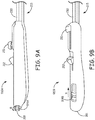
- Figure 2A is a side view of a delivery tool 1200 for an implantable medical device, according to some embodiments; and Figures 2B-C are enlarged views of a distal end of tool 1200, with a partial cut-away section view, according to some embodiments.
- Figure 2A illustrates tool 1200 including a handle assembly 210 and an elongate deployment tube 230 surrounded by an outer, stabilizing sheath 250 in proximity to handle assembly 210.
- Figure 2A further illustrates deployment tube 230 including a distal-most portion 232, which is sized to enclose an implantable medical device 2100, for example, as shown in Figure 2B .
- Deployment tube 230 extends around another elongate tube 320, which can be seen in Figures 2B-C ; tube 320 is part of an inner assembly 300, for example, as shown in Figures 3A-B .
- Figure 2A further illustrates handle assembly 210 including a flushing subassembly 215 to which a saline-filled syringe may be attached, for example, for flushing air from deployment tube 320 and/or from a lumen 304 ( Figure 3B ) of tube 320.
- Figure 3A is a plan view inner assembly 300, according to some embodiments; and Figure 3B is a cross-section view through section line B-B of Figure 3A , according to some embodiments.
- Figures 2B-C and 3A-B illustrate inner assembly 300 further including a distal member 322, which is coupled to a distal end 32 of tube 320, and which is configured to conform to a proximal end 2101 of device 2100 ( Figure 4A ).
- distal-most portion 232 defines a distal opening 203 of deployment tube 230.
- deployment tube 230 is coupled to a control member 211 of handle assembly 210, which is operable, per arrow A, to retract, or withdraw tube 230 relative to stabilizing sheath 250 and inner assembly 300, per arrow W, so that device 2100 may be deployed through distal opening 203 for implant in a body of a patient, for example, within the right ventricle RV ( Figure 1 ).
- Figures 2B-C and 3A-B further illustrate inner assembly 300 including a pull wire 325, which may extend within a longitudinally extending lumen 305 defined by tube 320, from a proximal end 31 thereof, which is coupled to another control member 212 of handle assembly 210, to a distal end that is anchored in proximity to distal end 32 of tube 320.
- Pull wire 325 may be a medical grade stainless steel wire with a fluoropolymer coating having a diameter of approximately 0.2286 mm (0.009 inch), and a diameter of lumen 305 may be approximately 03556 mm (0.014 inch).
- control member 212 when moved per arrow B, actuates pull wire 325 to bend inner assembly 300 and deployment tube 230, for example, to help navigate distal opening 203 of deployment tube 230 into proximity with a target implant site.
- device 2100 like device 100 described above, includes hermetically sealed enclosure 105, which contains a pulse generator, electrode 111, and fixation member 115.
- tool 1200 includes a tether assembly 400, which, according to Figures 3A-B , includes an elongate shaft 410 extending within lumen 304 defined by elongate tube 320 of inner assembly 300, and out through a proximal port 201 of handle assembly 210.
- a knob 405 of tether assembly 400 is shown coupled to a proximal end 411 of shaft 410, outside handle assembly 210, and, in Figure 4A , an attachment member 420 of tether assembly 400 is shown coupled to a distal end 412 of shaft 410.
- knob 405 is coupled to shaft 410 by a removable attachment, for example, a spring-loaded clamping mechanism, so that knob 405 may be temporarily removed from tether assembly 400 so that shaft 410 can be back-loaded into lumen 304 by inserting proximal end 411 in through a distal opening thereof formed by distal member 322.
- elongate tube 320 of inner assembly 300 is formed from bi-lumen tubing, for example, being extruded polyether block amide, polyurethane, or silicone rubber, or a composite thereof, and may include an overlay (not shown), for example, formed of braid-reinforced polyether block amide.
- Deployment tube 230 may be any suitable construction known in the art, for example, including varying durometers of polyether block amide to achieve a graduated flexibility and the necessary pushability and torque transfer that facilitates the maneuverability of tool 1200 to a target implant site.
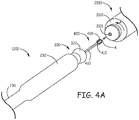
- Figure 4A is a perspective view of a distal portion of delivery tool 1200 and a proximal end 2101 of medical device 2100, wherein each is positioned for loading device 2100 into distal-most portion 232 of deployment tube 230.
- Figure 4A illustrates deployment tube 230 withdrawn relative to inner assembly 300 so distal member 322 is exposed, and attachment member 420 tether assembly 400 is exposed for mating together with a threaded attachment bore 2121 of device 2100.
- enlarged distal-most portion 232 has an inner diameter of approximately 0.7 cm (-0.275 inch) and an outer diameter of approximately 0.8 cm (-0.3 inch), and may extend over a length of approximately 1.4 inch (-3.5 cm).
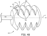
- Figure 4B is an enlarged perspective view of tether assembly attachment member 420, according to some embodiments.
- Figure 4B illustrates attachment member 420 formed by an external thread, which is configured to mate with threaded attachment bore 2121 of medical device 2100, and which is defined by a peak 426 and a corresponding valley 423 that helically extend around longitudinal axis 4.
- Figure 4A further illustrates attachment member 420 including an end wall 427 that joins adjacent proximal sections 46 of peak 426 to terminate a proximal end 43 of valley 423.
- end wall 427 extends orthogonally with respect to a direction of travel T within valley 423 to provide a hard stop for threaded attachment bore 2121 of device 2100, when bore 2121 is mated with the external thread, as described above.
- end wall 427 prevents a wedging together of the mating threads when tightened together to the maximum depth, so that an undue amount of torque is not necessary to later detach tether assembly 400 from device 2100, as will be described below.
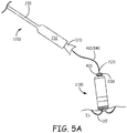
- Figures 5A-B are schematics showing delivery tool 1200 following deployment of implantable medical device 2100 at an implant site IS, according to some embodiments.
- Figure 5A illustrates tool 1200 having been withdrawn, relative to tether assembly 400, which remains attached to device 2100, to expose a distal section of shaft 410 in proximity to attachment member 420, for example, while an operator evaluates performance of device 2100 at implant site IS.
- the distal section of tether assembly shaft 410 is sufficiently flexible so that the attachment thereof to device 2100 does not tug on implanted device 2100 to significantly impact the stability or orientation thereof, for example, as fixed in place via fixation member 115.
- shaft 410 does not prevent tether assembly shaft 410 from transferring torque, per arrows CCW, from knob 405 to attachment member 420, so that the operator can detach tether assembly 400 from device 2100 by applying the torque to knob 405.
- end wall 427 of attachment member 420 prevented wedging together of the mating threads of device 2100 and assembly 400, the torque that the operator applies to knob 405 for detachment readily rotates attachment member 420 relative to device attachment bore 2121, without being transferred through device fixation member 115 to compromise the implant.
- knob 405 is too large to fit within lumen 304 of tube 320 ( Figures 3A-B ) and is coupled to shaft 410 by a removable attachment
- the operator has an option to keep implanted device 2100 tethered while withdrawing delivery tool 1200 out from the patient's body and over shaft 410 after removing knob 405 therefrom.
- knob 405 and attachment member 420 are both too big to fit within lumen 304
- the operator has an option to remove tether assembly 400 out from lumen 304, after knob 410 is removed from proximal end 411 of shaft 410, and then replace it with a snare assembly that can be employed to retrieve implanted device 2100, if necessary.
- tether assembly shaft 410 is formed, at least in part, from a cable 540, for example, as illustrated in Figure 5C.
- Figure 5C is a perspective view of a portion of cable 540, which shows cable 540 being formed from a plurality of wires 54 wrapped, or wound together in a single direction, counter clockwise (CCW), which, being the same as the direction of the application torque, per arrows CCW of Figure 5B , maximizes the torque response of shaft 410 in detaching tether assembly 400 from device 2100.
- CCW counter clockwise
- Attachment member 420 of tether assembly 400 may be joined to cable 540 by any suitable method known to those skilled in the art, but in some preferred embodiments, a weld joint is employed for the junction, to maintain a uniform diameter along a length of assembly 400.
- cable 540 has an outer diameter of approximately 0.254 mm (0.010 inch) and a 1x19 configuration known in the art, wherein nineteen medical grade stainless steel wires 54 each have an outer diameter of approximately 0.0381 mm (0.0015 inch).
- inner assembly tube 320 is positioned relative to attachment member 420 to support shaft 410 for the above-described application of torque; thus when the outer diameter of shaft 410 is approximately 0.254 mm (0.010 inch), a diameter of lumen 304 of inner assembly tube 320 is approximately 0.3048 mm (0.012 inch).
- a tether assembly shaft including cable 540 is formed in two sections, proximal and distal, to maintain a balance between flexibility and torque transfer, without having to rely on lumen 304 for torque-transfer support; thus lumen 304 of inner assembly tube 320 may have a larger diameter, for example, being approximately 1.067 mm (0.042 inch), to accommodate other assemblies in lieu of tether assembly 400, for example, a snare assembly.
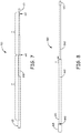
- Figures 6A-B are plan views of tether assemblies 600A, 600B, which each include a proximal shaft section P and a distal shaft section D, wherein proximal shaft section P is stiffer than distal shaft section D.
- Figure 6A illustrates proximal shaft section P of assembly 600A being formed by a structure 650 that is separate from cable 540 of distal shaft section D.
- Structure 650 may be a medical grade stainless steel wire or hypo-tube that has an outer diameter of approximately 0.508 mm (0.020 inch).
- Figure 6A further illustrates a weld joint 645 attaching cable 540 to structure 650.
- Figure 6B illustrates proximal shaft section P of assembly 600B being formed by a polymer jacket 640, for example, a polyimide, overlaying a proximal length of cable 540.
- Jacket 640 may be formed around cable 540 by co-extrusion or a shrink fit.
- An outer diameter of proximal shaft section P of assembly 600B may be approximately 0.762 mm (0.030 inch).
- a length of proximal shaft section is between approximately 100 cm and 140 cm, and a length of distal shaft section D is between approximately 20 cm and 26 cm.
- Figure 7 is a plan view of another tether assembly 700, according to some alternate embodiments, which also includes proximal shaft section P being stiffer than distal shaft section D.
- Figure 7 illustrates a tapered mandrel 750 (e.g., medical grade stainless steel wire) forming proximal shaft section P and distal shaft section D of assembly 700.
- a tapered mandrel 750 e.g., medical grade stainless steel wire
- Proximal shaft section P of assembly 700 may have a single diameter, for example, between approximately 0.254 mm (0.010 inch) and approximately 0.508 mm (0.020 inch), or may taper from a larger diameter (e.g., -0.508 mm (0.020 inch)), in proximity to knob 405, to a smaller diameter (e.g., -0.254 mm (0.010 inch)), in proximity to distal shaft section D; and distal shaft section D of assembly 700 tapers from a larger diameter, for example, between approximately 0.010 inch and approximately 0.254 mm (0.020 inch), to a smaller diameter, for example, approximately 0.0762 mm (0.003 inch).
- Attachment member 420 and knob 405 may be welded, crimped, or otherwise joined to opposing ends of tapered mandrel 750 according to methods known in the art.
- Figure 8 is a plan view of yet another tether assembly 800, according to some additional embodiments.
- Figure 8 illustrates assembly 800 including a relatively flexible shaft 840 around which a stiffening tube 860 is slideably engaged.
- a proximal end 861 of stiffening tube 860 is accessible outside handle assembly 210, proximal to proximal port 201 thereof ( Figures 2A and 5B ), so that the operator can slide tube 860 distally over flexible shaft 840, per arrow S, to provide torque-transfer support thereto, in proximity to attachment member 420.
- delivery tool 1200 is first withdrawn relative to flexible shaft 840 to expose a distal length thereof without the support of stiffening tube 860, for example, as illustrated in Figure 5A , for the evaluation of device performance, as described above. Then, if the device performance is deemed acceptable, the operator can advance stiffening tube 860 distally over the distal length of shaft 840, to provide the torque-transfer support thereto while applying the torque to knob 405 that detaches tether assembly 800 from implanted device 2100.
- Figures 9A-B are perspective views of handle assemblies 910A, 910B, each of which may be incorporated by delivery tool 1200, in lieu handle assembly 210, according to alternate embodiments.
- Handle assemblies 910A, 910B are similar to handle assembly 210 in that each includes control members 211, 212, flushing subassembly 215, and proximal port 201.
- Figure 9A illustrates handle assembly 910A including a control member 914A for a valve member thereof, wherein the valve member is a Tuohy-bourst type known in the art so that control member 914A rotates, per arrow R, to open and close the valve member.
- Figure 9B illustrates handle assembly 910B including a control member 914B for a valve member thereof, wherein the valve member is a relatively soft tube that is collapsed by sliding control member 914B per arrow S.
- a proximal end 321 of inner assembly tube 320 is fixed within handle assembly 910A, 910B, in proximity to the valve member thereof, such that lumen 304 is in-line with the valve member, and shaft 410 of tether assembly 400 (alternately proximal shaft section P of any of tether assemblies 600A, 600B, 700, or stiffening tube 860 around flexible shaft 840 of tether assembly 800) extends through the valve member and out through proximal port 201.
- valve member of either handle assembly 910A, 910B, is operable, when closed, to seal around the shaft (or stiffening tube) of any of the above-described tether assemblies 400, 600A, 600B, 700, 800, and, when opened, to allow movement of the tether assembly therethrough, wherein control member 914A of handle assembly 910A rotates around the longitudinal axis of the tether assembly to open and close the corresponding valve member around the shaft thereof, and wherein control member 914B slides along the longitudinal axis to open and close the corresponding valve member around the shaft of the tether assembly.
Landscapes
- Health & Medical Sciences (AREA)
- Life Sciences & Earth Sciences (AREA)
- Heart & Thoracic Surgery (AREA)
- Engineering & Computer Science (AREA)
- Biomedical Technology (AREA)
- Nuclear Medicine, Radiotherapy & Molecular Imaging (AREA)
- Animal Behavior & Ethology (AREA)
- General Health & Medical Sciences (AREA)
- Public Health (AREA)
- Veterinary Medicine (AREA)
- Radiology & Medical Imaging (AREA)
- Cardiology (AREA)
- Vascular Medicine (AREA)
- Surgery (AREA)
- Pathology (AREA)
- Medical Informatics (AREA)
- Molecular Biology (AREA)
- Prostheses (AREA)
Claims (10)
- Halterungsanordnung für eine implantierbare medizinische Vorrichtung, wobei die medizinische Vorrichtung ein hermetisches Gehäuse, einen in dem Gehäuse enthaltenen Impulsgenerator, ein an ein distales Ende des Gehäuses gekoppeltes Fixierelement und eine in der Nähe eines proximalen Endes des Gehäuses befindliche, mit Gewinde versehene Befestigungsbohrung (1212) beinhaltet und wobei die Halterungsanordnung Folgendes umfasst:einen länglichen Schaft (410), der sich von einem proximalen Ende (411) davon zu einem distalen Ende (412) davon erstreckt;ein an das distale Ende des Schafts gekoppeltes Befestigungselement, wobei das Befestigungselement ein Außengewinde und eine Endwand beinhaltet, wobei das Außengewinde durch eine sich schraubenförmig erstreckende Spitze (426) und ein entsprechendes Tal (423) definiert ist,einen Knopf (405), der an das proximale Ende des Schafts gekoppelt ist; undwobei der Schaft ein auf den Knopf ausgeübtes Drehmoment von dem Knopf auf das Befestigungselement überträgt, um die Halterung von der Bohrung der medizinischen Vorrichtung zu lösen; und dadurch gekennzeichnet, dass die Endwand (427) benachbarte proximale Abschnitte der Spitze verbindet, um ein proximales Ende des Tals zu begrenzen, wobei sich die Endwand orthogonal in Bezug auf eine Bewegungsrichtung innerhalb des Tals erstreckt, um einen harten Anschlag für die mit Gewinde versehene Befestigungsbohrung der medizinischen Vorrichtung bereitzustellen, wenn die Bohrung mit dem Außengewinde in Eingriff gebracht wird.
- Anordnung nach Anspruch 1, wobei der Schaft ein Kabel (540) umfasst, das durch eine Vielzahl von Drähten (54) gebildet ist, die in einer einzigen Richtung zusammen gewickelt sind, wobei die Richtung diejenige ist, in der das Drehmoment auf den Knopf der Halterungsanordnung ausgeübt wird, um die Halterungsanordnung von der Bohrung der medizinischen Vorrichtung zu lösen.
- Anordnung nach einem der Ansprüche 1 oder 2, wobei:der Schaft einen proximalen Abschnitt (P) und einen distalen Abschnitt (D) beinhaltet;sich der proximale Abschnitt von dem proximalen Ende des Schafts zu dem distalen Abschnitt erstreckt, wobei er durch einen einzelnen Draht oder eine Hyporöhre gebildet ist, an der das Kabel befestigt ist; undsich der distale Abschnitt von dem proximalen Abschnitt zu dem distalen Ende des Schafts erstreckt, wobei er durch das Kabel gebildet ist.
- Anordnung nach einem der Ansprüche 1-3, wobei:sich das Kabel entlang einer gesamten Länge des Schafts erstreckt; undder Schaft ferner einen Polymermantel umfasst, der sich nur entlang einer proximalen Länge des Schafts um das Kabel herum erstreckt.
- Anordnung nach einem der Ansprüche 1-4, wobei:der Schaft einen Dorn (750) und ein Versteifungsrohr (860) umfasst, das sich um diesen herum erstreckt, wobei sich der Dorn entlang einer gesamten Länge des Schaftes erstreckt, und eine Länge des Versteifungsrohrs kleiner als die des Dorns ist; unddas Versteifungsrohr entlang der Länge des Dorns zwischen dem proximalen Ende und dem distalen Ende des Schafts gleitet.
- Anordnung nach einem der Ansprüche 1-5, wobei der Schaft einen sich verjüngenden Dorn (750) umfasst, der sich entlang einer gesamten Länge des Schaftes erstreckt, wobei sich der Dorn von einem ersten Außendurchmesser entlang eines proximalen Abschnitts davon zu einem zweiten Außendurchmesser am distalen Ende des Schafts erstreckt, wobei der zweite Durchmesser kleiner als der erste Durchmesser ist.
- Anordnung nach Anspruch 1, wobei der Knopf durch eine entfernbare Befestigung an den Schaft gekoppelt ist.
- Abgabeinstrument (1200) für eine implantierbare medizinische Vorrichtung, wobei die medizinische Vorrichtung ein hermetisches Gehäuse (105), einen in dem Gehäuse enthaltenen Impulsgenerator, ein an ein distales Ende des Gehäuses gekoppeltes Fixierelement (115) und eine in der Nähe eines proximalen Endes des Gehäuses befindliche, mit Gewinde versehene Befestigungsbohrung beinhaltet und wobei das Instrument Folgendes umfasst:eine Griffanordnung (210) mit einem ersten Steuerelement (211), einem zweiten Steuerelement (212), einem proximalen Anschluss und einem Ventilelement, das an das zweite Steuerelement gekoppelt ist und an dem proximalen Anschluss ausgerichtet ist;eine innere Anordnung (300) mit einem länglichen Rohr (320) und einem distalen Element (322), wobei das Rohr ein proximales Ende (31) beinhaltet, das in der Griffanordnung in der Nähe des Ventilelements fixiert ist, wobei das Rohr ein sich in Längsrichtung erstreckendes Lumen definiert, wobei das Lumen an dem Ventilelement ausgerichtet ist und das distale Element an ein distales Ende (32) des Rohrs gekoppelt ist, wobei das distale Element eine distale Öffnung des Lumens definiert und so konfiguriert ist, dass es dem proximalen Ende des hermetischen Gehäuses der medizinischen Vorrichtung entspricht;ein äußeres längliches Einsatzrohr (230), das sich um das Rohr der inneren Anordnung herum erstreckt und in Längsrichtung über das erste Steuerelement der Griffanordnung relativ zu der inneren Anordnung bewegbar ist, wobei das Einsatzrohr einen am weitesten distal gelegenen Abschnitt beinhaltet, der eine distale Öffnung (203) des Einsatzrohrs definiert und so bemessen ist, dass er die medizinische Vorrichtung und das distale Element der inneren Anordnung umschließt; undeine Halterungsanordnung (400) nach einem der vorhergehenden Ansprüche.
- Instrument nach Anspruch 8, wobei sich das zweite Steuerelement (212) der Griffanordnung um die Längsachse dreht, um das Ventilelement um den Schaft der Halterungsordnung herum zu öffnen und zu schließen.
- Instrument nach einem der Ansprüche 8 oder 9, wobei das zweite Steuerelement (212) der Griffanordnung entlang der Längsachse gleitet, um das Ventilelement um den Schaft der Halterungsanordnung herum zu öffnen und zu schließen.
Applications Claiming Priority (2)
| Application Number | Priority Date | Filing Date | Title |
|---|---|---|---|
| US14/598,346 US20160206872A1 (en) | 2015-01-16 | 2015-01-16 | Interventional medical tools and assemblies |
| PCT/US2016/013347 WO2016115308A1 (en) | 2015-01-16 | 2016-01-14 | Interventional medical tools and assemblies |
Publications (2)
| Publication Number | Publication Date |
|---|---|
| EP3244967A1 EP3244967A1 (de) | 2017-11-22 |
| EP3244967B1 true EP3244967B1 (de) | 2018-12-19 |
Family
ID=55221578
Family Applications (1)
| Application Number | Title | Priority Date | Filing Date |
|---|---|---|---|
| EP16701398.6A Active EP3244967B1 (de) | 2015-01-16 | 2016-01-14 | Interventionelle medizinische instrumente und anordnungen |
Country Status (4)
| Country | Link |
|---|---|
| US (1) | US20160206872A1 (de) |
| EP (1) | EP3244967B1 (de) |
| CN (1) | CN107106849B (de) |
| WO (1) | WO2016115308A1 (de) |
Families Citing this family (17)
| Publication number | Priority date | Publication date | Assignee | Title |
|---|---|---|---|---|
| EP3377174B1 (de) | 2015-11-20 | 2019-08-28 | Cardiac Pacemakers, Inc. | Abgabesysteme für elektrodenlose herzvorrichtungen |
| WO2017087661A1 (en) | 2015-11-20 | 2017-05-26 | Cardiac Pacemakers, Inc. | Delivery devices and methods for leadless cardiac devices |
| EP3541460B1 (de) | 2016-11-21 | 2020-12-23 | Cardiac Pacemakers, Inc. | Einführvorrichtungen und wandappositionsabtastung |
| US11198013B2 (en) | 2016-11-21 | 2021-12-14 | Cardiac Pacemakers, Inc. | Catheter and leadless cardiac devices including electrical pathway barrier |
| US10806931B2 (en) | 2016-12-27 | 2020-10-20 | Cardiac Pacemakers, Inc. | Delivery devices and methods for leadless cardiac devices |
| WO2018125791A1 (en) | 2016-12-27 | 2018-07-05 | Cardiac Pacemakers, Inc. | Leadless delivery catheter with conductive pathway |
| CN110114114B (zh) | 2016-12-27 | 2023-05-02 | 心脏起搏器股份公司 | 用于无引线心脏装置的递送装置和方法 |
| US10485981B2 (en) | 2016-12-27 | 2019-11-26 | Cardiac Pacemakers, Inc. | Fixation methods for leadless cardiac devices |
| CN110225779B (zh) | 2017-01-26 | 2023-04-04 | 心脏起搏器股份公司 | 用于无引线心脏装置的递送装置 |
| WO2018165377A1 (en) | 2017-03-10 | 2018-09-13 | Cardiac Pacemakers, Inc. | Fixation for leadless cardiac devices |
| US10737092B2 (en) | 2017-03-30 | 2020-08-11 | Cardiac Pacemakers, Inc. | Delivery devices and methods for leadless cardiac devices |
| US11577085B2 (en) | 2017-08-03 | 2023-02-14 | Cardiac Pacemakers, Inc. | Delivery devices and methods for leadless cardiac devices |
| CN108434600B (zh) | 2018-02-26 | 2021-11-02 | 郭成军 | 心腔内植入物、心脏起搏器、植入装置 |
| US11446510B2 (en) | 2019-03-29 | 2022-09-20 | Cardiac Pacemakers, Inc. | Systems and methods for treating cardiac arrhythmias |
| CN113660977A (zh) | 2019-03-29 | 2021-11-16 | 心脏起搏器股份公司 | 用于治疗心律失常的系统和方法 |
| CN114364431A (zh) | 2019-09-11 | 2022-04-15 | 心脏起搏器股份公司 | 用于植入和/或取回具有螺旋固定件的无导线心脏起搏装置的工具和系统 |
| US11571582B2 (en) | 2019-09-11 | 2023-02-07 | Cardiac Pacemakers, Inc. | Tools and systems for implanting and/or retrieving a leadless cardiac pacing device with helix fixation |
Family Cites Families (25)
| Publication number | Priority date | Publication date | Assignee | Title |
|---|---|---|---|---|
| US7033339B1 (en) * | 1998-05-29 | 2006-04-25 | Becton Dickinson And Company (Part Interest) | Self sealing luer receiving stopcock |
| US6913614B2 (en) * | 2003-05-08 | 2005-07-05 | Cardia, Inc. | Delivery system with safety tether |
| US7763012B2 (en) * | 2003-09-02 | 2010-07-27 | St. Jude Medical, Cardiology Division, Inc. | Devices and methods for crossing a chronic total occlusion |
| EP1663354A1 (de) * | 2003-09-03 | 2006-06-07 | Novo Nordisk A/S | Gewindenstangen und mutter- anordnung |
| US20080119785A1 (en) * | 2004-08-11 | 2008-05-22 | Maynard Ramsey | Enhanced system and method for wound track navigation and hemorrhage control |
| CN100464619C (zh) * | 2005-04-29 | 2009-02-25 | 深圳富泰宏精密工业有限公司 | 铰链结构 |
| EP2471452B1 (de) * | 2005-10-14 | 2014-12-10 | Pacesetter, Inc. | Leitungsloser Herzschrittmacher und System |
| CN101466316B (zh) * | 2005-10-20 | 2012-06-27 | 阿普特斯内系统公司 | 包括使用固定件工具的用于修复物递送和植入的装置、系统和方法 |
| US8364281B2 (en) * | 2008-11-07 | 2013-01-29 | W. L. Gore & Associates, Inc. | Implantable lead |
| JP5572637B2 (ja) * | 2008-12-22 | 2014-08-13 | クック メディカル テクノロジーズ エルエルシー | 電気外科回転切開器具 |
| US9566082B2 (en) * | 2009-05-22 | 2017-02-14 | Slatr Surgical Holdings Llc | Endoscopic instrument |
| US20120095539A1 (en) * | 2010-10-13 | 2012-04-19 | Alexander Khairkhahan | Delivery Catheter Systems and Methods |
| US8926588B2 (en) * | 2011-07-05 | 2015-01-06 | Medtronic Vascular, Inc. | Steerable delivery catheter |
| US8945145B2 (en) * | 2011-09-22 | 2015-02-03 | Medtronic, Inc. | Delivery system assemblies for implantable medical devices |
| US8945146B2 (en) * | 2011-10-24 | 2015-02-03 | Medtronic, Inc. | Delivery system assemblies and associated methods for implantable medical devices |
| US8721587B2 (en) * | 2011-11-17 | 2014-05-13 | Medtronic, Inc. | Delivery system assemblies and associated methods for implantable medical devices |
| US9216293B2 (en) * | 2011-11-17 | 2015-12-22 | Medtronic, Inc. | Delivery system assemblies for implantable medical devices |
| US9439747B2 (en) * | 2012-02-22 | 2016-09-13 | Boston Scientific Scimed, Inc. | Adjustable medical assembly for implant tension adjustment |
| US9570871B2 (en) * | 2012-06-28 | 2017-02-14 | Shanghai Microport Medical (Group) Co., Ltd. | Assembly of active cardiac electrical lead |
| US20140018818A1 (en) * | 2012-07-12 | 2014-01-16 | Pacesetter, Inc. | System and method of implanting a medical device |
| US9351648B2 (en) * | 2012-08-24 | 2016-05-31 | Medtronic, Inc. | Implantable medical device electrode assembly |
| US9174023B2 (en) * | 2013-01-07 | 2015-11-03 | Biosense Webster (Israel) Ltd. | Unidirectional catheter control handle with tensioning control |
| JP5627732B2 (ja) * | 2013-04-22 | 2014-11-19 | サーモス株式会社 | 飲料用容器の栓体 |
| EP2818202B1 (de) * | 2013-06-24 | 2016-04-13 | Sorin CRM SAS | Anschlusssystem zwischen einer medizinischen Vorrichtung und ihrem Implantationszubehörteil in situ |
| JP6151161B2 (ja) * | 2013-11-29 | 2017-06-21 | 株式会社ショーワ | ボールねじおよびパワーステアリング装置 |
-
2015
- 2015-01-16 US US14/598,346 patent/US20160206872A1/en not_active Abandoned
-
2016
- 2016-01-14 EP EP16701398.6A patent/EP3244967B1/de active Active
- 2016-01-14 WO PCT/US2016/013347 patent/WO2016115308A1/en active Application Filing
- 2016-01-14 CN CN201680005906.XA patent/CN107106849B/zh active Active
Also Published As
| Publication number | Publication date |
|---|---|
| EP3244967A1 (de) | 2017-11-22 |
| CN107106849B (zh) | 2020-06-12 |
| WO2016115308A1 (en) | 2016-07-21 |
| CN107106849A (zh) | 2017-08-29 |
| US20160206872A1 (en) | 2016-07-21 |
Similar Documents
| Publication | Publication Date | Title |
|---|---|---|
| EP3244967B1 (de) | Interventionelle medizinische instrumente und anordnungen | |
| EP3448510B1 (de) | Interventionelle medizinische systeme und verbesserte anordnungen davon und zugehörige verfahren zur verwendung | |
| US10130821B2 (en) | Interventional medical systems and associated tethering assemblies and methods | |
| EP3193998B1 (de) | Interventionelle medizinische systeme | |
| EP3448490B1 (de) | Interventionelle medizinische systeme und zugehörige anordnungen | |
| EP2780077B1 (de) | Baugruppen für ein abgabesystem für implantierbare medizinische vorrichtungen | |
| EP3194019B1 (de) | Interventionelle medizinische systeme, werkzeuge und verfahren zur verwendung | |
| EP3125990B1 (de) | Interventionelle medizinische systeme, werkzeuge und zugehörige verfahren | |
| EP3062875B1 (de) | Werkzeuge und anordnungen davon für implantierbare medizinische vorrichtungen | |
| US8504156B2 (en) | Holding members for implantable cardiac stimulation devices | |
| US20170043158A1 (en) | Interventional medical systems and catheters | |
| US20180028805A1 (en) | Interventional medical systems and associated tethering assemblies and methods | |
| WO2018080470A1 (en) | Interventional medical systems and catheters | |
| US20160095611A1 (en) | Explantation accessory for an intracorporeal capsule | |
| EP4370199A1 (de) | Haltegurtanordnungen für rückholsysteme für medizinische vorrichtungen |
Legal Events
| Date | Code | Title | Description |
|---|---|---|---|
| STAA | Information on the status of an ep patent application or granted ep patent |
Free format text: STATUS: THE INTERNATIONAL PUBLICATION HAS BEEN MADE |
|
| PUAI | Public reference made under article 153(3) epc to a published international application that has entered the european phase |
Free format text: ORIGINAL CODE: 0009012 |
|
| STAA | Information on the status of an ep patent application or granted ep patent |
Free format text: STATUS: REQUEST FOR EXAMINATION WAS MADE |
|
| 17P | Request for examination filed |
Effective date: 20170816 |
|
| AK | Designated contracting states |
Kind code of ref document: A1 Designated state(s): AL AT BE BG CH CY CZ DE DK EE ES FI FR GB GR HR HU IE IS IT LI LT LU LV MC MK MT NL NO PL PT RO RS SE SI SK SM TR |
|
| AX | Request for extension of the european patent |
Extension state: BA ME |
|
| DAV | Request for validation of the european patent (deleted) | ||
| DAX | Request for extension of the european patent (deleted) | ||
| GRAP | Despatch of communication of intention to grant a patent |
Free format text: ORIGINAL CODE: EPIDOSNIGR1 |
|
| STAA | Information on the status of an ep patent application or granted ep patent |
Free format text: STATUS: GRANT OF PATENT IS INTENDED |
|
| RIC1 | Information provided on ipc code assigned before grant |
Ipc: A61N 1/372 20060101AFI20180625BHEP Ipc: A61N 1/375 20060101ALI20180625BHEP Ipc: A61B 17/34 20060101ALI20180625BHEP Ipc: A61N 1/04 20060101ALI20180625BHEP Ipc: A61M 25/06 20060101ALI20180625BHEP Ipc: A61N 1/05 20060101ALI20180625BHEP |
|
| INTG | Intention to grant announced |
Effective date: 20180716 |
|
| RIN1 | Information on inventor provided before grant (corrected) |
Inventor name: MCDONNELL, PAULA Inventor name: WARD, SEAN Inventor name: MCHUGH, PAT Inventor name: WOOD, RONAN |
|
| GRAS | Grant fee paid |
Free format text: ORIGINAL CODE: EPIDOSNIGR3 |
|
| GRAA | (expected) grant |
Free format text: ORIGINAL CODE: 0009210 |
|
| STAA | Information on the status of an ep patent application or granted ep patent |
Free format text: STATUS: THE PATENT HAS BEEN GRANTED |
|
| AK | Designated contracting states |
Kind code of ref document: B1 Designated state(s): AL AT BE BG CH CY CZ DE DK EE ES FI FR GB GR HR HU IE IS IT LI LT LU LV MC MK MT NL NO PL PT RO RS SE SI SK SM TR |
|
| REG | Reference to a national code |
Ref country code: GB Ref legal event code: FG4D |
|
| REG | Reference to a national code |
Ref country code: CH Ref legal event code: EP |
|
| REG | Reference to a national code |
Ref country code: IE Ref legal event code: FG4D |
|
| REG | Reference to a national code |
Ref country code: DE Ref legal event code: R096 Ref document number: 602016008432 Country of ref document: DE |
|
| REG | Reference to a national code |
Ref country code: AT Ref legal event code: REF Ref document number: 1078023 Country of ref document: AT Kind code of ref document: T Effective date: 20190115 |
|
| REG | Reference to a national code |
Ref country code: NL Ref legal event code: MP Effective date: 20181219 |
|
| PG25 | Lapsed in a contracting state [announced via postgrant information from national office to epo] |
Ref country code: FI Free format text: LAPSE BECAUSE OF FAILURE TO SUBMIT A TRANSLATION OF THE DESCRIPTION OR TO PAY THE FEE WITHIN THE PRESCRIBED TIME-LIMIT Effective date: 20181219 Ref country code: LV Free format text: LAPSE BECAUSE OF FAILURE TO SUBMIT A TRANSLATION OF THE DESCRIPTION OR TO PAY THE FEE WITHIN THE PRESCRIBED TIME-LIMIT Effective date: 20181219 Ref country code: HR Free format text: LAPSE BECAUSE OF FAILURE TO SUBMIT A TRANSLATION OF THE DESCRIPTION OR TO PAY THE FEE WITHIN THE PRESCRIBED TIME-LIMIT Effective date: 20181219 Ref country code: NO Free format text: LAPSE BECAUSE OF FAILURE TO SUBMIT A TRANSLATION OF THE DESCRIPTION OR TO PAY THE FEE WITHIN THE PRESCRIBED TIME-LIMIT Effective date: 20190319 Ref country code: BG Free format text: LAPSE BECAUSE OF FAILURE TO SUBMIT A TRANSLATION OF THE DESCRIPTION OR TO PAY THE FEE WITHIN THE PRESCRIBED TIME-LIMIT Effective date: 20190319 Ref country code: LT Free format text: LAPSE BECAUSE OF FAILURE TO SUBMIT A TRANSLATION OF THE DESCRIPTION OR TO PAY THE FEE WITHIN THE PRESCRIBED TIME-LIMIT Effective date: 20181219 |
|
| REG | Reference to a national code |
Ref country code: LT Ref legal event code: MG4D |
|
| REG | Reference to a national code |
Ref country code: AT Ref legal event code: MK05 Ref document number: 1078023 Country of ref document: AT Kind code of ref document: T Effective date: 20181219 |
|
| PG25 | Lapsed in a contracting state [announced via postgrant information from national office to epo] |
Ref country code: AL Free format text: LAPSE BECAUSE OF FAILURE TO SUBMIT A TRANSLATION OF THE DESCRIPTION OR TO PAY THE FEE WITHIN THE PRESCRIBED TIME-LIMIT Effective date: 20181219 Ref country code: GR Free format text: LAPSE BECAUSE OF FAILURE TO SUBMIT A TRANSLATION OF THE DESCRIPTION OR TO PAY THE FEE WITHIN THE PRESCRIBED TIME-LIMIT Effective date: 20190320 Ref country code: SE Free format text: LAPSE BECAUSE OF FAILURE TO SUBMIT A TRANSLATION OF THE DESCRIPTION OR TO PAY THE FEE WITHIN THE PRESCRIBED TIME-LIMIT Effective date: 20181219 Ref country code: RS Free format text: LAPSE BECAUSE OF FAILURE TO SUBMIT A TRANSLATION OF THE DESCRIPTION OR TO PAY THE FEE WITHIN THE PRESCRIBED TIME-LIMIT Effective date: 20181219 |
|
| PG25 | Lapsed in a contracting state [announced via postgrant information from national office to epo] |
Ref country code: NL Free format text: LAPSE BECAUSE OF FAILURE TO SUBMIT A TRANSLATION OF THE DESCRIPTION OR TO PAY THE FEE WITHIN THE PRESCRIBED TIME-LIMIT Effective date: 20181219 |
|
| PG25 | Lapsed in a contracting state [announced via postgrant information from national office to epo] |
Ref country code: IT Free format text: LAPSE BECAUSE OF FAILURE TO SUBMIT A TRANSLATION OF THE DESCRIPTION OR TO PAY THE FEE WITHIN THE PRESCRIBED TIME-LIMIT Effective date: 20181219 Ref country code: CZ Free format text: LAPSE BECAUSE OF FAILURE TO SUBMIT A TRANSLATION OF THE DESCRIPTION OR TO PAY THE FEE WITHIN THE PRESCRIBED TIME-LIMIT Effective date: 20181219 Ref country code: PT Free format text: LAPSE BECAUSE OF FAILURE TO SUBMIT A TRANSLATION OF THE DESCRIPTION OR TO PAY THE FEE WITHIN THE PRESCRIBED TIME-LIMIT Effective date: 20190419 Ref country code: PL Free format text: LAPSE BECAUSE OF FAILURE TO SUBMIT A TRANSLATION OF THE DESCRIPTION OR TO PAY THE FEE WITHIN THE PRESCRIBED TIME-LIMIT Effective date: 20181219 Ref country code: ES Free format text: LAPSE BECAUSE OF FAILURE TO SUBMIT A TRANSLATION OF THE DESCRIPTION OR TO PAY THE FEE WITHIN THE PRESCRIBED TIME-LIMIT Effective date: 20181219 |
|
| PG25 | Lapsed in a contracting state [announced via postgrant information from national office to epo] |
Ref country code: EE Free format text: LAPSE BECAUSE OF FAILURE TO SUBMIT A TRANSLATION OF THE DESCRIPTION OR TO PAY THE FEE WITHIN THE PRESCRIBED TIME-LIMIT Effective date: 20181219 Ref country code: SM Free format text: LAPSE BECAUSE OF FAILURE TO SUBMIT A TRANSLATION OF THE DESCRIPTION OR TO PAY THE FEE WITHIN THE PRESCRIBED TIME-LIMIT Effective date: 20181219 Ref country code: RO Free format text: LAPSE BECAUSE OF FAILURE TO SUBMIT A TRANSLATION OF THE DESCRIPTION OR TO PAY THE FEE WITHIN THE PRESCRIBED TIME-LIMIT Effective date: 20181219 Ref country code: SK Free format text: LAPSE BECAUSE OF FAILURE TO SUBMIT A TRANSLATION OF THE DESCRIPTION OR TO PAY THE FEE WITHIN THE PRESCRIBED TIME-LIMIT Effective date: 20181219 Ref country code: IS Free format text: LAPSE BECAUSE OF FAILURE TO SUBMIT A TRANSLATION OF THE DESCRIPTION OR TO PAY THE FEE WITHIN THE PRESCRIBED TIME-LIMIT Effective date: 20190419 |
|
| REG | Reference to a national code |
Ref country code: CH Ref legal event code: PL |
|
| REG | Reference to a national code |
Ref country code: DE Ref legal event code: R097 Ref document number: 602016008432 Country of ref document: DE |
|
| PG25 | Lapsed in a contracting state [announced via postgrant information from national office to epo] |
Ref country code: LU Free format text: LAPSE BECAUSE OF NON-PAYMENT OF DUE FEES Effective date: 20190114 |
|
| REG | Reference to a national code |
Ref country code: BE Ref legal event code: MM Effective date: 20190131 |
|
| PLBE | No opposition filed within time limit |
Free format text: ORIGINAL CODE: 0009261 |
|
| STAA | Information on the status of an ep patent application or granted ep patent |
Free format text: STATUS: NO OPPOSITION FILED WITHIN TIME LIMIT |
|
| PG25 | Lapsed in a contracting state [announced via postgrant information from national office to epo] |
Ref country code: DK Free format text: LAPSE BECAUSE OF FAILURE TO SUBMIT A TRANSLATION OF THE DESCRIPTION OR TO PAY THE FEE WITHIN THE PRESCRIBED TIME-LIMIT Effective date: 20181219 Ref country code: MC Free format text: LAPSE BECAUSE OF FAILURE TO SUBMIT A TRANSLATION OF THE DESCRIPTION OR TO PAY THE FEE WITHIN THE PRESCRIBED TIME-LIMIT Effective date: 20181219 Ref country code: AT Free format text: LAPSE BECAUSE OF FAILURE TO SUBMIT A TRANSLATION OF THE DESCRIPTION OR TO PAY THE FEE WITHIN THE PRESCRIBED TIME-LIMIT Effective date: 20181219 |
|
| 26N | No opposition filed |
Effective date: 20190920 |
|
| PG25 | Lapsed in a contracting state [announced via postgrant information from national office to epo] |
Ref country code: BE Free format text: LAPSE BECAUSE OF NON-PAYMENT OF DUE FEES Effective date: 20190131 |
|
| PG25 | Lapsed in a contracting state [announced via postgrant information from national office to epo] |
Ref country code: LI Free format text: LAPSE BECAUSE OF NON-PAYMENT OF DUE FEES Effective date: 20190131 Ref country code: CH Free format text: LAPSE BECAUSE OF NON-PAYMENT OF DUE FEES Effective date: 20190131 |
|
| PG25 | Lapsed in a contracting state [announced via postgrant information from national office to epo] |
Ref country code: SI Free format text: LAPSE BECAUSE OF FAILURE TO SUBMIT A TRANSLATION OF THE DESCRIPTION OR TO PAY THE FEE WITHIN THE PRESCRIBED TIME-LIMIT Effective date: 20181219 |
|
| PG25 | Lapsed in a contracting state [announced via postgrant information from national office to epo] |
Ref country code: TR Free format text: LAPSE BECAUSE OF FAILURE TO SUBMIT A TRANSLATION OF THE DESCRIPTION OR TO PAY THE FEE WITHIN THE PRESCRIBED TIME-LIMIT Effective date: 20181219 |
|
| PG25 | Lapsed in a contracting state [announced via postgrant information from national office to epo] |
Ref country code: MT Free format text: LAPSE BECAUSE OF NON-PAYMENT OF DUE FEES Effective date: 20190114 |
|
| GBPC | Gb: european patent ceased through non-payment of renewal fee |
Effective date: 20200114 |
|
| PG25 | Lapsed in a contracting state [announced via postgrant information from national office to epo] |
Ref country code: GB Free format text: LAPSE BECAUSE OF NON-PAYMENT OF DUE FEES Effective date: 20200114 |
|
| PG25 | Lapsed in a contracting state [announced via postgrant information from national office to epo] |
Ref country code: CY Free format text: LAPSE BECAUSE OF FAILURE TO SUBMIT A TRANSLATION OF THE DESCRIPTION OR TO PAY THE FEE WITHIN THE PRESCRIBED TIME-LIMIT Effective date: 20181219 |
|
| PG25 | Lapsed in a contracting state [announced via postgrant information from national office to epo] |
Ref country code: HU Free format text: LAPSE BECAUSE OF FAILURE TO SUBMIT A TRANSLATION OF THE DESCRIPTION OR TO PAY THE FEE WITHIN THE PRESCRIBED TIME-LIMIT; INVALID AB INITIO Effective date: 20160114 |
|
| PG25 | Lapsed in a contracting state [announced via postgrant information from national office to epo] |
Ref country code: MK Free format text: LAPSE BECAUSE OF FAILURE TO SUBMIT A TRANSLATION OF THE DESCRIPTION OR TO PAY THE FEE WITHIN THE PRESCRIBED TIME-LIMIT Effective date: 20181219 |
|
| PGFP | Annual fee paid to national office [announced via postgrant information from national office to epo] |
Ref country code: IE Payment date: 20231221 Year of fee payment: 9 Ref country code: FR Payment date: 20231219 Year of fee payment: 9 |
|
| PGFP | Annual fee paid to national office [announced via postgrant information from national office to epo] |
Ref country code: DE Payment date: 20231219 Year of fee payment: 9 |