EP3244047A1 - Verfahren zur steuerung einer kraftstoffpumpe für ein direkteinspritzsystem - Google Patents
Verfahren zur steuerung einer kraftstoffpumpe für ein direkteinspritzsystem Download PDFInfo
- Publication number
- EP3244047A1 EP3244047A1 EP17170405.9A EP17170405A EP3244047A1 EP 3244047 A1 EP3244047 A1 EP 3244047A1 EP 17170405 A EP17170405 A EP 17170405A EP 3244047 A1 EP3244047 A1 EP 3244047A1
- Authority
- EP
- European Patent Office
- Prior art keywords
- high pressure
- pressure pump
- flow rate
- fuel
- common rail
- Prior art date
- Legal status (The legal status is an assumption and is not a legal conclusion. Google has not performed a legal analysis and makes no representation as to the accuracy of the status listed.)
- Granted
Links
- 239000000446 fuel Substances 0.000 title claims abstract description 81
- 238000000034 method Methods 0.000 title claims abstract description 18
- 238000002347 injection Methods 0.000 title claims abstract description 15
- 239000007924 injection Substances 0.000 title claims abstract description 15
- 238000005086 pumping Methods 0.000 description 44
- 230000005291 magnetic effect Effects 0.000 description 6
- 238000010992 reflux Methods 0.000 description 6
- 239000000243 solution Substances 0.000 description 5
- 238000002485 combustion reaction Methods 0.000 description 4
- 238000004891 communication Methods 0.000 description 3
- 238000011161 development Methods 0.000 description 3
- 230000018109 developmental process Effects 0.000 description 3
- 238000010586 diagram Methods 0.000 description 2
- 230000000694 effects Effects 0.000 description 2
- 238000002474 experimental method Methods 0.000 description 2
- 230000001105 regulatory effect Effects 0.000 description 2
- 238000011217 control strategy Methods 0.000 description 1
- 230000001276 controlling effect Effects 0.000 description 1
- 230000005294 ferromagnetic effect Effects 0.000 description 1
- 230000001360 synchronised effect Effects 0.000 description 1
Images
Classifications
-
- F—MECHANICAL ENGINEERING; LIGHTING; HEATING; WEAPONS; BLASTING
- F02—COMBUSTION ENGINES; HOT-GAS OR COMBUSTION-PRODUCT ENGINE PLANTS
- F02D—CONTROLLING COMBUSTION ENGINES
- F02D41/00—Electrical control of supply of combustible mixture or its constituents
- F02D41/30—Controlling fuel injection
- F02D41/3082—Control of electrical fuel pumps
-
- F—MECHANICAL ENGINEERING; LIGHTING; HEATING; WEAPONS; BLASTING
- F02—COMBUSTION ENGINES; HOT-GAS OR COMBUSTION-PRODUCT ENGINE PLANTS
- F02D—CONTROLLING COMBUSTION ENGINES
- F02D41/00—Electrical control of supply of combustible mixture or its constituents
- F02D41/30—Controlling fuel injection
- F02D41/38—Controlling fuel injection of the high pressure type
- F02D41/3809—Common rail control systems
- F02D41/3836—Controlling the fuel pressure
- F02D41/3845—Controlling the fuel pressure by controlling the flow into the common rail, e.g. the amount of fuel pumped
-
- F—MECHANICAL ENGINEERING; LIGHTING; HEATING; WEAPONS; BLASTING
- F02—COMBUSTION ENGINES; HOT-GAS OR COMBUSTION-PRODUCT ENGINE PLANTS
- F02M—SUPPLYING COMBUSTION ENGINES IN GENERAL WITH COMBUSTIBLE MIXTURES OR CONSTITUENTS THEREOF
- F02M55/00—Fuel-injection apparatus characterised by their fuel conduits or their venting means; Arrangements of conduits between fuel tank and pump F02M37/00
- F02M55/02—Conduits between injection pumps and injectors, e.g. conduits between pump and common-rail or conduits between common-rail and injectors
- F02M55/025—Common rails
-
- F—MECHANICAL ENGINEERING; LIGHTING; HEATING; WEAPONS; BLASTING
- F02—COMBUSTION ENGINES; HOT-GAS OR COMBUSTION-PRODUCT ENGINE PLANTS
- F02D—CONTROLLING COMBUSTION ENGINES
- F02D2200/00—Input parameters for engine control
- F02D2200/02—Input parameters for engine control the parameters being related to the engine
- F02D2200/06—Fuel or fuel supply system parameters
- F02D2200/0602—Fuel pressure
Definitions
- the invention relates to a method to control a fuel pump for a direct injection system.
- the control method is used for a direct injection system in spark-ignition internal combustion engine, which, thus, works with gasoline or similar fuels.
- a fuel - in this specific case gasoline - direct injection system of the common rail type for an internal combustion heat engine comprises a plurality of injectors, a common rail, which feeds pressurized fuel to the injectors, a high pressure pump, which feeds fuel to the common rail and is provided with a flow-rate adjusting device, a control unit, which causes the fuel pressure inside the common rail to be equal to a desired value, which generally varies in time as a function of the engine operating conditions, and a low-pressure pump, which feeds fuel from a tank to the high pressure pump by means of a feeding duct.
- the control unit is coupled to the flow-rate adjusting device so as to control the flow-rate of the high pressure pump, so that the common rail is supplied, instant by instant, with the amount of fuel necessary to have the desired pressure value in the common rail; in particular, the control unit adjusts the flow-rate of the high pressure pump by means of a feedback control, which uses, as a feedback variable, the value of the fuel pressure inside the common rail.
- the operating cycle of the high pressure pump substantially comprises three phases: an intake phase, in which to allow the passage of a fuel flowing into a pumping chamber of the high pressure pump; a reflux phase, during which there is a passage of fuel flowing out of the pumping chamber towards the low-pressure circuit; and a pumping phase, during which the fuel pressure inside the pumping chamber reaches a values that is such as to cause a fuel flow flowing out of the pumping chamber towards the common rail.
- one suggested solution involves increasing the fuel pressure as it flows into the high pressure pump.
- the low-pressure pump should feed the fuel from the tank to the high pressure pump at a greater pressure value (compared to the current 5.5 bar), but this solution is characterized by negative effects, in terms of energy efficiency, for the low-pressure pump.
- document EP2039920 describes a method to control a fuel pump for a direct injection system provided with a common rail comprising the steps of calculating the objective fuel flow rate to be fed by the high pressure pump to the common rail instant by instant to have the desired pressure value inside the common rail; and controlling the opening and the closing of a shut-off valve to choke the flow rate of fuel taken in by the fuel pump and adjusting the flow rate of fuel taken in by the fuel pump by varying the ratio between the duration of the opening time and the duration of the closing time of said shut-off valve.
- An object of the invention is to provide a method to control a fuel pump for a direct injection system, said method being free from the drawbacks of the prior art and, at the same time, easy and cheap to be implemented.
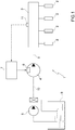
- number 1 indicates, as a whole, a common-rail, fuel direct injection system, in particular using gasoline as a fuel, for an internal combustion engine ICE.
- the direct injection system 1 comprises a plurality of injectors 2, a common rail 3, which feeds pressurized fuel to the injectors 2, a high pressure pump 4, which feeds fuel to the common rail 3 by means of a feeding duct 5 and is provided with a flow-rate adjusting device 6, a control unit 7, which causes the fuel pressure inside the common rail 3 to be equal to a desired value, which generally varies in time as a function of the engine operating conditions, and a low-pressure pump 8, which feeds fuel from a tank 9 to the high pressure pump 4 by means of a feeding duct 10.
- the control unit 7 is coupled to the flow-rate adjusting device 6 so as to control the flow-rate of the high pressure pump 4, so that the common rail 3 is supplied, instant by instant, with the amount of fuel necessary to have the desired pressure value in the common rail 3; in particular, the control unit 7 regulates the flow-rate of the high pressure pump 4 by means of a feedback control, which uses, as a feedback variable, the value of the fuel pressure inside the common rail 3, the value of the pressure being detected, in real time, by a pressure sensor 11.
- the high pressure pump 4 comprises a main body 12, which has a longitudinal axis 13 and defines, on the inside, a cylindrical pumping chamber 14.
- a piston 15 is mounted and slides inside the pumping chamber 14, and, as it slides back and forth along the longitudinal axis 13 due to the action of the lobes 16 of a camshaft 16*, it determines a cyclical change in the volume of the pumping chamber 14.
- a lower portion of the piston 15 is coupled to a spring (not shown), which, on one side, pushes the piston 15 towards a position producing a maximum volume of the pumping chamber 14, and, on the other side, is coupled to the camshaft 16*, which is caused to rotate by a drive shaft (not shown) of the engine so as to cyclically to move the piston 15 upwards compressing the spring 16.
- An intake channel 17 originates from a lateral wall of the pumping chamber 14, said intake channel 17 being connected to the low-pressure pump 8 by means of the feeding duct 10 and being regulated by an intake valve 18, which is arranged in the area of the pumping chamber 14.
- the intake valve 18 is normally pressure-controlled and, in the absence of external intervention, is closed when the fuel pressure in the pumping chamber 14 is higher than the fuel pressure in the intake channel 17, and is open when the fuel pressure in the pumping chamber 14 is lower than the fuel pressure in intake channel 17.
- a delivery channel 19 originates from a lateral wall of the pumping chamber 14 on the opposite side relative to the intake channel 17, said delivery channel 19 being connected to the common rail 3 by means of the feeding duct 5 and being regulated by a one-way delivery valve 20, which is arranged in the area of the pumping chamber 14 and only allows fuel to flow out of the pumping chamber 14.
- the delivery valve 20 is normally pressure-controlled and is open when the fuel pressure in the pumping chamber 14 is higher than the fuel pressure in delivery channel 19, and is closed when the fuel pressure in the pumping chamber 14 is lower than the fuel pressure in delivery channel 19.
- the flow-rate adjusting device 6 is mechanically coupled to the intake valve 18 so as to allow the control unit 7, when necessary, to keep the intake valve 18 open during a reflux phase RP of the piston 15, thus allowing the fuel to flow out of the pumping chamber 14 through the intake channel 17 (as we will better explain below).
- the flow-rate adjusting device 6 comprises a control rod 21, which is coupled to the intake valve 18 and is movable between a passive position, in which it allows the intake valve 18 to close and the hydraulic communication between the pumping chamber 14 and the intake channel 17 is cut off, and an active position, in which it does not allow the intake valve to close and the hydraulic communication between the pumping chamber 14 and the intake channel 17 is enabled.
- the flow-rate adjusting device 6 comprises, furthermore, an electromagnetic actuator 22, which is coupled to the control rod 21 so as to move it between the active position and the passive position.
- the electromagnetic actuator 22 comprises a spring 23, which holds the control rod 21 in the active position, and an electromagnet 24, which is controlled by the control unit 7 and is designed to move the control rod 21 to the passive position by magnetically attracting a ferromagnetic anchor 25, which is integral to the control rod 21.
- the electromagnet 24 comprises a fixed magnetic armature 26 (or magnetic bottom), which is surrounded by a coil; when an electric current flows through it, the coil generates a magnetic field that magnetically attracts the anchor 25 towards the magnetic armature 26.
- the control rod 21 and the anchor 25 form, together, a movable equipment of the flow-rate adjusting device 6, which axially moves between the active position and the passive position, always controlled by the electromagnetic actuator 22.
- the magnetic armature 26 preferably has an annular shape with a central hole, so as to have a central empty space that can house the spring 23.
- the electromagnetic actuator 22 comprises a one-way hydraulic brake, which is integral to the control rod 21 and is designed to slow down the movement of the movable equipment (i.e. of the control rod 21 and of the anchor 25) only when the movable equipment moves towards the active position (namely, the hydraulic brake does not slow down the movement of the movable equipment when the movable equipment moves towards the passive position).
- the electromagnetic actuator 22 is controlled by the control unit 7 and is powered with an electric current curve that is substantially synchronous with the top dead centre of the high pressure pump 4.
- the control unit 7 transmits electric current pulses, whose duration can vary depending on the operating point of the internal combustion engine, namely of its speed, whereas the timing of said electric current pulses can vary depending on the fuel flow-rate flowing out of the pumping chamber 14.
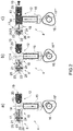
- the operating cycle of the high pressure pump 4 substantially comprises three phases.
- the operating cycle of the high pressure pump 4 is identified by each one of the lobes 16 of the camshaft 16*, which determines a cyclical change in the volume of the pumping chamber 14.
- An intake phase (shown in figure 2a ), which begins in the area of the top dead centre PTDC of the high pressure pump 4.
- the piston 15 moves downwards along the longitudinal axis 13, the intake valve 18 is open and the control rod 21 is in the active position, so as to allow fuel to flow into the pumping chamber 14 through the intake channel 17.
- a reflux phase (shown in figure 2b ) follows the intake phase SP of the high pressure pump 4 and starts in the area of the bottom dead centre PTDC of the high pressure pump 4.
- the piston 15 moves upwards along the longitudinal axis 13, the intake valve 18 is kept open and the control rod 21 is in the active position. In this way, the fuel flowing out of the pumping chamber 14 flows through the intake channel 17 and towards the low-pressure circuit.
- a pumping phase (shown in figure 2c ) follows the reflux phase of the high pressure pump 4.
- the pumping phase of the high pressure pump 4 begins in the area of the command of the control unit 7 that powers the electromagnetic actuator 22 with an electric current pulse.
- the intake valve 18 is closed due to the reflux of the fuel that flows out of the pumping chamber 14 through the intake channel 17 and towards the low-pressure circuit.
- the fuel pressure inside the pumping chamber 14 reaches a value that is such as to cause the opening of the one-way delivery valve 20, which is arranged in the area of the pumping chamber 14 and allows fuel to flow out of the pumping chamber 14.
- the opening of the one-way delivery valve 20 takes place when the fuel pressure inside the pumping chamber 14 is higher than the fuel pressure in the delivery channel 19.
- the movable equipment namely, the control rod 21 and the anchor 25
- the movement towards the passive position has a substantial effect on the operation of the high pressure pump 4 and, therefore, must be as quick as possible, so as to facilitate and improve control. Since the kinetic energy of the movable equipment at the moment of the impact against the magnetic armature 26 is a function of the square of the speed, this kinetic energy is substantially great.
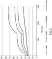
- the diagram shown in figure 3 shows the variation in time of the temperature detected in the area of four points of the high pressure pump 4. More in detail, INLET indicates the variation in time of the temperature measured in the area of the intake channel 10, OUTLET indicates the variation in time of the temperature measured in the area of the delivery channel 19, DAMPER indicates the variation in time of the temperature measured in the area of the channel 17, whereas FIXTURE indicates the variation in time of the temperature measured in the area of a support 27 of the high pressure pump 4.
- the four developments of the temperature detected in the area of the different points of the high pressure pump 4 are substantially similar and have two sharp variations in the area of a pressure increase ⁇ p from 200 to 600 bar and in the area of a pressure increase ⁇ p from 600 to 800 bar.
- the temperature variation ⁇ T ranges from 30 to 50 °C in the area of the different points of the high pressure pump 4.
- the temperature variation ⁇ T assumes greater values in the range of 80°C. While a temperature variation ⁇ T ranging from 30 to 50 °C could lead to cavitation problems for the high pressure pump 4, in case of a temperature variation ⁇ T in the range of 80°C the high pressure pump becomes definitely unstable and scarcely reliable.
- the heat generated during the pumping phase is drained through the fuel flow rate flowing out of the high pressure pump 4.
- control unit 7 is designed to control the high pressure pump 4 so as to contain the temperature variation ⁇ T generated during the pumping phase in the high pressure pump 4.
- control unit 7 in order to control the high pressure pump 4 so as to contain the temperature variation ⁇ T generated during the pumping phase in the high pressure pump 4.
- the strategy involve calculating the objective fuel flow rate M ref to be fed by the high pressure pump 4 to the common rail 3 instant by instant to have the desired pressure value inside the common rail 3.
- control unit 7 is designed to compare the objective fuel flow rate M ref with the maximum flow rate M max that can be delivered by the high pressure pump 4.
- the difference between the objective fuel flow rate M ref and the maximum flow rate M max that can be delivered by the high pressure pump is irrelevant (or, anyway, lower than a threshold value TV that can be adjusted during a set up phase of the control unit 7)
- no strategy is implemented in order to control the high pressure pump 4 so as to contain the temperature variation ⁇ T generated during the pumping phase in the high pressure pump 4.
- the control unit 7 is designed to adjust the flow rate of the high pressure pump 4 so as to process the maximum flow rate M max that can be delivered by the high pressure pump 4.
- the control unit 7 is designed to control the alternation of operating cycles, in which the high pressure pump 4 processes the maximum flow rate M max that can be delivered by the high pressure pump 4, and idle operating cycles.
- control unit 7 is designed to control exclusively the alternation of two operating cycles: operation cycles in which the high pressure pump 4 processes the maximum flow rate M max that can be delivered by the high pressure pump 4, and idle operating cycles.
- control unit 7 is designed to carry out an operating cycle of the high pressure pump 4 with the maximum flow rate M max that can be delivered by the high pressure pump 4 and the idle operating cycle of the high pressure pump 4.
- the high pressure pump 4 can process the same fuel flow rate in the two operating cycles (equal to the maximum flow rate M max that can be delivered by the high pressure pump 4), but the heat generated during the idle operating cycle of the high pressure pump 4 is drained by the fuel flow rate flowing out of the high pressure pump 4 in the operating cycle of the high pressure pump 4 with the maximum flow rate M max that can be delivered.
- the control unit 7 is designed to carry out an operating cycle of the high pressure pump 4 with the maximum flow rate M max that can be delivered by the high pressure pump 4 every n operating cycles of the high pressure pump 4, whereas the remaining (n - 1) operating cycles will be idle operating cycles of the high pressure pump 4.
- the control unit 7 is designed to control the high pressure pump 4 by means of a feedback control, which uses, as feedback variables, the value of the fuel pressure inside the common rail 3, preferably detected in real time by a pressure sensor 11, and the comparison between the maximum flow rate M max that can be delivered by the high pressure pump 4 and the objective fuel flow rate M ref to be fed by the high pressure pump 4 to the common rail 3 instant by instant to have the desired pressure value inside the common rail 3.
- a feedback control which uses, as feedback variables, the value of the fuel pressure inside the common rail 3, preferably detected in real time by a pressure sensor 11, and the comparison between the maximum flow rate M max that can be delivered by the high pressure pump 4 and the objective fuel flow rate M ref to be fed by the high pressure pump 4 to the common rail 3 instant by instant to have the desired pressure value inside the common rail 3.
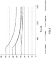
- the diagram shown in figure 4 shows the variation in time of the temperature detected in the area of four points of the high pressure pump 4 implementing the control strategy of the high pressure pump 4 described above. More in detail, INLET indicates the variation in time of the temperature measured in the area of the intake channel 10, OUTLET indicates the variation in time of the temperature measured in the area of the delivery channel 19, DAMPER indicates the variation in time of the temperature measured in the area of the channel 17, whereas FIXTURE indicates the variation in time of the temperature measured in the area of the support 27 of the high pressure pump 4.
- the four developments of the temperature detected in the area of the different points of the high pressure pump 4 are substantially similar and have two slight variations in the area of a pressure increase ⁇ p from 200 to 600 bar and in the area of a pressure increase ⁇ p from 600 to 800 bar.
- the temperature variation ⁇ T ranges from 30 to 40 °C in the area of the different points of the high pressure pump 4.
- the temperature variation ⁇ T assumes higher values that, anyway, are lower than 50°C.
- the strategy implemented by the control unit 7 to control the high pressure pump 4 and described so far has some advantages. In particular, despite being advantageous in terms of costs, it is also easy and cheap to be implemented. In particular, the method described above does not involve an excessive computing burden for the control unit 7, permitting at the same time a limitation of the temperature variation ⁇ T generated during the pumping phase in the high pressure pump 4 and maintaining the fuel pressure objective value inside the common rail 3.
Applications Claiming Priority (1)
| Application Number | Priority Date | Filing Date | Title |
|---|---|---|---|
| ITUA2016A003392A ITUA20163392A1 (it) | 2016-05-12 | 2016-05-12 | Metodo di controllo di una pompa carburante per un sistema di iniezione diretta |
Publications (2)
| Publication Number | Publication Date |
|---|---|
| EP3244047A1 true EP3244047A1 (de) | 2017-11-15 |
| EP3244047B1 EP3244047B1 (de) | 2024-02-14 |
Family
ID=56894154
Family Applications (1)
| Application Number | Title | Priority Date | Filing Date |
|---|---|---|---|
| EP17170405.9A Active EP3244047B1 (de) | 2016-05-12 | 2017-05-10 | Verfahren zur steuerung einer kraftstoffpumpe für ein direkteinspritzsystem |
Country Status (5)
| Country | Link |
|---|---|
| US (1) | US10113498B2 (de) |
| EP (1) | EP3244047B1 (de) |
| JP (1) | JP6940298B2 (de) |
| CN (1) | CN107366585B (de) |
| IT (1) | ITUA20163392A1 (de) |
Cited By (1)
| Publication number | Priority date | Publication date | Assignee | Title |
|---|---|---|---|---|
| IT201900012300A1 (it) * | 2019-07-18 | 2021-01-18 | Magneti Marelli Spa | Metodo per controllare una pompa carburante ad alta pressione per un sistema di iniezione diretta |
Families Citing this family (3)
| Publication number | Priority date | Publication date | Assignee | Title |
|---|---|---|---|---|
| DE102016204408A1 (de) * | 2016-03-17 | 2017-09-21 | Robert Bosch Gmbh | Verfahren zum Ermitteln eines Sollwertes für eine Stellgröße zur Ansteuerung einer Niederdruckpumpe |
| JP6973010B2 (ja) * | 2017-12-13 | 2021-11-24 | トヨタ自動車株式会社 | 燃料ポンプの制御装置 |
| JP6922713B2 (ja) * | 2017-12-13 | 2021-08-18 | トヨタ自動車株式会社 | 燃料ポンプの制御装置 |
Citations (4)
| Publication number | Priority date | Publication date | Assignee | Title |
|---|---|---|---|---|
| EP1195514A2 (de) * | 2000-10-03 | 2002-04-10 | C.R.F. Società Consortile per Azioni | Vorrichtung zur Regelung des Durchflusses einer Hochdruckpumpe in einem Common-rail Kraftstoffeinspritzsystem einer Brennkraftmaschine |
| EP2011997A1 (de) * | 2007-07-05 | 2009-01-07 | MAGNETI MARELLI POWERTRAIN S.p.A. | Verfahren zur Steuerung eines Überdruckventils in einem Common-Rail-Kraftstoffversorgungssystem |
| EP2039920A1 (de) | 2007-09-21 | 2009-03-25 | MAGNETI MARELLI POWERTRAIN S.p.A. | Steuerverfahren für ein direktes Einspritzsystem für öffentliche Kraftstoffleitungen mit einem Absperrventil zur Steuerung des Flusses einer Hochdruckbrennstoffpumpe |
| EP2508744A1 (de) * | 2011-04-07 | 2012-10-10 | Magneti Marelli S.p.A. | Schallgedämpfte Kraftstoffpumpe für ein Direkteinspritzsystem |
Family Cites Families (17)
| Publication number | Priority date | Publication date | Assignee | Title |
|---|---|---|---|---|
| DE19810867C2 (de) * | 1998-03-13 | 2000-02-24 | Bosch Gmbh Robert | Kraftstoffpumpen-Anordnung |
| JP4627603B2 (ja) * | 2001-03-15 | 2011-02-09 | 日立オートモティブシステムズ株式会社 | 燃料供給装置 |
| JP4123729B2 (ja) * | 2001-03-15 | 2008-07-23 | 株式会社日立製作所 | 燃料供給装置の制御方法 |
| DE10115324A1 (de) * | 2001-03-28 | 2002-10-17 | Bosch Gmbh Robert | Kraftstoffsystem |
| ITBO20020498A1 (it) * | 2002-07-30 | 2004-01-30 | Magneti Marelli Powertrain Spa | Impianto di iniezione di carburante di tipo common rail con pompa a portata variabile |
| ITBO20040322A1 (it) * | 2004-05-20 | 2004-08-20 | Magneti Marelli Powertrain Spa | Metodo ed impianto per l'iniezione diretta di carburante in un motore a combustione interna |
| JP4438553B2 (ja) * | 2004-07-30 | 2010-03-24 | トヨタ自動車株式会社 | 内燃機関の高圧燃料系統の制御装置 |
| DE102005014093A1 (de) * | 2005-03-29 | 2006-10-05 | Robert Bosch Gmbh | Zweipunktregelung einer Hochdruckpumpe für direkteinspritzende Ottomotoren |
| CA2505455C (en) * | 2005-05-18 | 2007-02-20 | Westport Research Inc. | Direct injection gaseous fuelled engine and method of controlling fuel injection pressure |
| JP4050287B2 (ja) * | 2005-08-10 | 2008-02-20 | 三菱電機株式会社 | 内燃機関の省エネ方式の高圧燃料供給制御装置 |
| US8015964B2 (en) * | 2006-10-26 | 2011-09-13 | David Norman Eddy | Selective displacement control of multi-plunger fuel pump |
| DE102007021327A1 (de) * | 2007-05-07 | 2008-11-13 | Robert Bosch Gmbh | Kraftstoffeinspritzsystem mit Druckverstärkung |
| US7677872B2 (en) * | 2007-09-07 | 2010-03-16 | Gm Global Technology Operations, Inc. | Low back-flow pulsation fuel injection pump |
| US7827967B2 (en) * | 2008-10-23 | 2010-11-09 | Gm Global Technology Operations, Inc. | Low noise fuel pump with variable pressure regulation |
| IT1398227B1 (it) * | 2009-06-09 | 2013-02-22 | Magneti Marelli Spa | Metodo per l'auto apprendimento della variazione di una caratteristica di funzionamento nominale di una pompa ad alta pressione a portata variabile in un motore a combustione interna |
| DE102009031529B3 (de) * | 2009-07-02 | 2010-11-11 | Mtu Friedrichshafen Gmbh | Verfahren zur Steuerung und Regelung einer Brennkraftmaschine |
| US9353699B2 (en) * | 2014-03-31 | 2016-05-31 | Ford Global Technologies, Llc | Rapid zero flow lubrication methods for a high pressure pump |
-
2016
- 2016-05-12 IT ITUA2016A003392A patent/ITUA20163392A1/it unknown
-
2017
- 2017-05-10 EP EP17170405.9A patent/EP3244047B1/de active Active
- 2017-05-11 US US15/592,420 patent/US10113498B2/en active Active
- 2017-05-12 JP JP2017095312A patent/JP6940298B2/ja active Active
- 2017-05-12 CN CN201710334708.4A patent/CN107366585B/zh active Active
Patent Citations (4)
| Publication number | Priority date | Publication date | Assignee | Title |
|---|---|---|---|---|
| EP1195514A2 (de) * | 2000-10-03 | 2002-04-10 | C.R.F. Società Consortile per Azioni | Vorrichtung zur Regelung des Durchflusses einer Hochdruckpumpe in einem Common-rail Kraftstoffeinspritzsystem einer Brennkraftmaschine |
| EP2011997A1 (de) * | 2007-07-05 | 2009-01-07 | MAGNETI MARELLI POWERTRAIN S.p.A. | Verfahren zur Steuerung eines Überdruckventils in einem Common-Rail-Kraftstoffversorgungssystem |
| EP2039920A1 (de) | 2007-09-21 | 2009-03-25 | MAGNETI MARELLI POWERTRAIN S.p.A. | Steuerverfahren für ein direktes Einspritzsystem für öffentliche Kraftstoffleitungen mit einem Absperrventil zur Steuerung des Flusses einer Hochdruckbrennstoffpumpe |
| EP2508744A1 (de) * | 2011-04-07 | 2012-10-10 | Magneti Marelli S.p.A. | Schallgedämpfte Kraftstoffpumpe für ein Direkteinspritzsystem |
Cited By (3)
| Publication number | Priority date | Publication date | Assignee | Title |
|---|---|---|---|---|
| IT201900012300A1 (it) * | 2019-07-18 | 2021-01-18 | Magneti Marelli Spa | Metodo per controllare una pompa carburante ad alta pressione per un sistema di iniezione diretta |
| EP3767099A1 (de) * | 2019-07-18 | 2021-01-20 | Marelli Europe S.p.A. | Verfahren zur steuerung einer kraftstoffhochdruckpumpe für ein direkteinspritzsystem |
| US11041447B2 (en) | 2019-07-18 | 2021-06-22 | Marelli Europe S.P.A. | Method to control a high-pressure fuel pump for a direct injection system |
Also Published As
| Publication number | Publication date |
|---|---|
| EP3244047B1 (de) | 2024-02-14 |
| CN107366585A (zh) | 2017-11-21 |
| US20170328295A1 (en) | 2017-11-16 |
| JP2018021541A (ja) | 2018-02-08 |
| JP6940298B2 (ja) | 2021-09-22 |
| ITUA20163392A1 (it) | 2017-11-12 |
| CN107366585B (zh) | 2021-09-24 |
| US10113498B2 (en) | 2018-10-30 |
Similar Documents
| Publication | Publication Date | Title |
|---|---|---|
| EP3244047B1 (de) | Verfahren zur steuerung einer kraftstoffpumpe für ein direkteinspritzsystem | |
| US8418677B2 (en) | High pressure fuel pump control system for internal combustion engine | |
| EP2453122B1 (de) | Verfahren und Steuergerät zur Steuerung einer Hochdruckkraftstoffförderpumpe zur Speisung von Kraftstoff unter Druck in einen Verbrennungsmotor | |
| US6701898B2 (en) | Fuel supply apparatus and method of control thereof | |
| EP1598548B1 (de) | Verfahren und Vorrichtung zur Kraftstoffdirekteinspritzung in eine Brennkraftmaschine | |
| EP1598549B1 (de) | Verfahren zur Kraftstoffdirekteinspritzung in eine Brennkraftmaschine | |
| EP1965069A2 (de) | Steuerventil für ein Direkteinspritzungs-Gas-Brennstoff-System | |
| KR101603643B1 (ko) | 고압연료펌프용 유량제어밸브의 제어장치 및 제어방법 | |
| RU2015150298A (ru) | Способ (варианты) и система для впрыска топлива при постоянном и переменном давлении | |
| RU2681554C2 (ru) | Способ для топливной системы и топливная система (варианты) | |
| JP2003214301A (ja) | 内燃機関を動作させるための方法、コンピュータプログラムおよび開ループおよび/または閉ループ制御装置、並びに内燃機関 | |
| CN113494400A (zh) | 用于直接喷射燃料泵控制的系统和方法 | |
| JP5085483B2 (ja) | エンジンの高圧燃料ポンプ制御装置 | |
| EP0552899A1 (de) | Pumpendüse | |
| JP2006002661A (ja) | 排気弁駆動制御方法及び装置 | |
| JP2004156574A (ja) | コモンレール(cr)燃料噴射システムの作動油損失・油圧変動低減構造 | |
| JP2003269287A (ja) | 高圧燃料供給システム | |
| JP5881505B2 (ja) | 油圧駆動燃料噴射装置 | |
| CN213039381U (zh) | 一种发动机电控燃油喷射系统 | |
| RU77358U1 (ru) | Система топливоподачи дизеля с управляемым начальным давлением | |
| EP1717439B9 (de) | Brennstoffeinspritzsystem für Brennkraftmaschine | |
| GB2550391A (en) | Method to control self-latching of high pressure piston driven fuel pumps |
Legal Events
| Date | Code | Title | Description |
|---|---|---|---|
| PUAI | Public reference made under article 153(3) epc to a published international application that has entered the european phase |
Free format text: ORIGINAL CODE: 0009012 |
|
| STAA | Information on the status of an ep patent application or granted ep patent |
Free format text: STATUS: THE APPLICATION HAS BEEN PUBLISHED |
|
| AK | Designated contracting states |
Kind code of ref document: A1 Designated state(s): AL AT BE BG CH CY CZ DE DK EE ES FI FR GB GR HR HU IE IS IT LI LT LU LV MC MK MT NL NO PL PT RO RS SE SI SK SM TR |
|
| AX | Request for extension of the european patent |
Extension state: BA ME |
|
| STAA | Information on the status of an ep patent application or granted ep patent |
Free format text: STATUS: REQUEST FOR EXAMINATION WAS MADE |
|
| 17P | Request for examination filed |
Effective date: 20180514 |
|
| STAA | Information on the status of an ep patent application or granted ep patent |
Free format text: STATUS: EXAMINATION IS IN PROGRESS |
|
| 17Q | First examination report despatched |
Effective date: 20210601 |
|
| STAA | Information on the status of an ep patent application or granted ep patent |
Free format text: STATUS: EXAMINATION IS IN PROGRESS |
|
| RAP3 | Party data changed (applicant data changed or rights of an application transferred) |
Owner name: MARELLI EUROPE S.P.A. |
|
| GRAP | Despatch of communication of intention to grant a patent |
Free format text: ORIGINAL CODE: EPIDOSNIGR1 |
|
| STAA | Information on the status of an ep patent application or granted ep patent |
Free format text: STATUS: GRANT OF PATENT IS INTENDED |
|
| RIC1 | Information provided on ipc code assigned before grant |
Ipc: F02D 41/38 20060101AFI20230731BHEP |
|
| INTG | Intention to grant announced |
Effective date: 20230904 |
|
| P01 | Opt-out of the competence of the unified patent court (upc) registered |
Effective date: 20231011 |
|
| GRAS | Grant fee paid |
Free format text: ORIGINAL CODE: EPIDOSNIGR3 |
|
| GRAA | (expected) grant |
Free format text: ORIGINAL CODE: 0009210 |
|
| STAA | Information on the status of an ep patent application or granted ep patent |
Free format text: STATUS: THE PATENT HAS BEEN GRANTED |
|
| AK | Designated contracting states |
Kind code of ref document: B1 Designated state(s): AL AT BE BG CH CY CZ DE DK EE ES FI FR GB GR HR HU IE IS IT LI LT LU LV MC MK MT NL NO PL PT RO RS SE SI SK SM TR |
|
| REG | Reference to a national code |
Ref country code: GB Ref legal event code: FG4D |
|
| REG | Reference to a national code |
Ref country code: CH Ref legal event code: EP |
|
| REG | Reference to a national code |
Ref country code: DE Ref legal event code: R096 Ref document number: 602017079096 Country of ref document: DE |
|
| REG | Reference to a national code |
Ref country code: IE Ref legal event code: FG4D |