EP3243987A1 - Zur befestigung in einer eine hinterschneidung aufweisenden beschlagnut vorgesehenes beschlagteil - Google Patents
Zur befestigung in einer eine hinterschneidung aufweisenden beschlagnut vorgesehenes beschlagteil Download PDFInfo
- Publication number
- EP3243987A1 EP3243987A1 EP17168169.5A EP17168169A EP3243987A1 EP 3243987 A1 EP3243987 A1 EP 3243987A1 EP 17168169 A EP17168169 A EP 17168169A EP 3243987 A1 EP3243987 A1 EP 3243987A1
- Authority
- EP
- European Patent Office
- Prior art keywords
- base plate
- fitting
- holding element
- undercut
- fitting part
- Prior art date
- Legal status (The legal status is an assumption and is not a legal conclusion. Google has not performed a legal analysis and makes no representation as to the accuracy of the status listed.)
- Granted
Links
Images
Classifications
-
- E—FIXED CONSTRUCTIONS
- E05—LOCKS; KEYS; WINDOW OR DOOR FITTINGS; SAFES
- E05D—HINGES OR SUSPENSION DEVICES FOR DOORS, WINDOWS OR WINGS
- E05D5/00—Construction of single parts, e.g. the parts for attachment
- E05D5/02—Parts for attachment, e.g. flaps
- E05D5/0215—Parts for attachment, e.g. flaps for attachment to profile members or the like
- E05D5/0223—Parts for attachment, e.g. flaps for attachment to profile members or the like with parts, e.g. screws, extending through the profile wall or engaging profile grooves
- E05D5/0238—Parts for attachment, e.g. flaps for attachment to profile members or the like with parts, e.g. screws, extending through the profile wall or engaging profile grooves with parts engaging profile grooves
-
- E—FIXED CONSTRUCTIONS
- E05—LOCKS; KEYS; WINDOW OR DOOR FITTINGS; SAFES
- E05B—LOCKS; ACCESSORIES THEREFOR; HANDCUFFS
- E05B9/00—Lock casings or latch-mechanism casings ; Fastening locks or fasteners or parts thereof to the wing
- E05B9/08—Fastening locks or fasteners or parts thereof, e.g. the casings of latch-bolt locks or cylinder locks to the wing
-
- E—FIXED CONSTRUCTIONS
- E05—LOCKS; KEYS; WINDOW OR DOOR FITTINGS; SAFES
- E05C—BOLTS OR FASTENING DEVICES FOR WINGS, SPECIALLY FOR DOORS OR WINDOWS
- E05C9/00—Arrangements of simultaneously actuated bolts or other securing devices at well-separated positions on the same wing
Definitions
- the invention relates to an arrangement provided in an undercut having a fitting groove provided fitting part of a drive rod fitting for a window or the like with a base plate and a base plate connected to the holding element, wherein the holding element relative to the base plate of a mounting position in which the holding element in the fitting to can be moved behind the undercut, in an operating position in which the holding element engages behind the undercut to a bearing point is rotatable.
- a displaceably held in the fitting groove fitting part is from the EP 2 546 438 A2 known.
- this fitting part forms a part of a locking pin of the espagnolette fitting the bearing point.
- An eccentric connecting the retaining element to the base plate allows the components to rotate relative to each other.
- such an eccentric is very expensive.
- the eccentric must be reliably secured against twisting.
- the invention is based on the problem, a fitting part of the type mentioned so on to form that it is particularly inexpensive to manufacture.
- a compound of the base plate with the holding element guided in a slot Clamping element has that the clamping element biases the holding element in the direction of the base plate and that the slot is aligned in the direction of rotation of the holding element.
- the holding element and the base plate of the clamping element are biased against each other. This avoids the use of expensive eccentrics.
- the fitting part is thus particularly cost-effective. About the dimensions of the slot and the use of possible spacers between the support member and the base plate can determine whether the fitting is held immovably or displaceably in the fitting.
- the rotation of the holding element behind the undercut of the fitting groove is carried out automatically during assembly of the clamping element when the slot is inclined in an the clamping element supporting portion to one end.
- the clamping element, the holding element as long to rotate about the bearing point until it reaches the lowest point in the inclined portion or abuts the retaining element on a wall of the fitting groove.
- the inclined portion of the slot has a chamfer and the clamping element has a countersunk screw.
- the holding element rotates independently relative to the base plate when tightening the countersunk screw.
- connection of the base plate with the holding element designed according to another advantageous embodiment of the invention structurally particularly simple when the bearing has a screwed into the retaining element screw.
- the fitting part has, according to another advantageous embodiment of the invention, a particularly high stability, when the base plate is screwed together with the holding element at the bearing point and on the slot.
- the fitting part is reliably secured according to another advantageous embodiment of the invention in the fitting groove against displacement when the holding element of the base plate facing, provided for support in the undercut of the fitting groove claws. During assembly of the clamping element, the claws reach against the undercut of the fitting groove.
- An intended positioning of the retaining element in the fitting groove is particularly simple according to another advantageous development of the invention, when the retaining element of the base plate has facing projections and when the projections are narrower than the width of the fitting groove on the undercut. These projections are most easily formed as stampings of the holding element. The projections can be supported on the base plate and prevent its jamming at a slidable mounting of the fitting and limit the maximum possible rotation of the retaining element in the fitting.
- a rotation of the base plate in a rotation of the retaining element can be reliably avoided according to another advantageous embodiment of the invention, when the base plate has support edges for lateral support on walls of the fitting groove.
- the base plate may have the width of the fitting groove above the undercut and inserted into the fitting groove.
- the base plate may also have in the fitting groove projecting bends or stampings.
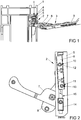
- FIG. 1 The fitting 2 is held immovably in a fitting groove 4 of the frame 1 and has a base plate 5 and a holding element 6.
- a scissors bearing 3 is usually used as the upper bearing for one designed as a turn-tilt fitting and concealed in the window arranged espagnolette fitting and has two bearing arms 7, 8 for supporting a scissor arm 9.
- One of the bearing arms 8 is immovably mounted in the base plate 5, while the other of the bearing arms 7 slidable in the base plate 5 is stored.
- FIG. 2 shows the fitting part 2 in a view from position II FIG. 1 , It can be seen that the holding element 6 is rotated relative to the base plate 5.
- the connection of the holding element 6 with the base plate 5 has a bearing 10 and a remote from the bearing 10 clamping element 11.
- the bearing 10 and the clamping element 11 each have in the retaining element 6 screwed screws 12, 13.
- To simplify the drawing of the scissor arm 9 is off FIG. 1 in FIG. 3 not shown.
- the displaceably mounted in the base plate bearing arm 7 is mounted in a sliding block 14.
- the sliding block 14 is guided in a slot 15 of the base plate 5.
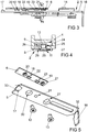
- FIG. 3 shows a side view of the fitting part 2 FIG. 1 ,
- the base plate 5 has two angled portions 16, 17, which protrude into the fitting groove 4. Due to the angled portions 16, 17, the base plate 5 is held non-rotatably in the fitting groove 4. Projections 18, 19, supporting edges 20, 21 and claws 21, 22 of the holding element 6 are facing the base plate 5.
- the fitting part 2 in the region of the clamping element 11 is in FIG. 4 in a sectional view taken along the line IV - IV FIG. 3 shown.
- FIG. 4 schematically the fitting groove 4 shown.
- the holding element 6 is biased against the base plate 5. Retaining element 5 and base plate 6 thus clamp the undercut 24 forming webs 25, 26 of the fitting groove 4 a.
- the holding element 5 is thereby held behind the undercut 24 of the fitting groove 4 forming webs 25, 26, while the base plate 5 is supported on the other side of the webs 25, 26 on the frame 1.
- the holding element 6 has a width with which it can be inserted in a substantially parallel orientation to the base plate 5 between the webs 25, 26 in the fitting groove 4.
- the screw 13 of the clamping element 11 is guided through a slot 27 in the base plate 4.
- the slot 27 is aligned in the direction of rotation of the holding element 6, such that the holding element 6 is rotatable about the bearing 10.
- the slot 27 has a chamfer 28 with an end inclined toward a portion 29 for supporting the screw 13 of the clamping element 11.
- the holding element 6 rotates until the screw 13 to the limit of the slot 27 and the retaining element 6 abuts against the boundary of the fitting groove 4 or the undercut 24 of the fitting groove 4 is clamped between the retaining element 6 and the base plate 5.
- the screws 12, 13 are each formed as countersunk screws.
- FIG. 5 shows the fitting part 2 in an exploded view.
- the base plate 5 has a screw hole 30 for the screw 12 of the bearing 10 and the slot 27 for the screw 13 of the clamping element 11.
- the base plate 5 also has a bearing bore 31 for supporting the non-displaceable bearing arm 8 from the Figures 1 and 2 ,
- the bends of the base plate have support edges for support in the fitting groove.
Landscapes
- Engineering & Computer Science (AREA)
- Mechanical Engineering (AREA)
- Connection Of Plates (AREA)
- Hinges (AREA)
Abstract
Description
- Die Erfindung betrifft ein zur Anordnung in einer eine Hinterschneidung aufweisenden Beschlagnut vorgesehenes Beschlagteil eines Treibstangenbeschlages für ein Fenster oder dergleichen mit einer Grundplatte und einem mit der Grundplatte verbundenen Halteelement, wobei das Halteelement gegenüber der Grundplatte von einer Montagestellung, in der das Halteelement in die Beschlagnut bis hinter die Hinterschneidung bewegbar ist, in eine Betriebsstellung, in der das Halteelement die Hinterschneidung hintergreift, um eine Lagerstelle verdrehbar ist.
- Ein verschieblich in der Beschlagnut gehaltenes Beschlagteil ist aus der
EP 2 546 438 A2 bekannt. Bei diesem Beschlagteil bildet ein Teil eines Schließzapfens des Treibstangenbeschlages die Lagerstelle. Ein das Halteelement mit der Grundplatte verbindender Exzenter ermöglicht die Verdrehung der Bauteile zueinander. Ein solcher Exzenter ist jedoch sehr kostenintensiv. Zudem muss der Exzenter zuverlässig gegen ein Verdrehen gesichert werden. - Weiterhin ist aus der
DE 10 2011 080 795 B3 eine Befestigungsanordnung zur unverschieblichen Befestigung eines Bauteils in einer Beschlagnut bekannt geworden, bei dem zwei exzenterförmige Klemmelemente ein Klemmstück gegen eine Wandung der Beschlagnut vorspannen. Die exzenterförmigen Klemmelemente und das Klemmstück sind jedoch sehr kostenintensive Bauteile. - Der Erfindung liegt das Problem zugrunde, ein Beschlagteil der eingangs genannten Art so weiter zu bilden, dass es besonders kostengünstig zu fertigen ist.
- Dieses Problem wird erfindungsgemäß dadurch gelöst, dass eine Verbindung der Grundplatte mit dem Halteelement ein in einem Langloch geführtes Spannelement hat, dass das Spannelement das Halteelement in Richtung der Grundplatte vorspannt und dass das Langloch in Verdrehrichtung des Halteelementes ausgerichtet ist.
- Durch diese Gestaltung sind das Halteelement und die Grundplatte von dem Spannelement gegeneinander vorgespannt. Damit wird der Einsatz von kostenintensiven Exzentern vermieden. Das Beschlagteil gestaltet sich damit besonders kostengünstig. Über die Abmessungen des Langlochs und den Einsatz möglicher Abstandhalter zwischen dem Halteelement und der Grundplatte lässt sich festlegen, ob das Beschlagteil unverschieblich oder verschieblich in der Beschlagnut gehalten ist.
- Die Verdrehung des Halteelementes hinter der Hinterschneidung der Beschlagnut erfolgt bei der Montage des Spannelementes selbständig, wenn das Langloch in einem das Spannelement abstützenden Abschnitt zu einem Ende hin geneigt ist. Durch diese Gestaltung wird das Spannelement das Halteelement so lange um die Lagerstelle verdrehen, bis es an die tiefste Stelle in dem geneigten Abschnitt gelangt oder das Halteelement an einer Wandung der Beschlagnut anstößt.
- Zur Vereinfachung der Montage des Beschlagteils trägt es gemäß einer anderen vorteilhaften Weiterbildung der Erfindung bei, wenn das Spannelement eine in dem Halteelement eingedrehte Schraube hat.
- Zur weiteren Vereinfachung der Montage des Beschlagteils trägt es gemäß einer anderen vorteilhaften Weiterbildung der Erfindung bei, wenn der geneigte Abschnitt des Langlochs eine Fase und das Spannelement eine Senkkopfschraube aufweist. Durch diese Gestaltung verdreht sich das Halteelement selbständig gegenüber der Grundplatte beim Anziehen der Senkkopfschraube.
- Die Verbindung der Grundplatte mit dem Halteelement gestaltet sich gemäß einer anderen vorteilhaften Weiterbildung der Erfindung konstruktiv besonders einfach, wenn die Lagerstelle eine in das Halteelement eingedrehte Schraube hat.
- Das Beschlagteil weist gemäß einer anderen vorteilhaften Weiterbildung der Erfindung eine besonders hohe Stabilität auf, wenn die Grundplatte mit dem Halteelement an der Lagerstelle und an dem Langloch miteinander verschraubt ist.
- Das Beschlagteil ist gemäß einer anderen vorteilhaften Weiterbildung der Erfindung in der Beschlagnut zuverlässig gegen ein Verschieben gesichert, wenn das Halteelement der Grundplatte zugewandte, zur Abstützung in der Hinterschneidung der Beschlagnut vorgesehene Krallen hat. Bei der Montage des Spannelementes gelangen die Krallen gegen die Hinterschneidung der Beschlagnut.
- Eine vorgesehene Positionierung des Halteelementes in der Beschlagnut gestaltet sich gemäß einer anderen vorteilhaften Weiterbildung der Erfindung besonders einfach, wenn das Halteelement der Grundplatte zugewandte Vorsprünge hat und wenn die Vorsprünge schmaler sind als die Breite der Beschlagnut an der Hinterschneidung. Diese Vorsprünge sind am einfachsten als Verprägungen des Haltelementes ausgebildet. Die Vorsprünge können sich an der Grundplatte abstützen und bei einer verschieblichen Montage des Beschlagteils dessen Verklemmen verhindern und die maximal mögliche Verdrehung des Halteelementes in der Beschlagnut begrenzen.
- Ein Verdrehen der Grundplatte bei einer Verdrehung des Halteelementes lässt sich gemäß einer anderen vorteilhaften Weiterbildung der Erfindung zuverlässig vermeiden, wenn die Grundplatte Stützränder zur seitlichen Abstützung an Wandungen der Beschlagnut hat. Hierzu kann die Grundplatte die Breite der Beschlagnut oberhalb der Hinterschneidung aufweisen und in die Beschlagnut eingesetzt werden. Alternativ dazu kann die Grundplatte auch in die Beschlagnut hineinragende Abwinklungen oder Verprägungen aufweisen.
- Die Erfindung lässt zahlreiche Ausführungsformen zu. Zur weiteren Verdeutlichung ihres Grundprinzips ist eine davon in der Zeichnung dargestellt und wird nachfolgend beschrieben. Diese zeigt in
- Fig. 1
- einen Teilbereich eines Fensters mit einem Beschlagteil für ein Scherenlager,
- Fig. 2
- das Beschlagteil aus
Figur 1 von Position II aus gesehen, - Fig. 3
- eine Seitenansicht des Beschlagteils aus
Figur 1 , - Fig. 4
- eine Schnittdarstellung entlang der Linie IV - IV aus Figur 3 mit angrenzenden Bereichen einer Beschlagnut.
- Fig. 5
- eine Explosionsdarstellung des Beschlagteils aus
Figur 1 . -
Figur 1 zeigt einen Eckbereich eines Rahmens 1 eines Fensters mit einem Beschlagteil 2 für ein Scherenlager 3. Das Beschlagteil 2 ist unverschieblich in einer Beschlagnut 4 des Rahmens 1 gehalten und hat eine Grundplatte 5 und ein Halteelement 6. Ein solches Scherenlager 3 wird meist als oberes Lager für einen als Dreh-Kipp-Beschlag ausgebildeten und verdeckt im Fenster angeordneten Treibstangenbeschlag eingesetzt und hat zwei Lagerarme 7, 8 zur Lagerung eines Scherenarms 9. Einer der Lagerarme 8 ist unverschieblich in der Grundplatte 5 gelagert, während der andere der Lagerarme 7 verschieblich in der Grundplatte 5 gelagert ist. -
Figur 2 zeigt das Beschlagteil 2 in einer Ansicht von Position II ausFigur 1 . Hierbei ist zu erkennen, dass das Halteelement 6 gegenüber der Grundplatte 5 verdreht ist. Die Verbindung des Halteelementes 6 mit der Grundplatte 5 hat eine Lagerstelle 10 und ein entfernt von der Lagerstelle 10 angeordnetes Spannelement 11. Die Lagerstelle 10 und das Spannelement 11 weisen jeweils in das Halteelement 6 eingedrehte Schrauben 12, 13 auf. Zur Vereinfachung der Zeichnung ist der Scherenarm 9 ausFigur 1 inFigur 3 nicht dargestellt. Der verschieblich in der Grundplatte gelagerte Lagerarm 7 ist in einem Kulissenstein 14 gelagert. Der Kulissenstein 14 ist in einem Langloch 15 der Grundplatte 5 geführt. -
Figur 3 zeigt eine Seitenansicht des Beschlagteils 2 ausFigur 1 . Die Grundplatte 5 weist zwei Abwinklungen 16, 17 auf, welche in die Beschlagnut 4 hineinragen. Durch die Abwinklungen 16, 17 ist die Grundplatte 5 unverdrehbar in der Beschlagnut 4 gehalten. Vorsprünge 18, 19, Stützränder 20, 21 und Krallen 21, 22 des Halteelementes 6 sind der Grundplatte 5 zugewandt. - Das Beschlagteil 2 im Bereich des Spannelementes 11 ist in
Figur 4 in einer Schnittdarstellung entlang der Linie IV - IV ausFigur 3 dargestellt. Ergänzend ist inFigur 4 schematisch die Beschlagnut 4 dargestellt. Das Halteelement 6 ist gegen die Grundplatte 5 vorgespannt. Halteelement 5 und Grundplatte 6 spannen damit die Hinterschneidung 24 bildende Stege 25, 26 der Beschlagnut 4 ein. Das Halteelement 5 ist hierdurch hinter den die Hinterschneidung 24 der Beschlagnut 4 bildenden Stegen 25, 26 gehalten, während sich die Grundplatte 5 auf der anderen Seite der Stege 25, 26 an dem Rahmen 1 abstützt. Das Haltelement 6 hat eine Breite, mit der es sich in einer im Wesentlichen parallelen Ausrichtung zur Grundplatte 5 zwischen die Stege 25, 26 in die Beschlagnut 4 einführen lässt. Die Schraube 13 des Spannelementes 11 ist durch ein Langloch 27 in der Grundplatte 4 geführt. Das Langloch 27 ist in Verdrehrichtung des Halteelementes 6 ausgerichtet, derart dass das Halteelement 6 um die Lagerstelle 10 drehbar ist. Das Langloch 27 hat eine Fase 28 mit einem zu einem Ende hin geneigten Abschnitt 29 zur Abstützung der Schraube 13 des Spannelementes 11. Beim Anziehen der Schraube 13 des Spannelementes 11 verdreht sich das Halteelement 6 bis die Schraube 13 an die Begrenzung des Langlochs 27 gerät und das Halteelement 6 an der Begrenzung der Beschlagnut 4 anstößt oder die Hinterschneidung 24 der Beschlagnut 4 zwischen dem Halteelement 6 und der Grundplatte 5 eingespannt ist. Die Schauben 12, 13 sind jeweils als Senkkopfschrauben ausgebildet. -
Figur 5 zeigt das Beschlagteil 2 in einer Explosionsdarstellung. Die Grundplatte 5 hat eine Schraubbohrung 30 für die Schraube 12 der Lagerstelle 10 und das Langloch 27 für die Schraube 13 des Spannelementes 11. Die Grundplatte 5 hat zudem eine Lagerbohrung 31 zur Lagerung des unverschieblichen Lagerarms 8 aus denFiguren 1 und 2 . Die Abwinklungen der Grundplatte weisen Stützränder zur Abstützung in der Beschlagnut auf.
Claims (9)
- Zur Anordnung in einer eine Hinterschneidung (24) aufweisenden Beschlagnut (4) vorgesehenes Beschlagteil (2) eines Treibstangenbeschlages für ein Fenster oder dergleichen mit einer Grundplatte (5) und einem mit der Grundplatte (5) verbundenen Halteelement (6), wobei das Halteelement (6) gegenüber der Grundplatte (5) von einer Montagestellung, in der das Halteelement (6) in die Beschlagnut (4) bis hinter die Hinterschneidung (24) bewegbar ist, in eine Betriebsstellung, in der das Halteelement (6) die Hinterschneidung (24) hintergreift, um eine Lagerstelle (10) verdrehbar ist, dadurch gekennzeichnet, dass eine Verbindung der Grundplatte (5) mit dem Halteelement (6) ein in einem Langloch (27) geführtes Spannelement (11) hat, dass das Spannelement (11) das Halteelement (6) in Richtung der Grundplatte (5) vorspannt und dass das Langloch (27) in Verdrehrichtung des Halteelementes (6) ausgerichtet ist.
- Beschlagteil nach Anspruch 1, dadurch gekennzeichnet, dass das Langloch (27) in einem das Spannelement (11) abstützenden Abschnitt (29) zu einem Ende hin geneigt ist.
- Beschlagteil nach Anspruch 1 oder 2, dadurch gekennzeichnet, dass das Spannelement (11) eine in dem Halteelement (5) eingedrehte Schraube (13) hat.
- Beschlagteil nach Anspruch 2 und 3, dadurch gekennzeichnet, dass der geneigte Abschnitt (29) des Langlochs (27) eine Fase (28) und das Spannelement (11) eine Senkkopfschraube aufweist.
- Beschlagteil nach einem der Ansprüche 1 bis 4, dadurch gekennzeichnet, dass die Lagerstelle (10) eine in das Halteelement (6) eingedrehte Schraube (12) hat.
- Beschlagteil nach einem der Ansprüche 1 bis 5, dadurch gekennzeichnet, dass die Grundplatte (6) mit dem Halteelement (5) an der Lagerstelle (10) und an dem Langloch (27) miteinander verschraubt ist.
- Beschlagteil nach einem der Ansprüche 1 bis 6, dadurch gekennzeichnet, dass das Halteelement (5) der Grundplatte (5) zugewandte, zur Abstützung in der Hinterschneidung (24) der Beschlagnut (4) vorgesehene Krallen (22, 23) hat.
- Beschlagteil nach einem der Ansprüche 1 bis 7, dadurch gekennzeichnet, dass das Halteelement (6) der Grundplatte (5) zugewandte Vorsprünge (18, 19) hat und dass die Vorsprünge (18, 19) schmaler sind als die Breite der Beschlagnut (4) an der Hinterschneidung (24).
- Beschlagteil nach einem der Ansprüche 1 bis 8, dadurch gekennzeichnet, dass die Grundplatte (5) Stützränder (32, 33) zur seitlichen Abstützung an Wandungen der Beschlagnut (4) hat.
Applications Claiming Priority (1)
| Application Number | Priority Date | Filing Date | Title |
|---|---|---|---|
| DE102016207960.3A DE102016207960A1 (de) | 2016-05-10 | 2016-05-10 | Zur Befestigung in einer eine Hinterschneidung aufweisenden Beschlagnut vorgesehenes Beschlagteil |
Publications (2)
| Publication Number | Publication Date |
|---|---|
| EP3243987A1 true EP3243987A1 (de) | 2017-11-15 |
| EP3243987B1 EP3243987B1 (de) | 2020-09-02 |
Family
ID=58664510
Family Applications (1)
| Application Number | Title | Priority Date | Filing Date |
|---|---|---|---|
| EP17168169.5A Active EP3243987B1 (de) | 2016-05-10 | 2017-04-26 | Zur befestigung in einer eine hinterschneidung aufweisenden beschlagnut vorgesehenes beschlagteil |
Country Status (3)
| Country | Link |
|---|---|
| EP (1) | EP3243987B1 (de) |
| DE (1) | DE102016207960A1 (de) |
| ES (1) | ES2820856T3 (de) |
Citations (6)
| Publication number | Priority date | Publication date | Assignee | Title |
|---|---|---|---|---|
| DE2330897A1 (de) * | 1973-06-18 | 1975-01-16 | 8580 Bayreuth | Anordnung zur befestigung von beschlagteilen an dem blendrahmen oder fluegelrahmen von fenstern, tueren oder dergleichen |
| EP1061219A1 (de) * | 1999-06-18 | 2000-12-20 | Benedetto Caruso | Scharnier für Rahmen |
| EP1609934A2 (de) * | 2004-06-22 | 2005-12-28 | Cervellini Accessori di Luigi & Bruno Cervellini S.a.s. | Scharnier für Metallfensterrahmen |
| EP1972743A2 (de) * | 2007-03-23 | 2008-09-24 | Mayer & Co. | Schliessteil |
| DE102011080795B3 (de) | 2011-08-11 | 2012-08-30 | Roto Frank Ag | Befestigungsanordnung zur Befestigung eines Bauteils an einer Nut eines Fensters, einer Tür oder dergleichen |
| EP2546438A2 (de) | 2011-07-08 | 2013-01-16 | Aug. Winkhaus GmbH & Co. KG | Zur verschieblichen Montage in einer einen Hinterschnitt aufweisenden Beschlagnut vorgesehenes Beschlagteil |
-
2016
- 2016-05-10 DE DE102016207960.3A patent/DE102016207960A1/de not_active Withdrawn
-
2017
- 2017-04-26 EP EP17168169.5A patent/EP3243987B1/de active Active
- 2017-04-26 ES ES17168169T patent/ES2820856T3/es active Active
Patent Citations (6)
| Publication number | Priority date | Publication date | Assignee | Title |
|---|---|---|---|---|
| DE2330897A1 (de) * | 1973-06-18 | 1975-01-16 | 8580 Bayreuth | Anordnung zur befestigung von beschlagteilen an dem blendrahmen oder fluegelrahmen von fenstern, tueren oder dergleichen |
| EP1061219A1 (de) * | 1999-06-18 | 2000-12-20 | Benedetto Caruso | Scharnier für Rahmen |
| EP1609934A2 (de) * | 2004-06-22 | 2005-12-28 | Cervellini Accessori di Luigi & Bruno Cervellini S.a.s. | Scharnier für Metallfensterrahmen |
| EP1972743A2 (de) * | 2007-03-23 | 2008-09-24 | Mayer & Co. | Schliessteil |
| EP2546438A2 (de) | 2011-07-08 | 2013-01-16 | Aug. Winkhaus GmbH & Co. KG | Zur verschieblichen Montage in einer einen Hinterschnitt aufweisenden Beschlagnut vorgesehenes Beschlagteil |
| DE102011080795B3 (de) | 2011-08-11 | 2012-08-30 | Roto Frank Ag | Befestigungsanordnung zur Befestigung eines Bauteils an einer Nut eines Fensters, einer Tür oder dergleichen |
Also Published As
| Publication number | Publication date |
|---|---|
| ES2820856T3 (es) | 2021-04-22 |
| DE102016207960A1 (de) | 2017-11-16 |
| EP3243987B1 (de) | 2020-09-02 |
Similar Documents
| Publication | Publication Date | Title |
|---|---|---|
| EP3049681B1 (de) | Clipmutter | |
| EP3622153B1 (de) | Möbelantrieb | |
| DE102021129910B3 (de) | Türband | |
| WO2007144260A1 (de) | Befestigungselement zur befestigung und/oder vorfixierung eines bauteils an einer mit einer öffnung versehenen halterung, sowie bauteil mit befestigungselement | |
| DE102021129914B3 (de) | Türband | |
| EP1653031B1 (de) | Falttürenscharnier | |
| EP3411547B1 (de) | Vorreiberverschluss mit einem in unterschiedlicher höhe an einer schliesswelle fixierbaren verschlusselement | |
| EP2347073B1 (de) | Band für türen, fenster und dergleichen | |
| DE102006050662B3 (de) | Kraftfahrzeugtürscharnier | |
| DE102012011364B3 (de) | Klemmvorrichtung | |
| EP3243987A1 (de) | Zur befestigung in einer eine hinterschneidung aufweisenden beschlagnut vorgesehenes beschlagteil | |
| DE20107350U1 (de) | Kippanker | |
| DE102018101285A1 (de) | Eckverbinder | |
| EP1777363B1 (de) | Vorrichtung zum Arretieren einer Tür eines Gehäuses | |
| DE102015219124B4 (de) | Anbauteil für ein Fahrzeug | |
| EP2740873A2 (de) | Zur verdeckten Anordnung vorgesehenes Ecklager und Fenster mit einem Ecklager | |
| EP2514892B1 (de) | System zur Befestigung eines Beschlagteils | |
| EP3441547B1 (de) | Schliessblech für einen treibstangenbeschlag | |
| EP3535468B1 (de) | Dämpfungselement und türbeschlag für eine falt- oder schiebetür | |
| DE10142470C1 (de) | Fehlbedienungssicherung für Treibstangenbeschläge | |
| AT511336B1 (de) | Karabinerhaken | |
| EP3795782B1 (de) | Riegel für ein gangflügelschloss | |
| EP2001333B1 (de) | Beschlag für ein an einer gebäudewand aufzuhängendes möbelstück | |
| EP2168809A1 (de) | Haltevorrichtung zur Befestigung von Gepäckstangen | |
| EP3543452A1 (de) | Türdichtung mit einem befestigungselement |
Legal Events
| Date | Code | Title | Description |
|---|---|---|---|
| PUAI | Public reference made under article 153(3) epc to a published international application that has entered the european phase |
Free format text: ORIGINAL CODE: 0009012 |
|
| STAA | Information on the status of an ep patent application or granted ep patent |
Free format text: STATUS: THE APPLICATION HAS BEEN PUBLISHED |
|
| AK | Designated contracting states |
Kind code of ref document: A1 Designated state(s): AL AT BE BG CH CY CZ DE DK EE ES FI FR GB GR HR HU IE IS IT LI LT LU LV MC MK MT NL NO PL PT RO RS SE SI SK SM TR |
|
| AX | Request for extension of the european patent |
Extension state: BA ME |
|
| STAA | Information on the status of an ep patent application or granted ep patent |
Free format text: STATUS: REQUEST FOR EXAMINATION WAS MADE |
|
| 17P | Request for examination filed |
Effective date: 20180412 |
|
| RBV | Designated contracting states (corrected) |
Designated state(s): AL AT BE BG CH CY CZ DE DK EE ES FI FR GB GR HR HU IE IS IT LI LT LU LV MC MK MT NL NO PL PT RO RS SE SI SK SM TR |
|
| STAA | Information on the status of an ep patent application or granted ep patent |
Free format text: STATUS: EXAMINATION IS IN PROGRESS |
|
| 17Q | First examination report despatched |
Effective date: 20191010 |
|
| GRAP | Despatch of communication of intention to grant a patent |
Free format text: ORIGINAL CODE: EPIDOSNIGR1 |
|
| STAA | Information on the status of an ep patent application or granted ep patent |
Free format text: STATUS: GRANT OF PATENT IS INTENDED |
|
| RIC1 | Information provided on ipc code assigned before grant |
Ipc: E05B 9/08 20060101ALI20200330BHEP Ipc: E05C 9/00 20060101ALN20200330BHEP Ipc: E05D 5/02 20060101AFI20200330BHEP |
|
| INTG | Intention to grant announced |
Effective date: 20200420 |
|
| GRAS | Grant fee paid |
Free format text: ORIGINAL CODE: EPIDOSNIGR3 |
|
| GRAA | (expected) grant |
Free format text: ORIGINAL CODE: 0009210 |
|
| STAA | Information on the status of an ep patent application or granted ep patent |
Free format text: STATUS: THE PATENT HAS BEEN GRANTED |
|
| AK | Designated contracting states |
Kind code of ref document: B1 Designated state(s): AL AT BE BG CH CY CZ DE DK EE ES FI FR GB GR HR HU IE IS IT LI LT LU LV MC MK MT NL NO PL PT RO RS SE SI SK SM TR |
|
| REG | Reference to a national code |
Ref country code: GB Ref legal event code: FG4D Free format text: NOT ENGLISH |
|
| REG | Reference to a national code |
Ref country code: AT Ref legal event code: REF Ref document number: 1308981 Country of ref document: AT Kind code of ref document: T Effective date: 20200915 Ref country code: CH Ref legal event code: EP |
|
| REG | Reference to a national code |
Ref country code: DE Ref legal event code: R096 Ref document number: 502017006994 Country of ref document: DE |
|
| REG | Reference to a national code |
Ref country code: IE Ref legal event code: FG4D Free format text: LANGUAGE OF EP DOCUMENT: GERMAN |
|
| REG | Reference to a national code |
Ref country code: LT Ref legal event code: MG4D |
|
| PG25 | Lapsed in a contracting state [announced via postgrant information from national office to epo] |
Ref country code: HR Free format text: LAPSE BECAUSE OF FAILURE TO SUBMIT A TRANSLATION OF THE DESCRIPTION OR TO PAY THE FEE WITHIN THE PRESCRIBED TIME-LIMIT Effective date: 20200902 Ref country code: SE Free format text: LAPSE BECAUSE OF FAILURE TO SUBMIT A TRANSLATION OF THE DESCRIPTION OR TO PAY THE FEE WITHIN THE PRESCRIBED TIME-LIMIT Effective date: 20200902 Ref country code: FI Free format text: LAPSE BECAUSE OF FAILURE TO SUBMIT A TRANSLATION OF THE DESCRIPTION OR TO PAY THE FEE WITHIN THE PRESCRIBED TIME-LIMIT Effective date: 20200902 Ref country code: GR Free format text: LAPSE BECAUSE OF FAILURE TO SUBMIT A TRANSLATION OF THE DESCRIPTION OR TO PAY THE FEE WITHIN THE PRESCRIBED TIME-LIMIT Effective date: 20201203 Ref country code: NO Free format text: LAPSE BECAUSE OF FAILURE TO SUBMIT A TRANSLATION OF THE DESCRIPTION OR TO PAY THE FEE WITHIN THE PRESCRIBED TIME-LIMIT Effective date: 20201202 Ref country code: BG Free format text: LAPSE BECAUSE OF FAILURE TO SUBMIT A TRANSLATION OF THE DESCRIPTION OR TO PAY THE FEE WITHIN THE PRESCRIBED TIME-LIMIT Effective date: 20201202 Ref country code: LT Free format text: LAPSE BECAUSE OF FAILURE TO SUBMIT A TRANSLATION OF THE DESCRIPTION OR TO PAY THE FEE WITHIN THE PRESCRIBED TIME-LIMIT Effective date: 20200902 |
|
| REG | Reference to a national code |
Ref country code: NL Ref legal event code: MP Effective date: 20200902 |
|
| PG25 | Lapsed in a contracting state [announced via postgrant information from national office to epo] |
Ref country code: PL Free format text: LAPSE BECAUSE OF FAILURE TO SUBMIT A TRANSLATION OF THE DESCRIPTION OR TO PAY THE FEE WITHIN THE PRESCRIBED TIME-LIMIT Effective date: 20200902 Ref country code: LV Free format text: LAPSE BECAUSE OF FAILURE TO SUBMIT A TRANSLATION OF THE DESCRIPTION OR TO PAY THE FEE WITHIN THE PRESCRIBED TIME-LIMIT Effective date: 20200902 Ref country code: RS Free format text: LAPSE BECAUSE OF FAILURE TO SUBMIT A TRANSLATION OF THE DESCRIPTION OR TO PAY THE FEE WITHIN THE PRESCRIBED TIME-LIMIT Effective date: 20200902 |
|
| REG | Reference to a national code |
Ref country code: ES Ref legal event code: FG2A Ref document number: 2820856 Country of ref document: ES Kind code of ref document: T3 Effective date: 20210422 |
|
| PG25 | Lapsed in a contracting state [announced via postgrant information from national office to epo] |
Ref country code: CZ Free format text: LAPSE BECAUSE OF FAILURE TO SUBMIT A TRANSLATION OF THE DESCRIPTION OR TO PAY THE FEE WITHIN THE PRESCRIBED TIME-LIMIT Effective date: 20200902 Ref country code: PT Free format text: LAPSE BECAUSE OF FAILURE TO SUBMIT A TRANSLATION OF THE DESCRIPTION OR TO PAY THE FEE WITHIN THE PRESCRIBED TIME-LIMIT Effective date: 20210104 Ref country code: RO Free format text: LAPSE BECAUSE OF FAILURE TO SUBMIT A TRANSLATION OF THE DESCRIPTION OR TO PAY THE FEE WITHIN THE PRESCRIBED TIME-LIMIT Effective date: 20200902 Ref country code: SM Free format text: LAPSE BECAUSE OF FAILURE TO SUBMIT A TRANSLATION OF THE DESCRIPTION OR TO PAY THE FEE WITHIN THE PRESCRIBED TIME-LIMIT Effective date: 20200902 Ref country code: EE Free format text: LAPSE BECAUSE OF FAILURE TO SUBMIT A TRANSLATION OF THE DESCRIPTION OR TO PAY THE FEE WITHIN THE PRESCRIBED TIME-LIMIT Effective date: 20200902 |
|
| PG25 | Lapsed in a contracting state [announced via postgrant information from national office to epo] |
Ref country code: AL Free format text: LAPSE BECAUSE OF FAILURE TO SUBMIT A TRANSLATION OF THE DESCRIPTION OR TO PAY THE FEE WITHIN THE PRESCRIBED TIME-LIMIT Effective date: 20200902 Ref country code: IS Free format text: LAPSE BECAUSE OF FAILURE TO SUBMIT A TRANSLATION OF THE DESCRIPTION OR TO PAY THE FEE WITHIN THE PRESCRIBED TIME-LIMIT Effective date: 20210102 |
|
| REG | Reference to a national code |
Ref country code: DE Ref legal event code: R097 Ref document number: 502017006994 Country of ref document: DE |
|
| PG25 | Lapsed in a contracting state [announced via postgrant information from national office to epo] |
Ref country code: SK Free format text: LAPSE BECAUSE OF FAILURE TO SUBMIT A TRANSLATION OF THE DESCRIPTION OR TO PAY THE FEE WITHIN THE PRESCRIBED TIME-LIMIT Effective date: 20200902 |
|
| PLBE | No opposition filed within time limit |
Free format text: ORIGINAL CODE: 0009261 |
|
| STAA | Information on the status of an ep patent application or granted ep patent |
Free format text: STATUS: NO OPPOSITION FILED WITHIN TIME LIMIT |
|
| 26N | No opposition filed |
Effective date: 20210603 |
|
| PG25 | Lapsed in a contracting state [announced via postgrant information from national office to epo] |
Ref country code: SI Free format text: LAPSE BECAUSE OF FAILURE TO SUBMIT A TRANSLATION OF THE DESCRIPTION OR TO PAY THE FEE WITHIN THE PRESCRIBED TIME-LIMIT Effective date: 20200902 Ref country code: DK Free format text: LAPSE BECAUSE OF FAILURE TO SUBMIT A TRANSLATION OF THE DESCRIPTION OR TO PAY THE FEE WITHIN THE PRESCRIBED TIME-LIMIT Effective date: 20200902 |
|
| PG25 | Lapsed in a contracting state [announced via postgrant information from national office to epo] |
Ref country code: MC Free format text: LAPSE BECAUSE OF FAILURE TO SUBMIT A TRANSLATION OF THE DESCRIPTION OR TO PAY THE FEE WITHIN THE PRESCRIBED TIME-LIMIT Effective date: 20200902 |
|
| GBPC | Gb: european patent ceased through non-payment of renewal fee |
Effective date: 20210426 |
|
| PG25 | Lapsed in a contracting state [announced via postgrant information from national office to epo] |
Ref country code: LU Free format text: LAPSE BECAUSE OF NON-PAYMENT OF DUE FEES Effective date: 20210426 |
|
| PG25 | Lapsed in a contracting state [announced via postgrant information from national office to epo] |
Ref country code: LI Free format text: LAPSE BECAUSE OF NON-PAYMENT OF DUE FEES Effective date: 20210430 Ref country code: CH Free format text: LAPSE BECAUSE OF NON-PAYMENT OF DUE FEES Effective date: 20210430 Ref country code: GB Free format text: LAPSE BECAUSE OF NON-PAYMENT OF DUE FEES Effective date: 20210426 |
|
| PG25 | Lapsed in a contracting state [announced via postgrant information from national office to epo] |
Ref country code: IE Free format text: LAPSE BECAUSE OF NON-PAYMENT OF DUE FEES Effective date: 20210426 |
|
| PG25 | Lapsed in a contracting state [announced via postgrant information from national office to epo] |
Ref country code: IS Free format text: LAPSE BECAUSE OF FAILURE TO SUBMIT A TRANSLATION OF THE DESCRIPTION OR TO PAY THE FEE WITHIN THE PRESCRIBED TIME-LIMIT Effective date: 20210102 |
|
| PG25 | Lapsed in a contracting state [announced via postgrant information from national office to epo] |
Ref country code: HU Free format text: LAPSE BECAUSE OF FAILURE TO SUBMIT A TRANSLATION OF THE DESCRIPTION OR TO PAY THE FEE WITHIN THE PRESCRIBED TIME-LIMIT; INVALID AB INITIO Effective date: 20170426 |
|
| P01 | Opt-out of the competence of the unified patent court (upc) registered |
Effective date: 20230516 |
|
| PG25 | Lapsed in a contracting state [announced via postgrant information from national office to epo] |
Ref country code: NL Free format text: LAPSE BECAUSE OF NON-PAYMENT OF DUE FEES Effective date: 20200923 Ref country code: CY Free format text: LAPSE BECAUSE OF FAILURE TO SUBMIT A TRANSLATION OF THE DESCRIPTION OR TO PAY THE FEE WITHIN THE PRESCRIBED TIME-LIMIT Effective date: 20200902 |
|
| PG25 | Lapsed in a contracting state [announced via postgrant information from national office to epo] |
Ref country code: MK Free format text: LAPSE BECAUSE OF FAILURE TO SUBMIT A TRANSLATION OF THE DESCRIPTION OR TO PAY THE FEE WITHIN THE PRESCRIBED TIME-LIMIT Effective date: 20200902 |
|
| PG25 | Lapsed in a contracting state [announced via postgrant information from national office to epo] |
Ref country code: TR Free format text: LAPSE BECAUSE OF FAILURE TO SUBMIT A TRANSLATION OF THE DESCRIPTION OR TO PAY THE FEE WITHIN THE PRESCRIBED TIME-LIMIT Effective date: 20200902 |
|
| PG25 | Lapsed in a contracting state [announced via postgrant information from national office to epo] |
Ref country code: MT Free format text: LAPSE BECAUSE OF FAILURE TO SUBMIT A TRANSLATION OF THE DESCRIPTION OR TO PAY THE FEE WITHIN THE PRESCRIBED TIME-LIMIT Effective date: 20200902 |
|
| REG | Reference to a national code |
Ref country code: DE Ref legal event code: R081 Ref document number: 502017006994 Country of ref document: DE Owner name: AUG. WINKHAUS SE & CO. KG, DE Free format text: FORMER OWNER: AUG. WINKHAUS GMBH & CO. KG, 48291 TELGTE, DE Ref country code: DE Ref legal event code: R081 Ref document number: 502017006994 Country of ref document: DE Owner name: AUG. WINKHAUS SE, DE Free format text: FORMER OWNER: AUG. WINKHAUS GMBH & CO. KG, 48291 TELGTE, DE |
|
| PGFP | Annual fee paid to national office [announced via postgrant information from national office to epo] |
Ref country code: DE Payment date: 20250417 Year of fee payment: 9 |
|
| PGFP | Annual fee paid to national office [announced via postgrant information from national office to epo] |
Ref country code: ES Payment date: 20250519 Year of fee payment: 9 |
|
| PGFP | Annual fee paid to national office [announced via postgrant information from national office to epo] |
Ref country code: BE Payment date: 20250422 Year of fee payment: 9 Ref country code: IT Payment date: 20250430 Year of fee payment: 9 |
|
| PGFP | Annual fee paid to national office [announced via postgrant information from national office to epo] |
Ref country code: FR Payment date: 20250424 Year of fee payment: 9 |
|
| PGFP | Annual fee paid to national office [announced via postgrant information from national office to epo] |
Ref country code: AT Payment date: 20250416 Year of fee payment: 9 |
|
| REG | Reference to a national code |
Ref country code: DE Ref legal event code: R081 Ref document number: 502017006994 Country of ref document: DE Owner name: AUG. WINKHAUS SE, DE Free format text: FORMER OWNER: AUG. WINKHAUS SE & CO. KG, 48291 TELGTE, DE |