EP3243955A1 - Vorrichtung zum falten von textilien, vorzugsweise bekleidungsstücke - Google Patents
Vorrichtung zum falten von textilien, vorzugsweise bekleidungsstücke Download PDFInfo
- Publication number
- EP3243955A1 EP3243955A1 EP17000664.7A EP17000664A EP3243955A1 EP 3243955 A1 EP3243955 A1 EP 3243955A1 EP 17000664 A EP17000664 A EP 17000664A EP 3243955 A1 EP3243955 A1 EP 3243955A1
- Authority
- EP
- European Patent Office
- Prior art keywords
- coupling arm
- longitudinal folding
- coupling
- folding
- longitudinal
- Prior art date
- Legal status (The legal status is an assumption and is not a legal conclusion. Google has not performed a legal analysis and makes no representation as to the accuracy of the status listed.)
- Granted
Links
Images


Classifications
-
- D—TEXTILES; PAPER
- D06—TREATMENT OF TEXTILES OR THE LIKE; LAUNDERING; FLEXIBLE MATERIALS NOT OTHERWISE PROVIDED FOR
- D06F—LAUNDERING, DRYING, IRONING, PRESSING OR FOLDING TEXTILE ARTICLES
- D06F89/00—Apparatus for folding textile articles with or without stapling
Definitions
- the invention relates to a device for folding textiles, preferably articles of clothing, according to the preamble of claim 1.
- folding machines devices of the type mentioned here textiles especially clothing such as gowns, shirts, pants or the like, folded. This is done by successive longitudinal and transverse folding or transverse and longitudinal folding. The folded textiles are then stacked and discharged stack of several folded folded textiles.
- Known devices for folding textiles have a longitudinal folding station with a Leksfaltauflage of a central part and two opposite longitudinal edges of the middle part associated longitudinal folding wings.
- the Leksfalteriel are pivotable about parallel to the longitudinal edges of the central part extending axes of rotation.
- the pivoting of the longitudinal folding blade takes place pneumatically in known devices of this type, namely by pneumatic cylinders.
- pneumatic cylinders These have several disadvantages. Above all, they only allow limited pivoting speeds of the longitudinal folding wings. In addition, the end positions of the pneumatic cylinders can not be approached precisely and also not load sensitive.
- the invention has for its object to provide a device for folding textiles, especially garments, which allows a high folding performance while still accurate and gentle folding, especially longitudinal folds, the textiles or clothing.
- the drive of the at least one, in particular each, longitudinal folding blade is formed by a servo drive, preferably a servomotor.
- a servo drive preferably a servomotor.
- These are precise and load-dependent controllable electric motors, which allow rapid pivoting of the or the respective longitudinal folding blade.
- the rapid pivoting of the longitudinal folding wings leads to high folding performance.
- the precise controllability of the servomotors makes it possible to complete the pivoting operation of the respective longitudinal folding blade used for longitudinal folding exactly after the required pivoting angle has been completed. This pivoting angle or pivoting path is dependent on the type of textile or the type of fabric of the garments, especially the thickness.
- the folding process can be adapted exactly to the material or fabric type of the garments or other textiles.
- a load-sensitive control capability of the servomotors or similar servo drives ensures that textiles or other clothing pieces of different material or tissue type are compressed only with a certain force.
- the respective servomotor is connected via a coupling gear, preferably a multi-link coupling gear, with the longitudinal folding blade assigned to it.
- the coupling mechanism allows a pivoting movement of the respective longitudinal folding blade corresponding to the requirements in the longitudinal folding of the garments or other textiles.
- the coupling mechanism preferably has at least two articulated arms which are connected to one another at adjacent ends.
- the coupling mechanism has three articulated coupling arms.
- the articulated coupling arms represent a kind of multi-link chain, which makes it possible to pivot the L jossfalteriel required for longitudinal folding of the textiles, especially clothing, in particular by about 180 °, possibly also up to 20 ° above or below.
- the coupling gear can therefore each Leksfalteriel move at least approximately on a semicircular path.
- a rotationally drivable output shaft of the respective servo motor is non-rotatably connected to a free end of a first coupling arm.
- a particularly advantageous possibility for further development of the device provides to form the coupling gear so that during the initial pivoting and / or at the end of the pivoting, the pivot angle of the respective longitudinal folding blade in comparison to the rotation angle of the output shaft of the servomotor changes less than the angle of rotation of the servomotor. It is thus at least in the initial starting position of the linkage, so at the beginning of LCodesfaltvorgangs and / or end of LCodesfaltvorgangs, a reduction of the rotation angle of the output shaft of the servomotor relative to the change in the pivot angle of the respective longitudinal folding blade. This reduction is preferably in the range of 0.7 to 0.3.
- Another embodiment of the device provides to provide the coupling mechanism with the at least one articulated connected to the first coupling arm second coupling arm.
- the mutually facing adjacent ends of the first and second coupling arm then form a pivot axis.
- the first and second coupling arm in a relative position to each other, in which they include an acute angle relative to the pivot axis at their interconnected ends, preferably between 15 ° and 45 °. Because of this relative arrangement of the first and second coupling arm at the beginning of L Lucassfaltvorgans from the output shaft of the servomotor to the associated end of the first coupling arm torque for acceleration of the linkage and the associated longitudinal folding blade from the starting position is relatively small.
- the relative position changes in particular between the first and second coupling arm such that the respective longitudinal folding wing is moved increasingly faster in the longitudinal folding position.
- it may behave analogously when braking the respective longitudinal folding blade after completion of the Leksfaltvorgangs.
- An advantageous further development possibility of the invention is to form the last coupling arm of the linkage, which is associated with the respective longitudinal folding, as an angle and / or multi-arm coupling arm. Accordingly, this coupling arm has more than two points which form a pivot axis and axes of rotation for articulation on the longitudinal folding blade and on a preceding coupling arm.
- the coupling arm is pivotally connected to a respective Leksfalteriel, while the opposite end is articulated to a stationary pivot axis which is parallel to the transport direction of the folding garment or another textile article.
- a free end of, for example, the second coupling arm of the linkage is articulated.
- the coupling gear can perform a defined movement while the respective longitudinal folding wings are pivoted on a defined path.
- the Leksfalteriel can also be pivoted relative to the associated end of the third coupling arm to adapt to different tissue or material thickness of the respective textile article to be folded.
- the output shaft of the servo motor parallel to the stationary pivot axis of the articulated to the respective longitudinal folding wing third coupling arm. Due to the parallel axis of rotation of the output shaft of the servo motor and the pivot axis of the third coupling arm all coupling arms of the linkage are movable in a plane which is transverse to the rotational and pivot axis.
- the respective longitudinal folding blade associated third coupling arm is angled, preferably by more than 90 °, in particular 120 ° to 160 °.
- the entire coupling gear can be designed to save space.
- the third coupling arm can be articulated on its stationary pivot axis, the longitudinal folding flap and the preceding, preferably second, coupling arm.
- the angled third coupling arm has two free ends, in which a free end of the stationary pivot axis and the other free end of the longitudinal folding flap is assigned. At a between these ends lying point of the angled third coupling arm is pivotally connected to a preceding coupling arm.
- This point is preferably closer to the end of the third coupling arm coupled to the longitudinal folding blade than the end associated with its stationary pivot axis. This also contributes to the desired reduction at the beginning of the folding process, namely for moving out of the respective longitudinal folding blade from its downwardly pivoted starting position and / or for braking the respective longitudinal folding blade in the longitudinal folding position, which is preferably swiveled by 180 °.
- a servomotor is preferably associated with a feed conveyor of garments or other textiles hanging on hangers in the direction of the first folding station, for example a cross folding station or the longitudinal folding station.
- Another servomotor may be assigned to a discharge conveyor for extracting folded-in hangers from the items of clothing or other textiles and for removing empty hangers.
- servomotors meet because of their individual control options and relatively high speeds short cycle times and / or a precise, trouble-free movement of the device.
- the Fig. 1 schematically shows an apparatus for folding and subsequent stacking of garments 10 or other textile articles.
- the device has a folding device 11 and a downstream of this stacking device 12.
- the apparatus shown here, the garments 10 are supplied to hanging not shown in the figures transporting brackets.
- the invention is not limited thereto.
- the garments 10 may be supplied to the device in other ways.
- the invention is also suitable for devices that have no stacking device 12.
- the garments 10 reach a feed conveyor 15.
- the transport bar is folded and pulled out of the garment 10 and transported away by a slightly upward in the conveying direction ironing conveyor 16.
- the transport hangers hang with their hanger hooks on a carriage of a ironing extraction conveyor 16, which is further transported by a circulating conveyor line along the conveying path of the ironing extraction conveyor 16.
- the drive of the conveyor line of the ironing extraction conveyor 16 is effected by a further, the ironing extraction conveyor 16 associated servo motor 17th
- the feed conveyor 15 can already be part of the first cross-folding station 18, namely forming a first conveyor of the same.
- the first Querfaltstation 18 is in a conventional manner with a reversing and / or intermediate conveyor 19 provided by the drive in different directions, the garment 10 by a transverse fold gap transported while two overlapping each one half of the garment 10 comprehensive layers of the garment 10 superimposed. From an intermediate conveyor 19 then provided with a first transverse folding garment 10 is transported to the longitudinal folding station 20.
- the longitudinal folding station 20 has a stationary part 21 which is fixed in the exemplary embodiment shown and two longitudinal folding wings 23 associated with two opposite longitudinal edges 22.
- the longitudinal folding wings 23 have the same design but are associated with the opposite longitudinal edges 22 of the central part 21 in a mirror-inverted orientation.
- the Mitteilteil 21 of the longitudinal folding station 20 of the apparatus shown is designed as a belt conveyor with several adjacent, narrow circulating conveyor belts or only a wide rotating conveyor belt, of which the garment 10 in the longitudinal folding station 20 can be transported and transported away after the longitudinal folds.
- the conveying direction of only one conveyor belt or a plurality of juxtaposed conveyor belts having Mitteilteils 21 extends in the longitudinal direction of the longitudinal folding station 20 and the longitudinal edges 22 of the central part 21.
- the longitudinal direction of the L jossfaltulatel 23 also corresponds to the conveying direction.
- the longitudinal folding station 20 preferably has two folding templates or optionally also only one folding template not shown in the figures. These are elongated tongues which extend continuously over the entire longitudinal direction of the longitudinal folding station 20, in particular its center part 21. In the case of a plurality of folding templates, these are arranged in the vicinity of the longitudinal edges 22 at a distance above the upper run of the belt conveyor of the central part 21, it being possible for the spacing of the folding templates to be changed relative to one another or to one another in order to adapt to the desired folding width of the item of clothing 10 in the longitudinal folding station 20.
- the respective item of clothing 10 is transported between the at least one folding template and the upper run of the belt conveyor of the central part 21 into and through the longitudinal folding station 20. In this case, the at least one folding template is located above the respectively longitudinally to be folded garment 10.
- On the belt conveyor of the central part 21 for conveying the garments 10 through the longitudinal folding station 20 is the clothing piece 10 to be folded longitudinally.
- opposite edge regions of the item of clothing 10 are successively folded over by approximately 180 ° onto the center of the body of the item of clothing 10 located on the center part 21 of the longitudinal folding station 20.
- the garment 10 After the longitudinal folding in the longitudinal folding station 20, the garment 10 once folded transversely and once longitudinally is transported in the apparatus shown here through a subsequent second cross folding station 24 and, if necessary (that is to say optionally) folded a second time transversely.
- This second Querfaltstation 24 is formed in a conventional manner.
- the finished folded garments 10 are transported from the second cross folding station 24 to a stacking station 25.
- This has a storage table, which is designed as a short belt conveyor 26.
- the short belt conveyor 26 is movable up and down by a lifting device 27, preferably in cycles.
- the lifting device 27 has a linear drive 28 for cyclically moving up and down the belt conveyor 26.
- the actuation of the linear drive is performed by a servo motor 29.
- the linear belt drive 28 of the short belt conveyor 26 can be lowered quickly and by a path exactly the requirements.
- This lowering takes place in such a way that clothing items 10 folded on the short belt conveyor 26 of the stacking station 25 can be successively deposited on top of one another to form a stack.
- the linear belt drive 28 first lowers the short belt conveyor 26 with the stack of several folded garments 10 lying thereon and then raised again to the requirements of the corresponding compressing the stack.
- a counter-holder for example, a pressure plate, driven over the stack and the stack pressed from below against this pressure plate, with a predetermined force.
- the linear belt drive 28 of the short belt conveyor 26 with the stack thereon is shut down again slightly and by a drive of the short belt conveyor 26 of the stack to a in the Fig. 1 passed not shown Ab healthyband.
- the short belt conveyor 26 and the stacking station 25 is provided with its own drive.
- This drive can be realized in various ways.
- the drive may also be a separate, own servomotor of the short belt conveyor 26.
- Each of the identically formed and mirror-inverted longitudinal folding blades 23 associated with the opposite longitudinal edges 22 of the central part 21 of the longitudinal folding station 20 is surrounded by a servo drive, preferably an electrically operated servomotor 30 a rotation axis 31 running parallel with the respective longitudinal edge 22 of the central part 21 can be folded over in opposite directions by approximately 180 °.
- the axes of rotation 31 run like the longitudinal edges 22 of the central part 21 in the longitudinal direction of the longitudinal folding station 20.
- the Fig. 2 shows both longitudinal folding wings 23 in their horizontal starting position on opposite sides of the central part 21.
- the horizontal position in the starting position pads 32 for the garment 10 on the Lssensfalthoffhoffln 23 thereby approximately in the same horizontal plane of Leksfaltstation 20.
- This edge region is preferably somewhat narrower than a central region of the item of clothing 10 which rests on the middle part 21 of the longitudinal folding station 20.
- the bearing surfaces 32 of the longitudinal folding wings 23 are slightly narrower than the width of the middle part 21.
- each coupling mechanism 33 is provided between each longitudinal folding blade 23 and the servomotor 30 for pivoting each longitudinal folding blade 23.
- the coupling mechanism 33 of both longitudinal folding wings 23 are the same except for their mirror-inverted arrangement.
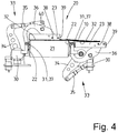
- Each coupling mechanism 33 has substantially three coupling arms, via a first coupling arm 34, a second coupling arm 35 and a third coupling arm 36.
- the first coupling arm 34 and the second coupling arm 35 are substantially straight.
- the first coupling arm 34 is non-rotatably connected at one end to an output shaft of the servomotor 30 for actuating the linkage 33.
- first coupling arm 34 is articulated with an end of the second coupling arm 35 facing this, namely pivotable about a horizontal axis of rotation parallel to the longitudinal edge 22 of the central part 21.
- An opposite end of the second coupling arm 35 is articulated to the third coupling arm 36, and also rotatable about an axis of rotation. This axis of rotation runs parallel to the axis of rotation between the first coupling arm 34 and the second coupling arm 35.
- the third coupling arm 36 has an arcuate or angled course.
- the arc or the bend extends over a range of 110 ° to 160 °, preferably 120 ° to 150 °. In the exemplary embodiment shown, the bend or the arc region amount to about 135 °.
- One end of the third coupling arm 36 is connected to a Swivel axis 37 rotatably connected.
- the pivot axis 37 defines at the same time the axis of rotation 31 of the respective longitudinal folding blade 23.
- the pivot axis 37 extends parallel to each one longitudinal edge 22 of the central part 21, with a small distance next to the longitudinal edge 22 and slightly below the upper run of the belt conveyor of the central part 21.
- An opposite end of the third coupling arm 36 is hinged about an axis of rotation 38 pivotally mounted on the respective longitudinal folding wing 23.
- This axis of rotation 38 extends parallel to the pivot axis 37.
- the axis of rotation 38 is associated eccentrically with the longitudinal folding blade 23, in such a way that it is removed by approximately one quarter of the width of the longitudinal folding blade 23 from its outer edge 39.
- the coupling arm 36 is associated with a further pivot axis 40, is hinged to the articulated second coupling arm 35, with its hinged to the first coupling arm 34 end opposite end.
- the axis of rotation 40 is closer to the axis of rotation 38 at one end of the coupling arm 36 than at the pivot axis 37 of the opposite end of the coupling arm 36. Due to the angled or arcuate design of the third coupling arm 36, the axis of rotation 40 is not on a line between the pivot axis 37 and the rotation axis 38, but (based on the representation of Fig. 2 ) below this line.
- pivot axis 37 and the axes of rotation 38 and 40 of the third coupling arm 36 lie on the corners of a triangle. This is an unequal triangle, wherein the axis of rotation 40 is slightly closer to the axis of rotation 38.
- the Fig. 3 shows an intermediate position of a folded by about 90 ° longitudinal folding blade 23, and that of (relative to the representation of Fig. 3 ) left longitudinal folding wing 23.
- the Fig. 4 shows the left longitudinal folding blade 23 in the final folding position, ie in an approximately 180 ° relative to in the Fig. 2 shown pivoted position in which the left longitudinal folding wing 23 has the left edge region of the garment 10 folded longitudinally, so that this longitudinally folded left edge region of the garment 10 is located on the central part thereof and the longitudinal longitudinal fold line extending approximately over the left longitudinal edge 22 of the central portion 21st located.
- This position of the left longitudinal fold line with respect to the left longitudinal edge 22 of the central part 21 is predetermined by the corresponding folding template.
- the longitudinal fold line although parallel to the left longitudinal edge 22 of the central part 21, but is offset from the longitudinal edge 22 in the direction of the center of the central part 21 slightly inward.
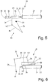
- FIGS. 5 and 6 show the starting position and the final folding position of the left longitudinal folding blade 23 in schematically illustrated coupling gear 33rd
- the first and the second coupling arm 34, 35 are approximately equal in length.
- the distance of the pivot axis 37 to the axis of rotation 38 is about the same size as the length of the coupling arms 34, 35. This distance can also be less, preferably by 10% to 20% ..
- the longitudinal folding blade 23 is pivoted about its pivot axis 37 only by about 4 ° to 6 °.
- This makes it possible with a relatively small servo motor 30, in particular a servo motor with relatively low power or a relatively low torque, to overcome the inertia of the L jossfaltklügels 23 and the components of the linkage 33 in an acceleration of the L jossfaltflügels 23 from its rest position.
- the situation is similar when braking or deceleration of the longitudinal folding blade 23 before reaching his in the Fig. 4 and 6 illustrated Endfaltwolf. However, here is a smaller or no reduction provided.
- the deceleration can also be done with a slight translation, which deviates significantly from the translation in motion of the longitudinal folding blade 23 between the initial and the final folding position.
- the translation during deceleration or deceleration of the longitudinal folding blade 23 is only about 1.4 to 1.7.
- the means, at 10 ° angular movement of the output shaft of the servomotor 30, the longitudinal folding blade 23 is pivoted between 14 ° to 17 °.
- the coupling gear allows a higher gear ratio, in which the longitudinal folding blade 23 can be pivoted relative to the angle of rotation of the output shaft of the servomotor 30 by a much larger pivoting range. This leads to an almost complete utilization of the available power and / or the available torque of the servomotor 30 in all pivot phases of the respective longitudinal folding blade 23. Because of this, the coupling mechanism 33 makes it possible with respect to the power or the maximum torque and also the size of relatively small sized servomotor 30 to use.
- the coupling mechanism 33 is formed so that at least in the starting position of the respective longitudinal folding blade 23, the output axis of the servomotor 30 and the rotation axis 40, whereby the free end of the second coupling arm 35 is connected to the third coupling arm 36, close together.
- the axis of rotation 40 between the second coupling arm 35 and the third coupling arm 36 and the output axis of the servomotor 30 are closest together. Consequently, the distance between the rotation axis 40 and the output axis of the servo motor 30, starting from the starting position of the longitudinal folding blade 23 becomes increasingly larger. However, the distance may become smaller again during pivoting of the longitudinal folding blade 23 before reaching the end folding station of the longitudinal folding flap 23.
- the output shaft of the servomotor 30 and the pivot axis 37 of the third coupling arm 36 of the linkage 33 do not change their distance because it is fixed end points of the coupling drive 33.
- the distance of the pivot axis 37 to the longitudinal center axis of the output shaft of the servomotor 30 is selected to be relatively small by one third to two thirds, preferably half the length of the first coupling arm 34 and / or second coupling arm 35 corresponds.
- PLC controls programmable logic controllers
- the longitudinal folding wings 23 always exert an equal compressive force on the longitudinally folded outer edge region of the relevant item of clothing 10 in their final fold position, regardless of the material thickness of the items of clothing 10.
- this pressing force it is possible to vary this pressing force in the manner of the fabric of the garments 10.
- the servo drives, in particular the servomotors 30 associated with the longitudinal folding wings 23, ensure that the items of clothing 10 are folded as required, possibly also as a function of their type of fabric, fabric thickness and / or intended use or type of item of clothing 10.
Landscapes
- Engineering & Computer Science (AREA)
- Textile Engineering (AREA)
- Folding Of Thin Sheet-Like Materials, Special Discharging Devices, And Others (AREA)
Abstract
Description
- Die Erfindung betrifft eine Vorrichtung zum Falten von Textilien, vorzugsweise Bekleidungsstücken, gemäß dem Oberbegriff des Anspruchs 1.
- Von im Fachjargon als Faltautomaten bezeichneten Vorrichtungen der hier angesprochenen Art werden Textilien, vor allem Bekleidungsstücke wie zum Beispiel Kittel, Hemden, Hosen oder dergleichen, gefaltet. Dies geschieht durch aufeinanderfolgendes Längs- und Querfalten bzw. Quer- und Längsfalten. Die gefalteten Textilien werden anschließend gestapelt und Stapel mehrerer übereinanderliegender gefalteter Textilien abgefördert.
- Bekannte Vorrichtungen zum Falten von Textilien verfügen über eine Längsfaltstation mit einer Längsfaltauflage aus einem Mittelteil und zwei gegenüberliegenden Längsrändern des Mittelteils zugeordneten Längsfaltflügel. Die Längsfaltflügel sind um parallel zu den Längsrändern des Mittelteils verlaufende Drehachsen verschwenkbar. Das Verschwenken der Längsfaltflügel erfolgt bei bekannten Vorrichtungen dieser Art pneumatisch, nämlich durch Pneumatikzylinder. Diese verfügen über mehrere Nachteile. Vor allem ermöglichen sie nur begrenzte Schwenkgeschwindigkeiten der Längsfaltflügel. Außerdem lassen sich die Endpositionen der Pneumatikzylinder nicht präzise und auch nicht lastsensibel anfahren.
- Der Erfindung liegt die Aufgabe zugrunde, eine Vorrichtung zum Falten von Textilien, insbesondere Bekleidungsstücken, zu schaffen, die eine hohe Faltleistung beim gleichwohl exakten und schonenden Falten, insbesondere Längsfalten, der Textilien bzw. Bekleidungsstücke zulässt.
- Eine Vorrichtung zur Lösung dieser Aufgabe weist die Merkmale des Anspruchs 1 auf. Demnach ist es vorgesehen, dass der Antrieb des mindestens einen, insbesondere jedes, Längsfaltflügels von einem Servoantrieb, vorzugsweise einem Servomotor, gebildet ist. Hierbei handelt es sich um präzise und lastabhängige steuerbare Elektromotoren, die ein rasches Verschwenken des oder des jeweiligen Längsfaltflügels zulassen. Das rasche Verschwenken der Längsfaltflügel führt zu hohen Faltleistungen. Die präzise Steuerbarkeit der Servomotoren ermöglicht die Beendigung des zum Längsfalten dienenden Schwenkvorgangs des jeweiligen Längsfaltflügels exakt nach dem Absolvieren des erforderlichen Schwenkwinkels. Dieser Schwenkwinkel bzw. Schwenkweg ist abhängig von der Textilart bzw. der Gewebeart der Bekleidungsstücke, vor allem die Dicke. Dadurch kann der Faltvorgang exakt an die Material- bzw. Gewebeart der Bekleidungsstücke oder sonstiger Textilien angepasst werden. Eine lastsensible Steuermöglichkeit der Servomotoren oder ähnlicher Servoantriebe stellt sicher, dass Textilien oder andere Bekleidungsstücke unterschiedlicher Material- bzw. Gewebeart nur mit einer bestimmten Kraft zusammengedrückt werden.
- Bevorzugt ist es vorgesehen, dass der jeweilige Servomotor über ein Koppelgetriebe, vorzugsweise ein mehrgliedriges Koppelgetriebe, mit dem ihm zugeordneten Längsfaltflügel verbunden ist. Das Koppelgetriebe ermöglicht eine den Anforderungen entsprechende Schwenkbewegung des jeweiligen Längsfaltflügels beim Längsfalten der Bekleidungsstücke oder sonstiger Textilien.
- Das Koppelgetriebe weist bevorzugt mindestens zwei an benachbarten Enden gelenkig miteinander verbundene Koppelarme auf. Bevorzugt verfügt das Koppelgetriebe über drei gelenkig miteinander verbundene Koppelarme. Die gelenkig miteinander verbundenen Koppelarme stellen eine Art Mehrgelenkkette dar, die es ermöglicht, die Längsfaltflügel auf erforderliche Weise zum Längsfalten der Textilien, insbesondere Bekleidungsstücke, zu verschwenken, und zwar insbesondere um etwa 180°, gegebenenfalls auch um bis zu 20° darüber oder darunter. Durch das Koppelgetriebe kann demnach jeder Längsfaltflügel sich mindestens annähernd auf einer Halbkreisbahn bewegen.
- Gemäß einer vorteilhaften Ausgestaltungsmöglichkeit der Vorrichtung ist eine drehend antreibbare Abtriebswelle des jeweiligen Servomotors mit einem freien Ende eines ersten Koppelarms unverdrehbar verbunden. Dadurch ist die Drehbewegung der Abtriebswelle des Servomotors über das Koppelgetriebe, insbesondere mindestens einen den ersten Koppelarm nachfolgenden Koppelarm, umsetzbar, die eine Bewegung, die zum gewünschten Verschwenken des jeweiligen Längsfaltflügels führt, und vor allem auch ein Verschwenken des jeweiligen Längsfaltflügels um etwa 180° ermöglicht.
- Eine besonders vorteilhafte Weiterbildungsmöglichkeit der Vorrichtung sieht es vor, das Koppelgetriebe so auszubilden, dass beim anfänglichen Verschwenken und/oder zum Schluss des Verschwenkens sich der Schwenkwinkel des jeweiligen Längsfaltflügels im Vergleich zum Drehwinkel der Abtriebswelle des Servomotors weniger ändert als der Verdrehwinkel des Servomotors. Es findet so mindestens in der anfänglichen Ausgangsstellung des Koppelgetriebes, also zu Beginn des Längsfaltvorgangs und/oder Ende des Längsfaltvorgangs, eine Untersetzung der Drehwinkeländerung der Abtriebswelle des Servomotors gegenüber der Schwenkwinkeländerung des jeweiligen Längsfaltflügels statt. Diese Untersetzung liegt bevorzugt im Bereich von 0,7 bis 0,3. Das bedeutet bei einem Verdrehen der Abtriebswelle des Servomotors um 90° beim Verschwenken des jeweiligen Längsfaltflügels um lediglich 63° bis 27°. Durch diese Untersetzung ist es mit einem kleinen Servomotor mit einer relativ geringen Leistung möglich, die nötige Kraft zum Beschleunigen des jeweiligen Längsfaltflügels aus seiner Anfangsposition heraus und vorzugsweise auch zum Abbremsen des Längsfaltflügels beim Erreichen seiner Endposition bereitzustellen.
- Eine andere Ausgestaltungsmöglichkeit der Vorrichtung sieht es vor, das Koppelgetriebe mit dem mindestens einen gelenkig mit dem ersten Koppelarm verbundenen zweiten Koppelarm zu versehen. Die zueinander gerichteten benachbarten Enden des ersten und zweiten Koppelarms bilden dann eine Schwenkachse. Dabei sind zu Beginn des Längsfaltvorgangs, wenn die Längsfaltflügel sich noch in ihrer Ausgangsstellung befinden, der erste und zweite Koppelarm in einer Relativstellung zueinander, in der sie bezogen auf die Schwenkachse an ihren miteinander verbundenen Enden einen spitzen Winkel einschließen, der bevorzugt zwischen 15° und 45° liegt. Aufgrund dieser Relativanordnung des ersten und zweiten Koppelarms zu Beginn des Längsfaltvorgans ist das von der Abtriebswelle des Servomotors auf das dieser zugeordnete Ende des ersten Koppelarms ausübende Drehmoment zur Beschleunigung des Koppelgetriebes und des diesem zugeordneten Längsfaltflügels aus der Ausgangsstellung relativ klein. Erst wenn das Koppelgetriebe mit dem Längsfaltflügel in Bewegung gesetzt ist, ändert sich die Relativposition insbesondere zwischen dem ersten und zweiten Koppelarm derart, dass der jeweilige Längsfaltflügel zunehmend schneller in die Längsfaltposition bewegt wird. Gegebenenfalls kann es sich analog beim Abbremsen des jeweiligen Längsfaltflügels nach Beendigung des Längsfaltvorgangs verhalten.
- Eine vorteilhafte Weiterbildungsmöglichkeit der Erfindung besteht darin, den letzten Koppelarm des Koppelgetriebes, der dem jeweiligen Längsfaltflügel zugeordnet ist, als einen Winkelarm und/oder mehrarmigen Koppelarm auszubilden. Demnach verfügt dieser Koppelarm über mehr als zwei Stellen, die eine Schwenkachse und Drehachsen zur Anlenkung am Längsfaltflügel und an einem vorangehenden Koppelarm bilden.
- Vorzugsweise ist mit einem Ende der Koppelarm gelenkig mit jeweils einem Längsfaltflügel verbunden, während das gegenüberliegende Ende an eine ortsfeste Schwenkachse angelenkt ist, die parallel zur Transportrichtung des zu faltenden Bekleidungsstücks oder eines anderen textilen Gegenstands verläuft. Zwischen den Enden des dritten Koppelarms ist ein freies Ende des zum Beispiel zweiten Koppelarms des Koppelgetriebes angelenkt. Infolge der Anlenkung dieses dritten Koppelarms an einer ortsfesten Schwenkachse kann das Koppelgetriebe eine definierte Bewegung ausführen und dabei der jeweilige Längsfaltflügel auf einer definierten Bahn verschwenkt werden. Dabei kann der Längsfaltflügel zur Anpassung an unterschiedliche Gewebe- bzw. Materialdicken des jeweils zu faltenden Textilgegenstands auch relativ zum ihm zugeordneten Ende des dritten Koppelarms verschwenkt werden.
- Bevorzugt ist es vorgesehen, die Abtriebswelle des Servomotors parallel verlaufend zur ortsfesten Schwenkachse des am jeweiligen Längsfaltflügel angelenkten dritten Koppelarms anzuordnen. Durch die parallele Drehachse der Abtriebswelle des Servomotors und Schwenkachse des dritten Koppelarms sind alle Koppelarme des Koppelgetriebes in einer Ebene bewegbar, die quer zur Dreh- und Schwenkachse verläuft.
- Eine andere vorteilhafte Ausgestaltungsmöglichkeit der Vorrichtung sieht es vor, dass der dem jeweiligen Längsfaltflügel zugeordnete dritte Koppelarm abgewinkelt ist, vorzugsweise um mehr als 90°, insbesondere 120° bis 160°. Dadurch lässt sich das gesamte Koppelgetriebe raumsparend ausbilden. Infolge der Abwinklung kann der dritte Koppelarm an seiner ortsfesten Schwenkachse, der Längsfaltklappe und dem vorangehenden, vorzugsweise zweiten, Koppelarm angelenkt werden. Bevorzugt verfügt der abgewinkelte dritte Koppelarm über zwei freie Enden, bei denen ein freies Ende der ortsfesten Schwenkachse und das andere freie Ende der Längsfaltklappe zugeordnet ist. An einer zwischen diesen Enden liegenden Stelle ist der abgewinkelte dritte Koppelarm mit einem vorangehenden Koppelarm gelenkig verbunden. Diese Stelle liegt bevorzugt dichter an dem am Längsfaltflügel angekoppelten Ende des dritten Koppelarms als dem seiner ortsfesten Schwenkachse zugeordneten Ende. Das trägt auch zur angestrebten Untersetzung zu Beginn des Faltvorgangs, nämlich zum Herausbewegen des jeweiligen Längsfaltflügels aus seiner heruntergeschwenkten Ausgangsstellung und/oder zum Abbremsen des jeweiligen Längsfaltflügels in der um vorzugsweise 180° umgeschwenkten Längsfaltstellung, bei.
- Es ist denkbar, die Vorrichtung mit weiteren Servomotoren zu versehen. Ein Servomotor ist bevorzugt einem Zuführförderer von an Bügeln hängenden Bekleidungsstücken oder sonstigen Textilien in Richtung zur ersten Faltstation, beispielsweise einer Querfaltstation oder der Längsfaltstation, zugeordnet. Ein anderer Servomotor kann einem Abförderer zum Herausziehen eingeklappter Bügel aus den Bekleidungsstücken oder sonstigen Textilien und zum Abtransport leerer Bügel zugeordnet sein. Auch im Zusammenhang mit den vorgenannten Transportaufgaben erfüllen Servomotoren wegen ihrer individuellen Steuerungsmöglichkeiten und relativ großer Geschwindigkeiten kurze Taktzeiten und/oder einen exakten, störungsfreien Bewegungsablauf der Vorrichtung.
- Ein bevorzugtes Ausführungsbeispiel der Vorrichtung wird nachfolgend anhand der Zeichnung näher erläutert. In dieser zeigen:
- Fig. 1
- eine schematische, teilweise geschnittene Seitenansicht der Vorrichtung,
- Fig. 2
- einen Querschnitt durch eine Längsfaltstation mit beiden sich in der Ausgangsstellung befindenden Längsfaltflügeln,
- Fig. 3
- einen Querschnitt durch die Längsfaltstation analog zu
Fig. 2 mit einem teilweise hochgeschwenkten Längsfaltflügel, - Fig. 4
- einen Schnitt durch die Längsfalteinrichtung analog zu den
Fig. 2 und 3 bei einem in die Endfaltstellung verschwenkten Längsfaltflügel, - Fig. 5
- eine vereinfachte Prinzipdarstellung der Längsfaltstation mit einem in der Ausgangsstellung (analog zu
Fig. 2 ) sich befindenden Längsfaltflügel, und - Fig. 6
- eine Darstellung analog zu
Fig. 5 mit in der Endfaltstellung (analog zurFig. 4 ) sich befindendem Längsfaltflügel. - Die
Fig. 1 zeigt schematisch eine Vorrichtung zum Falten und anschließenden Stapeln von Bekleidungsstücken 10 oder auch anderen textilen Gegenständen. Die Vorrichtung verfügt über eine Falteinrichtung 11 und eine dieser nachgeordneten Stapeleinrichtung 12. Der hier gezeigten Vorrichtung werden die Bekleidungsstücke 10 an in den Figuren nicht gezeigten Transportbügeln hängend zugeführt. Die Erfindung ist aber hierauf nicht beschränkt. Die Bekleidungsstücke 10 können auf andere Weise der Vorrichtung zugeführt werden. Außerdem eignet sich die Erfindung auch für Vorrichtungen, die über keine Stapeleinrichtung 12 verfügen. - Die Zufuhr des jeweils an einem Transportbügel hängenden Bekleidungsstücks 10 zur Falteinrichtung 11 der Vorrichtung erfolgt mit einem Bügelzuführförderer 13. Dieser verfügt über eine vorzugsweise geradlinige Förderstrecke, an der Bügelhaken der Transportbügel hängen, und zwar vorzugsweise an einem Schlitten, der von einem Förderstrang längs der Förderstrecke des Bügelzuführförderers 13 weiterbewegt wird. Der Förderstrang des Bügelzuführförderers 13 wird von einem Servomotor 14 angetrieben.
- Gegen Ende des Bügelzuführförderers 13 gelangen die Bekleidungsstücke 10 auf einen Zuförderer 15. Sobald die Bekleidungsstücke 10 den Zuförderer 15 erreicht haben, wird der Transportbügel eingeklappt und von einem leicht in Förderrichtung ansteigenden Bügelauszugförderer 16 aus dem Bekleidungsstück 10 herausgezogen und abtransportiert. Dabei hängen die Transportbügel mit ihren Bügelhaken auch an einem Schlitten eines Bügelauszugförderers 16, der von einem umlaufenden Förderstrang entlang der Förderstrecke des Bügelauszugförderers 16 weitertransportiert wird. Der Antrieb des Förderstrangs des Bügelauszugförderers 16 erfolgt durch einen weiteren, dem Bügelauszugförderer 16 zugeordneten Servomotor 17.
- Vom Zuförderer 15 gelangt das jeweilige Bekleidungsstück 10 in den Bereich einer ersten Querfaltstation 18. Der Zuförderer 15 kann bereits Bestandteil der ersten Querfaltstation 18 sein, nämlich einen ersten Förderer derselben bilden. Bei Bekleidungsstücken 10 mit Ärmeln werden diese vor Erreichen der ersten Querfaltstation 18 oder am Anfang derselben vor der ersten Querfaltung des Bekleidungsstücks 10 umgelegt auf ein Rumpfteil des Bekleidungsstücks 10. Die erste Querfaltstation 18 ist in an sich bekannter Weise mit einem Reversier- und/oder Zwischenförderer 19 versehen, der durch Antrieb in unterschiedliche Richtungen das Bekleidungsstück 10 durch einen Querfaltspalt transportiert und dabei zwei jeweils eine Hälfte des Bekleidungsstücks 10 umfassende Lagen des Bekleidungsstücks 10 übereinanderlegt. Von einem Zwischenförderer 19 wird dann das mit einer ersten Querfaltung versehene Bekleidungsstück 10 zur Längsfaltstation 20 transportiert.
- Die Längsfaltstation 20 verfügt über ein im gezeigten Ausführungsbeispiel ortsfestes Mitteilteil 21 und zwei gegenüberliegenden Längsrändern 22 zugeordnete Längsfaltflügel 23. Die Längsfaltflügel 23 sind gleich ausgebildet, jedoch in einer spiegelverkehrten Orientierung den gegenüberliegenden Längsrändern 22 des Mitteilteils 21 zugeordnet. Das Mitteilteil 21 der Längsfaltstation 20 der gezeigten Vorrichtung ist als ein Gurtförderer ausgebildet mit mehreren nebeneinanderliegenden, schmalen umlaufenden Fördergurten oder nur einem breiten umlaufenden Fördergurt, wovon das Bekleidungsstück 10 in die Längsfaltstation 20 eintransportierbar und nach dem Längsfalten abtransportierbar ist. Die Förderrichtung des nur einen Fördergurts oder auch mehrere nebeneinanderliegende Fördergurte aufweisenden Mitteilteils 21 verläuft in Längsrichtung der Längsfaltstation 20 und der Längsränder 22 des Mittelteils 21. Die Längsrichtung der Längsfaltflügel 23 entspricht auch der Förderrichtung.
- Die Längsfaltstation 20 weist vorzugsweise zwei Faltschablonen oder gegebenenfalls auch nur eine in den Figuren nicht dargestellte Faltschablone auf. Hierbei handelt es sich um längliche Zungen, die durchgehend über die gesamte Längsrichtung der Längsfaltstation 20, insbesondere ihres Mitteilteils 21, verlaufen. Bei mehreren Faltschablonen sind diese in der Nähe der Längsränder 22 mit Abstand oberhalb des Obertrums des Gurtförderers des Mittelteils 21 angeordnet, wobei gegebenenfalls der Abstand der Faltschablonen zueinander bzw. untereinander verändert werden kann zur Anpassung an die gewünschte Faltbreite des Bekleidungsstücks 10 in der Längsfaltstation 20. Das jeweilige Bekleidungsstück 10 wird zwischen der mindestens einen Faltschablone und dem Obertrum des Gurtförderers des Mittelteils 21 hindurch in und durch die Längsfaltstation 20 transportiert. Dabei befindet sich die mindestens eine Faltschablone über dem jeweils längs zu faltenden Bekleidungsstück 10. Auf dem Gurtförderer des Mittelteils 21 zum Hindurchfördern der Bekleidungsstücke 10 durch die Längsfaltstation 20 liegt das längs zu faltenden Bekleidungsstück 10 auf.
- In der Längsfaltstation 20 werden gegenüberliegende Randbereiche des Bekleidungsstücks 10 nacheinander um etwa 180° umgelegt auf die sich auf dem Mitteilteil 21 der Längsfaltstation 20 befindende Rumpfmitte des Bekleidungsstücks 10.
- Nach dem Längsfalten in der Längsfaltstation 20 wird das einmal quer und einmal längs gefaltete Bekleidungsstück 10 bei der hier gezeigten Vorrichtung durch eine nachfolgende zweite Querfaltstation 24 transportiert und in dieser bedarfsweise (also optional) ein zweites Mal quer gefaltet. Auch diese zweite Querfaltstation 24 ist in an sich bekannter Weise ausgebildet.
- Die fertig gefalteten Bekleidungsstücke 10 werden von der zweiten Querfaltstation 24 zu einer Abstapelstation 25 transportiert. Diese verfügt über einen Ablagetisch, der als ein kurzer Gurtförderer 26 ausgebildet ist. Der kurze Gurtförderer 26 ist von einer Hubeinrichtung 27 auf- und abbewegbar, und zwar vorzugsweise taktweise. Dadurch bilden der kurze Gurtförderer 26 und die diesem zugeordnete Hubeinrichtung 27 der Abstapelstation 25 ein Hubband. Die Hubeinrichtung 27 verfügt über einen Linearantrieb 28 zum taktweisen Auf- und Abbewegen des Gurtförderers 26. Die Betätigung des Linearantriebs erfolgt durch einen Servomotor 29. Dadurch ist vom Linearantrieb 28 der kurze Gurtförderer 26 rasch und um einen exakt den Anforderungen entsprechenden Weg absenkbar. Dieses Absenken erfolgt derart, dass auf dem kurzen Gurtförderer 26 der Abstapelstation 25 gefaltete Bekleidungsstücke 10 nach und nach übereinander abgelegt werden können zur Bildung eines Stapels. Nachdem auf dem kurzen Gurtförderer 26 der Abstapelstation 25 die gewünschte Anzahl von gefalteten Bekleidungsstücken 10 abgelegt worden ist, also der Stapel mit mehreren Bekleidungsstücken 10 komplett ist, wird vom Linearantrieb 28 der kurze Gurtförderer 26 mit dem daraufliegenden Stapel mehrerer gefalteteter Bekleidungsstücke 10 zunächst herabgefahren und anschließend wieder hochgefahren zum den Anforderungen entsprechenden Zusammenpressen des Stapels. Dazu wird vor dem erneuten Hochfahren der Hubeinrichtung 27 ein Gegenhalter, beispielsweise eine Andruckplatte, über den Stapel gefahren und der Stapel von unten gegen diese Andruckplatte gepresst, und zwar mit einer vorbestimmten Kraft. Danach wird vom Linearantrieb 28 der kurze Gurtförderer 26 mit dem darauf befindlichen Stapel wieder etwas heruntergefahren und durch einen Antrieb des kurzen Gurtförderer 26 der Stapel auf ein in der
Fig. 1 nicht gezeigtes Abförderband übergeben. Dazu ist der kurze Gurtförderer 26 und die Abstapelstation 25 mit einem eigenen Antrieb versehen. Dieser Antrieb kann auf verschiedene Weise realisiert werden. Beispielsweise kann es sich beim Antrieb auch um einen separaten, eigenen Servomotor des kurzen Gurtförderers 26 handeln. - Jeder der gleich ausgebildeten und spiegelverkehrt den gegenüberliegenden Längsrändern 22 des Mittelteils 21 der Längsfaltstation 20 zugeordneten Längsfaltflügel 23 ist von einem Servoantrieb, vorzugsweise einem elektrisch betriebenen Servomotor 30, um eine mit parallelem Abstand neben dem jeweiligen Längsrand 22 des Mittelteils 21 verlaufende Drehachse 31 in entgegengesetzten Richtungen um etwa 180° umklappbar. Dabei verlaufen die Drehachsen 31 wie die Längsränder 22 des Mittelteils 21 in Längsrichtung der Längsfaltstation 20.
- Die
Fig. 2 zeigt beide Längsfaltflügel 23 in ihrer horizontalen Ausgangsstellung auf gegenüberliegenden Seiten des Mittelteils 21. Die in der Ausgangsstellung horizontalen Auflageflächen 32 für das Bekleidungsstück 10 auf den Längsfaltflügeln 23 verlaufen dabei etwa in der gleichen horizontalen Ebene der Längsfaltstation 20. Dabei verbreitern die Auflageflächen 32 des Längsfaltflügels 23 das Mittelteil 21 auf beiden Seiten. Auf der Auflagefläche 32 jedes Längsfaltflügels 23 liegt ein Randbereich des in der Längsfaltstation 20 von jedem Längsfaltflügel 23 längs zu faltenden Bekleidungsstücks 10 auf. Dieser Randbereich ist vorzugsweise etwas schmaler als ein Mittelbereich des Bekleidungsstücks 10, der auf dem Mittelteil 21 der Längsfaltstation 20 aufliegt. Demzufolge sind die Auflageflächen 32 der Längsfaltflügel 23 etwas schmaler als die Breite des Mittelteils 21. - Zwischen jedem Längsfaltflügel 23 und dem Servomotor 30 zum Verschwenken jedes Längsfaltflügels 23 ist ein Koppelgetriebe 33 vorgesehen. Die Koppelgetriebe 33 beider Längsfaltflügel 23 sind abgesehen von ihrer spiegelverkehrten Anordnung gleich ausgebildet. Jedes Koppelgetriebe 33 verfügt im Wesentlichen über drei Koppelarme, und zwar über einen ersten Koppelarm 34, einen zweiten Koppelarm 35 und einen dritten Koppelarm 36. Der erste Koppelarm 34 und der zweite Koppelarm 35 sind im Wesentlichen gerade ausgebildet. Der erste Koppelarm 34 ist mit einem Ende unverdrehbar mit einer Abtriebswelle des Servomotors 30 zum Betätigen des Koppelgetriebes 33 verbunden. Ein gegenüberliegendes Ende des ersten Koppelarms 34 ist mit einem zu diesem weisenden Ende des zweiten Koppelarms 35 gelenkig, nämlich um eine horizontale Drehachse parallel zum Längsrand 22 des Mittelteils 21 verschwenkbar, verbunden. Ein gegenüberliegendes Ende des zweiten Koppelarms 35 ist an dem dritten Koppelarm 36 angelenkt, und zwar auch um eine Drehachse drehbar. Diese Drehachse verläuft parallel zur Drehachse zwischen dem ersten Koppelarm 34 und dem zweiten Koppelarm 35.
- Der dritte Koppelarm 36 verfügt über einen bogenförmigen bzw. abgewinkelten Verlauf. Der Bogen bzw. die Abwinklung erstreckt sich über einen Bereich von 110° bis 160°, vorzugsweise 120° bis 150°. Im gezeigten Ausführungsbeispiel betragen die Abwinklung oder der Bogenbereich etwa 135°. Ein Ende des dritten Koppelarms 36 ist mit einer Schwenkachse 37 drehbar verbunden. Diese Schwenkachse 37 definiert gleichzeitig die Drehachse 31 des jeweiligen Längsfaltflügels 23. Die Schwenkachse 37 verläuft parallel neben jeweils einem Längsrand 22 des Mittelteils 21, und zwar mit geringem Abstand neben dem Längsrand 22 und etwas unter dem Obertrum des Gurtförderers des Mittelteils 21. Ein gegenüberliegendes Ende des dritten Koppelarms 36 ist um eine Drehachse 38 schwenkbar am jeweiligen Längsfaltflügel 23 angelenkt. Diese Drehachse 38 verläuft parallel zur Schwenkachse 37. Die Drehachse 38 ist außermittig dem Längsfaltflügel 23 zugeordnet, und zwar so, dass sie um etwa ein Viertel der Breite des Längsfaltflügels 23 von seinem äußeren Rand 39 entfernt ist.
- Mit Abstand von der Drehachse 38 ist dem Koppelarm 36 eine weitere Schwenkachse 40 zugeordnet, an der gelenkig der zweite Koppelarm 35 angelenkt ist, und zwar mit seinem dem am ersten Koppelarm 34 angelenkten Ende gegenüberliegenden Ende. Die Drehachse 40 befindet sich dichter an der Drehachse 38 an einem Ende des Koppelarms 36 als an der Schwenkachse 37 des gegenüberliegenden Endes des Koppelarms 36. Infolge der abgewinkelten bzw. bogenförmigen Ausbildung des dritten Koppelarms 36 liegt die Drehachse 40 nicht auf einer Linie zwischen der Schwenkachse 37 und der Drehachse 38, sondern (bezogen auf die Darstellung der
Fig. 2 ) unterhalb dieser Linie. Aufgrund dessen liegen die Schwenkachse 37 und die Drehachsen 38 und 40 des dritten Koppelarms 36 auf den Ecken eines Dreiecks. Hierbei handelt es sich um ein ungleichschenkliges Dreieck, wobei die Drehachse 40 etwas dichter an der Drehachse 38 liegt. - Die
Fig. 3 zeigt eine Zwischenstellung eines um etwa 90° hochgeschwenkten Längsfaltflügels 23, und zwar des (bezogen auf die Darstellung derFig. 3 ) linken Längsfaltflügels 23. DieFig. 4 zeigt den linken Längsfaltflügel 23 in der Endfaltstellung, also in einer um etwa 180° gegenüber der in derFig. 2 dargestellten Ausgangsstellung umgeschwenkten Stellung, in der der linke Längsfaltflügel 23 den linken Randbereich des Bekleidungsstücks 10 längsgefaltet hat, so dass dieser längsgefaltete linke Randbereich des Bekleidungsstücks 10 auf dem Mittelteil desselben liegt und die in Längsrichtung verlaufende Längsfaltlinie sich etwa über dem linken Längsrand 22 des Mittelteils 21 befindet. Diese Position der linken Längsfaltlinie bezogen zum linken Längsrand 22 des Mittelteils 21 wird durch die entsprechende Faltschablone vorherbestimmt. Durch Verstellung der Faltschablonen ist es denkbar, dass die Längsfaltlinie zwar parallel zum linken Längsrand 22 des Mittelteils 21 verläuft, aber vom Längsrand 22 in Richtung zur Mitte des Mittelteils 21 etwas nach innen versetzt ist. - Die
Fig. 5 und 6 zeigen die Ausgangsstellung und die Endfaltstellung des linken Längsfaltflügels 23 bei schematisch dargestelltem Koppelgetriebe 33. - Aus der schematischen Darstellung des Koppelgetriebes 33 wird ersichtlich, dass der erste und der zweite Koppelarm 34, 35 etwa gleich lang sind. Am dritten Koppelarm 36 ist der Abstand der Schwenkachse 37 zur Drehachse 38 etwa genauso groß wie die Länge der Koppelarme 34, 35. Dieser Abstand kann aber auch geringer sein, vorzugsweise um 10% bis 20%.. Der Abstand der dritten Achse, nämlich der Drehachse 40, des Koppelarms 36 von einer gedachten Verbindungslinie zwischen der Schwenkachse 37 und der Drehachse 38 ist hingegen etwas kleiner als der Abstand zwischen der Schwenkachse 37 und der Drehachse 38, beträgt nur etwa zwei Drittel des gesamten Abstands zwischen der Schwenkachse 37 und der Drehachse 38.
- Aus der die Ausgangsstellung des Koppelgetriebes mit dem Längsfaltflügel 23 zeigenden Darstellung der
Fig. 5 wird ersichtlich, dass zu Beginn des Schwenkvorgangs des Längsfaltflügels 23 der erste und der zweite Koppelarm 34 und 35 unter einem spitzen Winkel zueinander verlaufen (gemessen an den miteinander verbundenen und zueinander gerichteten Enden der Koppelarme 34 und 35). Dieser spitze Winkel beträgt im gezeigten Ausführungsbeispiel etwa 25°, kann aber hiervon um +/- 20° abweichen. Infolge dieses spitzen Winkels der Koppelarme 34 und 35 in der Ausgangsstellung des Längsfaltflügels 23 und des Koppelgetriebes 33 ist anfänglich eine Untersetzung des Schwenkwegs der Abtriebswelle des Servomotors 30 zum Verschwenkwinkel des jeweiligen Längsfaltflügels 23 gegeben. Diese Untersetzung beträgt im gezeigten Ausführungsbeispiel etwa 0,4 bis 0,6. Das heißt, bei einem Schwenkwinkel der Abtriebswelle des Servomotors 30 von zum Beispiel 10° wird der Längsfaltflügel 23 um seine Schwenkachse 37 nur um etwa 4° bis 6° verschwenkt. Dadurch ist es mit einem relativ kleinen Servomotor 30, insbesondere einem Servomotor mit relativ geringer Leistung bzw. einem relativen geringen Drehmoment, möglich, die Massenträgheit des Längsfaltflügels 23 und der Komponenten des Koppelgetriebes 33 bei einem Beschleunigen des Längsfaltflügels 23 aus seiner Ruhestellung zu überwinden. Analog verhält es sich beim Abbremsen bzw. Verzögern des Längsfaltflügels 23 vor Erreichen seiner in denFig. 4 und6 dargestellten Endfaltstellung. Jedoch ist hier eine kleinere oder keine Untersetzung vorgesehen. Gegebenenfalls kann das Abbremsen auch mit einer geringfügigen Übersetzung, die von der Übersetzung in Bewegung des Längsfaltflügels 23 zwischen der Ausgangs- und der Endfaltstellung deutlich abweicht, erfolgen. Die Übersetzung beim Abbremsen bzw. Verzögern des Längsfaltflügels 23 beträgt nur etwa 1,4 bis 1,7. Das heißt, bei 10° Winkelbewegung der Abtriebswelle des Servomotors 30 wird der Längsfaltflügel 23 zwischen 14° bis 17° verschwenkt. - Zwischen der Ausgangsstellung und Endfaltstellung ermöglicht das Koppelgetriebe eine höhere Übersetzung, bei der der Längsfaltflügel 23 bezogen auf den Drehwinkel der Abtriebswelle des Servomotors 30 um einen vielfach größeren Schwenkbereich verschwenkt werden kann. Das führt zu einer in allen Schwenkphasen des jeweiligen Längsfaltflügels 23 nahezu vollständigen Ausnutzung der zur Verfügung stehenden Leistung und/oder des zur Verfügung stehenden Drehmoments des Servomotors 30. Aufgrund dessen ermöglicht es das Koppelgetriebe 33, einen hinsichtlich der Leistung bzw. des maximalen Drehmoments und auch der Baugröße relativ klein dimensionierten Servomotor 30 einzusetzen.
- Darüber hinaus ist das Koppelgetriebe 33 so ausgebildet, dass zumindest in der Ausgangsstellung des jeweiligen Längsfaltflügels 23 die Abtriebsachse des Servomotors 30 und die Drehachse 40, womit das freie Ende des zweiten Koppelarms 35 mit dem dritten Koppelarm 36 verbunden ist, dicht beieinanderliegen. Vorzugsweise ist vorgesehen, dass in der Ausgangsstellung die Drehachse 40 zwischen dem zweiten Koppelarm 35 und dem dritten Koppelarm 36 sowie die Abtriebsachse des Servomotors 30 am dichtesten zusammenliegen. Demzufolge wird der Abstand zwischen der Drehachse 40 und der Abtriebsachse des Servomotors 30 ausgehend von der Ausgangsstellung des Längsfaltflügels 23 zunehmend größer. Der Abstand kann aber während des Verschwenkens des Längsfaltflügels 23 vor Erreichen der Endfaltstation der Längsfaltklappe 23 wieder kleiner werden. Die Abtriebswelle des Servomotors 30 und die Schwenkachse 37 des dritten Koppelarms 36 des Koppelgetriebes 33 verändern ihren Abstand nicht, weil es sich dabei um fixe Endpunkte des Koppeltriebes 33 handelt. Der Abstand der Schwenkachse 37 zur Längsmittelachse der Abtriebswelle des Servomotors 30 ist aber relativ klein gewählt, indem er ein Drittel bis zwei Drittel, vorzugsweise die halbe Länge, des ersten Koppelarms 34 und/oder zweiten Koppelarms 35 entspricht.
- Der Servomotor 30 ist ebenso wie die übrigen Servomotoren elektromotorisch angetrieben. Es handelt sich hierbei um Elektromotoren mit speicherprogrammierbaren Steuerungen (SPS Steuerungen). Solche Servomotoren, insbesondere der Servomotor 30, lassen sich hinsichtlich ihrer Drehzahl und damit hinsichtlich des maximal abgebbaren Drehmoments exakt bedarfsgerecht steuern. Insbesondere können die Servomotoren beliebig programmiert werden, insbesondere mit beliebigen Drehzahlverläufen. Auch ist es möglich, zumindest Servomotoren 30 für die Betätigung der Koppelgetriebe 33 der Längsfaltflügel 23 lastsensitiv zu steuern. Dann ist es möglich, den Faltweg und Faltwinkel der Längsfaltflügel 23 an unterschiedliche Materialien, insbesondere unterschiedlich dicke Materialien, der Bekleidungsstücke 10 anzupassen. Das kann derart erfolgen, dass die Längsfaltflügel 23 in ihrer Endfaltstellung unabhängig von der Materialdicke der Bekleidungsstücke 10 stets eine gleiche Druckkraft auf den längsgefalteten äußeren Randbereich des betreffenden Bekleidungsstücks 10 ausüben. Außerdem ist es möglich, diese Druckkraft nach Art des Gewebes der Bekleidungsstücke 10 zu variieren. Dadurch gewährleisten die Servoantriebe, insbesondere die den Längsfaltflügeln 23 zugeordneten Servomotoren 30, ein bedarfsgerechtes Falten der Bekleidungsstücke 10, und zwar gegebenenfalls auch in Abhängigkeit von ihrer Gewebeart, Gewebedicke und/oder der Verwendungszweck bzw. die Art des Bekleidungsstücks 10.
Bezugszeichenliste: 10 Bekleidungsstück 36 Koppelarm 11 Falteinrichtung 37 Schwenkachse 12 Stapeleinrichtung 38 Drehachse 13 Bügelzuführförderer 39 äußerer Rand 14 Servomotor 40 Drehachse 15 Zuförderer 16 Bügelauszugförderer 17 Servomotor 18 erste Querfaltstation 19 Zwischenförderer 20 Längsfaltstation 21 Mitteilteil 22 Längsrand 23 Längsfaltflügel 24 zweite Querfaltstation 25 Abstapelstation 26 kurzer Gurtförderer 27 Hubeinrichtung 28 Linearantrieb 29 Servomotor 30 Servomotor 31 Drehachse 32 Auflagefläche 33 Koppelgetriebe 34 Koppelarm 35 Koppelarm
Claims (13)
- Vorrichtung zum Falten von Textilien, vorzugsweise Bekleidungsstücken (10), mit mindestens einer Längsfaltstation (20), die wenigstens eine Faltschablone und mindestens einen von einem Antrieb schwenkbaren Längsfaltflügel (23) aufweist, dadurch gekennzeichnet, dass der Antrieb des mindestens einen Längsfaltflügels (23) als ein Servoantrieb ausgebildet ist.
- Vorrichtung nach Anspruch 1, dadurch gekennzeichnet, dass der Servoantrieb über ein vorzugsweise mehrgliedriges Koppelgetriebe (33) mit dem oder dem jeweiligen Längsfaltflügel (23) verbunden ist.
- Vorrichtung nach Anspruch 2, dadurch gekennzeichnet, dass das Koppelgetriebe (33) mindestens zwei an benachbarten Enden gelenkig miteinander verbundene Koppelarme (34, 35) aufweist.
- Vorrichtung nach Anspruch 2 oder 3, dadurch gekennzeichnet, dass eine drehend antreibbare Abtriebswelle des Servoantrieb mit einem freien Ende eines ersten Koppelarms (34) unverdrehbar verbunden ist.
- Vorrichtung nach einem der Ansprüche 2 bis 4, dadurch gekennzeichnet, dass das Koppelgetriebe (33) derart ausgebildet ist, dass beim anfänglichen Verschwenken und/oder zum Schluss des Verschwenkens sich der Schwenkwinkel des jeweiligen Längsfaltflügels (23) weniger ändert als der Drehwinkel der Abtriebswelle des Servorantriebs.
- Vorrichtung nach einem der vorhergehenden Ansprüche, dadurch gekennzeichnet, dass das Koppelgetriebe (33) mindestens einen gelenkig mit dem ersten Koppelarm (34) verbundenen zweiten Koppelarm (35) aufweist, der beim anfänglichen Verschwenken des jeweiligen Längsfaltbügels (23) aus seiner Ausgangsstellung einen spitzen Winkel zum ersten Koppelarm (34) einschließt, der vorzugsweise zwischen 15° und 45° liegt.
- Vorrichtung nach einem der vorhergehenden Ansprüche, dadurch gekennzeichnet, dass der letzte (dritte) Koppelarm (36) als ein mehrarmiger Koppelarm (36) mit vorzugsweise drei Ankopplungsstellen ausgebildet ist, dessen Anlenkungsstelle zwischen entgegengesetzten Enden des Koppelarms (36) gelenkig mit dem freien Ende eines ihm in Richtung zum Servoantrieb vorgeordneten zweiten Koppelarms (35) verbunden ist.
- Vorrichtung nach einem der vorhergehenden Ansprüche, dadurch gekennzeichnet, dass ein letzter (dritter) Koppelarm (36) des Koppelgetriebes (33) mit einem Ende drehbar mit dem ihm zugeordneten Längsfaltflügel (23) verbunden ist und ein gegenüberliegendes Ende dieses Koppelarms an einer ortsfesten Drehachse (38) angelenkt ist.
- Vorrichtung nach einem der vorhergehenden Ansprüche, dadurch gekennzeichnet, dass die Abtriebswelle des Servoantriebs parallel zur Schwenkachse (37) des am jeweiligen Längsfaltflügel (23) angelenkten Koppelarms (36) verläuft.
- Vorrichtung nach einem der vorhergehenden Ansprüche, dadurch gekennzeichnet, dass der dem Längsfaltflügel (23) zugeordnete Koppelarm (36) abgewinkelt ist, vorzugsweise um mehr als 90°, insbesondere um 120° bis 160°.
- Vorrichtung nach einem oder mehreren der vorhergehenden Ansprüche, dadurch gekennzeichnet, dass der Servoantrieb als Servomotor (30), vorzugsweise ein elektrisch betriebener Servomotor (30), ausgebildet ist.
- Vorrichtung nach einem der vorhergehenden Ansprüche, dadurch gekennzeichnet, dass ein Zuförderer (15) für an Bügeln hängenden Bekleidungsstücken (10) von einem Servomotor (14) antreibbar ist.
- Vorrichtung nach einem der vorhergehenden Ansprüche, dadurch gekennzeichnet, dass ein Abförderer von eingeklappten Bügeln von einem Servomotor (17) antreibbar ist.
Applications Claiming Priority (2)
| Application Number | Priority Date | Filing Date | Title |
|---|---|---|---|
| DE102016005751 | 2016-05-13 | ||
| DE102016007100.1A DE102016007100A1 (de) | 2016-05-13 | 2016-06-10 | Vorrichtung zum Falten von Textilien, vorzugsweise Bekleidungsstücke |
Publications (2)
| Publication Number | Publication Date |
|---|---|
| EP3243955A1 true EP3243955A1 (de) | 2017-11-15 |
| EP3243955B1 EP3243955B1 (de) | 2023-02-22 |
Family
ID=58632727
Family Applications (1)
| Application Number | Title | Priority Date | Filing Date |
|---|---|---|---|
| EP17000664.7A Active EP3243955B1 (de) | 2016-05-13 | 2017-04-20 | Vorrichtung zum falten von textilien, vorzugsweise bekleidungsstücke |
Country Status (2)
| Country | Link |
|---|---|
| EP (1) | EP3243955B1 (de) |
| DK (1) | DK3243955T3 (de) |
Cited By (2)
| Publication number | Priority date | Publication date | Assignee | Title |
|---|---|---|---|---|
| CN110359262A (zh) * | 2019-07-18 | 2019-10-22 | 东北大学 | 一种用于服装自动化生产线的服装翻面折叠装置 |
| CN114890066A (zh) * | 2022-05-27 | 2022-08-12 | 日照大象房屋建设有限公司 | 建筑模块操作平台转向输送装置 |
Families Citing this family (1)
| Publication number | Priority date | Publication date | Assignee | Title |
|---|---|---|---|---|
| IT202300020967A1 (it) | 2023-10-09 | 2025-04-09 | Danilo Pastorelli | Apparato di piegatura per capi in tessuto e relativo metodo di piegatura |
Citations (3)
| Publication number | Priority date | Publication date | Assignee | Title |
|---|---|---|---|---|
| US4411082A (en) * | 1981-10-08 | 1983-10-25 | Dubix | Laundry ironing device with pivoted blade folder |
| WO2012046227A1 (en) * | 2010-10-03 | 2012-04-12 | Fold For Me Ltd. | Apparatus for folding textile articles |
| EP2963174A1 (de) * | 2013-05-17 | 2016-01-06 | Purex Co., Ltd. | Stoffstückfaltvorrichtung |
-
2017
- 2017-04-20 DK DK17000664.7T patent/DK3243955T3/da active
- 2017-04-20 EP EP17000664.7A patent/EP3243955B1/de active Active
Patent Citations (3)
| Publication number | Priority date | Publication date | Assignee | Title |
|---|---|---|---|---|
| US4411082A (en) * | 1981-10-08 | 1983-10-25 | Dubix | Laundry ironing device with pivoted blade folder |
| WO2012046227A1 (en) * | 2010-10-03 | 2012-04-12 | Fold For Me Ltd. | Apparatus for folding textile articles |
| EP2963174A1 (de) * | 2013-05-17 | 2016-01-06 | Purex Co., Ltd. | Stoffstückfaltvorrichtung |
Cited By (3)
| Publication number | Priority date | Publication date | Assignee | Title |
|---|---|---|---|---|
| CN110359262A (zh) * | 2019-07-18 | 2019-10-22 | 东北大学 | 一种用于服装自动化生产线的服装翻面折叠装置 |
| CN110359262B (zh) * | 2019-07-18 | 2021-03-02 | 东北大学 | 一种用于服装自动化生产线的服装翻面折叠装置 |
| CN114890066A (zh) * | 2022-05-27 | 2022-08-12 | 日照大象房屋建设有限公司 | 建筑模块操作平台转向输送装置 |
Also Published As
| Publication number | Publication date |
|---|---|
| EP3243955B1 (de) | 2023-02-22 |
| DK3243955T3 (da) | 2023-05-30 |
Similar Documents
| Publication | Publication Date | Title |
|---|---|---|
| DE69500361T2 (de) | Verpackungsmaschine zum Entnehmen und Öffnen flach gefalteter Schachteln und zum Füllen dieser Schachteln mit entsprechenden Artikeln | |
| DE69500340T2 (de) | Vorrichtung zum Öffnen und Zuführen von Schachteln | |
| EP2819924B1 (de) | Vorrichtung und verfahren zum reduzieren von rückstellkräften von packungsmänteln in einer füllmaschine | |
| DE69801107T2 (de) | Maschine zum öffnen und füllen von schachteln | |
| EP1902980A1 (de) | Reversierende Vorschubeinrichtung zum taktweisen linearen Vorschieben von Gutstapeln über eine Transportstrecke | |
| CH714846A9 (de) | Vorrichtung zur Formung von Tampons. | |
| EP3243955B1 (de) | Vorrichtung zum falten von textilien, vorzugsweise bekleidungsstücke | |
| EP3519620B1 (de) | Verfahren und vorrichtung zum zuführen von wäschestücken zu einer wäschebehandlungseinrichtung, insbesondere einer mangel | |
| EP0848102B1 (de) | Verfahren und Vorrichtung zum Vereinzeln von Wäschestücken | |
| DE1241787B (de) | Abwaelzfaltmaschine | |
| EP0677610B2 (de) | Verfahren und Vorrichtung zum Falten von Bekleidungsstücken | |
| DE102016007100A1 (de) | Vorrichtung zum Falten von Textilien, vorzugsweise Bekleidungsstücke | |
| DE2228159C3 (de) | Einrichtung zum Führen und Verarbeiten von Stoffbahnen | |
| DE3031669A1 (de) | Vorrichtung zum zusammenlegen und falten von struempfen u.dgl. | |
| WO1989001070A1 (fr) | Installation de pliage de differents types de linge | |
| EP2337678B1 (de) | Mitlaufender schieber zum öffnen von enden von schlauchstücken | |
| DE4300712C2 (de) | Faltmaschine für rechteckige Textilien | |
| DE4224566A1 (de) | Austrag-foerderereinheit fuer verpackungsmaschinen | |
| DE2228808C2 (de) | Mehrfachfaltvorrichtung | |
| DE1267524B (de) | Maschine zur Herstellung von sackfoermigen Stoffgebilden | |
| EP0030672B1 (de) | Vorrichtung zum Stapeln von aus einer Faltschachtelklebemaschine kommenden Faltschachteln | |
| DE362194C (de) | Maschine zum Herstellen von lose oder fest mit Papier bekleideten Pappschachteln | |
| DE2003320A1 (de) | Vorrichtung an einer Verpackungsmaschine zum Zu- oder Wegfuehren von Werkstuecken,wie verpackte oder unverpackte Warenstuecke,Huellmaterialzuschnitte,Beilagen od.dgl. | |
| EP2522604A1 (de) | Verfahren zur Übergabe von kleinstückigen Produkten und Entnahmeeinrichtung sowie Verpackungsmaschine mit einer derartigen Entnahmeeinrichtung | |
| DE69305014T2 (de) | Verfahren zum Verpacken von Bekleidungsartikeln, insbesondere Damenstrumpfhosen und Vorrichtung dazu |
Legal Events
| Date | Code | Title | Description |
|---|---|---|---|
| PUAI | Public reference made under article 153(3) epc to a published international application that has entered the european phase |
Free format text: ORIGINAL CODE: 0009012 |
|
| STAA | Information on the status of an ep patent application or granted ep patent |
Free format text: STATUS: THE APPLICATION HAS BEEN PUBLISHED |
|
| AK | Designated contracting states |
Kind code of ref document: A1 Designated state(s): AL AT BE BG CH CY CZ DE DK EE ES FI FR GB GR HR HU IE IS IT LI LT LU LV MC MK MT NL NO PL PT RO RS SE SI SK SM TR |
|
| AX | Request for extension of the european patent |
Extension state: BA ME |
|
| STAA | Information on the status of an ep patent application or granted ep patent |
Free format text: STATUS: REQUEST FOR EXAMINATION WAS MADE |
|
| 17P | Request for examination filed |
Effective date: 20180410 |
|
| RBV | Designated contracting states (corrected) |
Designated state(s): AL AT BE BG CH CY CZ DE DK EE ES FI FR GB GR HR HU IE IS IT LI LT LU LV MC MK MT NL NO PL PT RO RS SE SI SK SM TR |
|
| STAA | Information on the status of an ep patent application or granted ep patent |
Free format text: STATUS: EXAMINATION IS IN PROGRESS |
|
| 17Q | First examination report despatched |
Effective date: 20210430 |
|
| GRAP | Despatch of communication of intention to grant a patent |
Free format text: ORIGINAL CODE: EPIDOSNIGR1 |
|
| STAA | Information on the status of an ep patent application or granted ep patent |
Free format text: STATUS: GRANT OF PATENT IS INTENDED |
|
| GRAJ | Information related to disapproval of communication of intention to grant by the applicant or resumption of examination proceedings by the epo deleted |
Free format text: ORIGINAL CODE: EPIDOSDIGR1 |
|
| STAA | Information on the status of an ep patent application or granted ep patent |
Free format text: STATUS: EXAMINATION IS IN PROGRESS |
|
| INTG | Intention to grant announced |
Effective date: 20220727 |
|
| GRAP | Despatch of communication of intention to grant a patent |
Free format text: ORIGINAL CODE: EPIDOSNIGR1 |
|
| STAA | Information on the status of an ep patent application or granted ep patent |
Free format text: STATUS: GRANT OF PATENT IS INTENDED |
|
| GRAJ | Information related to disapproval of communication of intention to grant by the applicant or resumption of examination proceedings by the epo deleted |
Free format text: ORIGINAL CODE: EPIDOSDIGR1 |
|
| STAA | Information on the status of an ep patent application or granted ep patent |
Free format text: STATUS: EXAMINATION IS IN PROGRESS |
|
| INTC | Intention to grant announced (deleted) | ||
| INTG | Intention to grant announced |
Effective date: 20220826 |
|
| GRAS | Grant fee paid |
Free format text: ORIGINAL CODE: EPIDOSNIGR3 |
|
| STAA | Information on the status of an ep patent application or granted ep patent |
Free format text: STATUS: GRANT OF PATENT IS INTENDED |
|
| INTC | Intention to grant announced (deleted) | ||
| GRAP | Despatch of communication of intention to grant a patent |
Free format text: ORIGINAL CODE: EPIDOSNIGR1 |
|
| INTG | Intention to grant announced |
Effective date: 20221011 |
|
| GRAA | (expected) grant |
Free format text: ORIGINAL CODE: 0009210 |
|
| STAA | Information on the status of an ep patent application or granted ep patent |
Free format text: STATUS: THE PATENT HAS BEEN GRANTED |
|
| AK | Designated contracting states |
Kind code of ref document: B1 Designated state(s): AL AT BE BG CH CY CZ DE DK EE ES FI FR GB GR HR HU IE IS IT LI LT LU LV MC MK MT NL NO PL PT RO RS SE SI SK SM TR |
|
| REG | Reference to a national code |
Ref country code: GB Ref legal event code: FG4D Free format text: NOT ENGLISH |
|
| REG | Reference to a national code |
Ref country code: CH Ref legal event code: EP |
|
| REG | Reference to a national code |
Ref country code: DE Ref legal event code: R096 Ref document number: 502017014423 Country of ref document: DE |
|
| REG | Reference to a national code |
Ref country code: AT Ref legal event code: REF Ref document number: 1549590 Country of ref document: AT Kind code of ref document: T Effective date: 20230315 Ref country code: IE Ref legal event code: FG4D Free format text: LANGUAGE OF EP DOCUMENT: GERMAN |
|
| REG | Reference to a national code |
Ref country code: FR Ref legal event code: PLFP Year of fee payment: 7 |
|
| REG | Reference to a national code |
Ref country code: NL Ref legal event code: FP |
|
| REG | Reference to a national code |
Ref country code: DK Ref legal event code: T3 Effective date: 20230522 |
|
| REG | Reference to a national code |
Ref country code: LT Ref legal event code: MG9D |
|
| P01 | Opt-out of the competence of the unified patent court (upc) registered |
Effective date: 20230529 |
|
| PG25 | Lapsed in a contracting state [announced via postgrant information from national office to epo] |
Ref country code: RS Free format text: LAPSE BECAUSE OF FAILURE TO SUBMIT A TRANSLATION OF THE DESCRIPTION OR TO PAY THE FEE WITHIN THE PRESCRIBED TIME-LIMIT Effective date: 20230222 Ref country code: PT Free format text: LAPSE BECAUSE OF FAILURE TO SUBMIT A TRANSLATION OF THE DESCRIPTION OR TO PAY THE FEE WITHIN THE PRESCRIBED TIME-LIMIT Effective date: 20230622 Ref country code: NO Free format text: LAPSE BECAUSE OF FAILURE TO SUBMIT A TRANSLATION OF THE DESCRIPTION OR TO PAY THE FEE WITHIN THE PRESCRIBED TIME-LIMIT Effective date: 20230522 Ref country code: LV Free format text: LAPSE BECAUSE OF FAILURE TO SUBMIT A TRANSLATION OF THE DESCRIPTION OR TO PAY THE FEE WITHIN THE PRESCRIBED TIME-LIMIT Effective date: 20230222 Ref country code: LT Free format text: LAPSE BECAUSE OF FAILURE TO SUBMIT A TRANSLATION OF THE DESCRIPTION OR TO PAY THE FEE WITHIN THE PRESCRIBED TIME-LIMIT Effective date: 20230222 Ref country code: HR Free format text: LAPSE BECAUSE OF FAILURE TO SUBMIT A TRANSLATION OF THE DESCRIPTION OR TO PAY THE FEE WITHIN THE PRESCRIBED TIME-LIMIT Effective date: 20230222 Ref country code: ES Free format text: LAPSE BECAUSE OF FAILURE TO SUBMIT A TRANSLATION OF THE DESCRIPTION OR TO PAY THE FEE WITHIN THE PRESCRIBED TIME-LIMIT Effective date: 20230222 |
|
| PG25 | Lapsed in a contracting state [announced via postgrant information from national office to epo] |
Ref country code: SE Free format text: LAPSE BECAUSE OF FAILURE TO SUBMIT A TRANSLATION OF THE DESCRIPTION OR TO PAY THE FEE WITHIN THE PRESCRIBED TIME-LIMIT Effective date: 20230222 Ref country code: PL Free format text: LAPSE BECAUSE OF FAILURE TO SUBMIT A TRANSLATION OF THE DESCRIPTION OR TO PAY THE FEE WITHIN THE PRESCRIBED TIME-LIMIT Effective date: 20230222 Ref country code: IS Free format text: LAPSE BECAUSE OF FAILURE TO SUBMIT A TRANSLATION OF THE DESCRIPTION OR TO PAY THE FEE WITHIN THE PRESCRIBED TIME-LIMIT Effective date: 20230622 Ref country code: GR Free format text: LAPSE BECAUSE OF FAILURE TO SUBMIT A TRANSLATION OF THE DESCRIPTION OR TO PAY THE FEE WITHIN THE PRESCRIBED TIME-LIMIT Effective date: 20230523 Ref country code: FI Free format text: LAPSE BECAUSE OF FAILURE TO SUBMIT A TRANSLATION OF THE DESCRIPTION OR TO PAY THE FEE WITHIN THE PRESCRIBED TIME-LIMIT Effective date: 20230222 |
|
| PG25 | Lapsed in a contracting state [announced via postgrant information from national office to epo] |
Ref country code: SM Free format text: LAPSE BECAUSE OF FAILURE TO SUBMIT A TRANSLATION OF THE DESCRIPTION OR TO PAY THE FEE WITHIN THE PRESCRIBED TIME-LIMIT Effective date: 20230222 Ref country code: RO Free format text: LAPSE BECAUSE OF FAILURE TO SUBMIT A TRANSLATION OF THE DESCRIPTION OR TO PAY THE FEE WITHIN THE PRESCRIBED TIME-LIMIT Effective date: 20230222 Ref country code: EE Free format text: LAPSE BECAUSE OF FAILURE TO SUBMIT A TRANSLATION OF THE DESCRIPTION OR TO PAY THE FEE WITHIN THE PRESCRIBED TIME-LIMIT Effective date: 20230222 Ref country code: CZ Free format text: LAPSE BECAUSE OF FAILURE TO SUBMIT A TRANSLATION OF THE DESCRIPTION OR TO PAY THE FEE WITHIN THE PRESCRIBED TIME-LIMIT Effective date: 20230222 |
|
| PGFP | Annual fee paid to national office [announced via postgrant information from national office to epo] |
Ref country code: GB Payment date: 20230406 Year of fee payment: 7 |
|
| REG | Reference to a national code |
Ref country code: DE Ref legal event code: R097 Ref document number: 502017014423 Country of ref document: DE |
|
| PG25 | Lapsed in a contracting state [announced via postgrant information from national office to epo] |
Ref country code: SK Free format text: LAPSE BECAUSE OF FAILURE TO SUBMIT A TRANSLATION OF THE DESCRIPTION OR TO PAY THE FEE WITHIN THE PRESCRIBED TIME-LIMIT Effective date: 20230222 |
|
| REG | Reference to a national code |
Ref country code: CH Ref legal event code: PL |
|
| PG25 | Lapsed in a contracting state [announced via postgrant information from national office to epo] |
Ref country code: LU Free format text: LAPSE BECAUSE OF NON-PAYMENT OF DUE FEES Effective date: 20230420 |
|
| PLBE | No opposition filed within time limit |
Free format text: ORIGINAL CODE: 0009261 |
|
| STAA | Information on the status of an ep patent application or granted ep patent |
Free format text: STATUS: NO OPPOSITION FILED WITHIN TIME LIMIT |
|
| REG | Reference to a national code |
Ref country code: BE Ref legal event code: MM Effective date: 20230430 |
|
| PG25 | Lapsed in a contracting state [announced via postgrant information from national office to epo] |
Ref country code: MC Free format text: LAPSE BECAUSE OF FAILURE TO SUBMIT A TRANSLATION OF THE DESCRIPTION OR TO PAY THE FEE WITHIN THE PRESCRIBED TIME-LIMIT Effective date: 20230222 |
|
| 26N | No opposition filed |
Effective date: 20231123 |
|
| PG25 | Lapsed in a contracting state [announced via postgrant information from national office to epo] |
Ref country code: SI Free format text: LAPSE BECAUSE OF FAILURE TO SUBMIT A TRANSLATION OF THE DESCRIPTION OR TO PAY THE FEE WITHIN THE PRESCRIBED TIME-LIMIT Effective date: 20230222 Ref country code: MC Free format text: LAPSE BECAUSE OF FAILURE TO SUBMIT A TRANSLATION OF THE DESCRIPTION OR TO PAY THE FEE WITHIN THE PRESCRIBED TIME-LIMIT Effective date: 20230222 Ref country code: LI Free format text: LAPSE BECAUSE OF NON-PAYMENT OF DUE FEES Effective date: 20230430 Ref country code: CH Free format text: LAPSE BECAUSE OF NON-PAYMENT OF DUE FEES Effective date: 20230430 |
|
| REG | Reference to a national code |
Ref country code: IE Ref legal event code: MM4A |
|
| PG25 | Lapsed in a contracting state [announced via postgrant information from national office to epo] |
Ref country code: BE Free format text: LAPSE BECAUSE OF NON-PAYMENT OF DUE FEES Effective date: 20230430 |
|
| PG25 | Lapsed in a contracting state [announced via postgrant information from national office to epo] |
Ref country code: IE Free format text: LAPSE BECAUSE OF NON-PAYMENT OF DUE FEES Effective date: 20230420 |
|
| PG25 | Lapsed in a contracting state [announced via postgrant information from national office to epo] |
Ref country code: IE Free format text: LAPSE BECAUSE OF NON-PAYMENT OF DUE FEES Effective date: 20230420 |
|
| PG25 | Lapsed in a contracting state [announced via postgrant information from national office to epo] |
Ref country code: IT Free format text: LAPSE BECAUSE OF FAILURE TO SUBMIT A TRANSLATION OF THE DESCRIPTION OR TO PAY THE FEE WITHIN THE PRESCRIBED TIME-LIMIT Effective date: 20230222 |
|
| REG | Reference to a national code |
Ref country code: AT Ref legal event code: MM01 Ref document number: 1549590 Country of ref document: AT Kind code of ref document: T Effective date: 20230420 |
|
| PG25 | Lapsed in a contracting state [announced via postgrant information from national office to epo] |
Ref country code: AT Free format text: LAPSE BECAUSE OF NON-PAYMENT OF DUE FEES Effective date: 20230420 |
|
| PG25 | Lapsed in a contracting state [announced via postgrant information from national office to epo] |
Ref country code: AT Free format text: LAPSE BECAUSE OF NON-PAYMENT OF DUE FEES Effective date: 20230420 |
|
| PG25 | Lapsed in a contracting state [announced via postgrant information from national office to epo] |
Ref country code: BG Free format text: LAPSE BECAUSE OF FAILURE TO SUBMIT A TRANSLATION OF THE DESCRIPTION OR TO PAY THE FEE WITHIN THE PRESCRIBED TIME-LIMIT Effective date: 20230222 |
|
| PG25 | Lapsed in a contracting state [announced via postgrant information from national office to epo] |
Ref country code: BG Free format text: LAPSE BECAUSE OF FAILURE TO SUBMIT A TRANSLATION OF THE DESCRIPTION OR TO PAY THE FEE WITHIN THE PRESCRIBED TIME-LIMIT Effective date: 20230222 |
|
| GBPC | Gb: european patent ceased through non-payment of renewal fee |
Effective date: 20240420 |
|
| PG25 | Lapsed in a contracting state [announced via postgrant information from national office to epo] |
Ref country code: GB Free format text: LAPSE BECAUSE OF NON-PAYMENT OF DUE FEES Effective date: 20240420 |
|
| PG25 | Lapsed in a contracting state [announced via postgrant information from national office to epo] |
Ref country code: GB Free format text: LAPSE BECAUSE OF NON-PAYMENT OF DUE FEES Effective date: 20240420 |
|
| PG25 | Lapsed in a contracting state [announced via postgrant information from national office to epo] |
Ref country code: CY Free format text: LAPSE BECAUSE OF FAILURE TO SUBMIT A TRANSLATION OF THE DESCRIPTION OR TO PAY THE FEE WITHIN THE PRESCRIBED TIME-LIMIT; INVALID AB INITIO Effective date: 20170420 |
|
| PG25 | Lapsed in a contracting state [announced via postgrant information from national office to epo] |
Ref country code: HU Free format text: LAPSE BECAUSE OF FAILURE TO SUBMIT A TRANSLATION OF THE DESCRIPTION OR TO PAY THE FEE WITHIN THE PRESCRIBED TIME-LIMIT; INVALID AB INITIO Effective date: 20170420 |
|
| PG25 | Lapsed in a contracting state [announced via postgrant information from national office to epo] |
Ref country code: TR Free format text: LAPSE BECAUSE OF FAILURE TO SUBMIT A TRANSLATION OF THE DESCRIPTION OR TO PAY THE FEE WITHIN THE PRESCRIBED TIME-LIMIT Effective date: 20230222 |
|
| PGFP | Annual fee paid to national office [announced via postgrant information from national office to epo] |
Ref country code: NL Payment date: 20260429 Year of fee payment: 10 |
|
| PGFP | Annual fee paid to national office [announced via postgrant information from national office to epo] |
Ref country code: DK Payment date: 20260429 Year of fee payment: 10 |
|
| PGFP | Annual fee paid to national office [announced via postgrant information from national office to epo] |
Ref country code: DE Payment date: 20260430 Year of fee payment: 10 |
|
| PGFP | Annual fee paid to national office [announced via postgrant information from national office to epo] |
Ref country code: FR Payment date: 20260429 Year of fee payment: 10 |