EP3243952A1 - Machine à laver - Google Patents
Machine à laver Download PDFInfo
- Publication number
- EP3243952A1 EP3243952A1 EP17174852.8A EP17174852A EP3243952A1 EP 3243952 A1 EP3243952 A1 EP 3243952A1 EP 17174852 A EP17174852 A EP 17174852A EP 3243952 A1 EP3243952 A1 EP 3243952A1
- Authority
- EP
- European Patent Office
- Prior art keywords
- detergent
- accommodation part
- accommodation
- rinse
- valve
- Prior art date
- Legal status (The legal status is an assumption and is not a legal conclusion. Google has not performed a legal analysis and makes no representation as to the accuracy of the status listed.)
- Granted
Links
- 238000005406 washing Methods 0.000 title claims abstract description 57
- 239000003599 detergent Substances 0.000 claims abstract description 380
- 230000004308 accommodation Effects 0.000 claims abstract description 169
- XLYOFNOQVPJJNP-UHFFFAOYSA-N water Substances O XLYOFNOQVPJJNP-UHFFFAOYSA-N 0.000 claims abstract description 93
- 238000000034 method Methods 0.000 claims abstract description 25
- 239000007844 bleaching agent Substances 0.000 claims description 36
- 239000004744 fabric Substances 0.000 claims description 30
- 230000001174 ascending effect Effects 0.000 claims description 29
- 239000007788 liquid Substances 0.000 claims description 28
- 239000007921 spray Substances 0.000 claims description 15
- 230000005540 biological transmission Effects 0.000 claims description 8
- 239000008400 supply water Substances 0.000 description 8
- 239000012780 transparent material Substances 0.000 description 7
- 230000007257 malfunction Effects 0.000 description 3
- 230000003014 reinforcing effect Effects 0.000 description 3
- 230000008878 coupling Effects 0.000 description 2
- 238000010168 coupling process Methods 0.000 description 2
- 238000005859 coupling reaction Methods 0.000 description 2
- 238000002347 injection Methods 0.000 description 2
- 239000007924 injection Substances 0.000 description 2
- 238000009434 installation Methods 0.000 description 2
- 238000004891 communication Methods 0.000 description 1
- 238000007599 discharging Methods 0.000 description 1
- 239000000284 extract Substances 0.000 description 1
- 230000004927 fusion Effects 0.000 description 1
- 239000000463 material Substances 0.000 description 1
- 238000007665 sagging Methods 0.000 description 1
- 238000005507 spraying Methods 0.000 description 1
Images


Classifications
-
- D—TEXTILES; PAPER
- D06—TREATMENT OF TEXTILES OR THE LIKE; LAUNDERING; FLEXIBLE MATERIALS NOT OTHERWISE PROVIDED FOR
- D06F—LAUNDERING, DRYING, IRONING, PRESSING OR FOLDING TEXTILE ARTICLES
- D06F39/00—Details of washing machines not specific to a single type of machines covered by groups D06F9/00 - D06F27/00
- D06F39/02—Devices for adding soap or other washing agents
- D06F39/028—Arrangements for selectively supplying water to detergent compartments
-
- D—TEXTILES; PAPER
- D06—TREATMENT OF TEXTILES OR THE LIKE; LAUNDERING; FLEXIBLE MATERIALS NOT OTHERWISE PROVIDED FOR
- D06F—LAUNDERING, DRYING, IRONING, PRESSING OR FOLDING TEXTILE ARTICLES
- D06F37/00—Details specific to washing machines covered by groups D06F21/00 - D06F25/00
- D06F37/02—Rotary receptacles, e.g. drums
- D06F37/04—Rotary receptacles, e.g. drums adapted for rotation or oscillation about a horizontal or inclined axis
-
- D—TEXTILES; PAPER
- D06—TREATMENT OF TEXTILES OR THE LIKE; LAUNDERING; FLEXIBLE MATERIALS NOT OTHERWISE PROVIDED FOR
- D06F—LAUNDERING, DRYING, IRONING, PRESSING OR FOLDING TEXTILE ARTICLES
- D06F37/00—Details specific to washing machines covered by groups D06F21/00 - D06F25/00
- D06F37/20—Mountings, e.g. resilient mountings, for the rotary receptacle, motor, tub or casing; Preventing or damping vibrations
- D06F37/22—Mountings, e.g. resilient mountings, for the rotary receptacle, motor, tub or casing; Preventing or damping vibrations in machines with a receptacle rotating or oscillating about a horizontal axis
-
- D—TEXTILES; PAPER
- D06—TREATMENT OF TEXTILES OR THE LIKE; LAUNDERING; FLEXIBLE MATERIALS NOT OTHERWISE PROVIDED FOR
- D06F—LAUNDERING, DRYING, IRONING, PRESSING OR FOLDING TEXTILE ARTICLES
- D06F37/00—Details specific to washing machines covered by groups D06F21/00 - D06F25/00
- D06F37/26—Casings; Tubs
-
- D—TEXTILES; PAPER
- D06—TREATMENT OF TEXTILES OR THE LIKE; LAUNDERING; FLEXIBLE MATERIALS NOT OTHERWISE PROVIDED FOR
- D06F—LAUNDERING, DRYING, IRONING, PRESSING OR FOLDING TEXTILE ARTICLES
- D06F37/00—Details specific to washing machines covered by groups D06F21/00 - D06F25/00
- D06F37/30—Driving arrangements
- D06F37/304—Arrangements or adaptations of electric motors
-
- D—TEXTILES; PAPER
- D06—TREATMENT OF TEXTILES OR THE LIKE; LAUNDERING; FLEXIBLE MATERIALS NOT OTHERWISE PROVIDED FOR
- D06F—LAUNDERING, DRYING, IRONING, PRESSING OR FOLDING TEXTILE ARTICLES
- D06F39/00—Details of washing machines not specific to a single type of machines covered by groups D06F9/00 - D06F27/00
- D06F39/02—Devices for adding soap or other washing agents
- D06F39/022—Devices for adding soap or other washing agents in a liquid state
-
- D—TEXTILES; PAPER
- D06—TREATMENT OF TEXTILES OR THE LIKE; LAUNDERING; FLEXIBLE MATERIALS NOT OTHERWISE PROVIDED FOR
- D06F—LAUNDERING, DRYING, IRONING, PRESSING OR FOLDING TEXTILE ARTICLES
- D06F39/00—Details of washing machines not specific to a single type of machines covered by groups D06F9/00 - D06F27/00
- D06F39/08—Liquid supply or discharge arrangements
-
- D—TEXTILES; PAPER
- D06—TREATMENT OF TEXTILES OR THE LIKE; LAUNDERING; FLEXIBLE MATERIALS NOT OTHERWISE PROVIDED FOR
- D06F—LAUNDERING, DRYING, IRONING, PRESSING OR FOLDING TEXTILE ARTICLES
- D06F39/00—Details of washing machines not specific to a single type of machines covered by groups D06F9/00 - D06F27/00
- D06F39/12—Casings; Tubs
- D06F39/14—Doors or covers; Securing means therefor
-
- B—PERFORMING OPERATIONS; TRANSPORTING
- B67—OPENING, CLOSING OR CLEANING BOTTLES, JARS OR SIMILAR CONTAINERS; LIQUID HANDLING
- B67D—DISPENSING, DELIVERING OR TRANSFERRING LIQUIDS, NOT OTHERWISE PROVIDED FOR
- B67D3/00—Apparatus or devices for controlling flow of liquids under gravity from storage containers for dispensing purposes
- B67D3/0003—Apparatus or devices for controlling flow of liquids under gravity from storage containers for dispensing purposes provided with automatic fluid control means
-
- D—TEXTILES; PAPER
- D06—TREATMENT OF TEXTILES OR THE LIKE; LAUNDERING; FLEXIBLE MATERIALS NOT OTHERWISE PROVIDED FOR
- D06F—LAUNDERING, DRYING, IRONING, PRESSING OR FOLDING TEXTILE ARTICLES
- D06F39/00—Details of washing machines not specific to a single type of machines covered by groups D06F9/00 - D06F27/00
- D06F39/12—Casings; Tubs
-
- Y—GENERAL TAGGING OF NEW TECHNOLOGICAL DEVELOPMENTS; GENERAL TAGGING OF CROSS-SECTIONAL TECHNOLOGIES SPANNING OVER SEVERAL SECTIONS OF THE IPC; TECHNICAL SUBJECTS COVERED BY FORMER USPC CROSS-REFERENCE ART COLLECTIONS [XRACs] AND DIGESTS
- Y02—TECHNOLOGIES OR APPLICATIONS FOR MITIGATION OR ADAPTATION AGAINST CLIMATE CHANGE
- Y02B—CLIMATE CHANGE MITIGATION TECHNOLOGIES RELATED TO BUILDINGS, e.g. HOUSING, HOUSE APPLIANCES OR RELATED END-USER APPLICATIONS
- Y02B40/00—Technologies aiming at improving the efficiency of home appliances, e.g. induction cooking or efficient technologies for refrigerators, freezers or dish washers
Definitions
- Embodiments relate to a washing machine with a detergent supply device which automatically supplies a liquid detergent.
- a washing machine is an apparatus which includes a tub containing water and a drum rotatably installed within the tub, and washes laundry by rotating the drum in which the laundry is placed within the tub.
- Such a washing machine further includes a detergent supply device to supply a detergent used for washing to the tub.
- a detergent supply device to supply a detergent used for washing to the tub.
- a washing machine includes a main body, a tub disposed within the main body to contain water, a drum rotatably installed within the tub, and a detergent supply device to supply detergents together with water to the tub, wherein the detergent supply device includes a detergent housing installed within the main body and a detergent accommodation box movably installed within the detergent housing, and the detergent accommodation box is divided into automatic detergent accommodation parts to accommodate a detergent to be supplied automatically and manual detergent accommodation parts to accommodate a detergent to be supplied manually, and the detergent supply device supplies the detergents through an automatic detergent supply method and a manual detergent supply method.
- the automatic detergent accommodation parts may accommodate a liquid detergent and include detergent discharge parts provided with detergent discharge holes to discharge the detergent, and the detergent supply device may further include valve units disposed at the detergent discharge parts and valve drive devices to operate the valve units.
- the automatic detergent accommodation parts may include a main detergent accommodation part to accommodate a liquid main detergent and a rinse accommodation part to accommodate a fabric rinse.
- Each of the valve drive devices may include a cam having a fan-shaped cross section and rotated to operate each of the valve units and a detergent supply motor to rotate the cam.
- Each of the valve units may include a valve ascending and descending according to rotation of the cam, an ascending/descending guide supporting the valve to ascend and descend the valve, and a valve cap installed at each of the detergent discharge parts to install the ascending/descending guide on each of the detergent discharge parts.
- the ascending/descending guide may include a guide hole in which the valve is installed to be capable of ascending and descending, a first valve hole provided adjacent to the guide hole and opened and closed by the valve, and a temporary storage space installed within the ascending/descending guide to temporarily accommodate the liquid detergent
- the valve cap may include a second valve hole to discharge the detergent within the temporary storage space to the inside of the detergent housing
- the valve may include a valve shaft installed within the guide hole to be capable of ascending and descending, a first valve part disposed above the value shaft to open and close the first valve hole according to ascending and descending of the valve, and a second valve part disposed under the valve shaft to open and close the second valve hole.
- Each of the valve units may include an elastic member provided with one end supported by the ascending/descending guide and the other end supported by the second valve part, and elastically supporting the valve in the downward direction.
- the ascending/descending guide may include a support rib extended in the radial direction and inserted into a gap between the lower end of each of the detergent discharge parts and the valve cap.
- the detergent supply device may further include an automatic water supply guide to guide water to the lower portions of the valve units, and spray holes to spray water toward the lower portions of the valve units and the cams may be provided at the front end of the automatic water supply guide disposed below the valve units.
- the detergent supply device may further include an accommodation part cover covering the main detergent accommodation part and the rinse accommodation part and provided with a main detergent inlet and a rinse inlet formed at the front end thereof so that the main detergent and the fabric rinse are put into the main detergent accommodation part and the rinse accommodation part through the main detergent inlet and the rinse inlet, and a rotating cover rotatably installed on the accommodation part cover and rotated to open and close the main detergent inlet and the rinse inlet.
- the accommodation part cover and the rotating cover may be made of a transparent material.
- the detergent accommodation box may include a front cover forming the front surface thereof, and a tray installed at the rear of the front cover and provided with the main detergent accommodation part and the rinse accommodation part, the front cover may include display windows enabling a user to observe the heights of the main detergent and the fabric rinse accommodated in the main detergent accommodation part and the rinse accommodation part, and the tray may include transmission parts provided at positions corresponding to the display windows, and detergent guide grooves provided on the lower surfaces of the main detergent accommodation part and the rinse accommodation part, provided with lower surfaces extended to have heights corresponding to the lowest portions of the lower surfaces of the main detergent accommodation part and the rinse accommodation part, and connected to the lower portions of the transmission parts.
- the tray may be formed of a transparent material.
- the detergent supply device may include a housing cover installed to cover the upper surface of the detergent housing and a manual water supply guide fixed to the lower surface of the housing cover to supply water to the manual detergent accommodation parts, and the inside of the manual detergent accommodation parts may be divided into a powdery detergent water supply channel to supply water to the powdery detergent accommodation part and a bleach water supply channel to supply water to the bleach accommodation part.
- the detergent supply device may further include an accommodation part cover covering the automatic detergent accommodation parts, the accommodation cover may include a powdery detergent inlet to inject the powdery detergent into the powdery detergent accommodation part therethrough and a bleach inlet to inject the bleach into the bleach accommodation part therethrough, and water supply holes may be provided on the lower surfaces of the powdery detergent water supply channel and the bleach water supply channel at positions corresponding to the powdery detergent inlet and the bleach inlet.
- the accommodation part cover may further include an inclined guide which is downward inclined toward the bleach inlet and formed adjacent to the bleach inlet.
- the washing machine may further include a manual supply selection button to select one of the detergent supply methods.
- the washing machine may further include an additional detergent button to additionally inject the detergent.
- a washing machine includes a main body, a tub disposed within the main body to contain water, a drum rotatably installed within the tub, and a detergent supply device to supply detergents together with water to the tub, wherein the detergent supply device includes a detergent housing installed within the main body, a detergent accommodation box accommodating an amount of a liquid detergent required to execute washing plural times and provided with detergent discharge holes to discharge the detergent, valve units disposed at the detergent discharge holes to restrictedly discharge a portion of the liquid detergent accommodated in the detergent accommodation box through the detergent discharge holes, and valve drive devices to operate the valve units.
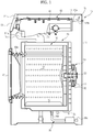
- the washing machine in accordance with an includes a main body 10 forming the external appearance of the washing machine, a tub 20 suspended within the main body 10 to contain water, a drum 30 rotatably installed within the tub 20, a door 40 to open and close a laundry inlet 10a provided to put laundry into the drum 30 therethrough, and a drum drive motor 50 installed on the rear surface of the tub 20 and generating rotary force to rotate the drum 30.
- the laundry within the drum 30 is raised upward and then fallen downward and is thus washed using a difference in elevation by rotating the drum 30 by the drum drive motor 50 under the condition that the laundry is put into the drum 30 through the inlet 30a by opening the door 40.
- Communication holes 31 through which water within the tub 20 is introduced into the drum 30 are provided on the drum 30, and lifters 32 to raise the laundry upward are arranged on the inner surface of the drum 30.
- the main body 10 includes a main body frame 11 forming front, rear and both side surfaces of the main body 10, a cover frame 12 covering the upper portion of the main body frame 11, and a support bar 13 provided with one end fixed to the upper end of the front surface of the main body frame 11 and the other end fixed to the upper end of the rear surface of the main body frame 11 to support the lower surface of the cover frame 12. Further, a control panel 14 enabling a user to select operation of the washing machine is arranged at the upper portion of the front surface of the main body 10.
- a water supply device 15 to supply water to the tub 20 and a detergent supply device 60 to mix the water supplied by the water supply device 15 with a detergent and then to supply the water containing the detergent to the tub 20 are disposed at the upper portion of the inside of the main body 10.
- the water supply device 15 includes water supply pipes 15a connected to an external water supply source, water supply valves 15b to respectively open and close the water supply pipes 15a, and a water supply hose 15c connecting the detergent supply device 60 to the tub 20 to guide the water and the detergent to the tub 20.
- a drain device 16 to discharge water used for washing to the outside after washing of the laundry has been completed is disposed under the tub 20.
- the drain device 16 includes a drain pump 16a to discharge water within the tub 20, a drain pipe 16b connecting the tub 20 and the drain pump 16a to each other, and a drain hose 16c provided within one end connected to the drain pump 16a and the other end extended to the outside of the main body 10.
- the drum drive motor 50 includes a stator 51 installed on the tub 20, a rotor 52 rotating while interacting with the stator 51, and a rotary shaft 53 provided with one end installed at the rotor 52 and the other end passing through the rear surface of the tub 20 and installed at the drum 30 to rotate the drum 30 together with the rotor 52.
- the detergent supply device 60 may supply detergents through an automatic detergent supply method and a manual detergent supply method according to user's selection, and the automatic detergent supply method is configured to additionally inject a detergent according to user's need.
- the control panel 14 includes a manual supply selection button 14a to select one of the detergent supply methods and an additional detergent button 14b to additionally inject the detergent, as shown in FIGS. 2 and 3 . Therefore, the user may select one of the detergent supply methods through the manual supply selection button 14a and additionally inject the detergent through the additional detergent button 14b.
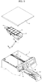
- the detergent supply device 60 includes a detergent housing 61 installed within the main body 10, a housing cover 62 installed to cover the upper portion of the detergent housing 61, a detergent accommodation box 63 movably installed within a space formed by the detergent housing 61 and the housing cover 62 to contain detergents therein, an accommodation part cover 64 covering the detergent accommodation box 63 to prevent the detergents within the detergent accommodation box 63 from overflowing during transfer of the detergent accommodation box 63, and water supply guides 66 and 67 to mix water with the detergents.
- the detergent housing 61 is provided with an accommodation space 61a in which the detergent accommodation box 63 is accommodated, and is fixed within the main body 10 such that the front surface and the upper surface of the detergent housing 61 are opened to install the detergent accommodation box 63 and the water supply guides 66 and 67.
- a connection part 61 b connected to the water supply hose 15c to supply the detergent and water to the tub 20 is provided at the lower portion of the front surface of the detergent housing 61.
- the front end of the detergent housing 61 is fixed to one side of the control panel 14 disposed at the upper portion of the front surface of the main body 10.
- An opening 14c through which the detergent accommodation box 63 is retracted into and extracted from the detergent housing 61 is provided at one side of the control panel 14.
- a sensor 70 to detect whether or not the detergent accommodation box 63 is completely retracted into the detergent housing 61 is disposed at the rear surface of the detergent housing 61, and a sensing part 632a disposed on the sensor 70 when the detergent accommodation box 63 is completely retracted into the detergent housing 61 is formed at the rear end of the detergent accommodation box 63.
- the sensor 70 may be a magnet sensor which senses a magnetic field, and a magnet is disposed in the sensing part 632.
- a support member 17 to support the rear end of the detergent housing 61 is installed on the main body 10.
- the support member 17 is provided with one end installed on the support bar 13 and the other end fixed to the upper end of one side of the main body frame 11, and the middle portion of the support member 17 is bent downward to support the lower surface of the detergent housing 61 so that the lower surface of the rear portion of the detergent housing 61 is supported by the upper surface of the support member 17.
- Reinforcing ribs 13a to reinforce the support bar 13 protrude upward from both sides of the support bar 13, and a hanging part 17a bent upward to be hang on the reinforcing rib 13a is provided at one end of the support member 17 installed on the support bar 13. Therefore, the end of the support member 17 is fixed to the support bar 13 through a screw under the condition that the hanging part 17a is hang on the reinforcing rib 13a, and the other end of the support member 17 is fixed to the upper end of the side surface of the main body frame 11 through a screw.
- the housing cover 62 is installed to cover the upper portion of the detergent housing 61 through a snap-fit connection method.
- a plurality of hooks 62a is provided at the edge of the housing cover 62, and a protruding part 61 c which protrudes outward is provided along the upper end of the detergent housing 61.
- the detergent accommodation box 63 includes a front cover 631 forming a portion of the front surface of the washing machine, and a tray 632 installed at the rear of the front cover 631 to be movable within the accommodation space 61 a of the detergent housing 61 and provided with detergent accommodation parts 632b, 632c, 632d and 632e in which detergents to be supplied are respectively stored.
- the tray 632 is formed of a transparent material to enable a user to easily observe the inside of the tray 632, and the inside of the tray 632 is divided into automatic detergent accommodation parts 632b and 632c in which a detergent to be automatically supplied is accommodated and manual detergent accommodation parts 632d and 632e in which a detergent to be manually supplied is accommodated.
- the automatic detergent accommodation parts 632b and 632c include a main detergent accommodation part 632b to automatically supply a liquid main detergent and a rinse accommodation part 632c to automatically supply a liquid fabric rinse, and the manual detergent accommodation parts 632d and 632e include a powdery detergent accommodation part 632d to supply a powdery detergent and a bleach accommodation part 632e to supply a bleach.
- a large amount of the main detergent and a large amount of the fabric rinse are injected into the main detergent accommodation part 632b and the rinse accommodation part 632c of the automatic detergent accommodation parts 632b and 632c so as to execute washing plural times, and are partially used whenever washing of the laundry is carried out.
- washing of laundry is repeated until the detergent and the fabric rinse accommodated in the main detergent accommodation part 632b and the rinse accommodation part 632c are exhausted without injection of the main detergent or the fabric rinse whenever washing of laundry is carried out, and thus use of the washing machine is convenient.
- the main detergent accommodation part 632b accommodates 1.9l of the liquid detergent in the case of a large-size washing machine and accommodates 1.5 liter of the liquid detergent in the case of a medium/small-size washing machine
- the rinse accommodation part 632 accommodates 1.5 liter of the fabric rinse in the case of a large-size washing machine and accommodates 0.5 liter of the fabric rinse in the case of a medium/small-size washing machine.
- the front cover 631 includes a bracket part 631 a extended rearward from the rear surface thereof.
- the bracket part 631 a is connected to the front portion of the lower surface of the tray 632 and disperses force, applied to the front cover 631 when the detergent accommodation box 63 is extracted or retracted, throughout the tray 632.
- display windows 631 b and 631 c are provided at both sides of the front surface of the front cover 631, thereby enabling the user to check the heights of the main detergent and the fabric rinse respectively accommodated in the main detergent accommodation part 632b and the rinse accommodation part 632c through the display windows 631 b and 631 c.
- the two display windows 631 b and 631 c include a main detergent display window 631 b to display the height of the main detergent and a rinse display window 631 c to display the height of the fabric rinse.
- Transmission parts 632f and 632g extended vertically and connected to the rear portions of the display windows 631 b and 631 c to display the heights of the main detergent and the rinse contained in the main detergent accommodation part 632b and the rinse accommodation part 632c are provided on the front surface of the tray 632.
- the tray 632 is formed of a transparent material, and thus the transmission parts 632f and 632g are formed of the transparent material. Therefore, a user located in front of the front cover 631 may observe the heights of the main detergent and the fabric rinse contained in the tray 632 through the display windows 631 b and 631c and the transmission parts 632f and 632g.
- the lower surface of the front portion of the tray 632 is downward inclined toward detergent discharge parts 632k, which will be described later, to guide the main detergent and the fabric rinse to the detergent discharge parts 632k. That is, a region of the lower surface of the tray 632 located in front of the detergent discharge parts 632k is downward inclined backwardly toward the detergent discharge parts 632k, and a region of the lower surface of the tray 632 located at the rear of the detergent discharge parts 632k is downward inclined forwardly toward the detergent discharge parts 632k.
- two detergent guide grooves 632h and 632i respectively connected to the lower portions of the two transmission parts 632f and 632g are provided on the lower surfaces of the main detergent accommodation part 632b and the rinse accommodation part 632c of the tray 632, as shown in FIG. 5 .
- the lower surfaces of the detergent guide grooves 632h and 632i are extended to have heights corresponding to the lowest portions of the inner lower surfaces of the main detergent accommodation part 632b and the rinse accommodation part 632c, thereby enabling the heights of the liquid detergent and the fabric rinse contained in the tray 632 to be precisely displayed through the display windows 631 b and 631 c.
- the accommodation part cover 64 is formed of a transparent material to allow a user to easily observe the detergents contained in the tray 63, and covers the upper portions of the main detergent accommodation part 632b and the rinse accommodation part 632c to accommodate the liquid detergent and the fabric rinse to prevent the liquid main detergent and fabric rinse from being dried. Further, the accommodation part cover 64 serves to prevent the liquid detergent and fabric rinse from overflowing the tray 632 during transfer of the detergent accommodation box 63.
- a main detergent inlet 64a and a rinse inlet 64b through which the liquid main detergent and the fabric rinse are injected into the main detergent accommodation part 632b and the rinse accommodation part 632c are provided in parallel at the front end of the accommodation part cover 64, and a rotating cover 65 to open and close the main detergent inlet 64a and the rinse inlet 64b is installed on the accommodation part cover 64.
- the rotating cover 65 is formed of a transparent material in the same manner as the accommodation part cover 64, and hinge parts 65a provided at both sides of the rotating cover 65 are rotatably connected to hinge protrusions 64f provided at both sides of the accommodation part cover 64 so that the rotating cover 65 is rotated to simultaneously open and close the main detergent inlet 64a and the rinse inlet 64b.
- a recess 64g to allow a user to easily apply force to the rotating cover 65 to rotate the rotating cover 65 is provided at one side of the rinse inlet 64b of the tray 632.
- a powdery detergent inlet 64c through which the powdery detergent is injected into the powdery detergent accommodation part 632d and a bleach inlet 64d through which the bleach is injected into the bleach accommodation part 632e are provided on the accommodation part cover 64 at the rear of the rinse inlet 64b. Since the bleach inlet 64d has a very small width in terms of the arrangement structure of the detergent accommodation parts 632b, 632c, 632d and 632e, an inclined guide 64e which is downward inclined toward the bleach inlet 64d is formed adjacent to the bleach inlet 64d of the accommodation part cover 64.
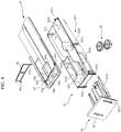
- the detergent discharge parts 632k extended into a hollow cylindrical shape to form detergent discharge holes 632j are respectively provided on the lower surfaces of the main detergent accommodation part 632b and the rinse accommodation part 632c, and the detergent supply device 60 includes two valve units 68 to selectively discharge the liquid main detergent and fabric rinse through the two detergent discharge holes 632j and two valve drive devices 69 to independently operate the two valve units 68.
- the valve unit 68 includes a valve 681 ascending and descending to open and close the detergent discharge part 632k, an ascending/descending guide 682 to guide ascending and descending of the valve 681, a valve cap 683 to install the ascending/descending guide 682 on the detergent discharge part 632k, and an elastic member 684 to elastically support the valve 681.
- the ascending/descending guide 682 is formed in a hollow cylindrical shape and is provided with a temporary storage space 682a to temporarily accommodate the liquid main detergent or fabric rinse, and a guide hole 682b in which the valve 681 is installed to be capable of ascending and descending, and a first valve hole 682c located adjacent to the guide hole 682b to pass the liquid main detergent or fabric rinse.
- a support rib 682d protruding in the radial direction is provided on the outer circumferential surface of the lower end of the ascending/descending guide 682, and is inserted into a gap between the lower end of the detergent discharge part 632k and the inner surface of the valve cap 683 during a process of coupling the valve cap 683 with the detergent discharge part 632k, thereby maintaining a state in which the ascending/descending guide 682 is installed on the detergent discharge part 632k.
- the valve cap 683 includes a second valve hole 683a to discharge the detergent temporarily stored in the temporary storage space 682a of the ascending/descending guide 682 to the inside of the detergent housing 61, and is connected to the detergent discharge part 632k of the tray 632 through a screw connection method.
- the valve 681 includes a valve shaft 681 a installed within the guide hole 682b to be capable of ascending and descending, a first valve part 681 b formed of a elastically deformable material, such as rubber, and disposed above the value shaft 681 a to open and close the first valve hole 682c according to ascending and descending of the valve 681, and a second valve part 681c formed integrally with the lower end of the valve shaft 681a to open and close the second valve hole 683a according to ascending and descending of the valve 681.
- the lower surface of the second valve part 681c is supported by a cam 691 which will be described later so that the valve 681 ascends and descends by force transmitted from the cam 691 through the second valve part 681c.
- the elastic member 684 is provided with one end supported by the lower surface of a portion of the ascending/descending guide 682 adjacent to the guide hole 682b and the other end supported by the upper surface of the second valve part 681c, and elastically supports the valve 681 in the downward direction.
- the two valve drive devices 69 are installed at both sides of the detergent housing 61, and each of the two valve drive devices 69 includes the cam 691 rotated to ascend and descend the valve 681 and a detergent supply motor 692 to rotate the cam 691.
- the cam 691 has a fan-shaped cross section and is rotated by the detergent supply motor 692 to ascend and descent the valve 681 based on the rotating angel thereof.
- the cam 691 as shown in FIG. 6 , is disposed under the valve 681 of the detergent accommodation box 63 retracted into the detergent housing 61 within the detergent housing 61, and applies force to the valve 681 through the lower end of the valve 681, i.e., the lower surface of the second valve part 681 c.
- the detergent supply motor 692 is installed at each of motor installation parts 61 d provided at both sides of the lower portion of the detergent housing 61, and a rotary shaft 692a of the detergent supply motor 692 is connected to the cam 691 disposed within the detergent housing 61 through a shaft installation hole 61 e provided on the detergent housing 61 and transmits rotary force to the cam 691.
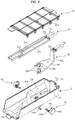
- the water supply guides 66 and 67 include an automatic water supply guide 66 connected to the water supply pipes 15a and disposed under the detergent accommodation box 63 retracted into the detergent housing 61, and a manual water supply guide 67 installed on the lower surface of the housing cover 62 and disposed on the accommodation part cover 64 to supply water to the powdery detergent accommodation part 632d and the bleach accommodation part 632e of the manual detergent accommodation parts 632d and 632e.
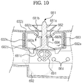
- the automatic water supply guide 66 is configured to guide water to the lower portion of the detergent accommodation box 63 retracted into the detergent housing 61 and to spray water toward the lower ends of the valve units 68 disposed under the detergent accommodation box 63.
- the automatic water supply guide 66 includes automatic water supply ports 66a provided at the rear end thereof and connected to the water supply pipes 15a, an extension part 66b extended downward to guide water in the downward direction, and a spray part 66c extended forward from the lower end of the extension part 66b and provided with spray holes 66d formed at the front end thereof to spray water toward the lower ends of the valve units 68.
- Shields 66e disposed in an arc shape around the valve caps 683 to prevent water from being splashed backward are formed on the upper surface of the spray part 66c.
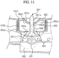
- the manual water supply guide 67 includes manual water supply ports 67a provided at the rear end thereof and connected to the water supply pipes 15a, and a powdery detergent water supply channel 67b and a bleach water supply channel 67c, upper surfaces of which are opened.
- the manual water supply guide 67 is fixed to the lower surface of the housing cover 62 through heat fusion, etc., and thus the upper surfaces of the powdery detergent water supply channel 67b and the bleach water supply channel 67c are closed.
- Water supply holes 67d to supply water to powdery detergent accommodation part 632d and the bleach accommodation part 632e through the lower surface of the manual water supply guide 67 are provided on the lower surface of the manual water supply guide 67 at positions corresponding to the powdery detergent accommodation part 632d and the bleach accommodation part 632e.
- the spray holes 66d of the automatic water supply guide 66 spray water.
- the sprayed water is mixed with the detergent discharged through the second valve hole 683a, and is then supplied to the tub 20 through the water supply hose 15c connected to the detergent housing 61.
- the spray holes 66d are configured to spray water toward the second valve part 681 c of the valve 681, the second valve hole 683a and the cam 691, the second valve part 681 c, the second valve hole 683a and the cam 691 are washed by the water sprayed from the spray holes 66d, and thus remaining of the detergent on the second valve part 681c, the second valve hole 683a and the cam 691 is prevented. Therefore, malfunction of the valves 681, generated if the liquid main detergent or fabric rinse remaining on the second valve parts 681 c, the second valve holes 683a and the cams 691 is solidified, may be prevented.
- the tray 632 is not limited thereto.
- the tray is not limited thereto.
- the tray 632' may include only a main detergent accommodation part 632a' and a rinse accommodation part 632b' without components corresponding to the powdery detergent accommodation part and the bleach detergent accommodation part, and the detergent supply device 60 includes a pair of valve units 68, a pair of valve drive device 69 and a water supply guide 66' to supply only a main detergent and a fabric rinse through the automatic detergent supply method.
- the detergent housing 61 may be installed within the main body frame 11 by fixing a coupling part 61f integrally extended from the rear surface of the detergent housing 61 to the rear end of the main body frame 11 through a fastening member, such as a screw.
- a user operates the control panel 14 to execute washing under the condition that the manual supply selection button 14a is not selected.
- the water supply valves 15b are controlled so as to supply water only to the automatic water supply guide 66, and the detergent supply motors 692 are driven to rotate the cams 691.
- water is sprayed through the spray holes 66d provided at the front end of the automatic water supply guide 66 and a portion of the main detergent accommodated in the main detergent accommodation part 632b is discharged through the second valve hole 683a, simultaneously.
- the water and the main detergent are mixed within the detergent housing 61, and are then supplied to the tub 20 through the water supply hose 15c.
- the user extracts the detergent accommodation box 63 from the detergent housing 61, puts the powdery detergent into the powdery detergent accommodation part 632d through the powdery detergent inlet 64c, and then retracts the detergent accommodation box 63 into the detergent housing 61.
- the water supply valves 15b are controlled so as to supply water only to the powdery detergent water supply channel 67b of the manual water supply guide 67. Therefore, water is supplied to the powdery detergent accommodation part 632d through the water supply holes 67d provided on the manual water supply guide 67 and the powdery detergent inlet 64c, is mixed with the powdery detergent accommodated within the powdery detergent accommodation part 632d, and is then supplied to the tub 20 through the water supply hose 15c.
- a washing machine in accordance with an embodiment has a detergent supply device which supplies a detergent through an automatic detergent supply method or a manual detergent supply method according to user's section, thereby using various types of detergent.
- the washing machine removes a liquid detergent remaining on valves by spraying water toward the valves through an automatic water supply guide, thereby preventing malfunction of the valves generated when the liquid detergent remaining on valve units is dried and solidified.
Landscapes
- Engineering & Computer Science (AREA)
- Textile Engineering (AREA)
- Mechanical Engineering (AREA)
- Detail Structures Of Washing Machines And Dryers (AREA)
- Washing And Drying Of Tableware (AREA)
Applications Claiming Priority (2)
| Application Number | Priority Date | Filing Date | Title |
|---|---|---|---|
| KR1020110004383A KR20120082989A (ko) | 2011-01-17 | 2011-01-17 | 세탁기 |
| EP12150853.5A EP2476792B1 (fr) | 2011-01-17 | 2012-01-12 | Machine à laver |
Related Parent Applications (2)
| Application Number | Title | Priority Date | Filing Date |
|---|---|---|---|
| EP12150853.5A Division-Into EP2476792B1 (fr) | 2011-01-17 | 2012-01-12 | Machine à laver |
| EP12150853.5A Division EP2476792B1 (fr) | 2011-01-17 | 2012-01-12 | Machine à laver |
Publications (2)
| Publication Number | Publication Date |
|---|---|
| EP3243952A1 true EP3243952A1 (fr) | 2017-11-15 |
| EP3243952B1 EP3243952B1 (fr) | 2019-04-24 |
Family
ID=45495780
Family Applications (2)
| Application Number | Title | Priority Date | Filing Date |
|---|---|---|---|
| EP17174852.8A Active EP3243952B1 (fr) | 2011-01-17 | 2012-01-12 | Machine à laver |
| EP12150853.5A Active EP2476792B1 (fr) | 2011-01-17 | 2012-01-12 | Machine à laver |
Family Applications After (1)
| Application Number | Title | Priority Date | Filing Date |
|---|---|---|---|
| EP12150853.5A Active EP2476792B1 (fr) | 2011-01-17 | 2012-01-12 | Machine à laver |
Country Status (5)
| Country | Link |
|---|---|
| US (4) | US9834879B2 (fr) |
| EP (2) | EP3243952B1 (fr) |
| KR (1) | KR20120082989A (fr) |
| CN (2) | CN107574629B (fr) |
| TR (1) | TR201910796T4 (fr) |
Cited By (1)
| Publication number | Priority date | Publication date | Assignee | Title |
|---|---|---|---|---|
| EP3617374A1 (fr) * | 2018-08-30 | 2020-03-04 | Electrolux Appliances Aktiebolag | Appareil de blanchissage ayant un tiroir convivial |
Families Citing this family (35)
| Publication number | Priority date | Publication date | Assignee | Title |
|---|---|---|---|---|
| KR20130081114A (ko) | 2012-01-06 | 2013-07-16 | 삼성전자주식회사 | 세제공급장치 및 이를 가지는 세탁기 |
| EP2746446A1 (fr) * | 2012-12-21 | 2014-06-25 | Electrolux Home Products Corporation N.V. | Structure de support d'appareil de traitement de linge à tambour rotatif et appareil de traitement de linge à tambour rotatif comprenant ladite structure |
| CN103485133B (zh) * | 2013-06-26 | 2016-05-25 | 无锡小天鹅股份有限公司 | 洗衣机及其洗涤剂抽斗组件 |
| CN107354677B (zh) | 2013-07-03 | 2020-01-24 | 三星电子株式会社 | 洗涤剂供给装置以及具有该装置的洗衣机 |
| KR101343712B1 (ko) * | 2013-07-16 | 2013-12-20 | 김학열 | 드럼세탁기의 세제공급통 |
| ITTO20130693A1 (it) * | 2013-08-14 | 2015-02-15 | Elbi Int Spa | Struttura di cassetto per l'erogazione dosata di almeno un agente di lavaggio in una macchina lavatrice, in particolare una macchina lavabiancheria. |
| KR102210011B1 (ko) * | 2013-09-05 | 2021-02-01 | 삼성전자주식회사 | 세탁기 및 그 제어방법 |
| WO2015034284A1 (fr) * | 2013-09-05 | 2015-03-12 | 삼성전자주식회사 | Machine à laver et son procédé de commande |
| EP3047063B1 (fr) * | 2013-09-16 | 2018-06-06 | Arçelik Anonim Sirketi | Appareil de lavage comprenant une unité de rinçage à agents de nettoyage |
| CN103603172B (zh) * | 2013-12-02 | 2016-08-17 | 代傲电子控制(南京)有限公司 | 一种处理剂添加装置及洗衣机 |
| EP3114270B1 (fr) * | 2014-03-04 | 2020-04-29 | LG Electronics Inc. | Lave-linge |
| KR102296969B1 (ko) * | 2014-03-21 | 2021-09-02 | 삼성전자주식회사 | 세탁기 |
| CN104300767A (zh) | 2014-09-05 | 2015-01-21 | 胜美达电机(香港)有限公司 | 电源模块及其制造方法 |
| CN105624982B (zh) * | 2014-10-30 | 2019-08-09 | 青岛海尔智能技术研发有限公司 | 洗衣机及其控制方法 |
| CN106319872B (zh) * | 2015-06-30 | 2018-08-28 | 无锡小天鹅股份有限公司 | 用于洗衣机的洗衣粉盒、洗衣机的上盖组件及洗衣机 |
| USD788390S1 (en) * | 2015-07-02 | 2017-05-30 | Samsung Electronics Co., Ltd. | Detergent container for washing machine |
| USD788391S1 (en) * | 2015-07-02 | 2017-05-30 | Samsung Electronics Co., Ltd. | Detergent container for washing machine |
| CN106930058B (zh) * | 2015-12-31 | 2019-11-01 | 青岛海尔洗涤电器有限公司 | 一种洗涤剂投放器的安装结构 |
| CN105463788A (zh) * | 2015-12-31 | 2016-04-06 | 无锡小天鹅股份有限公司 | 洗衣机的分配器盒组件和具有其的洗衣机 |
| CN106930059B (zh) * | 2015-12-31 | 2019-11-08 | 青岛海尔滚筒洗衣机有限公司 | 一种洗涤剂投放器及洗衣机 |
| CN105442266A (zh) * | 2015-12-31 | 2016-03-30 | 无锡小天鹅股份有限公司 | 洗衣机的分配器盒组件和具有其的洗衣机 |
| CN105442264A (zh) * | 2015-12-31 | 2016-03-30 | 无锡小天鹅股份有限公司 | 洗衣机的分配器盒组件和具有其的洗衣机 |
| KR102512289B1 (ko) * | 2016-05-30 | 2023-03-22 | 엘지전자 주식회사 | 의류처리장치 |
| USD828662S1 (en) * | 2016-06-08 | 2018-09-11 | Lg Electronics Inc. | Detergent inlet for washing machine |
| JP6945597B2 (ja) * | 2016-07-19 | 2021-10-06 | 日立グローバルライフソリューションズ株式会社 | 洗濯機 |
| CN106263635B (zh) * | 2016-08-23 | 2019-07-09 | 郭玲玲 | 一种内通风的多层式鞋柜 |
| CN106308111B (zh) * | 2016-08-23 | 2019-07-09 | 新昌县鑫鹏机械有限公司 | 一种通风效果好的鞋柜 |
| CN106263637B (zh) * | 2016-08-23 | 2018-12-18 | 江苏西盛家具实业有限公司 | 一种多功能鞋柜 |
| CN108930142B (zh) * | 2017-05-27 | 2021-03-16 | 青岛海尔洗涤电器有限公司 | 一种洗涤添加剂盒及洗衣机 |
| EP3617379B1 (fr) | 2018-08-30 | 2021-08-04 | Electrolux Appliances Aktiebolag | Appareil de traitement du linge comprenant un tiroir amélioré |
| KR20210026229A (ko) * | 2019-08-29 | 2021-03-10 | 엘지전자 주식회사 | 저장 용기 및 이를 포함하는 의류 처리 장치 |
| KR20210026227A (ko) * | 2019-08-29 | 2021-03-10 | 엘지전자 주식회사 | 지지 부재 및 이를 포함하는 의류 처리 장치 |
| KR20210131758A (ko) | 2020-04-24 | 2021-11-03 | 엘지전자 주식회사 | 의류처리장치 |
| KR20220041368A (ko) * | 2020-09-25 | 2022-04-01 | 엘지전자 주식회사 | 의류처리장치 |
| WO2023286358A1 (fr) * | 2021-07-12 | 2023-01-19 | 日立グローバルライフソリューションズ株式会社 | Lave-linge |
Citations (9)
| Publication number | Priority date | Publication date | Assignee | Title |
|---|---|---|---|---|
| US20030145633A1 (en) * | 2002-02-06 | 2003-08-07 | Merkle Scott A. | Dual use detergent dispenser |
| EP1884584A2 (fr) * | 2006-07-31 | 2008-02-06 | Indesit Company S.p.A. | Machine à laver, en particulier lave-linge, comprenant un distributeur d'agents de lavage de grande capacité |
| US20080235880A1 (en) * | 2007-03-31 | 2008-10-02 | Lg Electronics Inc. | Washing machine |
| EP2003237A1 (fr) * | 2007-06-12 | 2008-12-17 | Electrolux Home Products Corporation N.V. | Distributeur de produits détergents et similaires pour un lave-linge |
| WO2009142355A1 (fr) * | 2008-05-23 | 2009-11-26 | Lg Electronics Inc. | Distributeur et machine à laver |
| US20100000586A1 (en) * | 2008-07-01 | 2010-01-07 | Whirlpool Corporation | Household cleaning appliance with a single water flow path for both non-bulk and bulk dispensing |
| US20100000264A1 (en) * | 2008-07-01 | 2010-01-07 | Whirlpool Corporation | Method for converting a household cleaning appliance with a non-bulk dispensing system to a household cleaning appliance with a bulk dispensing system |
| EP2251480A1 (fr) * | 2009-05-11 | 2010-11-17 | Electrolux Home Products Corporation N.V. | Machine à laver |
| US20110186098A1 (en) * | 2008-10-07 | 2011-08-04 | Bsh Bosch Und Siemens Hausgerate Gmbh | Water-carrying household appliance having an automatic dosing system, and method for automatic dosing |
Family Cites Families (40)
| Publication number | Priority date | Publication date | Assignee | Title |
|---|---|---|---|---|
| US2122216A (en) * | 1936-06-15 | 1938-06-28 | Joseph M Seawell | Bulk material dispensing device |
| US2887255A (en) * | 1956-06-22 | 1959-05-19 | Dole Valve Co | Liquid measuring device |
| US3089618A (en) * | 1960-08-30 | 1963-05-14 | Courtesy Products Corp | Liquid measuring and dispensing machine |
| US3144031A (en) * | 1962-04-17 | 1964-08-11 | Westinghouse Electric Corp | Detergent dispensing apparatus for automatic washing machines |
| DE1814008A1 (de) * | 1968-12-06 | 1970-07-02 | Siemens Elektrogeraete Gmbh | Gehaeuse fuer eine Haushaltmaschine |
| KR870002303Y1 (ko) | 1985-03-25 | 1987-06-30 | 강재원 | 변기용 후레쉬 밸브의 몸체 간격 조절장치 |
| DE3605238A1 (de) * | 1986-02-19 | 1987-08-20 | Bauknecht Hausgeraete | Waschautomat |
| DE8701540U1 (fr) * | 1987-02-02 | 1987-07-02 | Westfalia Separator Ag, 4740 Oelde, De | |
| JP3058309B2 (ja) | 1994-08-05 | 2000-07-04 | シャープ株式会社 | 洗剤投入装置付き洗濯機 |
| KR0149912B1 (ko) * | 1995-06-14 | 1999-05-15 | 김광호 | 세탁기의 세제용해장치 |
| US5870906A (en) * | 1996-04-03 | 1999-02-16 | Denisar; Richard A. | Automatic dispensing device |
| US5782109A (en) * | 1996-05-06 | 1998-07-21 | Ecolab Inc. | Dispenser |
| US6036056A (en) * | 1997-05-05 | 2000-03-14 | Lee; Kuo-Chou | Automatic soap dispensing device |
| IT1295907B1 (it) * | 1997-10-31 | 1999-05-28 | T & P Spa | Un complesso perfezionato per la fornitura selettiva di agenti di lavaggio ad una vasca di lavoro di una macchina di lavaggio |
| DE19822430C1 (de) * | 1998-05-19 | 2000-02-10 | Hassia Verpackung Ag | Dosierventil an Dosierpumpen |
| US6434977B1 (en) * | 2000-10-06 | 2002-08-20 | Ark-Les Corporation | Automatic laundry aid dispenser for washing machine |
| KR100781247B1 (ko) | 2001-07-06 | 2007-11-30 | 엘지전자 주식회사 | 세탁기의 액체세제 자동 투입장치 |
| KR100830488B1 (ko) | 2001-07-24 | 2008-05-21 | 엘지전자 주식회사 | 드럼세탁기의 세제 공급장치 |
| US6588724B2 (en) * | 2001-08-15 | 2003-07-08 | Jetec Company | On-off valves for high pressure fluids |
| CN100383327C (zh) | 2002-07-05 | 2008-04-23 | 乐金电子(天津)电器有限公司 | 洗衣机的液体洗涤剂自动投入装置 |
| US7651015B2 (en) * | 2004-02-13 | 2010-01-26 | Intelligent Coffee Company, Llc | Liquid concentrate/extract beverage dispenser with replaceable concentrate/extract cartridge |
| EP1568815B1 (fr) * | 2004-02-27 | 2011-03-30 | Whirlpool Corporation | Machine à laver avec distributeur de détergent |
| KR101082564B1 (ko) * | 2004-04-14 | 2011-11-10 | 엘지전자 주식회사 | 세탁기의 디스펜서 |
| CN1746409A (zh) | 2004-09-08 | 2006-03-15 | 乐金电子(天津)电器有限公司 | 洗衣机的洗涤剂放入装置 |
| KR101186320B1 (ko) * | 2005-12-06 | 2012-09-27 | 엘지전자 주식회사 | 드럼 세탁기의 세제 투입장치 |
| DE102006012283B3 (de) * | 2006-03-15 | 2007-03-01 | Miele & Cie. Kg | Waschmaschine mit externer Waschmittelbeschickung |
| DE102006018599A1 (de) * | 2006-04-21 | 2007-10-25 | Schaeffler Kg | Zwangssteuerung für ein Hubventil einer Brennkraftmaschine |
| CN101168905A (zh) * | 2006-10-23 | 2008-04-30 | 南京乐金熊猫电器有限公司 | 洗涤装置的顶板设置结构 |
| DE102007014425A1 (de) * | 2007-03-22 | 2008-09-25 | Henkel Ag & Co. Kgaa | Bewegliches Dosiersystem zur Abgabe von fließ- oder streufähigen Zubereitungen |
| US8066157B2 (en) * | 2007-07-16 | 2011-11-29 | Rodney Laible | Dispensing and/or dosing system including an improved throat plug assembly |
| DE102007039666B3 (de) * | 2007-08-22 | 2008-09-11 | Miele & Cie. Kg | Waschmaschine mit externer Waschmittelbeschickung |
| KR100968595B1 (ko) | 2008-02-01 | 2010-07-08 | 애경산업(주) | 분말 세제 배출 장치 |
| US8196441B2 (en) * | 2008-07-01 | 2012-06-12 | Whirlpool Corporation | Household cleaning appliance with a dispensing system operable between a single use dispensing system and a bulk dispensing system |
| CN201386213Y (zh) * | 2008-12-29 | 2010-01-20 | 博西威家用电器有限公司 | 家用电器的进水阀系统 |
| KR101621533B1 (ko) | 2009-01-05 | 2016-05-16 | 동부대우전자 주식회사 | 드럼세탁기용 세제투입장치 |
| KR20100120047A (ko) | 2009-05-04 | 2010-11-12 | 엘지전자 주식회사 | 세탁 장치용 세제함 |
| CN101886324B (zh) | 2010-07-07 | 2011-11-23 | 南京乐金熊猫电器有限公司 | 洗衣剂分配盒 |
| KR20120043214A (ko) * | 2010-10-26 | 2012-05-04 | 삼성전자주식회사 | 세탁기 |
| EP2597190B1 (fr) * | 2011-11-22 | 2015-01-07 | Miele & Cie. KG | Lave-linge doté d'un dispositif d'introduction et d'un récipient insérable |
| CN202744828U (zh) * | 2012-07-27 | 2013-02-20 | 南京乐金熊猫电器有限公司 | 液体类洗涤剂自动投放装置 |
-
2011
- 2011-01-17 KR KR1020110004383A patent/KR20120082989A/ko active Search and Examination
-
2012
- 2012-01-11 US US13/348,146 patent/US9834879B2/en active Active
- 2012-01-12 EP EP17174852.8A patent/EP3243952B1/fr active Active
- 2012-01-12 TR TR2019/10796T patent/TR201910796T4/tr unknown
- 2012-01-12 EP EP12150853.5A patent/EP2476792B1/fr active Active
- 2012-01-17 CN CN201710971806.9A patent/CN107574629B/zh active Active
- 2012-01-17 CN CN201210023209.0A patent/CN102587088B/zh active Active
-
2017
- 2017-10-25 US US15/792,998 patent/US11242639B2/en active Active
-
2021
- 2021-12-30 US US17/565,874 patent/US11649579B2/en active Active
-
2023
- 2023-04-07 US US18/132,223 patent/US20230243084A1/en active Pending
Patent Citations (9)
| Publication number | Priority date | Publication date | Assignee | Title |
|---|---|---|---|---|
| US20030145633A1 (en) * | 2002-02-06 | 2003-08-07 | Merkle Scott A. | Dual use detergent dispenser |
| EP1884584A2 (fr) * | 2006-07-31 | 2008-02-06 | Indesit Company S.p.A. | Machine à laver, en particulier lave-linge, comprenant un distributeur d'agents de lavage de grande capacité |
| US20080235880A1 (en) * | 2007-03-31 | 2008-10-02 | Lg Electronics Inc. | Washing machine |
| EP2003237A1 (fr) * | 2007-06-12 | 2008-12-17 | Electrolux Home Products Corporation N.V. | Distributeur de produits détergents et similaires pour un lave-linge |
| WO2009142355A1 (fr) * | 2008-05-23 | 2009-11-26 | Lg Electronics Inc. | Distributeur et machine à laver |
| US20100000586A1 (en) * | 2008-07-01 | 2010-01-07 | Whirlpool Corporation | Household cleaning appliance with a single water flow path for both non-bulk and bulk dispensing |
| US20100000264A1 (en) * | 2008-07-01 | 2010-01-07 | Whirlpool Corporation | Method for converting a household cleaning appliance with a non-bulk dispensing system to a household cleaning appliance with a bulk dispensing system |
| US20110186098A1 (en) * | 2008-10-07 | 2011-08-04 | Bsh Bosch Und Siemens Hausgerate Gmbh | Water-carrying household appliance having an automatic dosing system, and method for automatic dosing |
| EP2251480A1 (fr) * | 2009-05-11 | 2010-11-17 | Electrolux Home Products Corporation N.V. | Machine à laver |
Cited By (2)
| Publication number | Priority date | Publication date | Assignee | Title |
|---|---|---|---|---|
| EP3617374A1 (fr) * | 2018-08-30 | 2020-03-04 | Electrolux Appliances Aktiebolag | Appareil de blanchissage ayant un tiroir convivial |
| WO2020043624A1 (fr) * | 2018-08-30 | 2020-03-05 | Electrolux Appliances Aktiebolag | Appareil de lessive à tiroir facile à utiliser |
Also Published As
| Publication number | Publication date |
|---|---|
| US11242639B2 (en) | 2022-02-08 |
| US9834879B2 (en) | 2017-12-05 |
| EP2476792A3 (fr) | 2014-08-13 |
| US11649579B2 (en) | 2023-05-16 |
| US20180044840A1 (en) | 2018-02-15 |
| US20230243084A1 (en) | 2023-08-03 |
| CN102587088A (zh) | 2012-07-18 |
| EP2476792B1 (fr) | 2018-01-03 |
| US20220120016A1 (en) | 2022-04-21 |
| US20120180533A1 (en) | 2012-07-19 |
| CN107574629A (zh) | 2018-01-12 |
| EP2476792A2 (fr) | 2012-07-18 |
| EP3243952B1 (fr) | 2019-04-24 |
| KR20120082989A (ko) | 2012-07-25 |
| TR201910796T4 (tr) | 2019-08-21 |
| CN102587088B (zh) | 2017-11-21 |
| CN107574629B (zh) | 2021-01-01 |
Similar Documents
| Publication | Publication Date | Title |
|---|---|---|
| US20230243084A1 (en) | Washing machine | |
| EP3239386B1 (fr) | Machine à laver | |
| CA2943973C (fr) | Machine a laver | |
| US20160069012A1 (en) | Method for controlling a laundry treating apparatus | |
| EP3202968B1 (fr) | Appareil de traitement de vêtements | |
| EP3287556B1 (fr) | Machine à laver | |
| EP3056599B1 (fr) | Dispositif de traitement de vêtement | |
| US20170137985A1 (en) | Washing machine | |
| KR100873681B1 (ko) | 탑 로드형 세탁기 | |
| EP3633093B1 (fr) | Appareil de traitement de linge | |
| CN111093455B (zh) | 洗碗机 | |
| EP3569756B1 (fr) | Lave-linge | |
| KR101914271B1 (ko) | 세탁기 | |
| US20230228026A1 (en) | Detergent supply apparatus and washing machine having same | |
| KR102035473B1 (ko) | 세탁기 | |
| KR102350236B1 (ko) | 세탁기 | |
| KR20160107043A (ko) | 세탁물처리기기 | |
| KR20070015306A (ko) | 세탁기의 제어방법 및 제어장치 |
Legal Events
| Date | Code | Title | Description |
|---|---|---|---|
| PUAI | Public reference made under article 153(3) epc to a published international application that has entered the european phase |
Free format text: ORIGINAL CODE: 0009012 |
|
| STAA | Information on the status of an ep patent application or granted ep patent |
Free format text: STATUS: REQUEST FOR EXAMINATION WAS MADE |
|
| 17P | Request for examination filed |
Effective date: 20170607 |
|
| AC | Divisional application: reference to earlier application |
Ref document number: 2476792 Country of ref document: EP Kind code of ref document: P |
|
| AK | Designated contracting states |
Kind code of ref document: A1 Designated state(s): AL AT BE BG CH CY CZ DE DK EE ES FI FR GB GR HR HU IE IS IT LI LT LU LV MC MK MT NL NO PL PT RO RS SE SI SK SM TR |
|
| GRAP | Despatch of communication of intention to grant a patent |
Free format text: ORIGINAL CODE: EPIDOSNIGR1 |
|
| STAA | Information on the status of an ep patent application or granted ep patent |
Free format text: STATUS: GRANT OF PATENT IS INTENDED |
|
| INTG | Intention to grant announced |
Effective date: 20180529 |
|
| GRAJ | Information related to disapproval of communication of intention to grant by the applicant or resumption of examination proceedings by the epo deleted |
Free format text: ORIGINAL CODE: EPIDOSDIGR1 |
|
| STAA | Information on the status of an ep patent application or granted ep patent |
Free format text: STATUS: REQUEST FOR EXAMINATION WAS MADE |
|
| GRAP | Despatch of communication of intention to grant a patent |
Free format text: ORIGINAL CODE: EPIDOSNIGR1 |
|
| STAA | Information on the status of an ep patent application or granted ep patent |
Free format text: STATUS: GRANT OF PATENT IS INTENDED |
|
| INTC | Intention to grant announced (deleted) | ||
| INTG | Intention to grant announced |
Effective date: 20181108 |
|
| GRAS | Grant fee paid |
Free format text: ORIGINAL CODE: EPIDOSNIGR3 |
|
| GRAA | (expected) grant |
Free format text: ORIGINAL CODE: 0009210 |
|
| STAA | Information on the status of an ep patent application or granted ep patent |
Free format text: STATUS: THE PATENT HAS BEEN GRANTED |
|
| AC | Divisional application: reference to earlier application |
Ref document number: 2476792 Country of ref document: EP Kind code of ref document: P |
|
| AK | Designated contracting states |
Kind code of ref document: B1 Designated state(s): AL AT BE BG CH CY CZ DE DK EE ES FI FR GB GR HR HU IE IS IT LI LT LU LV MC MK MT NL NO PL PT RO RS SE SI SK SM TR |
|
| REG | Reference to a national code |
Ref country code: GB Ref legal event code: FG4D |
|
| REG | Reference to a national code |
Ref country code: CH Ref legal event code: EP |
|
| REG | Reference to a national code |
Ref country code: AT Ref legal event code: REF Ref document number: 1124290 Country of ref document: AT Kind code of ref document: T Effective date: 20190515 Ref country code: IE Ref legal event code: FG4D |
|
| REG | Reference to a national code |
Ref country code: DE Ref legal event code: R096 Ref document number: 602012059482 Country of ref document: DE |
|
| REG | Reference to a national code |
Ref country code: NL Ref legal event code: MP Effective date: 20190424 |
|
| REG | Reference to a national code |
Ref country code: LT Ref legal event code: MG4D |
|
| PG25 | Lapsed in a contracting state [announced via postgrant information from national office to epo] |
Ref country code: NL Free format text: LAPSE BECAUSE OF FAILURE TO SUBMIT A TRANSLATION OF THE DESCRIPTION OR TO PAY THE FEE WITHIN THE PRESCRIBED TIME-LIMIT Effective date: 20190424 |
|
| PG25 | Lapsed in a contracting state [announced via postgrant information from national office to epo] |
Ref country code: HR Free format text: LAPSE BECAUSE OF FAILURE TO SUBMIT A TRANSLATION OF THE DESCRIPTION OR TO PAY THE FEE WITHIN THE PRESCRIBED TIME-LIMIT Effective date: 20190424 Ref country code: LT Free format text: LAPSE BECAUSE OF FAILURE TO SUBMIT A TRANSLATION OF THE DESCRIPTION OR TO PAY THE FEE WITHIN THE PRESCRIBED TIME-LIMIT Effective date: 20190424 Ref country code: ES Free format text: LAPSE BECAUSE OF FAILURE TO SUBMIT A TRANSLATION OF THE DESCRIPTION OR TO PAY THE FEE WITHIN THE PRESCRIBED TIME-LIMIT Effective date: 20190424 Ref country code: PT Free format text: LAPSE BECAUSE OF FAILURE TO SUBMIT A TRANSLATION OF THE DESCRIPTION OR TO PAY THE FEE WITHIN THE PRESCRIBED TIME-LIMIT Effective date: 20190824 Ref country code: FI Free format text: LAPSE BECAUSE OF FAILURE TO SUBMIT A TRANSLATION OF THE DESCRIPTION OR TO PAY THE FEE WITHIN THE PRESCRIBED TIME-LIMIT Effective date: 20190424 Ref country code: NO Free format text: LAPSE BECAUSE OF FAILURE TO SUBMIT A TRANSLATION OF THE DESCRIPTION OR TO PAY THE FEE WITHIN THE PRESCRIBED TIME-LIMIT Effective date: 20190724 Ref country code: AL Free format text: LAPSE BECAUSE OF FAILURE TO SUBMIT A TRANSLATION OF THE DESCRIPTION OR TO PAY THE FEE WITHIN THE PRESCRIBED TIME-LIMIT Effective date: 20190424 Ref country code: SE Free format text: LAPSE BECAUSE OF FAILURE TO SUBMIT A TRANSLATION OF THE DESCRIPTION OR TO PAY THE FEE WITHIN THE PRESCRIBED TIME-LIMIT Effective date: 20190424 |
|
| PG25 | Lapsed in a contracting state [announced via postgrant information from national office to epo] |
Ref country code: LV Free format text: LAPSE BECAUSE OF FAILURE TO SUBMIT A TRANSLATION OF THE DESCRIPTION OR TO PAY THE FEE WITHIN THE PRESCRIBED TIME-LIMIT Effective date: 20190424 Ref country code: PL Free format text: LAPSE BECAUSE OF FAILURE TO SUBMIT A TRANSLATION OF THE DESCRIPTION OR TO PAY THE FEE WITHIN THE PRESCRIBED TIME-LIMIT Effective date: 20190424 Ref country code: BG Free format text: LAPSE BECAUSE OF FAILURE TO SUBMIT A TRANSLATION OF THE DESCRIPTION OR TO PAY THE FEE WITHIN THE PRESCRIBED TIME-LIMIT Effective date: 20190724 Ref country code: GR Free format text: LAPSE BECAUSE OF FAILURE TO SUBMIT A TRANSLATION OF THE DESCRIPTION OR TO PAY THE FEE WITHIN THE PRESCRIBED TIME-LIMIT Effective date: 20190725 Ref country code: RS Free format text: LAPSE BECAUSE OF FAILURE TO SUBMIT A TRANSLATION OF THE DESCRIPTION OR TO PAY THE FEE WITHIN THE PRESCRIBED TIME-LIMIT Effective date: 20190424 |
|
| REG | Reference to a national code |
Ref country code: AT Ref legal event code: MK05 Ref document number: 1124290 Country of ref document: AT Kind code of ref document: T Effective date: 20190424 |
|
| PG25 | Lapsed in a contracting state [announced via postgrant information from national office to epo] |
Ref country code: IS Free format text: LAPSE BECAUSE OF FAILURE TO SUBMIT A TRANSLATION OF THE DESCRIPTION OR TO PAY THE FEE WITHIN THE PRESCRIBED TIME-LIMIT Effective date: 20190824 |
|
| REG | Reference to a national code |
Ref country code: DE Ref legal event code: R097 Ref document number: 602012059482 Country of ref document: DE |
|
| PG25 | Lapsed in a contracting state [announced via postgrant information from national office to epo] |
Ref country code: RO Free format text: LAPSE BECAUSE OF FAILURE TO SUBMIT A TRANSLATION OF THE DESCRIPTION OR TO PAY THE FEE WITHIN THE PRESCRIBED TIME-LIMIT Effective date: 20190424 Ref country code: CZ Free format text: LAPSE BECAUSE OF FAILURE TO SUBMIT A TRANSLATION OF THE DESCRIPTION OR TO PAY THE FEE WITHIN THE PRESCRIBED TIME-LIMIT Effective date: 20190424 Ref country code: EE Free format text: LAPSE BECAUSE OF FAILURE TO SUBMIT A TRANSLATION OF THE DESCRIPTION OR TO PAY THE FEE WITHIN THE PRESCRIBED TIME-LIMIT Effective date: 20190424 Ref country code: AT Free format text: LAPSE BECAUSE OF FAILURE TO SUBMIT A TRANSLATION OF THE DESCRIPTION OR TO PAY THE FEE WITHIN THE PRESCRIBED TIME-LIMIT Effective date: 20190424 Ref country code: SK Free format text: LAPSE BECAUSE OF FAILURE TO SUBMIT A TRANSLATION OF THE DESCRIPTION OR TO PAY THE FEE WITHIN THE PRESCRIBED TIME-LIMIT Effective date: 20190424 Ref country code: DK Free format text: LAPSE BECAUSE OF FAILURE TO SUBMIT A TRANSLATION OF THE DESCRIPTION OR TO PAY THE FEE WITHIN THE PRESCRIBED TIME-LIMIT Effective date: 20190424 |
|
| PG25 | Lapsed in a contracting state [announced via postgrant information from national office to epo] |
Ref country code: SM Free format text: LAPSE BECAUSE OF FAILURE TO SUBMIT A TRANSLATION OF THE DESCRIPTION OR TO PAY THE FEE WITHIN THE PRESCRIBED TIME-LIMIT Effective date: 20190424 |
|
| PLBE | No opposition filed within time limit |
Free format text: ORIGINAL CODE: 0009261 |
|
| STAA | Information on the status of an ep patent application or granted ep patent |
Free format text: STATUS: NO OPPOSITION FILED WITHIN TIME LIMIT |
|
| 26N | No opposition filed |
Effective date: 20200127 |
|
| PG25 | Lapsed in a contracting state [announced via postgrant information from national office to epo] |
Ref country code: SI Free format text: LAPSE BECAUSE OF FAILURE TO SUBMIT A TRANSLATION OF THE DESCRIPTION OR TO PAY THE FEE WITHIN THE PRESCRIBED TIME-LIMIT Effective date: 20190424 |
|
| PG25 | Lapsed in a contracting state [announced via postgrant information from national office to epo] |
Ref country code: MC Free format text: LAPSE BECAUSE OF FAILURE TO SUBMIT A TRANSLATION OF THE DESCRIPTION OR TO PAY THE FEE WITHIN THE PRESCRIBED TIME-LIMIT Effective date: 20190424 |
|
| REG | Reference to a national code |
Ref country code: CH Ref legal event code: PL |
|
| REG | Reference to a national code |
Ref country code: BE Ref legal event code: MM Effective date: 20200131 |
|
| PG25 | Lapsed in a contracting state [announced via postgrant information from national office to epo] |
Ref country code: LU Free format text: LAPSE BECAUSE OF NON-PAYMENT OF DUE FEES Effective date: 20200112 |
|
| PG25 | Lapsed in a contracting state [announced via postgrant information from national office to epo] |
Ref country code: BE Free format text: LAPSE BECAUSE OF NON-PAYMENT OF DUE FEES Effective date: 20200131 Ref country code: CH Free format text: LAPSE BECAUSE OF NON-PAYMENT OF DUE FEES Effective date: 20200131 Ref country code: LI Free format text: LAPSE BECAUSE OF NON-PAYMENT OF DUE FEES Effective date: 20200131 |
|
| PG25 | Lapsed in a contracting state [announced via postgrant information from national office to epo] |
Ref country code: IE Free format text: LAPSE BECAUSE OF NON-PAYMENT OF DUE FEES Effective date: 20200112 |
|
| PG25 | Lapsed in a contracting state [announced via postgrant information from national office to epo] |
Ref country code: MT Free format text: LAPSE BECAUSE OF FAILURE TO SUBMIT A TRANSLATION OF THE DESCRIPTION OR TO PAY THE FEE WITHIN THE PRESCRIBED TIME-LIMIT Effective date: 20190424 Ref country code: CY Free format text: LAPSE BECAUSE OF FAILURE TO SUBMIT A TRANSLATION OF THE DESCRIPTION OR TO PAY THE FEE WITHIN THE PRESCRIBED TIME-LIMIT Effective date: 20190424 |
|
| PG25 | Lapsed in a contracting state [announced via postgrant information from national office to epo] |
Ref country code: MK Free format text: LAPSE BECAUSE OF FAILURE TO SUBMIT A TRANSLATION OF THE DESCRIPTION OR TO PAY THE FEE WITHIN THE PRESCRIBED TIME-LIMIT Effective date: 20190424 |
|
| PGFP | Annual fee paid to national office [announced via postgrant information from national office to epo] |
Ref country code: TR Payment date: 20230104 Year of fee payment: 12 Ref country code: IT Payment date: 20221221 Year of fee payment: 12 |
|
| PGFP | Annual fee paid to national office [announced via postgrant information from national office to epo] |
Ref country code: GB Payment date: 20231220 Year of fee payment: 13 |
|
| PGFP | Annual fee paid to national office [announced via postgrant information from national office to epo] |
Ref country code: FR Payment date: 20231222 Year of fee payment: 13 |
|
| PGFP | Annual fee paid to national office [announced via postgrant information from national office to epo] |
Ref country code: DE Payment date: 20231220 Year of fee payment: 13 |