EP3243769A1 - Procédé et dispositif de stockage de marchandises au détail à l'aide de rangées d'étagères pouvant être reliées - Google Patents
Procédé et dispositif de stockage de marchandises au détail à l'aide de rangées d'étagères pouvant être reliées Download PDFInfo
- Publication number
- EP3243769A1 EP3243769A1 EP17171189.8A EP17171189A EP3243769A1 EP 3243769 A1 EP3243769 A1 EP 3243769A1 EP 17171189 A EP17171189 A EP 17171189A EP 3243769 A1 EP3243769 A1 EP 3243769A1
- Authority
- EP
- European Patent Office
- Prior art keywords
- conveyor
- bridge
- movement path
- alley
- handling
- Prior art date
- Legal status (The legal status is an assumption and is not a legal conclusion. Google has not performed a legal analysis and makes no representation as to the accuracy of the status listed.)
- Pending
Links
- 238000003860 storage Methods 0.000 title claims abstract description 150
- 238000000034 method Methods 0.000 title claims abstract description 35
- 230000003139 buffering effect Effects 0.000 claims description 20
- 238000006073 displacement reaction Methods 0.000 claims description 14
- 239000000872 buffer Substances 0.000 description 48
- 230000032258 transport Effects 0.000 description 19
- 230000008901 benefit Effects 0.000 description 7
- 238000012546 transfer Methods 0.000 description 7
- 238000005096 rolling process Methods 0.000 description 4
- 230000001965 increasing effect Effects 0.000 description 3
- 239000007787 solid Substances 0.000 description 3
- 239000000969 carrier Substances 0.000 description 2
- 238000010276 construction Methods 0.000 description 2
- 238000013461 design Methods 0.000 description 2
- 230000001939 inductive effect Effects 0.000 description 2
- 238000012544 monitoring process Methods 0.000 description 2
- 238000011017 operating method Methods 0.000 description 2
- 238000012946 outsourcing Methods 0.000 description 2
- 230000009467 reduction Effects 0.000 description 2
- 238000013459 approach Methods 0.000 description 1
- 230000015572 biosynthetic process Effects 0.000 description 1
- 230000008602 contraction Effects 0.000 description 1
- 230000008878 coupling Effects 0.000 description 1
- 238000010168 coupling process Methods 0.000 description 1
- 238000005859 coupling reaction Methods 0.000 description 1
- 238000000151 deposition Methods 0.000 description 1
- 238000003384 imaging method Methods 0.000 description 1
- 238000009434 installation Methods 0.000 description 1
- 238000005339 levitation Methods 0.000 description 1
- 238000005259 measurement Methods 0.000 description 1
- 230000007246 mechanism Effects 0.000 description 1
- 230000003287 optical effect Effects 0.000 description 1
- 238000005457 optimization Methods 0.000 description 1
- 230000008569 process Effects 0.000 description 1
- 230000001052 transient effect Effects 0.000 description 1
- 230000007704 transition Effects 0.000 description 1
Images


Classifications
-
- B—PERFORMING OPERATIONS; TRANSPORTING
- B65—CONVEYING; PACKING; STORING; HANDLING THIN OR FILAMENTARY MATERIAL
- B65G—TRANSPORT OR STORAGE DEVICES, e.g. CONVEYORS FOR LOADING OR TIPPING, SHOP CONVEYOR SYSTEMS OR PNEUMATIC TUBE CONVEYORS
- B65G1/00—Storing articles, individually or in orderly arrangement, in warehouses or magazines
- B65G1/02—Storage devices
- B65G1/04—Storage devices mechanical
- B65G1/0485—Check-in, check-out devices
-
- B—PERFORMING OPERATIONS; TRANSPORTING
- B65—CONVEYING; PACKING; STORING; HANDLING THIN OR FILAMENTARY MATERIAL
- B65G—TRANSPORT OR STORAGE DEVICES, e.g. CONVEYORS FOR LOADING OR TIPPING, SHOP CONVEYOR SYSTEMS OR PNEUMATIC TUBE CONVEYORS
- B65G1/00—Storing articles, individually or in orderly arrangement, in warehouses or magazines
- B65G1/02—Storage devices
- B65G1/04—Storage devices mechanical
- B65G1/0407—Storage devices mechanical using stacker cranes
- B65G1/0414—Storage devices mechanical using stacker cranes provided with satellite cars adapted to travel in storage racks
-
- B—PERFORMING OPERATIONS; TRANSPORTING
- B65—CONVEYING; PACKING; STORING; HANDLING THIN OR FILAMENTARY MATERIAL
- B65G—TRANSPORT OR STORAGE DEVICES, e.g. CONVEYORS FOR LOADING OR TIPPING, SHOP CONVEYOR SYSTEMS OR PNEUMATIC TUBE CONVEYORS
- B65G1/00—Storing articles, individually or in orderly arrangement, in warehouses or magazines
- B65G1/02—Storage devices
- B65G1/04—Storage devices mechanical
- B65G1/0407—Storage devices mechanical using stacker cranes
- B65G1/0428—Transfer means for the stacker crane between the alleys
Definitions
- the invention relates to a method for carrying out a working cycle of a high-bay warehouse, a conveyor for supporting the working cycle, a high-bay warehouse for storing general cargo having the conveyor and a corresponding controller for carrying out the method and / or controlling the conveyor and high-bay warehouse.
- So-called stacker cranes can be moved in an alley formed between two rows of shelves of a high-bay warehouse in the direction of the alley.
- storage and retrieval machines that are two-dimensionally movable, ie in a horizontal direction and vertical direction of the alley. This makes it possible to control different bins of the respective rows of shelves within the alley and to make appropriate storage and retrieval.
- a corresponding device for moving transport units from a first position to a second position which has at least one elongate shuttle, which is integrated in a Verfahrwagen.
- high-bay warehouses can have a transfer point for transferring piece goods to be stored, a pre-zone having the transfer point, and optionally conveyors required for transporting the piece goods, in particular continuous conveyors, corner converters and / or the like.
- high-bay warehouses are known, which are built in a so-called Silo construction, so they are designed wall and ceiling, so that no separate construction is required for a corresponding high-bay warehouse surrounding hall.
- U1 is a storage system with at least one in a conveyor shaft between two successively arranged shelf columns vertical or vertical and horizontal movements exporting, provided with a horizontal conveyor known conveyor by the load-carrier from at least one loading and unloading opening in compartments of the shelf columns can be transferred and transported back out of them ,
- the storage system has at least one row of more than two successively placed, each by a conveyor equipped with a conveyor shaft from each other separate shelf columns, with each of the both sides of each shelf column movable conveyor all compartments this rack column directly, ie directly loadable or emptied are.
- load-carriers can be transferred from one to the other storage lift by means of two pairs of transfer units arranged at a distance from each other and one above the other.
- the transfer units move the load-carriers in the vertical direction.
- the DE 10 2014 012 254 A1 refers to a storage system with rows of shelves.
- the rows of shelves are each spaced from each other by longitudinal streets lying therebetween.
- the storage system on cross streets.
- a shuttle vehicle can be moved in a longitudinal travel and a transverse travel, wherein a transition from a longitudinal drive to a transverse drive or vice versa takes place at an intersection area.
- the shuttle vehicle can be moved with a lifting device between shelf levels of the storage system.
- the shuttle vehicle has a receiving area, which is designed to accommodate at least two load pick-up vehicles simultaneously.
- the shuttle vehicle has an arrangement of channel profiles. As a result, channel profiles of bearing channels of the storage system can be continued.
- the object of the invention is to improve a game time of a storage system, in particular a high-bay warehouse, with the least possible effort while increasing the space efficiency, in particular a horizontal promotion of a piece goods within and / or from and to an output of the storage system.
- the object is achieved by a method according to claim 1 for executing a working cycle of a high-bay warehouse, by forming a Pickschulspfad between a storage space of the high-bay warehouse and a lifting device of the high-bay warehouse, conveying a storable in the high-bay warehouse piece along the Pickambaspfads, bridging at least one between two rows of shelves High-bay warehouse remaining lane of the high-bay warehouse, in particular by means of an additional handling bridge to form a movement path, in particular an opening into the high-bay warehouse Ausfahrschulspfads, conveying the piece along the Ausfahrschulspfads, in particular over the at least one lane or between the exit and the at least two rows of shelves ,
- a movement path can be understood as any device, device and / or a system for land-based conveyance along a path, in particular rail-bound and / or floor-bound, preferably a device, device and / or a system along which or at least a vehicle certain limits can move.
- these may include roads, guidelines, rails, tunnels, gutters, optical and / or inductive guidelines, and / or the like.
- the movement path may correspond to a predetermined desired trajectory, which the vehicle follows by suitable control means along an actual trajectory.
- roller conveyors and air cushion levitation webs and / or the like can also be understood by a movement path.
- Under a lifting device can be understood in particular a lifting table and / or a lifting fork. According to the invention bridging the two rows of shelves takes place to form the exit.
- the Ausfahrschulspfad within the high-bay warehouse especially on individual storage bins form the bridged rows of shelves away.
- the cargo can thus be promoted within the dimensions of the high-bay warehouse more or less arbitrary in the three spatial directions of the exit into this or out of the high-bay warehouse beyond.
- the extension travel path is transverse to an alignment of the rows of shelves.
- a plurality of parallel paths can be formed, which run transversely to an alignment of the control rows or lanes of the high-bay warehouse.
- the advantages are preferably achieved by a combination of a lifting arrangement and / or lifting device which is designed at least for vertical transport of the piece goods, in particular for vertical and horizontal transport, and a further bridging device, by means of which the movement path, in particular Ausfahrschulspfad, can be formed.
- the additional lock-up device exclusively in only one plane, preferably a horizontal plane, of the high-bay warehouse.
- the additional lock-up device can only be moved along a substantially straight movement path or direction of travel, wherein the direction of travel or the movement path is preferably horizontal, particularly preferably perpendicular to the extension movement path and / or pick movement pad.
- the additional bridging device is displaced, in particular, for enabling a transport of the piece goods only in the horizontal plane or along the horizontal direction of travel.
- an orthogonal arrangement may e.g. two directions to each other. Under vertical / horizontal, a spatial direction perpendicular / parallel to the earth's surface can be understood.
- the buffer storage bin can be a single bin at any point in the high bay warehouse. It is preferably a storage space in a plane of the high-bay warehouse, on which there is at least one exit and / or in which the at least one Ausfahrschulspfad is rashbar. For storage or retrieval of the piece goods, this can then be promoted in particular directly from the buffer storage space within the corresponding level by means of the bridging over the alley, ie along the Ausfahrschulspfad to or from the exit.
- the buffer storage space can be buffered in a movement path parallel to the extension path, in particular formable and / or likewise formable by the bridging path, and for removal from there initially conveyed to the extension travel path and then from there to the exit.
- the plane on which the extension movement path can be formed exclusively for buffering the piece goods during the corresponding working cycle. This can be done to minimize the game time.
- the high-bay warehouse is optimized in terms of an economic principle, ie in terms of minimal effort and maximum success.
- a space requirement or the playing time can be reduced to a minimum or the best possible compromise can be found with regard to both optimization strategies.
- the method thus enables a flexibly optimizable high-bay warehouse with regard to different criteria.
- Another embodiment of the method provides for forming the picking path and the extension path by bridging the lane by means of a common bridge.
- a common bridge To form the Pickschulspfad and the Ausfahrschulspfad particularly resource-saving only the common bridge is required.
- This can be successively positioned accordingly by means of a lifting arrangement, in particular a suitable conveyor, in particular a two-dimensional movable within the alley storage and retrieval unit.
- the common bridge can also be used, whereby it is so positioned relative to a corresponding buffer storage space of the buffer layer that thereby a buffer movement path is formed, so the piece goods on this between the bridge and the buffer storage space and can be stored. So it is the hub assembly and additionally provided the common bridge.
- a further embodiment of the method provides for forming the picking movement path by means of a picking bridge of the lifting arrangement and forming the extension movement path by bridging the lane by means of an additional handling bridge.
- the additional Bridging device thus has the handling bridge or is formed by this.
- the lifting arrangement can be, for example, a mechanization of a so-called stacker crane, which can be displaced within the gap between the rows of shelves of the high-bay warehouse.
- the lifting arrangement can be displaced two-dimensionally, that is to say in a horizontal picking direction aligned along the alley and a vertical picking direction perpendicular thereto, so that all storage spaces of a row of shelves or both rows of shelves can be actuated on both sides.
- the lifting device or the picking bridge of the lifting device can be part of a stacker crane.
- the picking bridge by means of the picking bridge, the loading or unloading of the corresponding storage space can take place, specifically during the storage before buffering and during storage after buffering. From the buffer storage or the buffer level or the buffer storage space, the piece goods can be transported to the handling bridge or buffered from there and off or be stored on the Ausfahrschulspfad.
- both the handling bridge and the picking bridge can be displaced within the alley along the horizontal picking direction.
- the piece goods can be conveyed at the same time, in particular between the corresponding buffer storage space and the final storage space of the corresponding row of shelves, such as by means of the lifting device and between the buffer storage space and the Ausfahrschulspfad, in particular by means of the handling bridge.
- a displacement of the handling bridge within the alley for optional bridging of different opposite storage spaces of two rows forming the lane of the high-bay warehouse is provided in a preferred embodiment of the method according to claim 5.
- Relocating the handling bridge within the lane may be preferred by means of an independent conveying means, for example a rail-bound unsteady conveyor, in particular in the form of a driverless transport vehicle.
- this uses the same rail as a storage rack of the rows two-dimensionally operating storage and retrieval unit.
- the further conveyor and / or the storage and retrieval device optionally leave the alley, so that in each case the entire length of the alley can be approached by two funding or the corresponding storage spaces of the alley.
- the two conveying means can be kept collision-free by means of a suitable control means, in particular by means of a central control, moving sensors, a sensor monitoring the alley, such as an imaging monitoring, electromechanical, mechanical, conducted, by means of a common lateral positioning system, by means of a distance measurement and warning / Braking when falling below a predetermined minimum distance, a wireless data exchange system and / or the like.
- a suitable control means in particular by means of a central control, moving sensors, a sensor monitoring the alley, such as an imaging monitoring, electromechanical, mechanical, conducted, by means of a common lateral positioning system, by means of a distance measurement and warning / Braking when falling below a predetermined minimum distance, a wireless data exchange system and / or the like.
- the possibly also non-powered handling bridge can be raised to allow a crossing.
- the handling bridge is rotated about a vertical axis to allow a crossing.
- a further preferred alternative according to claim 6 provides for a displacement of the handling bridge and the lifting device along a common handling movement path.
- the handling bridge is moved to a specific position at which the movement path, in particular the Ausfahrschulspfad is formed.
- the movement path lies in a plane, in particular a horizontal plane. Leaving the horizontal plane can be done for parking and / or space-saving stowing of the handling bridge, in particular to make room for the lifting device.
- the handling bridge is preferably moved exclusively along or in the plane.
- the lifting device can take any position in the alley.
- the lifting device is therefore moved away from the position, in particular before the movement path has been formed by the handling bridge, if it was previously positioned on the latter. Otherwise, the lifting device may remain stationary or moved to form a picking path. This is preferably done by a common control. Alternatively, another picking motion path may be formed, e.g. in parallel to promote another piece goods.
- the corresponding conveying means for displacing the handling bridge uses a common travel path with the lifting device in the form of the handling movement path.
- the handling bridge itself can be designed as a vehicle or be part of such.
- the handling movement path may be in the form of a road, lane or preferably by means of guidance means such as rails, guide rails, inductive guidelines and / or the like.
- the alley can be operated with two or more funding.
- a conveying of the piece goods along the movement path can take place, wherein the movement path runs transversely or at an angle, in particular perpendicular to the handling movement path.
- the common handling movement path preferably corresponds to a longitudinal direction of the corresponding alley in which the movements of the lifting device and the handling bridge take place.
- a control of the lifting device and the handling bridge to coordinate these movements and to avoid collisions are linked together, preferably electronically, electromechanically and / or mechanically.
- a driving possibility is formed, in particular by driving underneath and lifting the piece good, for conveying the piece goods along the movement path, in particular the extension movement path, and / or the Pickterrorismspfads and / or for buffering the piece goods.
- the driving under and lifting the cargo is preferably carried out by means of a lifting table of a Unterfahrschleppers. This can be done with a very small amount of space, the transport of the piece goods.
- the discontinuous conveyor does not increase the dimension in an x-direction and a y-direction of the piece goods actually to be transported.
- the corresponding storage locations in the direction of movement preferably open on both sides Lagerplatzschulspfade, which can be supplemented together with the corresponding bridge to the extension, picking and / or buffer movement path.
- the corresponding for underrunning and lifting required funding may be a driverless floor-bound and / or rail-bound and / or track-guided transport vehicle. Accordingly, the motion paths used can be a guiding device such as
- Rails especially two-sided rails, e.g. in the form of a U-profile.
- the cargo can be stored on the U-profile, wherein for storage or retrieval within the U-s the corresponding funding can drive under the appropriate cargo and lift and transport.
- roller conveyors including the bridges, which take over the conveyance of the piece goods by means of a suitable control system.
- this embodiment can be dispensed with another transport vehicle for driving under and lifting, the benefits of sharing the alley, the buffering and the associated reduction of the game time are also achievable.
- the possibility of driving the piece goods or the piece goods can also be formed elsewhere, e.g. by releasing a lock or fuse, e.g. a Fritations Klinétique or pawl, which counteracts in a first setting of a displacement of the cargo and releases in a second setting for forming the driving this for easy transfer and promotion.
- a lock or fuse e.g. a Fritations Klinétique or pawl
- first conveying means may be designed as an underrun tractor and thus for driving under the piece goods.
- the actual conveying of the piece goods takes place according to claim 8 by displacing the entire first conveying means, wherein the piece goods are on this, in particular on a lifting table and / or turntable thereof.
- the piece goods are simply traversed and towed and / or rotated if necessary, e.g. by coupling the first conveying means to the piece goods.
- the piece goods and / or a device on which the piece goods are located for the purpose of storage, rollers.
- the rollers are located on the extension, picking and / or buffer movement path, in particular on both sides of the U-profile.
- An embodiment of the method according to claim 9 deals with the use of a second and third conveying means.
- the second and third conveying means may also be unsteady conveyors, in particular driverless transport vehicles.
- the second conveying means is, for example, a stacker crane which can approach the storage bins within the lane in two dimensions, in particular by means of the lifting device which has the picking bridge.
- the third conveying means is, for example, a track-guided driverless transport vehicle which travels along a common handling movement path, in particular in the form of a rail, together with the second conveying means.
- the second and / or third conveying means can be moved out of the alley.
- conveying the piece goods and / or the first conveying means by displacing the first conveying means carrying the piece goods or the first conveying means without the piece goods on the handling bridge of the third conveyor and a displacement of the handling bridge, the first funding and / or the piece goods carrying third conveyor provided.
- the buffering at the corresponding buffer storage locations or within the buffer layer can optionally be carried out optionally by means of the second conveying means or the third conveying means alone. This can further reduce the playing time.
- the second conveying means can carry out corresponding picking orders and to buffer or temporarily store them in the buffer level or at the corresponding buffer storage locations, while the third conveying means, together with the first conveying means, operate a plane of the storage system or of the high-bay warehouse entirely independently thereof.
- the buffering forming the Ausfahrschulspfad and / or appropriate storage and retrieval operations and / or conveying the cargo between the exit, in particular a transfer point the exit and the corresponding buffer storage spaces and / or sorting tasks, eg for picking takes over.
- the second conveying means can carry out further picking orders or, if appropriate, leave the lane in a parking position or keep it free.
- the operation of the sorter can be independent or by means of the funding.
- the handling movement path can therefore travel along the third conveying means together with the second conveying means. This results in a faster and more flexible operation of the storage bins in which the third conveyor moves.
- This level, in particular the buffer level can therefore be served by two conveying means, which, although they use the common handling movement path, but which can be controlled independently of one another.
- the additional handling bridge may be moved in the lane along a direction of travel perpendicular to the picking movement path and the extension travel path.
- the additional handling bridge can be simply controlled one-dimensionally along the linear direction of travel and optionally allows the formation of the Ausfahrschulspfad or a quick and targeted release of the alley for the storage and retrieval unit or second funding.
- the movement is exclusively horizontal, e.g. exclusively in one plane, in particular a horizontal plane.
- the third conveying means preferably has such a reduced space requirement that it no longer obstructs any movements of the second conveying means within the alley in a parking position and is parked and / or kept at one end of the alley as little as possible or not disturbing due to the reduced space requirements can be.
- a parking position can be understood as meaning a position at which the third conveying means is parked motionless.
- the rest position or the working position can be taken in the parking position. In the parking position, therefore, a reduced space requirement is required in the rest position.
- the third conveying means is preferably exclusively moved horizontally for enabling a transport or transporting of the piece goods, in particular substantially rectilinearly along the direction of travel.
- For parking or standby or adjustment between working position and rest position may optionally be carried out in addition to a shift along a different direction, in particular obliquely or vertically.
- the adjustment can be done only by moving a part, in particular the handling bridge, the third conveyor. For example, by pivoting, turning, folding, rolling up, raising / lowering, contraction / enlargement of a machine bellows and / or extension / retraction.
- the handling bridge may have at least two rails that form the movement path, wherein these may in particular be moved relative to one another. This can be done adjusting between the working position and the rest position. In the rest position, these can be approximated to each other / save space.
- the handling bridge can preferably be arranged stationary within the high-bay warehouse, e.g. in at least one of the streets.
- stationary it can be understood that the handling bridge can bridge two opposing storage bins of an alley, in particular between these is provided or arranged and in particular is not displaced in the longitudinal direction of the alley. In this case, only an adjustment between the working position and the rest position takes place.
- the movement path is formed directly in the working position, ie the lane bridged, in which the handling bridge is arranged stationary. Further displacement along the common handling motion path is not required.
- the rest position the lane for movements of the lifting device along the Handlingschispfads is released. By adjusting in the rest position so the Handlingschispfad is released for the lifting device. By adjusting the working position, the movement path is formed directly or the lane is bridged.
- the adjustment may e.g. by pivoting, in particular by a vertical or horizontal pivot axis, preferably horizontally in the longitudinal direction of the alley.
- a folding can be done from the working position to the rest position and vice versa.
- pivoting about the vertical pivot axis may occur, e.g. so that the handling bridge is arranged in the rest position substantially in the longitudinal direction of the alley, in particular on one side of the alley, and in the working position transverse to the alley. It is conceivable to fold or pivot the entire handling bridge, or to split up and down two parts of the handling bridge on either side of the alley or sides of the alley by swiveling it up or out or to the side of the alley.
- the handling movement path e.g. Move to adjust this between the working position and the rest position.
- the handling bridge In the working position, ie pushed into the lanes, the handling bridge can form the continuous movement path. Pulled out of this, ie in the rest position, the alley is released for displacements of the lifting device.
- the handling bridge for adjusting between the working position and the rest position vertically, so that in the rest position, the lifting device depending on whether it is raised or lowered to adjust to the rest position, under the handling bridge or can drive over them and vice versa for forming the motion path.
- the handling bridge may be stationary or movable in the alley, wherein for forming the movement path to different Bearing the alley preferably exclusively the movement in the plane takes place.
- the displacement in particular as a vertical movement, does not take place for the transport of the piece goods, ie only for adjustment between the rest position and the working position.
- the object is also by a funding to support a working cycle of a high-bay warehouse, with a chassis by means of which the funding along a direction through a remaining between two rows of shelves of high-bay warehouse lane of the high-bay warehouse is movable, a handling bridge, one perpendicular to the direction of travel of the chassis having running bridge movement path, wherein by means of the handling bridge the alley between two on the rows of shelves on both sides of the alley opposite storage areas of the high-bay warehouse can be bridged and a piece of goods on the movement path between the storage bins is conveyed, with an adjustment, by means of which the funding between a working position and a rest position can be transferred is, wherein the rest position has a reduced space requirement and in the working position, the alley is bridged.
- the conveyor can be moved within the alley in its direction of travel.
- different storage bins which are opposite, be connected to each other by means of the handling bridge. It is possible that on the one hand a cargo is loaded onto the handling bridge or possibly this happens.
- a particularly flexibly operating storage system such as a high-bay warehouse, can be realized, in particular with a reduction in a playing time of a working game.
- the adjusting device makes it possible to park the conveyor and bring it to the rest position, so that a space requirement during non-use can be minimized.
- the entire storage system or high-bay warehouse despite the use of the funding, which can be used in particular as an additional funding, be realized with a particularly good ratio of storable cargo to space requirements.
- the conveying means in particular, the method according to the invention described above can be realized. This results in the advantages described above.
- the high-bay warehouse has a previously described conveying means and / or is especially set up, designed, constructed and / or programmed to carry out a method according to the invention described above.
- the high-bay warehouse has a total of three funding. In this way, a particularly flexible and rapid loading and unloading can take place.
- two opposing storage bins can optionally be bridged by means of the handling bridge, which causes additional flexibility of the high-bay warehouse.
- the handling movement path is traveled by means of two conveyors, so that a faster and more flexible storage and retrieval can take place.
- the object is finally achieved by a controller for the high-bay warehouse and / or storage system according to the invention with such a high-bay warehouse, set up, designed, programmed and / or designed to carry out the method described according to the invention.
- Fig. 1 shows a storage system 10 in a three-dimensional view obliquely from the top front.
- the Fig. 8 to 10 show that in Fig. 1 shown storage system in a side view, a plan view and a front view. The following is on the Fig. 1 . 8th . 9 and 10 referred to together.
- the storage system 10 has a high-bay warehouse and cooperating with the individual components of the storage system 10 controller 21 (FIG. Fig. 8 ) on.
- controller 21 storage and retrieval operations of the high-bay warehouse of the storage system 10 can be controlled and / or monitored and / or stored.
- the controller 21 is thus set up and / or programmed for operating the storage system 10.
- the high-bay warehouse has juxtaposed a first row of shelves 12, a second row of shelves 13 and a third row of shelves 14.
- the first row of shelves 12 and the third row of shelves 14 are each designed as double rows of shelves, thus each have a plurality of each two storage spaces 19 one behind the other.
- the second row of shelves 13 is formed as a four-shelf row, thus each has four consecutive storage bins 19.
- the lanes 17 each have a handling movement path 20 extending horizontally along the lane 17.
- the Handlingschispfad 20 is as a rail or track-guided handling movement path and has for this purpose a central running rail 11 which has on both sides vertically upwardly extending flanks on which wheels of conveying means of the storage system 10 can be unrolled.
- a direction along the handling movement path 20 and thus the running rail 11 is referred to below as a horizontal picking direction.
- a vertically extending, up and down the high rack extending direction is referred to as a vertical picking direction.
- a direction perpendicular to the horizontal and vertical picking direction is referred to as the direction of removal.
- the removal direction thus runs at right angles to an extension of the rows of shelves from front to back of the high-bay warehouse, ie at right angles through the rows of shelves.
- the high-bay warehouse of the storage system 10 has a pre-zone with an exit 15. It is conceivable to provide several of the exits 15 on the pre-zone.
- the exit 15 has a movement path or Ausfahrschulspfad 22, on which the piece goods 16 can be promoted for storage and retrieval.
- the extension movement path 22 extends or is preferably formed by at least one plurality of storage bin movement paths 25 of individual storage bins 19 and at least one bridge movement path 311 of a handling bridge 304 of a third conveyor 300, 300/1, 300/2 of the high-bay warehouse.
- a picking movement path 18 is formed.
- the Pickterrorismspfad 18 is composed of a bridge movement path 207, the picking bridge 206 and a Lagerplatzierispfad 25 of the corresponding storage space 19 on which the cargo 16 is storable.
- the storage system 10 still has a first conveying means 100, 100/1, 100/2.
- the storage system 10 or high-bay warehouse shown by way of example has a first shelf level R1, a second shelf level R2 arranged above it, a third shelf level R3 arranged above it, and a fourth shelf level R4 as the uppermost. In principle, more than four shelf levels can be provided.
- the first conveying means 100, 100/1, 100/2 will be described below with reference to the Fig. 2 to 4 further explains each showing a three-dimensional view obliquely from the top front of the first conveyor.
- the first conveyor 100, 100/1, 100/2 of the storage system 10 comprises a plurality of satellite conveyors, as shown in the figures by way of example a first satellite conveyor 100/1 and a second satellite conveyor 100/2.
- the number of satellite conveyors can be varied.
- the Fig. 2 to 4 show an example of one of the satellite conveyor. This has a vehicle base 101 with drive wheels 102 and guide wheels 103. Above the vehicle body 101, a lifting table 104 is arranged, which, as in Fig.
- the lifting table 104 is shown in its stroke position together with a pallet shown schematically, on which one of the piece goods 16 is located.
- the said movement paths have a U-shaped profile, on the side edges of which the guide wheels 103 can roll for holding the first conveying means 100, 100/1, 100/2 in the track.
- the first conveying means 100, 100/1, 100/2 shown are a large number of discontinuous conveyors designed as underrun tractors.
- Fig. 5 and 6 show by way of example a picking conveyor of the second conveyor 200, 200/1, 200/2.
- the storage system 10 has a first picking means 200/1 and a second picking means 200/2, each traveling along one of the lanes 17 remaining between the rows of shelves 12 to 14 along the corresponding handling movement path 20 in the horizontal picking direction. That in the Fig. 5 and 6 illustrated picking 200, 200/1, 200/2 will be explained in more detail below.
- the picking conveyor 200, 200/1, 200/2 has a vehicle substructure 201.
- the vehicle substructure 201 has wheels 202 as drive and guide wheels 203 arranged centrally on the inside.
- the guide wheels 203 can roll off on the flanks of the running rail 11.
- the guide wheels 203 are designed by means of a corresponding contact pressure to form a friction drive.
- the wheels 202 which operate floor-bound, may be formed as drive wheels.
- the picking conveyor 200, 200/1, 200/2 has a vertical bar 205. This extends vertically upwards, ie along the vertical picking direction.
- the vertical rod 205 serves as a storage of the lifting device 210.
- the lifting device 210 has a U-shaped overhang 211, which by means of a drive not shown along the Longitudinal direction of the vertical rod 205, so shift along the vertical picking direction.
- the lifting device 210 can therefore be displaced two-dimensionally in the horizontal picking direction by means of the vehicle substructure 201 and the overhang 211 in cooperation with the vertical rod 205.
- the lifting device 210 has a plate 212 which forms a lifting table.
- rails 213 are mounted on both sides, which can serve as a guide for the guide wheels 103 of the first satellite conveyor 100, 100/1, 100/2.
- the rails 213 can serve as a support for depositing the piece goods 16 or a pallet on which the piece goods 16 is mounted, in particular if the first satellite conveyor 100, 100/1, 100/2 is not conveyed together with the lifting device 210.
- the rails 213 and the plate 212 form a U-shaped profile, which in turn has the bridge movement path 207.
- the first satellite conveyor 100, 100/1, 100/2 can be displaced along the direction of unloading.
- the picking bridge 206 and the bridge movement path 207 are thus oriented vertically to a direction of travel of the first picking means 200, 200/1, 200/2 and also vertically to a lifting direction of the lifting device 210, that is the vertical picking direction.
- the lifting device 210 has flanges 214. By means of the flanges 214, a piece of goods 216 located on the lifting device 210 can additionally be protected against slippage or accidental displacements during conveying.
- Fig. 7 shows a three-dimensional view of a third conveyor 300, 300/1, 300/2 of the storage system 10 obliquely from the top front.
- the third conveyor 300 comprises at least one, preferably a plurality of handling conveyors 300, 300/1, 300/2, in the example shown in the figures, a first handling conveyor 300/1 and a second handling conveyor 300/2. These also travel the Handlingterrorismspfad 20, so use its running rail 11 together with the second conveyor 200, 200/1, 200/2.
- a first picking means 200, 200/1, 200/2 and a second handling means 300, 300/1, 300/2 are provided.
- each lane 17 more of the handling conveyors 300, 300/1, 300/2, as for example in Fig. 9 in one of the lanes 17 by means of a further handling handling means 300, 300/1, 300/2 shown in dashed lines is shown.
- This in Fig. 7 illustrated handling conveyor 300, 300/1, 300/2 has a vehicle base 301 with drive wheels 302 and perpendicular to these rolling guide wheels 303.
- the guide wheels 303 can roll analogously to the guide wheels 203 of the picking 200, 200/1, 200/2 on the shared rail 11 of the respective Handlingterrorismspfades 20 of the respective lane 17 spur Installationsraded. Analog can These are used either only for tracking and / or drive. Optionally, then can be dispensed with a drive of the drive wheels 302 or additionally a drive.
- the third conveyor 300, 300/1, 300/2 has a plate 305.
- the drive wheels 102 of the first satellite conveyor 100, 100/2, 100/2 can roll.
- a first L-profile 306 is arranged on both sides in each case.
- the first L-profiles 306 are mounted on a bottom of a U-profile 308.
- the U-profile 308 is in turn mounted on the plate 305 of the first handling conveyor 300, 300/1, 300/2.
- a second L-profile 307 is mounted on both sides.
- a step is formed on both sides within the U-profile 308 on whose vertical flanks the guide wheels 103 of the first satellite guide means 100, 100/1, 100/2 roll and on their horizontal flanks, which are formed by the second L-profiles 307, the piece goods 16 can be turned off.
- the step is higher than a height of the first satellite conveying means 100, 100/1, 100/2 with the lifting table 104 lowered. This allows a piece goods 16 stored on the step to be driven under.
- the vehicle substructure 301 has a chassis 310 having the drive wheels 302 and guide wheels 303, which enables a floor-bound movement of the third handling conveyor 300, 300/1, 300/2 along a direction of travel 309.
- the direction of travel 309 of the chassis 310 of the handling conveyor 300, 300/1, 300/2 corresponds to the horizontal picking direction.
- the bridge movement path 311 formed by the L profiles 306 and 307 and the U profile 308, that is to say the handling bridge 304, is oriented at right angles to the direction of travel 309 and thus to the horizontal pick direction.
- the L-profiles 306 and 307 and the U-profile 308 form a guide rail 313 of the Brückenschulspfades 311.
- the guide wheels 103 of the satellite conveyor 100, 100/1, 100/2 can roll.
- Each of the storage bins 19, the picking bridge 206 and the handling bridge 304 are of analogous design, that is to say they each have an analogous movement path which is aligned in each case in the removal direction, ie preferably at right angles to the horizontal picking direction.
- the parcel A1 is in the 3rd row of shelves 14 and the parcels A2 and A3 in the second row of shelves 13 and are to be outsourced from there, so are promoted in a desired order on the exit 15 of the high-bay warehouse of the storage system 10.
- A1, A2, A3 are optionally arranged on pallets in different storage spaces 19 on different shelf levels R2 to R4.
- the first shelf level R1 is used exclusively as a buffer level, ie it has exclusively buffer storage spaces that can be constructed analogously to the storage bins 19 of the other rack levels or are preferred. In principle, however, each free storage space 19 can be used in the storage system 10 as a buffer storage space.
- A1 in the second shelf level R2 in the third row of shelves 14 A2 stored in the fourth shelf level R4 of the second row of shelves 13 and A3 in the third shelf level R3 of the second row of shelves 13.
- the first satellite conveyor 100/1 is on the lifting device 210 of the first picking 200/1.
- the lifting device is moved to the storage location 19 of A1.
- the second satellite conveyor 100/2 is located on the lifting device 210 of the second picking 200/2, which is conveyed to the storage space 19 of A3. Since A1 is stored at the very end of the third row of shelves 14, the first handling conveyor 300/1 leaves the corresponding alley 17 and releases it to the first picking conveyor 200/1.
- the second handling conveyor 300/2 is located within the lane 17, since A3 is stored approximately centrally in the second row of shelves 13, but moves so that a collision can be safely avoided. Subsequently, the first satellite conveyor 100/1 and the second satellite conveyor 100/2 leave the respective picking bridge 206 and pass under A1 and A3.
- the first picking conveyor 200/1 lowers its lift table together with the first satellite conveyor 100/1 and A1 to the first rack level R1, wherein the second handling conveyor 300/2 has already formed the Ausfahrschulspfad 22 within the lane 17.
- the second picking means 200/2 or the picking bridge 206 together with the second satellite conveying means 100/2 and A3 likewise moves into the first rack level R1 in the same rack row in which A3 had previously been stored.
- the first satellite conveyor 100/1 leaves with A1 the lifting device of the first picking conveyor 200/1 and moves along the Ausfahrschulspfades 22 of the first shelf level R1 via the second handling conveyor 300/2 direction exit 15.
- the first satellite conveyor 100/1 thus moves along with A1 the Ausfahrschulspfads 22 toward the second handling conveyor 300/2.
- the first picking 200/1 is no longer necessary for this task. With a drive between the second row of shelves 13 and third row of shelves 14, the first picking 200/1 can already begin with the fulfillment of another task of the storage system 10 and the high-bay warehouse.
- the first handling conveyor 300/1 shifts and now bridges the remaining between the second row of shelves 13 and third row of shelves 14 lane 17 and thereby extends the Ausfahrschulspfad 22 through the entire high-bay warehouse.
- the second satellite conveyor 100/2 after having lowered it again, leaves A3 in the first rack level R1 of the second row of shelves 13 and runs in the empty state, i. without pallet and / or article 16, on the lifting device 210 or the picking bridge 206 of the second handling conveyor 300/2.
- the second handling conveyor 300/2 then travels in its lane 17 and at the same time lifts the picking bridge 206 together with the second satellite conveyor 100/2 to the storage location 19, at which A2 is stored, ie into the fourth rack level R4 of the second row of shelves 13.
- the first satellite conveyor 100/1 passes through the first satellite conveyor 100/1 via the second handling conveyor 300/2 the storage system, so moves on the Ausfahrschulspfad 22 to the exit 15.
- the first satellite conveyor 100/1 lowers its lift table 104 and thus provides A1 on the exit 15 ready.
- the second satellite conveyor 100/2 takes over the second satellite conveyor 100/2 A2 in the second row of shelves 13 and drives A2 along the Pickterrorismspfads 18 thus formed on the picking bridge 206 of the second picking 200/2.
- the empty first satellite conveyor 100/1 which has just parked A1 at the destination point, exits the exit 15 again along the extension travel path 22 via the second handling conveyor 300/2 and travels to the second row of shelves 13.
- the second picking conveyor 200/2 moves along the handling movement path 20 in the direction of the Ausfahrschulspfades 22, at the same time it lowers its lifting device 210 in the first shelf level R1.
- the first satellite conveying means 100/1 is moved back into the second row of shelves 13, that is to say via the first handling conveyor 300/1, that is to say over the corresponding alley 17.
- the second handling conveyor 300/2 dodges leaves the lane 17 to allow the second picker 200/2 between the first row of shelves 12 and the second row of shelves 13 space.
- the second picking means 200/2 has the second satellite conveyor 100/2 together with A2 to the extension travel path 22 promoted.
- the Ausfahrschulspfad 22 is completed instead of one of the first or second handling conveyor 300/1, 300/2 now using the picking bridge 206 from the second picking 200/2.
- the first handling conveyor 300/1 has particularly advantageously conveyed the empty first satellite conveyor 100/1 in the lane 17 remaining between the second row of shelves 13 and the third row of shelves 14 to a line on which A3 is buffered, ie on a buffer storage space 19 of the first Shelf level R1.
- a line can be understood to mean a row of storage spaces 19 extending over the lanes 17, ie in the direction of removal, and / or a movement path completed by a bridge which runs parallel to the extension movement path, in particular in the same rack plane as the extension movement path, and / or a buffer movement path become.
- the second satellite conveyor 100/2 has delivered A2 via the extension travel path 22 to the exit 15 and turned off.
- the second picking 200/2 is also no longer necessary in the further course of this cycle and leaves if necessary, the storage system 10 or necessary for the working part of the storage system 10 and may optionally devote to other picking operations.
- the second handling conveyor 300/2 bridges the first row of shelves 12 and the second row of shelves 13 and again forms the Ausfahrschulspfad 22. About these now drives the empty first satellite conveyor 100/1 back to the first shelf level R1 with the aim to undercut A3.
- the empty second satellite conveyor 100/2 moves away from the exit 15 along the extension travel path 22 via the second handling conveyor 300/2.
- the second picking means 200/2 has evaded or begins with other tasks.
- the first satellite conveyor 100/1 under- shoots A3 and takes A3 with it.
- the second satellite conveyor 100/2 traverses the lane 17 via the second handling conveyor 300/2 and moves into the second row of shelves 13.
- the second handling conveyor 300/2 moves after the release of the second satellite conveyor 100/2, so after it has been run over, to the buffer storage space 19 in the first shelf level R1, is mounted on the A3.
- the first handling conveyor 300/1 retracts to re-form the extension path 22 and resume the second satellite conveyor 100/2 moving thereon in the second row of shelves 13.
- the first picking means 200/1 and the second picking means 200/2 are no longer needed in this part of the working cycle.
- the rest of the paging operation is continued only by means of the first satellite conveyor 100/1, the second satellite conveyor 100/2, the first handling conveyor 300/1 and / or the second handling conveyor 300/2.
- the first satellite conveyor 100/1 travels together with A3 to the second handling conveyor 300/2 and the empty second satellite conveyor 100/2 moves to the first handling conveyor 300/1.
- the first handling conveyor 300/1 together with the first satellite conveyor 100/1, is already moved to a further buffer storage space 19 as part of another working cycle.
- the second handling conveyor 300/2 provides the first satellite conveyor 100/1 along with A3 to the extension travel path 22, respectively, completing it.
- the first satellite conveyor 100/1 leaves the second handling conveyor 300/2 along the extension movement path 22 in the direction of the exit 15 and thus supplies A3 on the exit 15.
- the first satellite conveyor 100/1 A3 lowers and moves along the Ausfahrschulspfads 22 back to the first shelf level R1 and is there for the next working game available.
- A1, A2, A3 are in the prescribed order by the shortest route through the conveying means 100, 100/1, 100/2, 200, 200/1, 200/2, 300, 300/1, 300/2 of the high-bay warehouse of Storage system 10 provided on the exit 15 and can be taken from there by means not shown, eg of forklifts or the like.
- the working cycle described is exemplary and can also be used for storage in the reverse order.
- the illustrated number of rows of shelves, their height, width and depth is exemplary.
- At least one movement path running along the horizontal picking direction is formed, at least by means of the picking bridge 206 of the second conveying means 200, 200/1, 200/2 and / or by means of the handling bridge of the third conveying means 300, 300/1, 300/2 , in particular the picking movement path 20, the extension movement path 22 and / or a buffer movement path for optional buffering of the piece goods 16.
- the movement paths resulting from bridging all run along the removal direction.
- the buffer movement path is within the same plane as the extension travel path and parallel to it.
- at least one of the lanes 17 is bridged such that the extension movement path 22 thereby results, wherein the piece goods 16 can be conveyed on the extension movement path 22 between the exit 15 and the rest of the storage system 10.
- the extension travel path 22 may be formed by the third conveyer 300, 300/1, 300/2.
- the lanes 17 can be connected to travel paths along the direction of removal, e.g. for empty transports of the first conveyor 100, 100/1, 100/2.
- this can thereby move independently of a storage state of the first rack level R1 along the direction of paging within the first rack level R1, since optionally available packaged goods 16 can be traversed as desired on corresponding buffer storage spaces or storage pits 19.
- the first conveyor 100, 100/1, 100/2 through the handling bridges 304 and / or the picking bridges 206 of the third conveyor 300, 300/1, 300/2 or second conveyor 200, 200/1 , 200/2 can move to any storage bins 19 of the first shelf level R1 / can.
- This can be done very efficient buffering and / or picking the piece goods 16.
- the displacement of the first conveyor 100, 100/1, 100/2 in the direction of removal can, as described, be carried out independently of an occupancy of the corresponding buffer storage bins or storage bins 19, as possibly stored there piece goods 16 can be traversed and thereby passed.
- a shift in the horizontal picking direction can take place by means of the stooping, that is to say the picking bridge 206 and / or the handling bridge 304.
- the first shelf level R1 without the aid of the second conveyor 200, 200/1, 200/2 can be served.
- the first rack level R1 a redundant possibility for conveying the piece goods 16 and thus in particular for buffering them, namely by providing the second conveyor 200, 200/1, 200/2 and the third conveyor 300, 300 has been provided / 1, 300/2, which move together on one of the handling movement paths 20, respectively.
- the storage system 10 thus has at least one redundantly operable shelf level, in the present case the first shelf level R1.
- any of the shelf levels as a buffer level on which the third conveyor 300, 300/1, 300/2 can move along the unloading direction and the horizontal picking direction.
- the Handlingterrorismspfad 20 has different rails 11, for example, one for the second conveyor 200, 200/1, 200/2 and one for the third conveyor 300, 300/1, 300/2, wherein this can be arranged parallel to each other spatially superimposed.
- the second conveying means 200, 200/1, 200/2 may be at a lowest level and, for example, the third conveying means 300, 300/1, 300/2 may be at a topmost or removal point. or buffer level are operated.
- the running rail 11 for the third conveyor 300, 300/1, 300/2 can be realized for example by means of recessed grooves.
- the controller 21 may be wired, at least partially wired, configured via radio links and / or similar devices for data exchange.
- this corresponding computing means may comprise for calculating positions and / or travel routes. In particular, this can coordinate all movements of existing in the storage system 10 funding.
- Fig. 11 shows a side view of the running rail 11 of the Handlingterrorismspfades 20 together with the first conveyor 100, 100/1, 100/2 and the second conveyor 200, 200/1, 200/2.
- the first conveyor 100, 100/1, 100/2 is located on the third conveyor 300, 300/1, 300/2. Dotted is indicated that the third conveyor 300, 300/1, 300/2 from a working position 23, the in Fig. 11 is shown in bold, in a rest position 24, in Fig. 11 drawn dashed, can be adjusted, and back again.
- the third conveyor 300, 300/1, 300/2 a reduced space requirement, so at the ends of the lanes 17 as little as possible, possibly no additional space is needed.
- this room is required, the second funding 200, 200/1, 200/2 available.
- the installation is carried out by a suitable drive, in particular its own drive and / or articulated mechanism and / or a forced operation, which engages when reaching one end of the alley and adjusts the first conveyor.
- Fig. 12 shows a plan view of the in Fig. 11 illustrated Handlingterrorismspfad 20 together with the rail 11 and two of the rows of shelves 12 to 14, which form the lane 17.
- the Fig. 13 to 20 each show different possibilities for producing the working position 23 and rest position 24 of the third conveyor 300, 300/1, 300/2.
- Fig. 13 shows the third conveyor 300, 300/1, 300/2 in the working position 23.
- Fig. 14 the rest position 24.
- the vehicle body 301 a rebound, so a relatively small wheelbase, the handling bridge 304 relative to the vehicle body 301 by means of a suitable lifting device is liftable such that the handling bridge 304 over a spatial extent of the vehicle body 201 of the second conveyor 200, 200/1, 200/2 is liftable.
- the vehicle substructure 201 can be moved in a space-saving manner under the return of the third conveying means 300, 300/1, 300/2.
- a space at the end of the alley 17 is saved.
- Fig. 15 shows a further embodiment of the third conveyor 300, 300/1, 300/2 in the working position 23.
- Fig. 16 This is in its rest position 24.
- a part of the third conveyor 300, 300/1, 300/2 or the plate 305 is divided into two and can be folded vertically upwards.
- the plate 305 is designed in such a way that a first part carries the handling bridge 304 and a second part has an additional running gear with which the third conveying means 300, 300/1, 300/2 can also be moved in the rest position 24.
- the smaller remaining portion of the foldable plate 305 has two axes, and the larger, handling bridge 304 receiving portion of the plate 305 has an axis.
- Fig. 17 shows a further embodiment of a third conveyor 300, 300/1, 300/2 in the working position 23.
- Fig. 18 this in its rest position 24.
- the plate 305 of the third conveyor 300, 300/1, 300/2 is segmented into a plurality of strips, which can be rolled up, as in Fig. 18 seen.
- Fig. 19 shows another third conveyor 300, 300/1, 300/2 in its working position 23.
- Fig. 20 shows this in its rest position 24.
- the third conveyor 300, 300/1, 300/2 has a two-part plate 305 or is divided as such two, so twice a vehicle body 301, each having its own drive wheels 302 and guide wheels 303, ie has its own chassis 310.
- the two parts of the in FIGS. 19 and 20 illustrated third conveyor 300, 300/1, 300/2 are particularly compact and can be bridged in the working position 23 of the handling bridge 304.
- the handling bridge 304 can be lifted off the two-part plate 305, so that the individual parts of the third conveyor 300, 300/1, 300/2 in the direction of Handlingterrorismspfads 20 and on this in the direction of the horizontal picking direction can be moved towards each other. It can be seen that thereby a space requirement along the horizontal picking direction of the storage system 10 and the high-bay warehouse can be saved, so that any projection on one end of the respective alley 17 can be reduced or optionally completely avoided, provided the corresponding third conveyor 300, 300th / 1, 300/2 is currently not needed and is in a parking position at the respective end of the lane 17.
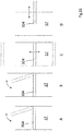
- Fig. 21 shows four schematic representations A to D respectively with a lane 17 of a storage system 10 analogous to the storage system.
- a storage system 10 analogous to the storage system.
- the alley 17 of the bearing system 10 only partially shown on a fixed handling bridge 304. This is therefore not along the longitudinal direction of the alley 17 movable. Nevertheless, in order optionally to allow the second conveyor 200, not shown, a free ride in the alley 17, ie along the longitudinal direction of the alley 17, or the first conveyor 100, optionally together with the cargo 16, a crossing of the alley 17, the stationary handling bridge 304 between the working position and the rest position. The handling bridge 304 can thus remain stationary in the alley 17, does not have to be parked at one end and can still be moved between the rest position and the working position.
- FIG. 21 is a side view of the storage system 10 with a viewing direction shown laterally in the alley 17.
- the handling bridge 304 can be pivoted about a horizontal and in the longitudinal direction of the alley 17, in particular substantially parallel to a lane wall, extending pivot axis.
- the working position is solid and the rest position shown in dashed lines.
- a representation B of Fig. 21 is a plan view of the storage system 10 as viewed from above into the alley 17 is shown.
- the handling bridge 304 can be pivoted about a vertical and in the lane 17 from bottom to top, in particular substantially parallel to a lane wall, extending pivot axis.
- the working position is solid and the rest position shown in dashed lines.
- the handling bridge 304 can be divided and to pivot the two parts independently of each other out of the alley. It is also possible to pivot the bridge or parts of the bridge about an axis out of the alley, wherein the pivot axis can also be arranged at a corner of the handling bridge. In principle, therefore, the handling bridge 304 can be handled like a swing bridge.
- a representation C of Fig. 21 is a side view of the storage system 10 with a viewing direction shown laterally in the alley 17.
- the handling bridge 304 can be displaced vertically in the lane 17, in particular substantially parallel to a lane wall.
- the handling bridge 304 can thus be moved either in the direction of a bottom of the alley 17 or in the direction of a bottom opposite the upper end. It is also possible to provide both ways of moving, wherein the rest position is reached at the bottom or at the upper end to allow the second conveyor 200 free passage.
- the working position is solid and the possible rest positions are shown in dashed lines.
- a representation D of Fig. 21 is a side view of the storage system 10 with a viewing direction shown laterally in the alley 17.
- the handling bridge 304 can be displaced or displaced horizontally in the alley 17, in particular substantially perpendicular to a lane wall. If the handling bridge 304 is completely pushed into the alley 17, this has reached the working position and can be overrun by the first conveyor 100 to cross the alley 17. If the handling bridge 304 is displaced in the direction of a non-illustrated storage space 19 of the alley 17, this has reached its rest position and are the lane 17 for a passage of the second funding free.
- the illustration D shows an intermediate position between the working position and the rest position.
- Fig. 21 described ways to switch between the rest position and the working position, even with a non-stationary handling bridge 304 or third conveyor 300 may be provided.
Applications Claiming Priority (1)
| Application Number | Priority Date | Filing Date | Title |
|---|---|---|---|
| DE102016108992.3A DE102016108992A1 (de) | 2016-05-14 | 2016-05-14 | Verfahren und Vorrichtung zum Lagern von Stückgut mit überbrückbaren Regalreihen |
Publications (1)
| Publication Number | Publication Date |
|---|---|
| EP3243769A1 true EP3243769A1 (fr) | 2017-11-15 |
Family
ID=58709863
Family Applications (1)
| Application Number | Title | Priority Date | Filing Date |
|---|---|---|---|
| EP17171189.8A Pending EP3243769A1 (fr) | 2016-05-14 | 2017-05-15 | Procédé et dispositif de stockage de marchandises au détail à l'aide de rangées d'étagères pouvant être reliées |
Country Status (2)
| Country | Link |
|---|---|
| EP (1) | EP3243769A1 (fr) |
| DE (1) | DE102016108992A1 (fr) |
Cited By (10)
| Publication number | Priority date | Publication date | Assignee | Title |
|---|---|---|---|---|
| CN108792400A (zh) * | 2018-07-06 | 2018-11-13 | 晋江凯燕新材料科技有限公司 | 具自动存取功能的智能仓库 |
| CN108945812A (zh) * | 2018-08-17 | 2018-12-07 | 苏州精濑光电有限公司 | 一种电子器件中转和储存设备 |
| EP3473562A1 (fr) * | 2017-10-23 | 2019-04-24 | Jörg Föller | Procédé et technologie de stockage des étagères hautes permettant de stocker la marchandise au moyen du stockage transversal orthogonal |
| CN110482100A (zh) * | 2019-08-12 | 2019-11-22 | 浙江睿索电子科技有限公司 | 一种智能仓储管理货架及控制方法 |
| CN110562652A (zh) * | 2019-07-30 | 2019-12-13 | 国网浙江省电力有限公司嘉兴供电公司 | 一种基于物联网的电力备件智能仓库 |
| CN111483804A (zh) * | 2020-04-24 | 2020-08-04 | 常州市新创智能科技有限公司 | 一种模具自动选取移动装置 |
| CN113335820A (zh) * | 2021-06-30 | 2021-09-03 | 广州普华灵动机器人技术有限公司 | 一种立体仓库与agv直接对接的入库及出库方法 |
| CN114988005A (zh) * | 2022-06-29 | 2022-09-02 | 山东西部智能科技有限公司 | 一种盒装物品管理系统 |
| CN115783580A (zh) * | 2022-10-24 | 2023-03-14 | 湖北凯乐仕通达科技有限公司 | 自动化存取系统及方法、自动化立体仓库 |
| WO2023116446A1 (fr) * | 2021-12-20 | 2023-06-29 | 北京极智嘉科技股份有限公司 | Système d'entrepôt tridimensionnel, et système d'étagères et dispositif de manipulation automatique associé |
Families Citing this family (1)
| Publication number | Priority date | Publication date | Assignee | Title |
|---|---|---|---|---|
| WO2018177875A1 (fr) | 2017-03-29 | 2018-10-04 | Dematic Gmbh | Procédé pour empiler automatiquement plusieurs couches de paquets sur un support |
Citations (8)
| Publication number | Priority date | Publication date | Assignee | Title |
|---|---|---|---|---|
| GB2094770A (en) * | 1981-03-13 | 1982-09-22 | Finsider Costr Metall Cmf | A conveyor device for a storage plant |
| EP1028074A1 (fr) * | 1999-02-10 | 2000-08-16 | Lagertechnik Gesellschaft m.b.H. | Magasin de stockage |
| DE202004012021U1 (de) | 2004-07-27 | 2005-12-15 | Bellheimer Metallwerk Gmbh | Lagersystem |
| DE102006008932A1 (de) | 2006-02-22 | 2007-08-23 | Bellheimer Metallwerk Gmbh | Lagerliftanordnung |
| DE102011115076A1 (de) | 2011-09-28 | 2013-03-28 | FAB GmbH Fördertechnik und Anlagenbau | Bewegungsvorrichtung für Transporteinheiten |
| DE102013005614A1 (de) * | 2013-04-04 | 2014-10-09 | Atlantic C Handels- Und Beratungs-Gmbh | Lager |
| DE102014012254A1 (de) | 2014-08-19 | 2016-02-25 | Lisa-Marie Amminger | Lager- und/oder Kommissioniersysteme |
| US20160060037A1 (en) * | 2014-09-03 | 2016-03-03 | Sergey N. Razumov | Storage system using lifting mechanism for collecting containers in desired sequence |
Family Cites Families (3)
| Publication number | Priority date | Publication date | Assignee | Title |
|---|---|---|---|---|
| DE102007016453B4 (de) * | 2007-03-30 | 2009-01-08 | SSI Schäfer Noell GmbH Lager- und Systemtechnik | Automatisiertes Kommissioniersystem mit integrierter Sortierfunktion und Verfahren zum Betreiben desselben |
| NL1033799C2 (nl) * | 2007-05-03 | 2008-11-10 | Scarabee Id B V | Systeem en werkwijze voor het opslaan van goederen. |
| EP2949605B1 (fr) * | 2014-05-28 | 2017-07-05 | Dematic GmbH | Procédé de renouvellement de commande en rendant disponible des unités de stockage à partir d'une installation de stockage dans une station de prélèvement |
-
2016
- 2016-05-14 DE DE102016108992.3A patent/DE102016108992A1/de active Pending
-
2017
- 2017-05-15 EP EP17171189.8A patent/EP3243769A1/fr active Pending
Patent Citations (8)
| Publication number | Priority date | Publication date | Assignee | Title |
|---|---|---|---|---|
| GB2094770A (en) * | 1981-03-13 | 1982-09-22 | Finsider Costr Metall Cmf | A conveyor device for a storage plant |
| EP1028074A1 (fr) * | 1999-02-10 | 2000-08-16 | Lagertechnik Gesellschaft m.b.H. | Magasin de stockage |
| DE202004012021U1 (de) | 2004-07-27 | 2005-12-15 | Bellheimer Metallwerk Gmbh | Lagersystem |
| DE102006008932A1 (de) | 2006-02-22 | 2007-08-23 | Bellheimer Metallwerk Gmbh | Lagerliftanordnung |
| DE102011115076A1 (de) | 2011-09-28 | 2013-03-28 | FAB GmbH Fördertechnik und Anlagenbau | Bewegungsvorrichtung für Transporteinheiten |
| DE102013005614A1 (de) * | 2013-04-04 | 2014-10-09 | Atlantic C Handels- Und Beratungs-Gmbh | Lager |
| DE102014012254A1 (de) | 2014-08-19 | 2016-02-25 | Lisa-Marie Amminger | Lager- und/oder Kommissioniersysteme |
| US20160060037A1 (en) * | 2014-09-03 | 2016-03-03 | Sergey N. Razumov | Storage system using lifting mechanism for collecting containers in desired sequence |
Cited By (17)
| Publication number | Priority date | Publication date | Assignee | Title |
|---|---|---|---|---|
| EP3473562A1 (fr) * | 2017-10-23 | 2019-04-24 | Jörg Föller | Procédé et technologie de stockage des étagères hautes permettant de stocker la marchandise au moyen du stockage transversal orthogonal |
| CN108792400B (zh) * | 2018-07-06 | 2023-12-01 | 晋江凯燕新材料科技有限公司 | 具自动存取功能的智能仓库 |
| CN108792400A (zh) * | 2018-07-06 | 2018-11-13 | 晋江凯燕新材料科技有限公司 | 具自动存取功能的智能仓库 |
| CN108945812A (zh) * | 2018-08-17 | 2018-12-07 | 苏州精濑光电有限公司 | 一种电子器件中转和储存设备 |
| CN108945812B (zh) * | 2018-08-17 | 2024-04-16 | 苏州精濑光电有限公司 | 一种电子器件中转和储存设备 |
| CN110562652A (zh) * | 2019-07-30 | 2019-12-13 | 国网浙江省电力有限公司嘉兴供电公司 | 一种基于物联网的电力备件智能仓库 |
| CN110562652B (zh) * | 2019-07-30 | 2021-01-26 | 国网浙江省电力有限公司嘉兴供电公司 | 一种基于物联网的电力备件智能仓库 |
| CN110482100A (zh) * | 2019-08-12 | 2019-11-22 | 浙江睿索电子科技有限公司 | 一种智能仓储管理货架及控制方法 |
| CN110482100B (zh) * | 2019-08-12 | 2020-12-11 | 浙江睿索电子科技有限公司 | 一种智能仓储管理货架及控制方法 |
| CN111483804B (zh) * | 2020-04-24 | 2021-08-10 | 常州市新创智能科技有限公司 | 一种模具自动选取移动装置 |
| CN111483804A (zh) * | 2020-04-24 | 2020-08-04 | 常州市新创智能科技有限公司 | 一种模具自动选取移动装置 |
| CN113335820A (zh) * | 2021-06-30 | 2021-09-03 | 广州普华灵动机器人技术有限公司 | 一种立体仓库与agv直接对接的入库及出库方法 |
| WO2023116446A1 (fr) * | 2021-12-20 | 2023-06-29 | 北京极智嘉科技股份有限公司 | Système d'entrepôt tridimensionnel, et système d'étagères et dispositif de manipulation automatique associé |
| CN114988005A (zh) * | 2022-06-29 | 2022-09-02 | 山东西部智能科技有限公司 | 一种盒装物品管理系统 |
| CN114988005B (zh) * | 2022-06-29 | 2024-01-05 | 山东西部智能科技有限公司 | 一种盒装物品管理系统 |
| CN115783580A (zh) * | 2022-10-24 | 2023-03-14 | 湖北凯乐仕通达科技有限公司 | 自动化存取系统及方法、自动化立体仓库 |
| CN115783580B (zh) * | 2022-10-24 | 2023-06-30 | 湖北凯乐仕通达科技有限公司 | 自动化存取系统及方法、自动化立体仓库 |
Also Published As
| Publication number | Publication date |
|---|---|
| DE102016108992A1 (de) | 2017-11-16 |
Similar Documents
| Publication | Publication Date | Title |
|---|---|---|
| EP3243769A1 (fr) | Procédé et dispositif de stockage de marchandises au détail à l'aide de rangées d'étagères pouvant être reliées | |
| EP2607292B1 (fr) | Système de transport des marchandises disposées sur les aides auxiliaires | |
| EP2794432B1 (fr) | Système de stockage sur rayonnages et son procédé de fonctionnement | |
| EP2709933B1 (fr) | Système d'entrepôt à rayonnages | |
| DE102011014394C5 (de) | Zirkulares Roaming für ein Lager- und Kommissioniersystem | |
| EP2673217B1 (fr) | Système de stockage sur rayonnages et son procédé de fonctionnement | |
| EP2287093B1 (fr) | Système de rayonnage et procédé de fonctionnement d'un système de rayonnage | |
| EP3283418B1 (fr) | Procédé et installation de transbordement de conteneurs servant mettre en stock et à retirer du stock des conteneurs dans des entrepôts de conteneurs | |
| EP0776291B1 (fr) | Procede et dispositif de transbordement de charge | |
| EP1638866A1 (fr) | Procede et dispositif pour manipuler des auxiliaires de chargement | |
| DE102013100048A1 (de) | Kommissioniereinrichtung | |
| DE102014003451A1 (de) | Reagalbediengerät mit hochgesetzter Fahrschiene | |
| DE102013014102A1 (de) | Verfahren und Anlagen zum Fördern von Ladungsträgern | |
| DE2113202B2 (de) | Warenlager | |
| WO2013044895A1 (fr) | Dispositif de déplacement d'unités de transport | |
| EP1422169B1 (fr) | Magasin avec chariots sur rails pour le stockage et déstockage d'articles | |
| EP1028074B1 (fr) | Magasin de stockage | |
| EP3473562B1 (fr) | Procédé et technologie de stockage des étagères hautes permettant de stocker la marchandise au moyen du stockage transversal orthogonal | |
| EP0096784A1 (fr) | Dépôt à rayonnages entièrement automatique | |
| DE202018006447U1 (de) | Flächenspeicher | |
| AT500227B1 (de) | Transportwagen zum ein- und auslagern von transportgut | |
| DE20023638U1 (de) | Hochredundantes Lagersystem in Regalbauweise u.a. Systematik der Lagerfüllgradoptimierung dieses und ähnlicher Lagersysteme |
Legal Events
| Date | Code | Title | Description |
|---|---|---|---|
| PUAI | Public reference made under article 153(3) epc to a published international application that has entered the european phase |
Free format text: ORIGINAL CODE: 0009012 |
|
| STAA | Information on the status of an ep patent application or granted ep patent |
Free format text: STATUS: THE APPLICATION HAS BEEN PUBLISHED |
|
| AK | Designated contracting states |
Kind code of ref document: A1 Designated state(s): AL AT BE BG CH CY CZ DE DK EE ES FI FR GB GR HR HU IE IS IT LI LT LU LV MC MK MT NL NO PL PT RO RS SE SI SK SM TR |
|
| AX | Request for extension of the european patent |
Extension state: BA ME |
|
| STAA | Information on the status of an ep patent application or granted ep patent |
Free format text: STATUS: REQUEST FOR EXAMINATION WAS MADE |
|
| 17P | Request for examination filed |
Effective date: 20180515 |
|
| RBV | Designated contracting states (corrected) |
Designated state(s): AL AT BE BG CH CY CZ DE DK EE ES FI FR GB GR HR HU IE IS IT LI LT LU LV MC MK MT NL NO PL PT RO RS SE SI SK SM TR |
|
| STAA | Information on the status of an ep patent application or granted ep patent |
Free format text: STATUS: EXAMINATION IS IN PROGRESS |
|
| 17Q | First examination report despatched |
Effective date: 20181019 |
|
| STAA | Information on the status of an ep patent application or granted ep patent |
Free format text: STATUS: EXAMINATION IS IN PROGRESS |
|
| STAA | Information on the status of an ep patent application or granted ep patent |
Free format text: STATUS: EXAMINATION IS IN PROGRESS |
|
| GRAP | Despatch of communication of intention to grant a patent |
Free format text: ORIGINAL CODE: EPIDOSNIGR1 |
|
| STAA | Information on the status of an ep patent application or granted ep patent |
Free format text: STATUS: GRANT OF PATENT IS INTENDED |