EP3242069B1 - Kartuschenvorrichtung zur schmierung einer maschine - Google Patents
Kartuschenvorrichtung zur schmierung einer maschine Download PDFInfo
- Publication number
- EP3242069B1 EP3242069B1 EP16168435.2A EP16168435A EP3242069B1 EP 3242069 B1 EP3242069 B1 EP 3242069B1 EP 16168435 A EP16168435 A EP 16168435A EP 3242069 B1 EP3242069 B1 EP 3242069B1
- Authority
- EP
- European Patent Office
- Prior art keywords
- closure element
- cartridge
- machine
- end portion
- pneumatic system
- Prior art date
- Legal status (The legal status is an assumption and is not a legal conclusion. Google has not performed a legal analysis and makes no representation as to the accuracy of the status listed.)
- Active
Links
- 230000001050 lubricating effect Effects 0.000 title claims description 23
- 239000000314 lubricant Substances 0.000 claims description 21
- 230000008878 coupling Effects 0.000 claims description 19
- 238000010168 coupling process Methods 0.000 claims description 19
- 238000005859 coupling reaction Methods 0.000 claims description 19
- 230000000903 blocking effect Effects 0.000 claims description 15
- 238000000034 method Methods 0.000 claims description 4
- 238000003780 insertion Methods 0.000 claims description 3
- 230000037431 insertion Effects 0.000 claims description 3
- 239000005022 packaging material Substances 0.000 description 6
- 239000000463 material Substances 0.000 description 5
- 238000007373 indentation Methods 0.000 description 4
- 229910052751 metal Inorganic materials 0.000 description 4
- 239000002184 metal Substances 0.000 description 4
- 150000001399 aluminium compounds Chemical class 0.000 description 3
- 239000011888 foil Substances 0.000 description 3
- 238000013022 venting Methods 0.000 description 3
- 230000003116 impacting effect Effects 0.000 description 2
- 239000004033 plastic Substances 0.000 description 2
- 229920003023 plastic Polymers 0.000 description 2
- 229920002635 polyurethane Polymers 0.000 description 2
- 239000004814 polyurethane Substances 0.000 description 2
- 208000019300 CLIPPERS Diseases 0.000 description 1
- 208000021930 chronic lymphocytic inflammation with pontine perivascular enhancement responsive to steroids Diseases 0.000 description 1
- 238000004891 communication Methods 0.000 description 1
- 238000010276 construction Methods 0.000 description 1
- 238000011161 development Methods 0.000 description 1
- 239000004519 grease Substances 0.000 description 1
- 238000009434 installation Methods 0.000 description 1
- 239000007788 liquid Substances 0.000 description 1
- 238000005461 lubrication Methods 0.000 description 1
- 238000012423 maintenance Methods 0.000 description 1
- 238000007789 sealing Methods 0.000 description 1
- 229910001220 stainless steel Inorganic materials 0.000 description 1
- 239000010935 stainless steel Substances 0.000 description 1
- 239000002699 waste material Substances 0.000 description 1
Images


Classifications
-
- F—MECHANICAL ENGINEERING; LIGHTING; HEATING; WEAPONS; BLASTING
- F16—ENGINEERING ELEMENTS AND UNITS; GENERAL MEASURES FOR PRODUCING AND MAINTAINING EFFECTIVE FUNCTIONING OF MACHINES OR INSTALLATIONS; THERMAL INSULATION IN GENERAL
- F16N—LUBRICATING
- F16N7/00—Arrangements for supplying oil or unspecified lubricant from a stationary reservoir or the equivalent in or on the machine or member to be lubricated
- F16N7/38—Arrangements for supplying oil or unspecified lubricant from a stationary reservoir or the equivalent in or on the machine or member to be lubricated with a separate pump; Central lubrication systems
-
- F—MECHANICAL ENGINEERING; LIGHTING; HEATING; WEAPONS; BLASTING
- F16—ENGINEERING ELEMENTS AND UNITS; GENERAL MEASURES FOR PRODUCING AND MAINTAINING EFFECTIVE FUNCTIONING OF MACHINES OR INSTALLATIONS; THERMAL INSULATION IN GENERAL
- F16N—LUBRICATING
- F16N11/00—Arrangements for supplying grease from a stationary reservoir or the equivalent in or on the machine or member to be lubricated; Grease cups
- F16N11/10—Arrangements for supplying grease from a stationary reservoir or the equivalent in or on the machine or member to be lubricated; Grease cups by pressure of another fluid
-
- B—PERFORMING OPERATIONS; TRANSPORTING
- B65—CONVEYING; PACKING; STORING; HANDLING THIN OR FILAMENTARY MATERIAL
- B65D—CONTAINERS FOR STORAGE OR TRANSPORT OF ARTICLES OR MATERIALS, e.g. BAGS, BARRELS, BOTTLES, BOXES, CANS, CARTONS, CRATES, DRUMS, JARS, TANKS, HOPPERS, FORWARDING CONTAINERS; ACCESSORIES, CLOSURES, OR FITTINGS THEREFOR; PACKAGING ELEMENTS; PACKAGES
- B65D83/00—Containers or packages with special means for dispensing contents
- B65D83/0005—Containers or packages provided with a piston or with a movable bottom or partition having approximately the same section as the container
-
- F—MECHANICAL ENGINEERING; LIGHTING; HEATING; WEAPONS; BLASTING
- F16—ENGINEERING ELEMENTS AND UNITS; GENERAL MEASURES FOR PRODUCING AND MAINTAINING EFFECTIVE FUNCTIONING OF MACHINES OR INSTALLATIONS; THERMAL INSULATION IN GENERAL
- F16N—LUBRICATING
- F16N19/00—Lubricant containers for use in lubricators or lubrication systems
-
- F—MECHANICAL ENGINEERING; LIGHTING; HEATING; WEAPONS; BLASTING
- F16—ENGINEERING ELEMENTS AND UNITS; GENERAL MEASURES FOR PRODUCING AND MAINTAINING EFFECTIVE FUNCTIONING OF MACHINES OR INSTALLATIONS; THERMAL INSULATION IN GENERAL
- F16N—LUBRICATING
- F16N37/00—Equipment for transferring lubricant from one container to another
-
- F—MECHANICAL ENGINEERING; LIGHTING; HEATING; WEAPONS; BLASTING
- F16—ENGINEERING ELEMENTS AND UNITS; GENERAL MEASURES FOR PRODUCING AND MAINTAINING EFFECTIVE FUNCTIONING OF MACHINES OR INSTALLATIONS; THERMAL INSULATION IN GENERAL
- F16N—LUBRICATING
- F16N7/00—Arrangements for supplying oil or unspecified lubricant from a stationary reservoir or the equivalent in or on the machine or member to be lubricated
- F16N7/14—Arrangements for supplying oil or unspecified lubricant from a stationary reservoir or the equivalent in or on the machine or member to be lubricated the lubricant being conveyed from the reservoir by mechanical means
-
- F—MECHANICAL ENGINEERING; LIGHTING; HEATING; WEAPONS; BLASTING
- F16—ENGINEERING ELEMENTS AND UNITS; GENERAL MEASURES FOR PRODUCING AND MAINTAINING EFFECTIVE FUNCTIONING OF MACHINES OR INSTALLATIONS; THERMAL INSULATION IN GENERAL
- F16N—LUBRICATING
- F16N37/00—Equipment for transferring lubricant from one container to another
- F16N2037/006—Filling
Definitions
- the present invention relates to a cartridge device and a method for lubricating a machine, preferably a clipping machine, having a pneumatic system and a pump unit driven by the pneumatic system.
- the present invention further relates to a lubricating device comprising the cartridge device, and to a machine comprising the lubricating device. Further, the present invention relates to a use of the cartridge device with such a machine and to a use of a collapsible reservoir with the cartridge device.
- the invention relates to a cartridge device for lubricating a machine, preferably a clipping machine, having a pneumatic system and a pump unit driven by the pneumatic system, the cartridge device comprising a cartridge container for accommodating a supply of lubricant having a longitudinal axis defining a longitudinal direction, wherein the cartridge container comprises a first end portion and a second end portion located opposite the first end portion in the longitudinal direction, and the cartridge device comprising a first closure element for detachably coupling the first end portion of the cartridge container to a suction side of the pump unit, wherein the first closure element has a delivery opening for supplying lubricant contained within the cartridge container to the suction side of the pump unit.
- the cartridge container is closed off relative to the surrounding by means of a first closure element and a piston sealingly movable within the cartridge container.
- the cartridge container is made of a substantially rigid, non-collapsible plastics material.
- the first closure element is provided with a threaded collar to allow for a threaded attachment between the cartridge device and the pump unit. Upon use of the cartridge device, the tip of the threaded collar is to be cut off to provide a delivery opening for the lubricant. Once the supply of lubricant accommodated within the cartridge container is used up, the cartridge device is disposed of.
- CN utility model 2 508 089 discloses a grease releasing device having a cylindrical storage tank made of a metal shell which houses a polyurethane inner bag.
- the cylindrical storage tank comprises a lid having an opening at a first end thereof.
- a valve is arranged at a second end of the cylindrical storage tank allowing injecting a liquid gas inside the metal shell for compressing the polyurethane inner bag towards the first end of the cylindrical storage tank.
- a cartridge device as defined in claim 1, wherein, inter alia, the first closure element is detachably coupled or coupleable to the first end portion of the cartridge container and wherein the first end portion of the cartridge container is configured so as to allow for a collapsible reservoir containing the supply of lubricant to be inserted into and removed from the cartridge container.
- the first closure element comprises at least one bar bridging over the delivery opening of the first closure element for detaining the collapsible reservoir within the cartridge container.
- the supply of lubricant may be contained within a collapsible reservoir which is to be inserted into the cartridge container. Once the supply of lubricant within the collapsible reservoir is used up, the collapsible reservoir is disposed of and the cartridge container may be reused by inserting a new collapsible reservoir into the same. The waste is thus limited to the collapsible reservoir compared to the cartridge container as it is known in the art.
- the collapsible reservoir requires less material and is simpler to produce than the sturdy cartridge containers known in the art.
- the collapsible reservoir may be made of a thin packaging material such as an aluminium compound foil.
- the collapsible reservoir is closed by clips made of metal or any other suitable material at either end.
- the cartridge container may be made of a material other than plastics, for instance metal such as stainless steel, which resists high temperatures and may thus be easily cleansed or sterilized. This may be of special importance in food applications.
- the cartridge device is integrated into the machine to be lubricated and disassembled quickly to allow for a quick and easy refilling of the cartridge device with a collapsible reservoir.
- the delivery opening may be formed within the first closure element such that the first closure element can be readily coupled to the suction side of the pump unit without having to cut off part of the first closure element or otherwise create a delivery opening within the first closure element for the supply of lubricant to the pump unit.
- the first end portion is the end portion of the cartridge container which is coupled to the suction side of the pump unit, wherein the second end portion is the end portion of the cartridge container which is located remote from the suction side of the pump unit.
- At least one bar bridging over the delivery opening for detaining the collapsible reservoir within the cartridge container is provided.
- the bar holds back packaging material of the collapsible reservoir which may otherwise be sucked towards the suction side of the pump unit.
- the cartridge device may further comprise a piston moveable in the longitudinal direction within the cartridge container, the piston fitting substantially airtight against an inner wall of the cartridge container.
- the piston is advanced by the prevailing atmospheric pressure of the surrounding of the cartridge device during an operation of the pump unit because of a negative pressure developing within the cartridge container due to the sucking action of the pump unit.
- the piston applies additional pressure to the end of the collapsible reservoir remote from the suction side of the pump unit.
- This may prevent the collapsible reservoir from contracting or creasing due to the suction of the pump unit in a disadvantageous manner.
- the collapsible reservoir may crease in such a way that an amount of lubricant cannot be sucked out of the collapsible reservoir by the pump unit.
- Supporting the sucking action of the pump unit by providing an additional pressure by means of the piston at the end of the collapsible reservoir remote from the suction side of the pump unit may reduce or even eliminate this undesirable creasing behavior of the collapsible reservoir.
- the first closure element may be detached from the cartridge container. Since the piston is located at the first end portion of the cartridge device upon refilling, either the collapsible reservoir may be inserted via the first end portion to push the piston back towards the second end portion or the orientation of the cartridge container may be reversed such that the first end portion becomes the second end portion of the cartridge device and vice versa.
- the first closure element and the first end portion may be provided with a bayonet lock.
- the cartridge device may further comprise a second closure element provided at the second end portion of the cartridge container, wherein preferably the second closure element can comprise an air duct for providing a flow path into and out of the cartridge device.
- the cartridge container is closed off at both ends thereof against the surroundings of the cartridge device.
- the air duct provides for a communication between the cartridge container and its surroundings such that no negative pressure caused by the suction action of the pump unit establishes within the cartridge container.
- the air duct may simply be an opening within the second closure element or may be of a more elaborate construction.
- the second closure element may be formed separately from the second end portion of the cartridge container.
- the second closure element may be detachably or fixedly connected to the second end portion.
- the second closure element may be formed integrally with the second end portion and may thus form part of the cartridge container. In this case, in order to refill the cartridge device it is not possible to simply reverse the orientation of the cartridge container. Instead, the cartridge container is to be filled via the first end portion thereof.
- the air duct ensures that air within the cartridge container which is replaced by the collapsible reservoir when filling the cartridge device therewith is vented out through the air duct of the second closure element.
- the pump unit may be sensitive to an amount of air being sucked into the suction side thereof. It is thus preferable that the air duct of the second closure element is coupled or coupleable to the pneumatic system for providing a positive pressure between the piston and the second closure element, thereby moving the piston towards the first end portion.
- the pneumatic system of the machine may provide a pressure between 5 and 7 bar such that the positive pressure applied to the back of the piston, i. e. between the piston and the second closure element, may be between 0.5 bar and 3 bar. It has been found that a positive pressure of 2 bar allows for an operation of the pump unit and the cartridge device requiring low to no maintenance.
- both the first closure element and the second closure element may be detachably connected to the cartridge container such that the first and second closure elements may be detached from the cartridge container to bring the piston back to the second end portion as described above.
- the first closure element and the first end portion as well as the second closure element and the second end portion may be provided with a bayonet lock.
- the second closure element may comprise a safety valve having an open position and a closed position, the safety valve being biased towards the closed position and configured to move into the open position upon insertion of the collapsible reservoir into the cartridge container.
- the safety valve may ensure that during an insertion of a collapsible reservoir into the cartridge container via the first end portion no pressure builds up in an air supply line connecting the cartridge device to the pneumatic system.
- the air within the cartridge container that is being compressed by the movement of the piston towards the second end portion of the cartridge container upon refilling may be vented into the surrounding of the cartridge device via the safety valve.
- the safety valve may also have a blocking position different from the closed position and be configured to move into the blocking position upon pneumatically coupling the air duct of the second closure element to the pneumatic system of the machine.
- the safety valve may control both the supply of air into and the venting of air out of the cartridge device.
- the safety valve may be configured to open at a predetermined first pressure threshold but to close once the pressure exceeds a predetermined second pressure threshold which is greater than the first pressure threshold.
- the safety valve may be provided in the flow path for supplying air into and venting air out of the cartridge device. There is no need to separate the flow path for supplying air into the cartridge device from the flow path for venting air out of the same.
- the first closure element may comprise at least one protrusion protruding from the first closure element towards the second end portion for piercing the collapsible reservoir so as to release lubricant therefrom.
- the collapsible reservoir is instead opened upon coupling the first closure element to the first end portion of the cartridge container. This facilitates the handling and refilling of the cartridge container.
- the material when piercing a collapsible reservoir made of a thin packaging material, such as an aluminium compound foil, by means of protrusions provided at the first closure element, the material may rupture further due to the sucking action of the pump unit, thus releasing more lubricant.
- a thin packaging material such as an aluminium compound foil
- a lubricating device for lubricating a machine having a pneumatic system comprises a cartridge device of the invention and a pump unit driven by the pneumatic system.
- a machine having a pneumatic system comprises a lubricating device of the invention.
- the machine comprises a quick coupling for detachably coupling the cartridge device of the lubricating device to the pneumatic system. This facilitates removing the cartridge device from the pump unit and thus the handling and possibly the refilling of the cartridge device.
- a method for lubricating a machine having a pneumatic system and a pump unit driven by the pneumatic system using a cartridge device of the invention comprises the steps of inserting a collapsible reservoir into the cartridge container via the first end portion of the cartridge container, coupling the first closure element to the suction side of the pump unit, and coupling the first end portion of the cartridge container to the first closure element.
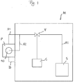
- Fig. 1 schematically illustrates a machine M comprising a pneumatic system S connected via an air supply line A1 to a pump unit P to drive the same.
- Air supply line A1 may be pneumatically connected and disconnected from pneumatic system S by means of a valve V. Valve V may be controlled by a control unit C of machine M.
- pump unit P When air supply line A1 is pneumatically connected to pump unit P by opening valve V, pump unit P is operated by the pressure provided by pneumatic system S.
- air supply line A1 is disconnected from pump unit P by closing valve V, the supply of pressure from pneumatic system S and thus the operation of pump unit P stops.
- Pump unit P is connected to a cartridge device 10 as will be described in more detail below.
- Cartridge device 10 may be part of machine M or may be provided separately from machine M.
- Cartridge device 10 is provided with a supply of lubricant for lubricating machine M. By the operation of pump unit P, lubricant is delivered from cartridge device 10 via a lubricant line
- An air supply line A2 preferably branches off from air supply line A1 downstream of valve V to provide a pressure to cartridge device 10 for assisting the release of lubricant from cartridge device 10.
- air supply line A2 may emanate directly from pneumatic system S such that air supply lines A1, A2 may be provided independently from each other.
- Machine M may be a clipping machine comprising its own pneumatic system S, such as an automatic double-clipper, an automatic sealing/clipping machine, or an automatic hanging line which may be used in an automation line with defined clipping machines.
- Pneumatic system S of machine M is used for driving certain components of machine M. For instance, when machine M is a clipping machine, pneumatic system S may be used for driving the gathering or displacer plates of the clipping machine.
- Pump unit P may be a known lubricating pump unit driven by the pneumatic system S of the machine M it is mounted on.
- pump unit P may be operated by the pneumatic system S of machine M in a lubricating phase in which the actual or intended operation of machine M is deactivated.
- the lubricating phase may be followed up by the actual or intended operation of machine M in which pump unit P is deactivated and air supply lines A1, A2 are disconnected from pneumatic system S by closing valve V.
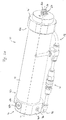
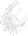
- Figs. 2a and 2b show a cartridge device 10 with a cartridge container 12.
- cartridge container 12 is formed as a cylindrical tube extending along a longitudinal axis L.
- Cylindrical tube 12 has a first end portion 12a and an opposing second end portion 12b.
- a first closure element 14 is detachably coupled to first end portion 12a
- a second closure element 16 is detachably coupled to second end portion 12b.
- Air supply line A2 branching off from air supply line A1 connects second closure element 16 to pneumatic system S as will be described in more detail below.
- Air supply line section A2 is provided with a quick coupling 18 for readily physically connecting and disconnecting air supply line A2 from pneumatic system S.
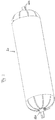
- a collapsible reservoir 20 as shown in Fig. 3 may exchangeably be inserted into cylindrical tube 12.
- Collapsible reservoir 20 may be formed of a thin packaging material, such as an aluminium compound foil, and closed by means of clips 22a, 22b.
- Collapsible reservoir 20 may be filled with a lubricant commonly used for lubricating machines, in particular for bearings of machines.
- first closure element 14 is provided with a delivery duct 26 extending through a threaded collar 27 for detachably coupling first closure element 14 to pump unit P.
- Delivery duct 26 extends substantially parallel to longitudinal axis L. Delivery duct 26 allows an inner space 12c of cylindrical tube 12 to communicate with the surrounding of cartridge device 10, in particular the suction side of pump unit P.
- Delivery duct 26 has a first duct end 26a which, in an assembled state of delivery device 10, is positioned in proximity to the suction side of pump unit P, and a second duct end 26b remote from first duct end 26a.
- First duct end 26a of delivery duct 26 forms the delivery opening of cartridge device 10.
- cylindrical tube 12 is provided at its outer wall 12d with a thread 12e
- first closure element 14 is provided at its inner circumferential wall 14a with a thread 14b.
- First end portion 12a is in threaded engagement with first closure element 14 by means of threads 12e, 14b so as to provide a detachable coupling between cylindrical tube 12 and first closure element 14.
- first closure element 14 may be detachably coupled to first end portion 12a by means of a bayonet lock.
- An O-ring 28 is provided at first end portion 12a within an annular groove 12f formed within outer wall 12d so as to provide an airtight seal between cylindrical tube 12 and first closure element 14.
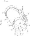
- Protrusions 30a, 30b are each provided within an indentation 14c, 14d of first closure element 14 indented towards delivery opening 26a relative to a side 14e of first closure element 14 facing second end portion 12b.
- Protrusions 30a, 30b are fixed by means of nuts 32a, 32b within indentations 14c, 14d such that pointed free ends 34a, 34b of protrusions 30a, 30b are directed towards the second end portion 12b.
- protrusions 30a, 30b may pierce collapsible reservoir 20 disposed within cylindrical tube 12 when coupling first closure element 14 to first end portion 12a.
- threads 12e, 14b are configured such that cylindrical tube 12 may be mounted to first closure element 14 by a quarter turn of first end portion 12a relative to first closure element 14.
- a quarter turn a half turn or any number of turns, odd or even, may also be feasible.
- protrusions 30a, 30b may be provided which may differ in shape and installation from protrusions 30a, 30b described in this example.
- protrusions 30a, 30b may be provided integral with first closure element 14.
- protrusions 30a, 30b may be provided as blades for opening collapsible reservoir 20 predominantly by cutting rather than by piercing.
- Delivery duct 26 is partially covered by a bar 14f formed between indentations 14c, 14d at side 14e of first closure element 14.
- Bar 14f is provided approximately across the centre of delivery duct 26 to prevent delivery duct 26 from becoming blocked or clogged up by one of clips 22a, 22b and/or by packaging material of collapsible reservoir 20. Instead, bar 14f holds back collapsible reservoir 20 in a manner that allows inner space 12c to communicate with delivery opening 26a when collapsible reservoir 20 is inserted into cylindrical tube 12.
- a piston 36 is sealingly and slidably inserted within inner space 12c of cylindrical tube 12.
- Piston 36 forms an airtight seal with an inner wall 12g of cylindrical tube 12 by means of two O-rings 38a, 38b.
- Second closure element 16 comprises an end plate 16a and an attachment member 16b mounted on end plate 16a by means of screws 40a, 40b (see Fig. 2b ).
- End plate 16a is axially confined in a direction towards first end portion 12a by means of an annular shoulder 12h provided in inner wall 12g and in a direction towards second end portion 12b by means of a retaining ring 42 inserted within an annular groove 12i provided in inner wall 12g.
- a stepped pin 44 is disposed within a stepped opening 46 of attachment member 16b and confined therein by means of fixing members 48a, 48b.
- Fixing member 48b is coupled to opening 46 my means of a threaded engagement (not shown).
- Stepped pin 44 extends perpendicular to longitudinal axis L and is supported within opening 46 by means of an annular shoulder 46a provided within opening 46 which engages an annular step shoulder 44a of pin 44.
- a ring space 50 is formed between pin 44 and opening 46 about midway of pin 44 and is sealed by means of two O-rings 52a, 52b. Between a bottom end 44b of pin 44 and a bottom end 46b of opening 46, a circular space 54 is formed. Ring space 50 and circular space 54 provide part of a flow path present within second closure element 16 which is described in detail below.
- Pin 44 is provided with a blind hole 56 extending from bottom end 44b of pin 44 to about midway of pin 44.
- Blind hole 56 communicates with four passage openings 58a, 58b, 58c, 58d extending from blind hole 56 radially outwardly through pin 44 which in turn communicate with ring space 50.
- Ring space 50 communicates with a passage opening 60 (see Fig. 6 ) extending within attachment member 16b which in turn communicates with a passage opening 62 provided in end plate 16a (see Fig. 5 ).
- Passage opening 62 communicates with a cylindrical space 64 provided between piston 36 and end plate 16a.
- An O-ring 66 provides an airtight seal between attachment member 16b and end plate 16a.
- Air duct 68 receives a positive pressure from pneumatic system S of machine M via air supply line A2.
- the connection 70 between air supply line A2 and attachment member 16b is shown in Fig. 2 .
- the positive pressure of air duct 68 is supplied to cylindrical tube 12 via passage opening 62 in end plate 16a such that the positive pressure may act upon a side 36a of piston 36 facing second closure element 16.
- an opening 72 is provided for accommodating a safety valve 74.
- Safety valve 74 is confined within opening 72 by means of a fixing member 76 having a through-hole 78.
- Safety valve 74 extends perpendicular to pin 44.
- Safety valve 74 comprises a valve body 80 and an elastic return member 82 in the form of a resilient spring supported by fixing member 76.
- a ring space 84 is formed between opening 72 and valve body 80.
- Spring 82 is biased towards the closed position in which valve body 80 is pressed against a first valve seat 72a.
- First valve seat 72a is provided by an annular step shoulder of opening 72.
- an O-ring 86 provides a seal between valve body 80 and first valve seat 72a and reduces sound caused by valve body 80 impacting on first valve seat 72a.
- Fixing member 76 provides a second valve seat 76a for valve body 80 remote from first valve seat 72a.
- safety valve 74 When valve body 80 is pressed against second valve seat 76a, safety valve 74 is in its blocking position. In the blocking position of safety valve 74, an O-ring 88 provides a seal between valve body 80 and second valve seat 76a and reduces sound caused by valve body 80 impacting on second valve seat 76a.
- safety valve 74 When safety valve 74 is in the closed position or in the blocking position, through-hole 78 is blocked off from air duct 68 by means of valve body 80 being pressed against first valve seat 72a or second valve seat 76a, respectively.
- air duct 68 communicates via ring space 84 and through-hole 78 with the surrounding of cartridge device 10.
- Valve body 80 moves from the closed position into the open position when the pressure within air duct 68 exceeds a predetermined first pressure threshold.
- valve body 80 is moved into the blocking position.
- cartridge device 10 With reference to Figs. 2 , 5 and 6 , the function of cartridge device 10 is explained.
- cylindrical tube 12 filled with collapsible reservoir 20 and connected with second closure element 16 is threadedly coupled to first closure element 14 by means of threads 12e, 14b, whereby collapsible reservoir 20 is slit open by protrusions 30a, 30b.
- First closure element 14 is already threadedly coupled to the suction side of pump unit P by means of threaded collar 27. Then, by opening valve V, air supply line A1 is pneumatically connected to pump unit P so as to drive the same, and air supply line A2 is pneumatically connected to cartridge device 10, i. e. attachment member 16b of second closure element 16, so as to supply pressure to air duct 68.
- air duct 68 Upon connecting air duct 68 to pneumatic system S of machine M, the pressure within air duct 68 exceeds the predetermined second threshold such that valve body 80 is pressed against second valve seat 76a, i. e. safety valve 74 is pressed into its blocking position. In the blocking position of safety valve 74, air duct 68 cannot communicate with through-hole 78 of safety valve 74. As a result, pressure builds up within cylindrical space 64 and piston 36 is pushed towards first end portion 12a of cylindrical tube 12. Thereby, collapsible reservoir 20 received within inner space 12c of cylindrical tube 12 is deformed and lubricant contained therein is released through delivery opening 26a formed within first closure element 14.
- a new reservoir 20 is inserted into cylindrical tube 12 via first end portion 12a.
- piston 36 is pushed towards second closure element 16.
- pressure builds up within cylindrical space 64 communicating with passage opening 62 of end plate 16a and ring space 50 of attachment member 16b.
- valve body 80 is moved from the closed position into the open position and vents air out of cartridge device 10.
- the predetermined first pressure threshold and the predetermined second pressure threshold may be adjusted such that safety valve 74 is not moved into the blocking position upon refilling cartridge device 10.
- the predetermined first pressure threshold may be equal to or greater than the atmospheric pressure prevailing within the surrounding of cartridge device 10.
Claims (14)
- Kartuschenvorrichtung (10) zum Schmieren einer Maschine (M), vorzugsweise einer Clipmaschine, wobei die Maschine (M) ein pneumatisches System (S) und eine von dem pneumatischen System (S) angetriebene Pumpeneinheit (P) aufweist, wobei die Kartuschenvorrichtung (10) umfasst:- einen Kartuschenbehälter (12) zum Aufnehmen eines faltbaren Reservoirs (20), das einen Schmiermittelvorrat enthält, wobei der Kartuschenbehälter (12) eine Längsachse (L) aufweist, die eine Längsrichtung definiert, wobei der Kartuschenbehälter (12) einen ersten Endabschnitt (12a) und einen zweiten Endabschnitt (12b) umfasst, der in der Längsrichtung gegenüber dem ersten Endabschnitt (12a) angeordnet ist, und- ein erstes Verschlusselement (14) zum lösbaren Koppeln des ersten Endabschnitts (12a) des Kartuschenbehälters (12) mit einer Saugseite der Pumpeneinheit (P), wobei das erste Verschlusselement (14) eine Abgabeöffnung (26a) zum Zuführen von in dem Kartuschenbehälter (12) enthaltenem Schmiermittel zu der Saugseite der Pumpeneinheit (P) aufweist,- wobei das erste Verschlusselement (14) lösbar mit dem ersten Endabschnitt (12a) des Kartuschenbehälters (12) koppelbar ist, wobei der erste Endabschnitt (12a) des Kartuschenbehälters (12) so konfiguriert ist, dass das faltbare Reservoir (20) in den Kartuschenbehälter (12) eingesetzt und aus diesem entfernt werden kann,dadurch gekennzeichnet, dass das erste Verschlusselement (14) mindestens einen Steg (14f) aufweist, der die Abgabeöffnung (26a) des ersten Verschlusselements (14) überbrückt, um das faltbare Reservoir (20) innerhalb des Kartuschenbehälters (12) festzuhalten.
- Kartuschenvorrichtung (10) nach Anspruch 1,
ferner umfassend einen in Längsrichtung innerhalb des Kartuschenbehälters (12) bewegbaren Kolben (36), wobei der Kolben (36) im Wesentlichen luftdicht an einer Innenwand (12e) des Kartuschenbehälters (12) anliegt. - Kartuschenvorrichtung (10) nach Anspruch 1 oder 2,
ferner umfassend ein zweites Verschlusselement (16), das an dem zweiten Endabschnitt (12b) des Kartuschenbehälters (12) vorgesehen ist, wobei vorzugsweise das zweite Verschlusselement (16) einen Luftkanal (68) zum Bereitstellen eines Strömungswegs in die und aus der Kartuschenvorrichtung (10) umfasst. - Kartuschenvorrichtung (10) nach Anspruch 2 und 3,
wobei der Luftkanal (68) des zweiten Verschlusselements (16) mit dem pneumatischen System (S) der Maschine (M) koppelbar ist, um einen Überdruck zwischen dem Kolben (36) und dem zweiten Verschlusselement (16) bereitzustellen, wodurch der Kolben (36) in Richtung des ersten Endabschnitts (12a) bewegt wird. - Kartuschenvorrichtung (10) nach Anspruch 3 oder 4,
wobei das zweite Verschlusselement (16) ein Sicherheitsventil (74) umfasst, das eine offene Position und eine geschlossene Position aufweist, wobei das Sicherheitsventil (74) in Richtung der geschlossenen Position vorgespannt ist und so konfiguriert ist, dass es sich in die offene Position bewegt, wenn das faltbare Reservoir (22) in den Kartuschenbehälter (12) eingeführt wird. - Kartuschenvorrichtung (10) nach Anspruch 5,
wobei das Sicherheitsventil (74) eine von der geschlossenen Position verschiedene Sperrposition aufweist und so konfiguriert ist, dass es sich beim pneumatischen Ankoppeln des Luftkanals (68) des zweiten Verschlusselements (16) an das pneumatische System (S) der Maschine (M) in die Sperrposition bewegt. - Kartuschenvorrichtung (10) nach Anspruch 6,
wobei das Sicherheitsventil (74) so konfiguriert ist, dass es sich bei einem vorbestimmten ersten Druckschwellenwert innerhalb des Luftkanals (68) von der geschlossenen Position in die offene Position bewegt und sich bei einem vorbestimmten zweiten Druckschwellenwert innerhalb des Luftkanals (68) in die Sperrposition bewegt, wobei der vorbestimmte erste Druckschwellenwert niedriger ist als der vorbestimmte zweite Druckschwellenwert. - Kartuschenvorrichtung (10) nach einem der vorhergehenden Ansprüche,
wobei das erste Verschlusselement (14) mindestens einen Vorsprung (30a, 30b) aufweist, der von dem ersten Verschlusselement (14) in Richtung des zweiten Endabschnitts (12b) vorsteht, zum Durchstechen des faltbaren Reservoirs (20), um Schmiermittel daraus freizugeben. - Schmiervorrichtung zum Schmieren einer Maschine (M) mit einem pneumatischen System (S), wobei die Schmiervorrichtung eine Kartuschenvorrichtung (10) nach einem der Ansprüche 1 bis 8 und eine von dem pneumatischen System (S) angetriebene Pumpeneinheit (P) umfasst.
- Maschine (M), vorzugsweise eine Clipmaschine, mit einem pneumatischen System (S), wobei die Maschine (M) eine Schmiereinrichtung nach Anspruch 9 umfasst.
- Maschine nach Anspruch 10,
ferner umfassend eine Schnellkupplung (18) zum lösbaren Ankoppeln der Kartuschenvorrichtung (12) an das pneumatische System (S). - Verwendung einer Kartuschenvorrichtung (10) nach einem der Ansprüche 1 bis 8 mit einer Maschine (M) mit einem pneumatischen System (S) und einer vom pneumatischen System (S) angetriebenen Pumpeneinheit (P), vorzugsweise einer Maschine nach Anspruch 10 oder 11.
- Verwendung eines faltbaren Reservoirs (20) in einer Kartuschenvorrichtung (10) nach einem der Ansprüche 1 bis 8.
- Verfahren zum Schmieren einer Maschine (M), vorzugsweise einer Maschine nach Anspruch 10 oder 11, unter Verwendung einer Kartuschenvorrichtung (10) nach einem der Ansprüche 1 bis 8, wobei die Maschine (M) ein pneumatisches System (S) und eine von dem pneumatischen System (S) angetriebene Pumpeneinheit (P) aufweist, wobei das Verfahren die folgenden Schritte umfasst:- Einsetzen des faltbaren Reservoirs (20) in den Kartuschenbehälter (12) über den ersten Endabschnitt (12a) des Kartuschenbehälters (12),- Koppeln des ersten Verschlusselements (14) mit der Saugseite der Pumpeneinheit (P), und- Koppeln des ersten Endabschnitts (12a) des Kartuschenbehälters (12) mit dem ersten Verschlusselement (14).
Priority Applications (9)
| Application Number | Priority Date | Filing Date | Title |
|---|---|---|---|
| PT161684352T PT3242069T (pt) | 2016-05-04 | 2016-05-04 | Dispositivo de cartucho para lubrificação de uma máquina |
| PL16168435T PL3242069T3 (pl) | 2016-05-04 | 2016-05-04 | Urządzenie nabojowe do smarowania maszyny |
| SI201631395T SI3242069T1 (sl) | 2016-05-04 | 2016-05-04 | Naprava s kartušo za mazanje stroja |
| EP16168435.2A EP3242069B1 (de) | 2016-05-04 | 2016-05-04 | Kartuschenvorrichtung zur schmierung einer maschine |
| HRP20211602TT HRP20211602T1 (hr) | 2016-05-04 | 2016-05-04 | Uređaj s uloškom za podmazivanje stroja |
| RS20211260A RS62567B1 (sr) | 2016-05-04 | 2016-05-04 | Kertridž uređaj za podmazivanje mašine |
| ES16168435T ES2890081T3 (es) | 2016-05-04 | 2016-05-04 | Dispositivo de cartucho para lubricar una máquina |
| CN201710303529.4A CN107435806B (zh) | 2016-05-04 | 2017-05-03 | 用于润滑机器的盒式装置 |
| US15/586,067 US10663111B2 (en) | 2016-05-04 | 2017-05-03 | Cartridge device for lubricating a machine |
Applications Claiming Priority (1)
| Application Number | Priority Date | Filing Date | Title |
|---|---|---|---|
| EP16168435.2A EP3242069B1 (de) | 2016-05-04 | 2016-05-04 | Kartuschenvorrichtung zur schmierung einer maschine |
Publications (2)
| Publication Number | Publication Date |
|---|---|
| EP3242069A1 EP3242069A1 (de) | 2017-11-08 |
| EP3242069B1 true EP3242069B1 (de) | 2021-08-11 |
Family
ID=55967073
Family Applications (1)
| Application Number | Title | Priority Date | Filing Date |
|---|---|---|---|
| EP16168435.2A Active EP3242069B1 (de) | 2016-05-04 | 2016-05-04 | Kartuschenvorrichtung zur schmierung einer maschine |
Country Status (9)
| Country | Link |
|---|---|
| US (1) | US10663111B2 (de) |
| EP (1) | EP3242069B1 (de) |
| CN (1) | CN107435806B (de) |
| ES (1) | ES2890081T3 (de) |
| HR (1) | HRP20211602T1 (de) |
| PL (1) | PL3242069T3 (de) |
| PT (1) | PT3242069T (de) |
| RS (1) | RS62567B1 (de) |
| SI (1) | SI3242069T1 (de) |
Families Citing this family (2)
| Publication number | Priority date | Publication date | Assignee | Title |
|---|---|---|---|---|
| ES2890081T3 (es) * | 2016-05-04 | 2022-01-17 | Poly Clip System Gmbh & Co Kg | Dispositivo de cartucho para lubricar una máquina |
| FI128473B (fi) * | 2018-09-25 | 2020-06-15 | Fomatec Oy | Annostelulaite ja annostelumenetelmä puun käsittelyssä |
Citations (3)
| Publication number | Priority date | Publication date | Assignee | Title |
|---|---|---|---|---|
| US1635563A (en) * | 1924-05-19 | 1927-07-12 | Sanford Henry | Lubricating device |
| US2644430A (en) * | 1951-04-27 | 1953-07-07 | Walter B Lang | Oil filling and breather pipe means for internal-combustion engines |
| US20100140378A1 (en) * | 2007-03-26 | 2010-06-10 | Magna International Inc. | Automotive Fluid Distribution System |
Family Cites Families (29)
| Publication number | Priority date | Publication date | Assignee | Title |
|---|---|---|---|---|
| US1998164A (en) * | 1934-06-06 | 1935-04-16 | Reynolds Res Corp | Can opening and pouring device |
| US3109463A (en) * | 1960-02-19 | 1963-11-05 | Continental Oil Co | Dispensing nozzle with grease fitting receiving means |
| US3231317A (en) * | 1963-03-28 | 1966-01-25 | Walter H Dudar | Emergency lubrication systems for bearings, journal boxes, and the like |
| US4311194A (en) | 1979-08-20 | 1982-01-19 | Otis Engineering Corporation | Liner hanger and running and setting tool |
| JPS56125594U (de) * | 1980-02-27 | 1981-09-24 | ||
| US4385714A (en) * | 1980-11-25 | 1983-05-31 | Miklos Szabo | Apparatus for and method of spreading gaseous, liquid and powdered materials |
| US4697414A (en) * | 1985-12-09 | 1987-10-06 | The Garrett Corporation | Lubrication apparatus |
| US4741155A (en) * | 1985-12-09 | 1988-05-03 | Allied-Signal Inc. | Lubrication method and apparatus |
| US5129481A (en) * | 1992-01-29 | 1992-07-14 | Pure-Chem Products Company, Inc. | Apparatus and method for lubricating conveyors |
| IT1261876B (it) * | 1993-09-23 | 1996-06-03 | Olivetti Canon Ind Spa | Modulo di stampa a getto di inchiostro ricaricabile |
| CN2508089Y (zh) * | 2001-11-07 | 2002-08-28 | 张旭 | 干油缓释器 |
| US6935541B1 (en) * | 2004-08-17 | 2005-08-30 | Black & Decker Inc. | Caulk gun pressurizing system |
| US7334709B1 (en) * | 2005-06-13 | 2008-02-26 | Kai Shyun Enterprise Co., Ltd. | Pneumatic caulking gun |
| US7849968B1 (en) * | 2006-10-04 | 2010-12-14 | David Krepps | Oil filter draining funnel and associated method |
| US8434524B2 (en) * | 2011-01-31 | 2013-05-07 | Vanderbilt University | Elastic hydraulic accumulator/reservoir system |
| DE202011051373U1 (de) * | 2011-09-20 | 2013-01-08 | Perma-Tec Gmbh & Co. Kg | Sammelbehälter für Schmierstoffe |
| JP5101743B1 (ja) * | 2012-04-02 | 2012-12-19 | 加賀ワークス株式会社 | 空圧ディスペンサ用プランジャ |
| TWI465664B (zh) * | 2012-05-24 | 2014-12-21 | King Cho Machinery Ind Co Ltd | Pneumatic grease gun single hair, continuous injection of oil switching method and its device |
| US9062826B2 (en) * | 2012-06-12 | 2015-06-23 | Michael C. Ryan | Refillable and rechargeable grease gun reservoir |
| US9127567B2 (en) * | 2012-06-29 | 2015-09-08 | United Technologies Corporation | Non-interrupted turbomachine fluid supply |
| CN202791278U (zh) * | 2012-07-26 | 2013-03-13 | 宝山钢铁股份有限公司 | 一种具有过滤功能的高压注油装置 |
| US9309042B2 (en) * | 2013-06-14 | 2016-04-12 | Nordson Corporation | Liquid dispensing syringe and method for reducing piston bounce |
| US9903364B2 (en) * | 2014-12-05 | 2018-02-27 | Aktiebolaget Skf | Backup lubricant supply system |
| US20160160857A1 (en) * | 2014-12-05 | 2016-06-09 | Hans Wallin | Liquid refrigerant pumping system |
| JP5993077B1 (ja) * | 2015-10-19 | 2016-09-14 | 加賀ワークス株式会社 | 粘性材料ディスペンサ用カートリッジ |
| ES2890081T3 (es) * | 2016-05-04 | 2022-01-17 | Poly Clip System Gmbh & Co Kg | Dispositivo de cartucho para lubricar una máquina |
| IT201600100783A1 (it) * | 2016-10-07 | 2018-04-07 | Dropsa Spa | Impianto di distribuzione di lubrificante semisolido e metodo di controllo di tale impianto |
| CN110352099A (zh) * | 2017-02-02 | 2019-10-18 | 诺信公司 | 双流体筒组件 |
| TWI630031B (zh) * | 2017-05-05 | 2018-07-21 | 翔宣富企業有限公司 | 膠槍 |
-
2016
- 2016-05-04 ES ES16168435T patent/ES2890081T3/es active Active
- 2016-05-04 RS RS20211260A patent/RS62567B1/sr unknown
- 2016-05-04 SI SI201631395T patent/SI3242069T1/sl unknown
- 2016-05-04 PT PT161684352T patent/PT3242069T/pt unknown
- 2016-05-04 PL PL16168435T patent/PL3242069T3/pl unknown
- 2016-05-04 EP EP16168435.2A patent/EP3242069B1/de active Active
- 2016-05-04 HR HRP20211602TT patent/HRP20211602T1/hr unknown
-
2017
- 2017-05-03 CN CN201710303529.4A patent/CN107435806B/zh active Active
- 2017-05-03 US US15/586,067 patent/US10663111B2/en active Active
Patent Citations (3)
| Publication number | Priority date | Publication date | Assignee | Title |
|---|---|---|---|---|
| US1635563A (en) * | 1924-05-19 | 1927-07-12 | Sanford Henry | Lubricating device |
| US2644430A (en) * | 1951-04-27 | 1953-07-07 | Walter B Lang | Oil filling and breather pipe means for internal-combustion engines |
| US20100140378A1 (en) * | 2007-03-26 | 2010-06-10 | Magna International Inc. | Automotive Fluid Distribution System |
Also Published As
| Publication number | Publication date |
|---|---|
| CN107435806A (zh) | 2017-12-05 |
| RS62567B1 (sr) | 2021-12-31 |
| EP3242069A1 (de) | 2017-11-08 |
| SI3242069T1 (sl) | 2021-12-31 |
| HRP20211602T1 (hr) | 2022-01-07 |
| ES2890081T3 (es) | 2022-01-17 |
| CN107435806B (zh) | 2020-04-14 |
| PL3242069T3 (pl) | 2022-01-03 |
| PT3242069T (pt) | 2021-10-28 |
| US10663111B2 (en) | 2020-05-26 |
| US20170321844A1 (en) | 2017-11-09 |
Similar Documents
| Publication | Publication Date | Title |
|---|---|---|
| RU2459669C2 (ru) | Устройство для распределения при помощи насоса текучих веществ, содержащихся в герметичных условиях в деформируемом мешке, помещенном в жесткий контейнер | |
| RU2608490C2 (ru) | Распылитель со встроенным нагнетательным каналом | |
| JP4477488B2 (ja) | スプレーガン用の適応型の袋状貯蔵器 | |
| EP3242069B1 (de) | Kartuschenvorrichtung zur schmierung einer maschine | |
| EP0850838A1 (de) | Ventil mit gesteuertem Verschlussorgan zur dosierten Abgabe von Flüssigkeiten in automatischen Maschinen zum Füllen von Behältern und dergleichen | |
| BRPI1106786A2 (pt) | recipiente coletor para lubrificante e disposiÇço de rolamento com este | |
| TW201325526A (zh) | 用於泡沫施配器的剖分本體泵及再填充單元 | |
| US20220348396A1 (en) | Device for closing a container of a liquid to pasty product and refill closed by such a device | |
| CA1139268A (en) | Valve | |
| EP3110561B1 (de) | Belüftete nichtkollabierende behälter, nachfüllbare nachfüllbehälter, spender und nachfülleinheiten | |
| AU2009210189B2 (en) | Method for filling and evacuating a dispenser unit and filling insert for dispenser unit | |
| WO2006047881A1 (en) | Dispensing device with secondary reservoir | |
| US9546084B2 (en) | Apparatus for the emptying of containers | |
| EP1922252A2 (de) | Flüssigkeitsrückgewinnungsvorrichtung | |
| EP1240022A1 (de) | Tintenpatrone für automatisierte abgabesysteme | |
| US8708006B2 (en) | Liquid container refilling system and method | |
| WO2020237007A1 (en) | Dispensing system | |
| US9919323B2 (en) | Fluid dispenser and first and second fluid containers for a fluid dispenser | |
| GB2202836A (en) | Dispensing container closure | |
| US20060278656A1 (en) | Spout handle and nozzle assembly | |
| EP4082936A1 (de) | Behälter | |
| WO2018089741A1 (en) | Dispensers, refill units, and reusable/replaceable pump assemblies | |
| CN211869754U (zh) | 一种液体储存装置 | |
| GB2304060A (en) | Cartridges for agricultural sprays | |
| WO2024051968A1 (en) | Sealing unit for a liquid container |
Legal Events
| Date | Code | Title | Description |
|---|---|---|---|
| REG | Reference to a national code |
Ref country code: HR Ref legal event code: TUEP Ref document number: P20211602 Country of ref document: HR |
|
| PUAI | Public reference made under article 153(3) epc to a published international application that has entered the european phase |
Free format text: ORIGINAL CODE: 0009012 |
|
| STAA | Information on the status of an ep patent application or granted ep patent |
Free format text: STATUS: THE APPLICATION HAS BEEN PUBLISHED |
|
| AK | Designated contracting states |
Kind code of ref document: A1 Designated state(s): AL AT BE BG CH CY CZ DE DK EE ES FI FR GB GR HR HU IE IS IT LI LT LU LV MC MK MT NL NO PL PT RO RS SE SI SK SM TR |
|
| AX | Request for extension of the european patent |
Extension state: BA ME |
|
| RIN1 | Information on inventor provided before grant (corrected) |
Inventor name: MUENKER, UDO |
|
| STAA | Information on the status of an ep patent application or granted ep patent |
Free format text: STATUS: REQUEST FOR EXAMINATION WAS MADE |
|
| 17P | Request for examination filed |
Effective date: 20180508 |
|
| RBV | Designated contracting states (corrected) |
Designated state(s): AL AT BE BG CH CY CZ DE DK EE ES FI FR GB GR HR HU IE IS IT LI LT LU LV MC MK MT NL NO PL PT RO RS SE SI SK SM TR |
|
| STAA | Information on the status of an ep patent application or granted ep patent |
Free format text: STATUS: EXAMINATION IS IN PROGRESS |
|
| 17Q | First examination report despatched |
Effective date: 20200224 |
|
| STAA | Information on the status of an ep patent application or granted ep patent |
Free format text: STATUS: EXAMINATION IS IN PROGRESS |
|
| GRAP | Despatch of communication of intention to grant a patent |
Free format text: ORIGINAL CODE: EPIDOSNIGR1 |
|
| RIC1 | Information provided on ipc code assigned before grant |
Ipc: F01M 13/04 20060101ALN20210312BHEP Ipc: F16N 11/10 20060101AFI20210312BHEP |
|
| STAA | Information on the status of an ep patent application or granted ep patent |
Free format text: STATUS: GRANT OF PATENT IS INTENDED |
|
| INTG | Intention to grant announced |
Effective date: 20210422 |
|
| GRAS | Grant fee paid |
Free format text: ORIGINAL CODE: EPIDOSNIGR3 |
|
| GRAA | (expected) grant |
Free format text: ORIGINAL CODE: 0009210 |
|
| STAA | Information on the status of an ep patent application or granted ep patent |
Free format text: STATUS: THE PATENT HAS BEEN GRANTED |
|
| AK | Designated contracting states |
Kind code of ref document: B1 Designated state(s): AL AT BE BG CH CY CZ DE DK EE ES FI FR GB GR HR HU IE IS IT LI LT LU LV MC MK MT NL NO PL PT RO RS SE SI SK SM TR |
|
| REG | Reference to a national code |
Ref country code: CH Ref legal event code: EP |
|
| REG | Reference to a national code |
Ref country code: DE Ref legal event code: R096 Ref document number: 602016061883 Country of ref document: DE |
|
| REG | Reference to a national code |
Ref country code: RO Ref legal event code: EPE Ref country code: IE Ref legal event code: FG4D Ref country code: AT Ref legal event code: REF Ref document number: 1419728 Country of ref document: AT Kind code of ref document: T Effective date: 20210915 |
|
| REG | Reference to a national code |
Ref country code: PT Ref legal event code: SC4A Ref document number: 3242069 Country of ref document: PT Date of ref document: 20211028 Kind code of ref document: T Free format text: AVAILABILITY OF NATIONAL TRANSLATION Effective date: 20211022 |
|
| REG | Reference to a national code |
Ref country code: NL Ref legal event code: FP |
|
| REG | Reference to a national code |
Ref country code: LT Ref legal event code: MG9D |
|
| REG | Reference to a national code |
Ref country code: HR Ref legal event code: T1PR Ref document number: P20211602 Country of ref document: HR |
|
| REG | Reference to a national code |
Ref country code: SK Ref legal event code: T3 Ref document number: E 38477 Country of ref document: SK |
|
| REG | Reference to a national code |
Ref country code: ES Ref legal event code: FG2A Ref document number: 2890081 Country of ref document: ES Kind code of ref document: T3 Effective date: 20220117 |
|
| PG25 | Lapsed in a contracting state [announced via postgrant information from national office to epo] |
Ref country code: FI Free format text: LAPSE BECAUSE OF FAILURE TO SUBMIT A TRANSLATION OF THE DESCRIPTION OR TO PAY THE FEE WITHIN THE PRESCRIBED TIME-LIMIT Effective date: 20210811 Ref country code: NO Free format text: LAPSE BECAUSE OF FAILURE TO SUBMIT A TRANSLATION OF THE DESCRIPTION OR TO PAY THE FEE WITHIN THE PRESCRIBED TIME-LIMIT Effective date: 20211111 Ref country code: BG Free format text: LAPSE BECAUSE OF FAILURE TO SUBMIT A TRANSLATION OF THE DESCRIPTION OR TO PAY THE FEE WITHIN THE PRESCRIBED TIME-LIMIT Effective date: 20211111 Ref country code: LT Free format text: LAPSE BECAUSE OF FAILURE TO SUBMIT A TRANSLATION OF THE DESCRIPTION OR TO PAY THE FEE WITHIN THE PRESCRIBED TIME-LIMIT Effective date: 20210811 Ref country code: SE Free format text: LAPSE BECAUSE OF FAILURE TO SUBMIT A TRANSLATION OF THE DESCRIPTION OR TO PAY THE FEE WITHIN THE PRESCRIBED TIME-LIMIT Effective date: 20210811 |
|
| PG25 | Lapsed in a contracting state [announced via postgrant information from national office to epo] |
Ref country code: LV Free format text: LAPSE BECAUSE OF FAILURE TO SUBMIT A TRANSLATION OF THE DESCRIPTION OR TO PAY THE FEE WITHIN THE PRESCRIBED TIME-LIMIT Effective date: 20210811 Ref country code: GR Free format text: LAPSE BECAUSE OF FAILURE TO SUBMIT A TRANSLATION OF THE DESCRIPTION OR TO PAY THE FEE WITHIN THE PRESCRIBED TIME-LIMIT Effective date: 20211112 |
|
| PG25 | Lapsed in a contracting state [announced via postgrant information from national office to epo] |
Ref country code: DK Free format text: LAPSE BECAUSE OF FAILURE TO SUBMIT A TRANSLATION OF THE DESCRIPTION OR TO PAY THE FEE WITHIN THE PRESCRIBED TIME-LIMIT Effective date: 20210811 |
|
| REG | Reference to a national code |
Ref country code: DE Ref legal event code: R097 Ref document number: 602016061883 Country of ref document: DE |
|
| PG25 | Lapsed in a contracting state [announced via postgrant information from national office to epo] |
Ref country code: SM Free format text: LAPSE BECAUSE OF FAILURE TO SUBMIT A TRANSLATION OF THE DESCRIPTION OR TO PAY THE FEE WITHIN THE PRESCRIBED TIME-LIMIT Effective date: 20210811 Ref country code: EE Free format text: LAPSE BECAUSE OF FAILURE TO SUBMIT A TRANSLATION OF THE DESCRIPTION OR TO PAY THE FEE WITHIN THE PRESCRIBED TIME-LIMIT Effective date: 20210811 Ref country code: AL Free format text: LAPSE BECAUSE OF FAILURE TO SUBMIT A TRANSLATION OF THE DESCRIPTION OR TO PAY THE FEE WITHIN THE PRESCRIBED TIME-LIMIT Effective date: 20210811 |
|
| REG | Reference to a national code |
Ref country code: HR Ref legal event code: ODRP Ref document number: P20211602 Country of ref document: HR Payment date: 20220426 Year of fee payment: 7 |
|
| PLBE | No opposition filed within time limit |
Free format text: ORIGINAL CODE: 0009261 |
|
| STAA | Information on the status of an ep patent application or granted ep patent |
Free format text: STATUS: NO OPPOSITION FILED WITHIN TIME LIMIT |
|
| 26N | No opposition filed |
Effective date: 20220512 |
|
| PG25 | Lapsed in a contracting state [announced via postgrant information from national office to epo] |
Ref country code: MC Free format text: LAPSE BECAUSE OF FAILURE TO SUBMIT A TRANSLATION OF THE DESCRIPTION OR TO PAY THE FEE WITHIN THE PRESCRIBED TIME-LIMIT Effective date: 20210811 Ref country code: LU Free format text: LAPSE BECAUSE OF NON-PAYMENT OF DUE FEES Effective date: 20220504 |
|
| REG | Reference to a national code |
Ref country code: AT Ref legal event code: UEP Ref document number: 1419728 Country of ref document: AT Kind code of ref document: T Effective date: 20210811 |
|
| PG25 | Lapsed in a contracting state [announced via postgrant information from national office to epo] |
Ref country code: IE Free format text: LAPSE BECAUSE OF NON-PAYMENT OF DUE FEES Effective date: 20220504 |
|
| REG | Reference to a national code |
Ref country code: HR Ref legal event code: ODRP Ref document number: P20211602 Country of ref document: HR Payment date: 20230425 Year of fee payment: 8 |
|
| PGFP | Annual fee paid to national office [announced via postgrant information from national office to epo] |
Ref country code: PL Payment date: 20230308 Year of fee payment: 8 |
|
| P01 | Opt-out of the competence of the unified patent court (upc) registered |
Effective date: 20230524 |
|
| PGFP | Annual fee paid to national office [announced via postgrant information from national office to epo] |
Ref country code: RS Payment date: 20230504 Year of fee payment: 8 Ref country code: RO Payment date: 20230425 Year of fee payment: 8 Ref country code: PT Payment date: 20230428 Year of fee payment: 8 Ref country code: NL Payment date: 20230519 Year of fee payment: 8 Ref country code: IT Payment date: 20230531 Year of fee payment: 8 Ref country code: FR Payment date: 20230517 Year of fee payment: 8 Ref country code: ES Payment date: 20230621 Year of fee payment: 8 Ref country code: DE Payment date: 20230608 Year of fee payment: 8 Ref country code: CZ Payment date: 20230424 Year of fee payment: 8 Ref country code: CH Payment date: 20230605 Year of fee payment: 8 |
|
| PGFP | Annual fee paid to national office [announced via postgrant information from national office to epo] |
Ref country code: TR Payment date: 20230427 Year of fee payment: 8 Ref country code: SK Payment date: 20230502 Year of fee payment: 8 Ref country code: SI Payment date: 20230424 Year of fee payment: 8 Ref country code: HR Payment date: 20230425 Year of fee payment: 8 Ref country code: AT Payment date: 20230516 Year of fee payment: 8 |
|
| PGFP | Annual fee paid to national office [announced via postgrant information from national office to epo] |
Ref country code: BE Payment date: 20230517 Year of fee payment: 8 |
|
| PGFP | Annual fee paid to national office [announced via postgrant information from national office to epo] |
Ref country code: GB Payment date: 20230522 Year of fee payment: 8 |
|
| PG25 | Lapsed in a contracting state [announced via postgrant information from national office to epo] |
Ref country code: HU Free format text: LAPSE BECAUSE OF FAILURE TO SUBMIT A TRANSLATION OF THE DESCRIPTION OR TO PAY THE FEE WITHIN THE PRESCRIBED TIME-LIMIT; INVALID AB INITIO Effective date: 20160504 |