EP3241968B1 - Antriebseinrichtung für einen flügelrahmen eines wohndachfensters sowie wohndachfenster mit antriebseinrichtung - Google Patents
Antriebseinrichtung für einen flügelrahmen eines wohndachfensters sowie wohndachfenster mit antriebseinrichtung Download PDFInfo
- Publication number
- EP3241968B1 EP3241968B1 EP17169288.2A EP17169288A EP3241968B1 EP 3241968 B1 EP3241968 B1 EP 3241968B1 EP 17169288 A EP17169288 A EP 17169288A EP 3241968 B1 EP3241968 B1 EP 3241968B1
- Authority
- EP
- European Patent Office
- Prior art keywords
- drive
- frame
- side walls
- facility according
- drive facility
- Prior art date
- Legal status (The legal status is an assumption and is not a legal conclusion. Google has not performed a legal analysis and makes no representation as to the accuracy of the status listed.)
- Active
Links
Images




Classifications
-
- E—FIXED CONSTRUCTIONS
- E05—LOCKS; KEYS; WINDOW OR DOOR FITTINGS; SAFES
- E05F—DEVICES FOR MOVING WINGS INTO OPEN OR CLOSED POSITION; CHECKS FOR WINGS; WING FITTINGS NOT OTHERWISE PROVIDED FOR, CONCERNED WITH THE FUNCTIONING OF THE WING
- E05F11/00—Man-operated mechanisms for operating wings, including those which also operate the fastening
- E05F11/02—Man-operated mechanisms for operating wings, including those which also operate the fastening for wings in general, e.g. fanlights
- E05F11/04—Man-operated mechanisms for operating wings, including those which also operate the fastening for wings in general, e.g. fanlights with cords, chains or cables
- E05F11/06—Man-operated mechanisms for operating wings, including those which also operate the fastening for wings in general, e.g. fanlights with cords, chains or cables in guide-channels
-
- E—FIXED CONSTRUCTIONS
- E05—LOCKS; KEYS; WINDOW OR DOOR FITTINGS; SAFES
- E05F—DEVICES FOR MOVING WINGS INTO OPEN OR CLOSED POSITION; CHECKS FOR WINGS; WING FITTINGS NOT OTHERWISE PROVIDED FOR, CONCERNED WITH THE FUNCTIONING OF THE WING
- E05F15/00—Power-operated mechanisms for wings
- E05F15/60—Power-operated mechanisms for wings using electrical actuators
- E05F15/603—Power-operated mechanisms for wings using electrical actuators using rotary electromotors
- E05F15/611—Power-operated mechanisms for wings using electrical actuators using rotary electromotors for swinging wings
- E05F15/616—Power-operated mechanisms for wings using electrical actuators using rotary electromotors for swinging wings operated by push-pull mechanisms
- E05F15/619—Power-operated mechanisms for wings using electrical actuators using rotary electromotors for swinging wings operated by push-pull mechanisms using flexible or rigid rack-and-pinion arrangements
-
- E—FIXED CONSTRUCTIONS
- E05—LOCKS; KEYS; WINDOW OR DOOR FITTINGS; SAFES
- E05Y—INDEXING SCHEME ASSOCIATED WITH SUBCLASSES E05D AND E05F, RELATING TO CONSTRUCTION ELEMENTS, ELECTRIC CONTROL, POWER SUPPLY, POWER SIGNAL OR TRANSMISSION, USER INTERFACES, MOUNTING OR COUPLING, DETAILS, ACCESSORIES, AUXILIARY OPERATIONS NOT OTHERWISE PROVIDED FOR, APPLICATION THEREOF
- E05Y2201/00—Constructional elements; Accessories therefor
- E05Y2201/10—Covers; Housings
-
- E—FIXED CONSTRUCTIONS
- E05—LOCKS; KEYS; WINDOW OR DOOR FITTINGS; SAFES
- E05Y—INDEXING SCHEME ASSOCIATED WITH SUBCLASSES E05D AND E05F, RELATING TO CONSTRUCTION ELEMENTS, ELECTRIC CONTROL, POWER SUPPLY, POWER SIGNAL OR TRANSMISSION, USER INTERFACES, MOUNTING OR COUPLING, DETAILS, ACCESSORIES, AUXILIARY OPERATIONS NOT OTHERWISE PROVIDED FOR, APPLICATION THEREOF
- E05Y2201/00—Constructional elements; Accessories therefor
- E05Y2201/20—Brakes; Disengaging means; Holders; Stops; Valves; Accessories therefor
- E05Y2201/218—Holders
- E05Y2201/22—Locks
-
- E—FIXED CONSTRUCTIONS
- E05—LOCKS; KEYS; WINDOW OR DOOR FITTINGS; SAFES
- E05Y—INDEXING SCHEME ASSOCIATED WITH SUBCLASSES E05D AND E05F, RELATING TO CONSTRUCTION ELEMENTS, ELECTRIC CONTROL, POWER SUPPLY, POWER SIGNAL OR TRANSMISSION, USER INTERFACES, MOUNTING OR COUPLING, DETAILS, ACCESSORIES, AUXILIARY OPERATIONS NOT OTHERWISE PROVIDED FOR, APPLICATION THEREOF
- E05Y2201/00—Constructional elements; Accessories therefor
- E05Y2201/40—Motors; Magnets; Springs; Weights; Accessories therefor
- E05Y2201/43—Motors
- E05Y2201/434—Electromotors; Details thereof
-
- E—FIXED CONSTRUCTIONS
- E05—LOCKS; KEYS; WINDOW OR DOOR FITTINGS; SAFES
- E05Y—INDEXING SCHEME ASSOCIATED WITH SUBCLASSES E05D AND E05F, RELATING TO CONSTRUCTION ELEMENTS, ELECTRIC CONTROL, POWER SUPPLY, POWER SIGNAL OR TRANSMISSION, USER INTERFACES, MOUNTING OR COUPLING, DETAILS, ACCESSORIES, AUXILIARY OPERATIONS NOT OTHERWISE PROVIDED FOR, APPLICATION THEREOF
- E05Y2201/00—Constructional elements; Accessories therefor
- E05Y2201/60—Suspension or transmission members; Accessories therefor
- E05Y2201/622—Suspension or transmission members elements
- E05Y2201/644—Flexible elongated pulling elements
- E05Y2201/656—Chains
-
- E—FIXED CONSTRUCTIONS
- E05—LOCKS; KEYS; WINDOW OR DOOR FITTINGS; SAFES
- E05Y—INDEXING SCHEME ASSOCIATED WITH SUBCLASSES E05D AND E05F, RELATING TO CONSTRUCTION ELEMENTS, ELECTRIC CONTROL, POWER SUPPLY, POWER SIGNAL OR TRANSMISSION, USER INTERFACES, MOUNTING OR COUPLING, DETAILS, ACCESSORIES, AUXILIARY OPERATIONS NOT OTHERWISE PROVIDED FOR, APPLICATION THEREOF
- E05Y2600/00—Mounting or coupling arrangements for elements provided for in this subclass
- E05Y2600/10—Adjustable
- E05Y2600/30—Adjustment motion
- E05Y2600/32—Rotary motion
- E05Y2600/322—Rotary motion around a horizontal axis
-
- E—FIXED CONSTRUCTIONS
- E05—LOCKS; KEYS; WINDOW OR DOOR FITTINGS; SAFES
- E05Y—INDEXING SCHEME ASSOCIATED WITH SUBCLASSES E05D AND E05F, RELATING TO CONSTRUCTION ELEMENTS, ELECTRIC CONTROL, POWER SUPPLY, POWER SIGNAL OR TRANSMISSION, USER INTERFACES, MOUNTING OR COUPLING, DETAILS, ACCESSORIES, AUXILIARY OPERATIONS NOT OTHERWISE PROVIDED FOR, APPLICATION THEREOF
- E05Y2600/00—Mounting or coupling arrangements for elements provided for in this subclass
- E05Y2600/60—Mounting or coupling members; Accessories therefor
- E05Y2600/626—Plates or brackets
-
- E—FIXED CONSTRUCTIONS
- E05—LOCKS; KEYS; WINDOW OR DOOR FITTINGS; SAFES
- E05Y—INDEXING SCHEME ASSOCIATED WITH SUBCLASSES E05D AND E05F, RELATING TO CONSTRUCTION ELEMENTS, ELECTRIC CONTROL, POWER SUPPLY, POWER SIGNAL OR TRANSMISSION, USER INTERFACES, MOUNTING OR COUPLING, DETAILS, ACCESSORIES, AUXILIARY OPERATIONS NOT OTHERWISE PROVIDED FOR, APPLICATION THEREOF
- E05Y2900/00—Application of doors, windows, wings or fittings thereof
- E05Y2900/10—Application of doors, windows, wings or fittings thereof for buildings or parts thereof
- E05Y2900/13—Type of wing
- E05Y2900/148—Windows
- E05Y2900/152—Roof windows
Definitions
- the invention relates to a drive device for a sash of a residential roof window, with a drive unit having an electric drive and driven by this connecting means for acting on the sash for its opening and closing.
- Roof windows are known. They are preferably installed in pitched roofs and can usually be opened about a horizontal center axis, that is, a sash of the residential roof window can swing relative to a frame of the roof window to this axis.
- a sash of the residential roof window can swing relative to a frame of the roof window to this axis.
- the user actuates a handle to unlock the sash against the frame. Then he swings the sash around the mentioned swing axis to open the roof window.
- a motor drive device which allows opening and closing by machine, preferably by means of an electric drive. Often the case occurs that an already used, manually operated roof window should be provided with a drive device later.
- the invention has for its object to provide a drive device for a sash of a residential roof window, which can be very easily, accurately and accurately mounted both in the production of the residential roof window as well as a subsequent installation on the roof canopy.
- This assembly requires no specialist or a specialist, but can be made by the user himself.
- the mounting bracket of the drive device is therefore designed such that it can be easily and accurately fixed to the frame.
- the mounting bracket and connected to the mounting bracket drive unit is aligned reproducibly both in the height and in the depth of the residential roof window.
- the mounting bracket is then only to be aligned with regard to their lateral position before the attachment is made on the frame.
- the mounting bracket on the two boundary surfaces between which the always located on the frame closing block is accurately recorded.
- the position is quasi pre-fixed by embracing the corner region of the horizontal spar and the engagement between the boundary surfaces, accidental slipping, so a misalignment in the position is reliably avoided. Even the layman is able to mount the drive device precisely positioned and thus for safe and efficient operation of the residential roof window.
- the mentioned, arranged on the frame closing block of the residential roof window is for locking or unlocking the sash required relative to the frame.
- the living roof window requires a locking device which has on the sides of the sash a lock device which has displaceable locking pin and which has on the sides of the frame said locking block, wherein the locking pins engage behind corresponding locking surfaces of the locking block when locking the sash and release these surfaces when unlocking, so that opening of the sash is possible.
- the mounting bracket has two side walls and that the angle-shaped receptacle is formed by a respective angular floor plan area of the side walls.
- the side walls have angular recesses which can be fitted accurately on the corner region of the horizontal beam, in particular the upper horizontal spar, of the frame and thus effect the alignment in depth and height (two axes of a Cartesian coordinate system).
- the mounting bracket has a base wall and that the receiving passage is at least partially formed by an open-edged recess of the base wall, in particular of opposite sides of the recess.
- This open-edged recess of the base wall takes the mentioned closing block accurately, that is, opposing sides of the recess are spaced apart such that between them just fits the lock block, whereby a precisely fitting page orientation (third axis of the Cartesian coordinate system) of the mounting bracket is ensured relative to the frame ,
- the base wall has a ground plane and the boundary surfaces of the receiving passage transversely, in particular at right angles, to the ground plane.
- the base wall is thus penetrated by the receiving passage, whereby the boundary surfaces are realized.
- the base wall and the two side walls form a U-shape, in particular as a U-profile are formed, wherein the side walls are two legs of the U-shape and the base wall lying between the legs, this connecting web of the U-shape is. Accordingly, it is a particular one-piece component.
- the boundary surfaces are formed on two guide tongues of the mounting bracket, which at least partially border the receiving passage.
- the guide tongues are formed as bent out of the ground plane of the base wall, in particular bent out by 90 ° guide tongues.
- the mounting bracket is preferably designed as a sheet metal console, in particular, the mounting bracket is formed as a one-piece component, in particular sheet metal component.
- the sheet metal console has the preferably planar base wall, from which the side walls and / or the guide tongues are bent.
- the base wall and the two side walls obtain the aforementioned U-shape.
- the guide tongues, if present, are preferably parallel to the side walls, that is, the planes of the side walls are parallel to the planes of the guide tongues.
- a further development of the invention provides that the base wall is penetrated by at least one fastening hole for a fastening element to be fastened in / on the window frame.
- the fastener is inserted through the mounting hole and attached to the frame, in particular screwed into the frame.
- a plurality of mounting holes are provided.
- the arrangement is such that in the reproducible end position of the mounting bracket on the frame of the residential roof window, the base wall rests against the window frame, in particular flat, so when tightening the fastener, the base wall is pressed firmly against the window frame, without causing distortion of the Component comes.
- the drive unit is arranged between the side walls. It can be particularly preferably provided that the drive unit is pivotally mounted on the side walls by means of a pivot bearing.
- the pivot axis preferably extends transversely, in particular at right angles, to the preferably planar side walls. Particularly preferably, the pivot axis runs parallel to the longitudinal extent of said horizontal beam of the frame.
- the mentioned pivot bearing serves to ensure that when opening the sash of the driven electric drive, extendable connecting means pivot with such that acting on the connecting means transverse forces remain as small as possible. Only the forces acting along the connecting means serve to open or close the sash. Since due to the position of the pivot axis, the connecting means must pivot in response to the opening angle with an opening of the sash in order to keep the mentioned transverse forces as small as possible, the entire drive unit is pivotally mounted.
- a spring device which acts on the pivotable drive unit in a pivoting direction.
- the spring means causes a preferential pivotal position, which is then assumed when the connecting means is not in communication with the casement. This is the case in particular in the closed or locked state of the casement. If an opening is to take place from this state, then the connecting means extends, thereby acting on the casement and taking it along in the course of opening. An opening force thus acts along the connecting means. A corresponding force reversal occurs when the sash is closed again by means of the drive unit.
- the invention further relates to a living roof window with a drive device, as explained above in the various variants.
- the invention further relates to a living roof window with a frame and a sash, wherein the frame has at least one horizontal spar having at least one extending transversely over its length corner region and wherein the frame is provided with a closing block for locking the closed sash, wherein a Drive device, in particular as explained above, is provided, which has a mounting frame attached to the frame, on which an electric drive and a connecting means driven by this drive means is arranged, wherein the connecting means is for acting on the sash for its opening and closing, the mounting bracket for reproducible positioning on the frame has an angular receptacle which engages at least the corner region of the horizontal spar of the frame fit and the mounting bracket a two boundary surface en possesses receiving passage, which receives the locking block between the boundary surfaces accurately.
- a Drive device in particular as explained above, is provided, which has a mounting frame attached to the frame, on which an electric drive and a connecting means driven by this drive means is arranged, wherein the connecting means is for acting on the sash for
- the FIG. 1 shows a living roof window 1, which has a sash 2 and a frame 3.
- the sash 2 is pivotable relative to the frame 3 about an oscillating axis 17 for opening the residential roof window 1.
- the casement 2 has two mutually parallel spaced horizontal bars 4 and 5 and two mutually parallel spaced vertical beams 6 and 7.
- the frame 3 has two spaced parallel to each other horizontal bars 8 and 9 and two spaced apart parallel to each other lying vertical beams 10 and 11.
- the frame 3 is provided with fastening webs 12 for installation in a building, such as a roof of a residential building.
- the sash 2 is provided with a glazing 13 and has on its inside 14 a handle 15.
- the living roof window 1 is provided with a blending 16, which covers outwardly facing parts of sash 2 and frame 3 and is designed in several parts.
- a user actuates the handle 15 and manually displaces the sash frame 2 into the desired swinging position.
- a motor displacement of the sash 2 relative to the frame 3 is possible.
- the mechanical actuation takes place by means of a drive device 18, which is located in the region of the upper horizontal beam 8 below the plate 16 and therefore not directly from the FIG. 1 evident.
- the FIG. 2 shows the drive device 18 without depiction of the residential roof window 1.
- the drive device 18 has a drive unit 19 which has an electric drive 20 (in the FIG. 2 not immediately apparent) and a driving means 21 driven by the electric drive 21. On the connecting means 21 will be discussed below.
- the drive unit 19 has a preferably approximately cuboidal housing 22 in which the mentioned electric drive 20 and the - operating state dependent working - connecting means 21 are housed.
- the connecting means 21 serves to act on the sash 2 for its opening and closing.
- the drive device 18 has a mounting bracket 23 which has a base wall 24 and two side walls 25 and 26.
- the base wall 24 is designed substantially planar and therefore has a ground plane 27.
- the two side walls 25 and 26 are also substantially planar.
- the base wall 24 and the two side walls 25 and 26 together form a U-shape. They are in particular formed integrally as a U-profile.
- the two side walls 25 and 26 form two legs 28 and 29 of the U-shape and the base wall 24 a lying between the legs 28 and 29, this connecting web 30 of the U-shape.
- the side walls 25 and 26 are bent from the base wall 24, in particular each bent by 90 ° side walls 25 and 26.
- the mounting bracket 23 is formed as a one-piece sheet metal bracket 31.
- the base wall 24 is penetrated by a plurality of fastening holes 32 in order, by means of suitable fastening elements, For example, screws to make an attachment of the mounting bracket 23 on the frame 3 of the living roof window 1. This will be discussed in more detail below.
- the drive unit 19 is attached to the mounting bracket 23.
- the housing 22 is pivotally mounted between the two side walls 25 and 26 and at a distance from the base wall 24 by means of a pivot bearing 33.
- the pivot bearing 33 has a pivot axis 34 which is perpendicular to the flat side walls 25 and 26 and is formed by that on each side of the housing 22 threaded screws 35 are screwed into the housing, the bearing holes 36 of the side walls 25 and 26 pass freely.
- a Schwenkwinkelbegrenzungs driven 37 is provided which has threaded screws 38 on each side of the housing 22, the slots 39 of the side walls 25 and 26 prevail, the end walls of the slots 38 limit the pivoting by abutting the threaded screws 38.
- the drive unit 19 mounted so pivotably in a by means of an arrow 41 'in the FIG. 2 indicated pivoting direction is applied to bring about a basic position, which it occupies when the connecting means 21 is not coupled to the sash 2 of the dormer window 1.
- the spring device 40 preferably has on each side of the mounting bracket 23 to a spring wire 41 which is fixed with one end 42 on the associated side wall 25 and 26, the threaded screw 35 engages with a loop and having a resilient end portion 43 which is biased to the Threaded screw 38 is applied and thereby exerts a torque on the housing 22.
- the mounting bracket 23 an angular receptacle 44 for a precise gripping around a corner region 45 of the horizontal beam 8.
- the angular receptacle 44 is realized in that the two side walls 25 and 26 each have an angular floor plan area 46. With respect to the angular receptacle 44 and the angular floor areas 46 is on the FIG. 3 refer to the drive device 18 of the FIG. 2 shows, but not from the front, but from the back, so the side facing the frame 3 of the residential roof window 1 during assembly.
- Each of the two side walls 25 and 26 has an angular floor area 46 (inner angle), so that only the side wall 26 will be described below.
- the side wall 26 has a rectilinear edge 47, to which a straight edge 48 at an angle, preferably at an angle of 90 °. Between the two edges 47 and 48, another edge 49 extends in the oblique course (approximately 45 ° to the edge 47). This edge 49 is optional, so it does not have to be present. If it is not present, then the two edges 47 and 48 adjoin one another at a 90 ° angle. These edges, in particular 47 and 48, thus form the angular floor plan area 46 of the respective side wall 25 and 26. In particular, it is provided that the edge 47 adjoins the base wall 24, that is, this end extends only along the edge 47 and not above out. In particular, the edge 47 is a bending edge of the U-shaped sheet metal console 31.
- the edge 48 belongs to a wing 50 of the side wall 26, which projects beyond the ground plane 27 of the base wall 24 (to the rear).
- the mounting bracket 23 for reproducible positioning on the frame 3 has two spaced boundary surfaces 51 and 52 on.
- the two boundary surfaces 51 and 52 are formed on a receiving passage 53 of the mounting bracket 23.
- the base wall 24 of the mounting bracket 23 has an open-edged recess 54 on a lower edge 55 of the base wall 24.
- the arrangement is such that the boundary surfaces 51 and 52 are formed by the facing sides of guide tongues 56, 57, wherein the guide tongues 56 and 57 are bent out of the ground plane 27, in particular bent out by 90 °.
- Both guide tongues 56 and 57 face away from a rear side 58 (FIG. FIG. 3 ) of the base wall 24. They thus point forward, as a comparison of FIG. 3 with the FIG. 2 shows.
- the arrangement is now made so that according to the FIGS. 7 and 8th when mounting the drive device 18 on the frame 3 of the residential roof window 1, the mounting bracket 23 is placed on the upper horizontal spar 8 of the frame 3, that the angular receptacle 44, so the two angular floor plan areas 46 of the side walls 25 and 26, the inner corner region 45 of the horizontal beam 8 surrounds.
- the inner corner region 45 is formed where an end face 60 of the horizontal spar 8 adjoins an underside 61 of the horizontal spar 8 (FIG. FIG. 7 ).
- the respective edge 47 of the two side walls 25 and 26 abuts flatly on the underside 61, wherein the rear side 58 of the base wall 24 bears flat against the underside 61 of the horizontal spar 8.
- each side wall 25, 26 lies flat on the end face 60 of the horizontal spar 8, whereby the mounting bracket 23 with respect to in FIG. 7 registered directions X and Z (Cartesian coordinate system) is reproducibly positioned. Only in the Y direction, the mounting bracket 23 could still be moved, however, the receiving passage 53 is for positioning in the Y direction, such that the two boundary surfaces 51 and 52 fit accurately on the sides 62 and 63 of a lock block 64.
- the closing block 64 is mounted on the frame 3, in particular on the underside 61 of the horizontal spar 8.
- the closing block 64 belongs to a locking device 65, with which the sash 2 can be locked in the closed position with the frame 3.
- the locking device 65 has a lock device 66 which is fastened to the casement 2 ( FIG. 9 ).
- the lock device 66 has locking pins 67, which can be actuated by means of the pivotable handle 15, which is located on the inside of the sash frame 2.
- the locking pins 67 cooperate with rearward surfaces of the locking block 64 to effect locking.
- the mounting bracket 23 to which the drive unit 19 is attached such as the corner region 45 of the horizontal beam 8 assign that the angular receptacle 44 rests accurately and while - For Y-alignment - the boundary surfaces 51, 52 accurately fit the closing block 64.
- the mounting bracket with respect to the height position, the side position and the depth position is reducible positioned on the frame 3, so that subsequently fastening means for fixing the mounting bracket 23 on the frame 3 can be used, preferably screws that pass through the mounting holes 32 and are screwed into the horizontal spar 8.
- the drive device 18 is extended via a power supply, which is connected via an electrical cable 69 to the electric drive 20, the connecting means 21 (compare the FIGS. 7 and 9 ), so that the end portion of the connecting means 21 moves into a receptacle of the lock device 66, doing an unlocking and the sash 2 pivoted in the open position about the pivot axis 17.
- closing of the sash frame 2. In addition to this motorized displacement of the sash 2 but also given the opportunity to open the sash 2 of the residential roof window 1 manually and close. This is done by manually pivoting the handle 15 and manual pivoting of the casement 2. In this case, the connecting means 21 remains in its retracted state according to FIG. 7 ,
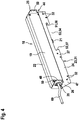
- the Figures 2 and 3 show an embodiment of a drive device 18, which is suitable to be connected to the public grid. This is done via a not shown in these two figures supply power cable.
- the supply voltage is for example 220 volts.
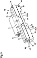
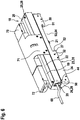
- the in the FIGS. 4 to 7 shown drive device 18 is suitable for a low-voltage operation, for example by low-voltage network and / or by means of accumulator or battery. For example, the supply voltage is 24 volts.
- the embodiments differ from the FIGS. 4 to 6 in that no or different additional controls 70 are used in this low-voltage variant. Corresponding additional controls 70 can also in the design according to the Figures 2 and 3 are used, but are not shown in these figures.
- the FIG. 4 shows the embodiment without additional control 70.
- FIG. 5 is the design according to FIG. 4 an additional control 70 assigned. It is fastened by means of an arcuate holder 71, which is screwed to the base wall 24 or - as in FIG. 5
- the rear wall 71 preferably connects the two wings 50 with each other, in particular such that the side walls 25 and 26 are integrally formed in the region of the wings 50 with the rear wall 71, wherein - in particular in the embodiment as Sheet metal console 31 - the mentioned parts are bent by 90 ° to each other by 90 °.
- additional units can be operated, for example, a rain sensor is connected and / or a roller shutter.
- the rain sensor senses a precipitate and causes the drive device 18 to close the canopy 1, if it is open. If a roller shutter of the residential roof window 1 is operated with the additional control 70, the sash frame 2 of the residential roof window 1 is first closed when the shutters are lowered, and only then is the roller shutter actuated.
- the FIG. 6 shows another embodiment of the additional controller 70, the mentioned functions according to FIG. 5 may also have, however, in addition to the operation of the drive means 18 via a solar cell array located on the canopy window and electricity generated from solar energy, which is stored in an accumulator of the auxiliary control 70 and allows operation without additional power supply. In addition, however, a low-voltage operation over the in FIG. 6 shown electrical cable 69 done.
- the additional controls 70 of Figures 5 and 6 have electrical connections 72 that allow connection to the aforementioned rain sensor, the roller shutter and / or the solar panel.
Landscapes
- Power-Operated Mechanisms For Wings (AREA)
Priority Applications (1)
| Application Number | Priority Date | Filing Date | Title |
|---|---|---|---|
| PL17169288T PL3241968T3 (pl) | 2016-05-04 | 2017-05-03 | Urządzenie napędowe do ramy skrzydła okna dachowego mieszkania, jak też okno dachowe mieszkania z urządzeniem napędowym |
Applications Claiming Priority (1)
| Application Number | Priority Date | Filing Date | Title |
|---|---|---|---|
| DE102016005507.3A DE102016005507B3 (de) | 2016-05-04 | 2016-05-04 | Antriebseinrichtung für einen Flügelrahmen eines Wohndachfensters sowie Wohndachfenster rnit Antriebseinrichtung |
Publications (2)
| Publication Number | Publication Date |
|---|---|
| EP3241968A1 EP3241968A1 (de) | 2017-11-08 |
| EP3241968B1 true EP3241968B1 (de) | 2019-01-09 |
Family
ID=58669670
Family Applications (1)
| Application Number | Title | Priority Date | Filing Date |
|---|---|---|---|
| EP17169288.2A Active EP3241968B1 (de) | 2016-05-04 | 2017-05-03 | Antriebseinrichtung für einen flügelrahmen eines wohndachfensters sowie wohndachfenster mit antriebseinrichtung |
Country Status (3)
| Country | Link |
|---|---|
| EP (1) | EP3241968B1 (pl) |
| DE (1) | DE102016005507B3 (pl) |
| PL (1) | PL3241968T3 (pl) |
Families Citing this family (1)
| Publication number | Priority date | Publication date | Assignee | Title |
|---|---|---|---|---|
| DE102019124021A1 (de) * | 2019-09-06 | 2021-03-11 | Iwis Antriebssysteme Gmbh & Co. Kg | Aktuator mit rückensteifer Kette |
Family Cites Families (5)
| Publication number | Priority date | Publication date | Assignee | Title |
|---|---|---|---|---|
| DE9309548U1 (de) * | 1993-06-26 | 1993-09-16 | GEZE GmbH, 71229 Leonberg | Antrieb für einen Flügel mit einem Motor mit abtriebsseitiger Motorstange |
| DK2034218T3 (da) * | 2007-08-28 | 2012-07-16 | Vkr Holding As | Tryk-trækkæde og aktuator |
| IT1398838B1 (it) * | 2010-03-19 | 2013-03-21 | Ultraflex Control Systems Srl | Sistema di attuazione dell'apertura e chiusura di ante |
| US20110302843A1 (en) * | 2010-06-11 | 2011-12-15 | Dallmann Brian D | Window drive with back-curving chain |
| DE202011000356U1 (de) * | 2011-02-16 | 2012-05-18 | D + H Mechatronic Aktiengesellschaft | Solarantrieb für ein bewegliches Gebäudeteil |
-
2016
- 2016-05-04 DE DE102016005507.3A patent/DE102016005507B3/de not_active Expired - Fee Related
-
2017
- 2017-05-03 EP EP17169288.2A patent/EP3241968B1/de active Active
- 2017-05-03 PL PL17169288T patent/PL3241968T3/pl unknown
Non-Patent Citations (1)
| Title |
|---|
| None * |
Also Published As
| Publication number | Publication date |
|---|---|
| EP3241968A1 (de) | 2017-11-08 |
| DE102016005507B3 (de) | 2017-09-07 |
| PL3241968T3 (pl) | 2019-07-31 |
Similar Documents
| Publication | Publication Date | Title |
|---|---|---|
| DE69224663T2 (de) | Fenster mit einem rahmen aus extrudierten profilen | |
| DE102006012176A1 (de) | Einstellbarer Fensterheber I | |
| DE102019211794A1 (de) | Baukasten für einen Laufwagen für einen Beschlag eines Schiebefensters oder einer Schiebetür | |
| DE10117173B4 (de) | Tür | |
| EP3241968B1 (de) | Antriebseinrichtung für einen flügelrahmen eines wohndachfensters sowie wohndachfenster mit antriebseinrichtung | |
| DE10117173A9 (de) | Tuer | |
| DE102011056416C5 (de) | Anordnung einer Antriebseinheit einer Ausstell- oder Verriegelungseinrichtung | |
| EP3183408B1 (de) | Steuerelement für eine beschlaganordnung | |
| EP2947229B1 (de) | Dachfenster sowie verfahren zum montieren eines dachfensters | |
| CH714546A2 (de) | Vorrichtung zum Öffnen einer Gebäudedachöffnung. | |
| EP1678402B1 (de) | Vorrichtung zur aufnahme des gewichtes einer ein- oder zweiflügeligen tür für einen schaltschrank | |
| EP3577295B1 (de) | Möbelantrieb zum bewegen eines bewegbar gelagerten möbelteiles | |
| EP3168394B1 (de) | Sperrkloben für einen türöffner oder ein schliessblech | |
| DE202012010009U1 (de) | Fenster mit Abschirmvorrichtung mit verbesserten Befestigungsvorrichtungen | |
| DE102015120712A1 (de) | Fenster zum Verschließen einer Gebäudeöffnung | |
| EP2740873A2 (de) | Zur verdeckten Anordnung vorgesehenes Ecklager und Fenster mit einem Ecklager | |
| EP2339095B1 (de) | Tür, insbesondere Kunstofftür, mit einer Schlosskastensicherung | |
| DE19648147C1 (de) | Motorisch angetriebene Kippöffnungs-Vorrichtung für Fenster oder Türen | |
| DE4209893C1 (de) | Vorrichtung zum Verschließen einer Öffnung in einer Dachfläche eines Schrägdaches | |
| DE102005051997B4 (de) | Tor | |
| DE102014112050B4 (de) | Baukastensystem einer Schließvorrichtung eines Gebäudes | |
| EP3133223B1 (de) | Terrassendach mit schwenkbarem vordach | |
| EP2105565B1 (de) | Antrieb für einen flügel eines fensters | |
| EP4105423B1 (de) | Scharniervorrichtung und faltschiebeladen damit | |
| DE102020101708A1 (de) | Befestigungsvorrichtung und Fassade |
Legal Events
| Date | Code | Title | Description |
|---|---|---|---|
| PUAI | Public reference made under article 153(3) epc to a published international application that has entered the european phase |
Free format text: ORIGINAL CODE: 0009012 |
|
| STAA | Information on the status of an ep patent application or granted ep patent |
Free format text: STATUS: THE APPLICATION HAS BEEN PUBLISHED |
|
| AK | Designated contracting states |
Kind code of ref document: A1 Designated state(s): AL AT BE BG CH CY CZ DE DK EE ES FI FR GB GR HR HU IE IS IT LI LT LU LV MC MK MT NL NO PL PT RO RS SE SI SK SM TR |
|
| AX | Request for extension of the european patent |
Extension state: BA ME |
|
| STAA | Information on the status of an ep patent application or granted ep patent |
Free format text: STATUS: REQUEST FOR EXAMINATION WAS MADE |
|
| 17P | Request for examination filed |
Effective date: 20180214 |
|
| RBV | Designated contracting states (corrected) |
Designated state(s): AL AT BE BG CH CY CZ DE DK EE ES FI FR GB GR HR HU IE IS IT LI LT LU LV MC MK MT NL NO PL PT RO RS SE SI SK SM TR |
|
| GRAP | Despatch of communication of intention to grant a patent |
Free format text: ORIGINAL CODE: EPIDOSNIGR1 |
|
| STAA | Information on the status of an ep patent application or granted ep patent |
Free format text: STATUS: GRANT OF PATENT IS INTENDED |
|
| INTG | Intention to grant announced |
Effective date: 20180727 |
|
| GRAS | Grant fee paid |
Free format text: ORIGINAL CODE: EPIDOSNIGR3 |
|
| GRAA | (expected) grant |
Free format text: ORIGINAL CODE: 0009210 |
|
| STAA | Information on the status of an ep patent application or granted ep patent |
Free format text: STATUS: THE PATENT HAS BEEN GRANTED |
|
| AK | Designated contracting states |
Kind code of ref document: B1 Designated state(s): AL AT BE BG CH CY CZ DE DK EE ES FI FR GB GR HR HU IE IS IT LI LT LU LV MC MK MT NL NO PL PT RO RS SE SI SK SM TR |
|
| REG | Reference to a national code |
Ref country code: GB Ref legal event code: FG4D Free format text: NOT ENGLISH |
|
| REG | Reference to a national code |
Ref country code: CH Ref legal event code: EP Ref country code: AT Ref legal event code: REF Ref document number: 1087508 Country of ref document: AT Kind code of ref document: T Effective date: 20190115 |
|
| REG | Reference to a national code |
Ref country code: IE Ref legal event code: FG4D Free format text: LANGUAGE OF EP DOCUMENT: GERMAN |
|
| REG | Reference to a national code |
Ref country code: DE Ref legal event code: R096 Ref document number: 502017000641 Country of ref document: DE |
|
| REG | Reference to a national code |
Ref country code: CH Ref legal event code: NV Representative=s name: OFFICE ERNEST T. FREYLINGER S.A., CH |
|
| REG | Reference to a national code |
Ref country code: NL Ref legal event code: MP Effective date: 20190109 |
|
| REG | Reference to a national code |
Ref country code: LT Ref legal event code: MG4D |
|
| PG25 | Lapsed in a contracting state [announced via postgrant information from national office to epo] |
Ref country code: NL Free format text: LAPSE BECAUSE OF FAILURE TO SUBMIT A TRANSLATION OF THE DESCRIPTION OR TO PAY THE FEE WITHIN THE PRESCRIBED TIME-LIMIT Effective date: 20190109 |
|
| PG25 | Lapsed in a contracting state [announced via postgrant information from national office to epo] |
Ref country code: PT Free format text: LAPSE BECAUSE OF FAILURE TO SUBMIT A TRANSLATION OF THE DESCRIPTION OR TO PAY THE FEE WITHIN THE PRESCRIBED TIME-LIMIT Effective date: 20190509 Ref country code: FI Free format text: LAPSE BECAUSE OF FAILURE TO SUBMIT A TRANSLATION OF THE DESCRIPTION OR TO PAY THE FEE WITHIN THE PRESCRIBED TIME-LIMIT Effective date: 20190109 Ref country code: SE Free format text: LAPSE BECAUSE OF FAILURE TO SUBMIT A TRANSLATION OF THE DESCRIPTION OR TO PAY THE FEE WITHIN THE PRESCRIBED TIME-LIMIT Effective date: 20190109 Ref country code: NO Free format text: LAPSE BECAUSE OF FAILURE TO SUBMIT A TRANSLATION OF THE DESCRIPTION OR TO PAY THE FEE WITHIN THE PRESCRIBED TIME-LIMIT Effective date: 20190409 Ref country code: ES Free format text: LAPSE BECAUSE OF FAILURE TO SUBMIT A TRANSLATION OF THE DESCRIPTION OR TO PAY THE FEE WITHIN THE PRESCRIBED TIME-LIMIT Effective date: 20190109 Ref country code: LT Free format text: LAPSE BECAUSE OF FAILURE TO SUBMIT A TRANSLATION OF THE DESCRIPTION OR TO PAY THE FEE WITHIN THE PRESCRIBED TIME-LIMIT Effective date: 20190109 |
|
| PG25 | Lapsed in a contracting state [announced via postgrant information from national office to epo] |
Ref country code: HR Free format text: LAPSE BECAUSE OF FAILURE TO SUBMIT A TRANSLATION OF THE DESCRIPTION OR TO PAY THE FEE WITHIN THE PRESCRIBED TIME-LIMIT Effective date: 20190109 Ref country code: RS Free format text: LAPSE BECAUSE OF FAILURE TO SUBMIT A TRANSLATION OF THE DESCRIPTION OR TO PAY THE FEE WITHIN THE PRESCRIBED TIME-LIMIT Effective date: 20190109 Ref country code: LV Free format text: LAPSE BECAUSE OF FAILURE TO SUBMIT A TRANSLATION OF THE DESCRIPTION OR TO PAY THE FEE WITHIN THE PRESCRIBED TIME-LIMIT Effective date: 20190109 Ref country code: IS Free format text: LAPSE BECAUSE OF FAILURE TO SUBMIT A TRANSLATION OF THE DESCRIPTION OR TO PAY THE FEE WITHIN THE PRESCRIBED TIME-LIMIT Effective date: 20190509 Ref country code: BG Free format text: LAPSE BECAUSE OF FAILURE TO SUBMIT A TRANSLATION OF THE DESCRIPTION OR TO PAY THE FEE WITHIN THE PRESCRIBED TIME-LIMIT Effective date: 20190409 Ref country code: GR Free format text: LAPSE BECAUSE OF FAILURE TO SUBMIT A TRANSLATION OF THE DESCRIPTION OR TO PAY THE FEE WITHIN THE PRESCRIBED TIME-LIMIT Effective date: 20190410 |
|
| REG | Reference to a national code |
Ref country code: DE Ref legal event code: R097 Ref document number: 502017000641 Country of ref document: DE |
|
| PG25 | Lapsed in a contracting state [announced via postgrant information from national office to epo] |
Ref country code: EE Free format text: LAPSE BECAUSE OF FAILURE TO SUBMIT A TRANSLATION OF THE DESCRIPTION OR TO PAY THE FEE WITHIN THE PRESCRIBED TIME-LIMIT Effective date: 20190109 Ref country code: DK Free format text: LAPSE BECAUSE OF FAILURE TO SUBMIT A TRANSLATION OF THE DESCRIPTION OR TO PAY THE FEE WITHIN THE PRESCRIBED TIME-LIMIT Effective date: 20190109 Ref country code: RO Free format text: LAPSE BECAUSE OF FAILURE TO SUBMIT A TRANSLATION OF THE DESCRIPTION OR TO PAY THE FEE WITHIN THE PRESCRIBED TIME-LIMIT Effective date: 20190109 Ref country code: IT Free format text: LAPSE BECAUSE OF FAILURE TO SUBMIT A TRANSLATION OF THE DESCRIPTION OR TO PAY THE FEE WITHIN THE PRESCRIBED TIME-LIMIT Effective date: 20190109 Ref country code: AL Free format text: LAPSE BECAUSE OF FAILURE TO SUBMIT A TRANSLATION OF THE DESCRIPTION OR TO PAY THE FEE WITHIN THE PRESCRIBED TIME-LIMIT Effective date: 20190109 Ref country code: SK Free format text: LAPSE BECAUSE OF FAILURE TO SUBMIT A TRANSLATION OF THE DESCRIPTION OR TO PAY THE FEE WITHIN THE PRESCRIBED TIME-LIMIT Effective date: 20190109 |
|
| PLBE | No opposition filed within time limit |
Free format text: ORIGINAL CODE: 0009261 |
|
| STAA | Information on the status of an ep patent application or granted ep patent |
Free format text: STATUS: NO OPPOSITION FILED WITHIN TIME LIMIT |
|
| 26N | No opposition filed |
Effective date: 20191010 |
|
| PG25 | Lapsed in a contracting state [announced via postgrant information from national office to epo] |
Ref country code: MC Free format text: LAPSE BECAUSE OF FAILURE TO SUBMIT A TRANSLATION OF THE DESCRIPTION OR TO PAY THE FEE WITHIN THE PRESCRIBED TIME-LIMIT Effective date: 20190109 |
|
| REG | Reference to a national code |
Ref country code: BE Ref legal event code: MM Effective date: 20190531 |
|
| PG25 | Lapsed in a contracting state [announced via postgrant information from national office to epo] |
Ref country code: LU Free format text: LAPSE BECAUSE OF NON-PAYMENT OF DUE FEES Effective date: 20190503 Ref country code: SI Free format text: LAPSE BECAUSE OF FAILURE TO SUBMIT A TRANSLATION OF THE DESCRIPTION OR TO PAY THE FEE WITHIN THE PRESCRIBED TIME-LIMIT Effective date: 20190109 |
|
| PG25 | Lapsed in a contracting state [announced via postgrant information from national office to epo] |
Ref country code: TR Free format text: LAPSE BECAUSE OF FAILURE TO SUBMIT A TRANSLATION OF THE DESCRIPTION OR TO PAY THE FEE WITHIN THE PRESCRIBED TIME-LIMIT Effective date: 20190109 |
|
| PG25 | Lapsed in a contracting state [announced via postgrant information from national office to epo] |
Ref country code: IE Free format text: LAPSE BECAUSE OF NON-PAYMENT OF DUE FEES Effective date: 20190503 |
|
| PG25 | Lapsed in a contracting state [announced via postgrant information from national office to epo] |
Ref country code: BE Free format text: LAPSE BECAUSE OF NON-PAYMENT OF DUE FEES Effective date: 20190531 |
|
| PG25 | Lapsed in a contracting state [announced via postgrant information from national office to epo] |
Ref country code: CY Free format text: LAPSE BECAUSE OF FAILURE TO SUBMIT A TRANSLATION OF THE DESCRIPTION OR TO PAY THE FEE WITHIN THE PRESCRIBED TIME-LIMIT Effective date: 20190109 |
|
| PG25 | Lapsed in a contracting state [announced via postgrant information from national office to epo] |
Ref country code: SM Free format text: LAPSE BECAUSE OF FAILURE TO SUBMIT A TRANSLATION OF THE DESCRIPTION OR TO PAY THE FEE WITHIN THE PRESCRIBED TIME-LIMIT Effective date: 20190109 |
|
| PG25 | Lapsed in a contracting state [announced via postgrant information from national office to epo] |
Ref country code: MT Free format text: LAPSE BECAUSE OF FAILURE TO SUBMIT A TRANSLATION OF THE DESCRIPTION OR TO PAY THE FEE WITHIN THE PRESCRIBED TIME-LIMIT Effective date: 20190109 Ref country code: HU Free format text: LAPSE BECAUSE OF FAILURE TO SUBMIT A TRANSLATION OF THE DESCRIPTION OR TO PAY THE FEE WITHIN THE PRESCRIBED TIME-LIMIT; INVALID AB INITIO Effective date: 20170503 |
|
| PG25 | Lapsed in a contracting state [announced via postgrant information from national office to epo] |
Ref country code: MK Free format text: LAPSE BECAUSE OF FAILURE TO SUBMIT A TRANSLATION OF THE DESCRIPTION OR TO PAY THE FEE WITHIN THE PRESCRIBED TIME-LIMIT Effective date: 20190109 |
|
| PGFP | Annual fee paid to national office [announced via postgrant information from national office to epo] |
Ref country code: PL Payment date: 20250422 Year of fee payment: 9 Ref country code: DE Payment date: 20250519 Year of fee payment: 9 |
|
| PGFP | Annual fee paid to national office [announced via postgrant information from national office to epo] |
Ref country code: GB Payment date: 20250522 Year of fee payment: 9 |
|
| PGFP | Annual fee paid to national office [announced via postgrant information from national office to epo] |
Ref country code: FR Payment date: 20250523 Year of fee payment: 9 |
|
| PGFP | Annual fee paid to national office [announced via postgrant information from national office to epo] |
Ref country code: CH Payment date: 20250601 Year of fee payment: 9 |
|
| PGFP | Annual fee paid to national office [announced via postgrant information from national office to epo] |
Ref country code: AT Payment date: 20250519 Year of fee payment: 9 |
|
| PGFP | Annual fee paid to national office [announced via postgrant information from national office to epo] |
Ref country code: CZ Payment date: 20250417 Year of fee payment: 9 |