EP3240175B1 - Vorrichtung zur steuerung des betriebs einer stromwandlervorrichtung - Google Patents
Vorrichtung zur steuerung des betriebs einer stromwandlervorrichtung Download PDFInfo
- Publication number
- EP3240175B1 EP3240175B1 EP16198611.2A EP16198611A EP3240175B1 EP 3240175 B1 EP3240175 B1 EP 3240175B1 EP 16198611 A EP16198611 A EP 16198611A EP 3240175 B1 EP3240175 B1 EP 3240175B1
- Authority
- EP
- European Patent Office
- Prior art keywords
- relay
- initial charging
- monitoring
- inverter
- reference voltage
- Prior art date
- Legal status (The legal status is an assumption and is not a legal conclusion. Google has not performed a legal analysis and makes no representation as to the accuracy of the status listed.)
- Active
Links
- 238000006243 chemical reaction Methods 0.000 title claims description 33
- 238000012544 monitoring process Methods 0.000 claims description 59
- 230000005856 abnormality Effects 0.000 claims description 12
- 230000007257 malfunction Effects 0.000 description 9
- 238000010586 diagram Methods 0.000 description 6
- 239000003990 capacitor Substances 0.000 description 5
- 238000000034 method Methods 0.000 description 4
- 230000015556 catabolic process Effects 0.000 description 2
- 238000010276 construction Methods 0.000 description 2
- 238000007796 conventional method Methods 0.000 description 1
- 230000001419 dependent effect Effects 0.000 description 1
Images


Classifications
-
- H—ELECTRICITY
- H02—GENERATION; CONVERSION OR DISTRIBUTION OF ELECTRIC POWER
- H02P—CONTROL OR REGULATION OF ELECTRIC MOTORS, ELECTRIC GENERATORS OR DYNAMO-ELECTRIC CONVERTERS; CONTROLLING TRANSFORMERS, REACTORS OR CHOKE COILS
- H02P29/00—Arrangements for regulating or controlling electric motors, appropriate for both AC and DC motors
- H02P29/02—Providing protection against overload without automatic interruption of supply
- H02P29/024—Detecting a fault condition, e.g. short circuit, locked rotor, open circuit or loss of load
- H02P29/025—Detecting a fault condition, e.g. short circuit, locked rotor, open circuit or loss of load the fault being a power interruption
-
- H—ELECTRICITY
- H02—GENERATION; CONVERSION OR DISTRIBUTION OF ELECTRIC POWER
- H02M—APPARATUS FOR CONVERSION BETWEEN AC AND AC, BETWEEN AC AND DC, OR BETWEEN DC AND DC, AND FOR USE WITH MAINS OR SIMILAR POWER SUPPLY SYSTEMS; CONVERSION OF DC OR AC INPUT POWER INTO SURGE OUTPUT POWER; CONTROL OR REGULATION THEREOF
- H02M5/00—Conversion of ac power input into ac power output, e.g. for change of voltage, for change of frequency, for change of number of phases
- H02M5/40—Conversion of ac power input into ac power output, e.g. for change of voltage, for change of frequency, for change of number of phases with intermediate conversion into dc
- H02M5/42—Conversion of ac power input into ac power output, e.g. for change of voltage, for change of frequency, for change of number of phases with intermediate conversion into dc by static converters
- H02M5/44—Conversion of ac power input into ac power output, e.g. for change of voltage, for change of frequency, for change of number of phases with intermediate conversion into dc by static converters using discharge tubes or semiconductor devices to convert the intermediate dc into ac
- H02M5/453—Conversion of ac power input into ac power output, e.g. for change of voltage, for change of frequency, for change of number of phases with intermediate conversion into dc by static converters using discharge tubes or semiconductor devices to convert the intermediate dc into ac using devices of a triode or transistor type requiring continuous application of a control signal
- H02M5/458—Conversion of ac power input into ac power output, e.g. for change of voltage, for change of frequency, for change of number of phases with intermediate conversion into dc by static converters using discharge tubes or semiconductor devices to convert the intermediate dc into ac using devices of a triode or transistor type requiring continuous application of a control signal using semiconductor devices only
-
- G—PHYSICS
- G01—MEASURING; TESTING
- G01R—MEASURING ELECTRIC VARIABLES; MEASURING MAGNETIC VARIABLES
- G01R1/00—Details of instruments or arrangements of the types included in groups G01R5/00 - G01R13/00 and G01R31/00
- G01R1/20—Modifications of basic electric elements for use in electric measuring instruments; Structural combinations of such elements with such instruments
- G01R1/203—Resistors used for electric measuring, e.g. decade resistors standards, resistors for comparators, series resistors, shunts
-
- G—PHYSICS
- G01—MEASURING; TESTING
- G01R—MEASURING ELECTRIC VARIABLES; MEASURING MAGNETIC VARIABLES
- G01R19/00—Arrangements for measuring currents or voltages or for indicating presence or sign thereof
- G01R19/165—Indicating that current or voltage is either above or below a predetermined value or within or outside a predetermined range of values
- G01R19/16504—Indicating that current or voltage is either above or below a predetermined value or within or outside a predetermined range of values characterised by the components employed
- G01R19/16523—Indicating that current or voltage is either above or below a predetermined value or within or outside a predetermined range of values characterised by the components employed using diodes, e.g. Zener diodes
-
- G—PHYSICS
- G01—MEASURING; TESTING
- G01R—MEASURING ELECTRIC VARIABLES; MEASURING MAGNETIC VARIABLES
- G01R19/00—Arrangements for measuring currents or voltages or for indicating presence or sign thereof
- G01R19/165—Indicating that current or voltage is either above or below a predetermined value or within or outside a predetermined range of values
- G01R19/16566—Circuits and arrangements for comparing voltage or current with one or several thresholds and for indicating the result not covered by subgroups G01R19/16504, G01R19/16528, G01R19/16533
- G01R19/16576—Circuits and arrangements for comparing voltage or current with one or several thresholds and for indicating the result not covered by subgroups G01R19/16504, G01R19/16528, G01R19/16533 comparing DC or AC voltage with one threshold
-
- G—PHYSICS
- G01—MEASURING; TESTING
- G01R—MEASURING ELECTRIC VARIABLES; MEASURING MAGNETIC VARIABLES
- G01R19/00—Arrangements for measuring currents or voltages or for indicating presence or sign thereof
- G01R19/165—Indicating that current or voltage is either above or below a predetermined value or within or outside a predetermined range of values
- G01R19/16566—Circuits and arrangements for comparing voltage or current with one or several thresholds and for indicating the result not covered by subgroups G01R19/16504, G01R19/16528, G01R19/16533
- G01R19/1659—Circuits and arrangements for comparing voltage or current with one or several thresholds and for indicating the result not covered by subgroups G01R19/16504, G01R19/16528, G01R19/16533 to indicate that the value is within or outside a predetermined range of values (window)
-
- G—PHYSICS
- G01—MEASURING; TESTING
- G01R—MEASURING ELECTRIC VARIABLES; MEASURING MAGNETIC VARIABLES
- G01R31/00—Arrangements for testing electric properties; Arrangements for locating electric faults; Arrangements for electrical testing characterised by what is being tested not provided for elsewhere
- G01R31/327—Testing of circuit interrupters, switches or circuit-breakers
- G01R31/3277—Testing of circuit interrupters, switches or circuit-breakers of low voltage devices, e.g. domestic or industrial devices, such as motor protections, relays, rotation switches
- G01R31/3278—Testing of circuit interrupters, switches or circuit-breakers of low voltage devices, e.g. domestic or industrial devices, such as motor protections, relays, rotation switches of relays, solenoids or reed switches
-
- H—ELECTRICITY
- H02—GENERATION; CONVERSION OR DISTRIBUTION OF ELECTRIC POWER
- H02H—EMERGENCY PROTECTIVE CIRCUIT ARRANGEMENTS
- H02H7/00—Emergency protective circuit arrangements specially adapted for specific types of electric machines or apparatus or for sectionalised protection of cable or line systems, and effecting automatic switching in the event of an undesired change from normal working conditions
- H02H7/10—Emergency protective circuit arrangements specially adapted for specific types of electric machines or apparatus or for sectionalised protection of cable or line systems, and effecting automatic switching in the event of an undesired change from normal working conditions for converters; for rectifiers
- H02H7/12—Emergency protective circuit arrangements specially adapted for specific types of electric machines or apparatus or for sectionalised protection of cable or line systems, and effecting automatic switching in the event of an undesired change from normal working conditions for converters; for rectifiers for static converters or rectifiers
- H02H7/1216—Emergency protective circuit arrangements specially adapted for specific types of electric machines or apparatus or for sectionalised protection of cable or line systems, and effecting automatic switching in the event of an undesired change from normal working conditions for converters; for rectifiers for static converters or rectifiers for AC-AC converters
-
- H—ELECTRICITY
- H02—GENERATION; CONVERSION OR DISTRIBUTION OF ELECTRIC POWER
- H02H—EMERGENCY PROTECTIVE CIRCUIT ARRANGEMENTS
- H02H7/00—Emergency protective circuit arrangements specially adapted for specific types of electric machines or apparatus or for sectionalised protection of cable or line systems, and effecting automatic switching in the event of an undesired change from normal working conditions
- H02H7/10—Emergency protective circuit arrangements specially adapted for specific types of electric machines or apparatus or for sectionalised protection of cable or line systems, and effecting automatic switching in the event of an undesired change from normal working conditions for converters; for rectifiers
- H02H7/12—Emergency protective circuit arrangements specially adapted for specific types of electric machines or apparatus or for sectionalised protection of cable or line systems, and effecting automatic switching in the event of an undesired change from normal working conditions for converters; for rectifiers for static converters or rectifiers
- H02H7/122—Emergency protective circuit arrangements specially adapted for specific types of electric machines or apparatus or for sectionalised protection of cable or line systems, and effecting automatic switching in the event of an undesired change from normal working conditions for converters; for rectifiers for static converters or rectifiers for inverters, i.e. dc/ac converters
-
- H—ELECTRICITY
- H02—GENERATION; CONVERSION OR DISTRIBUTION OF ELECTRIC POWER
- H02H—EMERGENCY PROTECTIVE CIRCUIT ARRANGEMENTS
- H02H9/00—Emergency protective circuit arrangements for limiting excess current or voltage without disconnection
-
- H—ELECTRICITY
- H02—GENERATION; CONVERSION OR DISTRIBUTION OF ELECTRIC POWER
- H02H—EMERGENCY PROTECTIVE CIRCUIT ARRANGEMENTS
- H02H9/00—Emergency protective circuit arrangements for limiting excess current or voltage without disconnection
- H02H9/001—Emergency protective circuit arrangements for limiting excess current or voltage without disconnection limiting speed of change of electric quantities, e.g. soft switching on or off
- H02H9/004—Emergency protective circuit arrangements for limiting excess current or voltage without disconnection limiting speed of change of electric quantities, e.g. soft switching on or off in connection with live-insertion of plug-in units
-
- H—ELECTRICITY
- H02—GENERATION; CONVERSION OR DISTRIBUTION OF ELECTRIC POWER
- H02M—APPARATUS FOR CONVERSION BETWEEN AC AND AC, BETWEEN AC AND DC, OR BETWEEN DC AND DC, AND FOR USE WITH MAINS OR SIMILAR POWER SUPPLY SYSTEMS; CONVERSION OF DC OR AC INPUT POWER INTO SURGE OUTPUT POWER; CONTROL OR REGULATION THEREOF
- H02M1/00—Details of apparatus for conversion
- H02M1/08—Circuits specially adapted for the generation of control voltages for semiconductor devices incorporated in static converters
-
- H—ELECTRICITY
- H02—GENERATION; CONVERSION OR DISTRIBUTION OF ELECTRIC POWER
- H02M—APPARATUS FOR CONVERSION BETWEEN AC AND AC, BETWEEN AC AND DC, OR BETWEEN DC AND DC, AND FOR USE WITH MAINS OR SIMILAR POWER SUPPLY SYSTEMS; CONVERSION OF DC OR AC INPUT POWER INTO SURGE OUTPUT POWER; CONTROL OR REGULATION THEREOF
- H02M1/00—Details of apparatus for conversion
- H02M1/32—Means for protecting converters other than automatic disconnection
- H02M1/34—Snubber circuits
-
- H—ELECTRICITY
- H02—GENERATION; CONVERSION OR DISTRIBUTION OF ELECTRIC POWER
- H02M—APPARATUS FOR CONVERSION BETWEEN AC AND AC, BETWEEN AC AND DC, OR BETWEEN DC AND DC, AND FOR USE WITH MAINS OR SIMILAR POWER SUPPLY SYSTEMS; CONVERSION OF DC OR AC INPUT POWER INTO SURGE OUTPUT POWER; CONTROL OR REGULATION THEREOF
- H02M7/00—Conversion of ac power input into dc power output; Conversion of dc power input into ac power output
- H02M7/42—Conversion of dc power input into ac power output without possibility of reversal
- H02M7/44—Conversion of dc power input into ac power output without possibility of reversal by static converters
- H02M7/48—Conversion of dc power input into ac power output without possibility of reversal by static converters using discharge tubes with control electrode or semiconductor devices with control electrode
-
- H—ELECTRICITY
- H02—GENERATION; CONVERSION OR DISTRIBUTION OF ELECTRIC POWER
- H02P—CONTROL OR REGULATION OF ELECTRIC MOTORS, ELECTRIC GENERATORS OR DYNAMO-ELECTRIC CONVERTERS; CONTROLLING TRANSFORMERS, REACTORS OR CHOKE COILS
- H02P1/00—Arrangements for starting electric motors or dynamo-electric converters
- H02P1/02—Details of starting control
- H02P1/04—Means for controlling progress of starting sequence in dependence upon time or upon current, speed, or other motor parameter
-
- H—ELECTRICITY
- H02—GENERATION; CONVERSION OR DISTRIBUTION OF ELECTRIC POWER
- H02P—CONTROL OR REGULATION OF ELECTRIC MOTORS, ELECTRIC GENERATORS OR DYNAMO-ELECTRIC CONVERTERS; CONTROLLING TRANSFORMERS, REACTORS OR CHOKE COILS
- H02P27/00—Arrangements or methods for the control of AC motors characterised by the kind of supply voltage
- H02P27/04—Arrangements or methods for the control of AC motors characterised by the kind of supply voltage using variable-frequency supply voltage, e.g. inverter or converter supply voltage
- H02P27/06—Arrangements or methods for the control of AC motors characterised by the kind of supply voltage using variable-frequency supply voltage, e.g. inverter or converter supply voltage using dc to ac converters or inverters
- H02P27/08—Arrangements or methods for the control of AC motors characterised by the kind of supply voltage using variable-frequency supply voltage, e.g. inverter or converter supply voltage using dc to ac converters or inverters with pulse width modulation
- H02P27/085—Arrangements or methods for the control of AC motors characterised by the kind of supply voltage using variable-frequency supply voltage, e.g. inverter or converter supply voltage using dc to ac converters or inverters with pulse width modulation wherein the PWM mode is adapted on the running conditions of the motor, e.g. the switching frequency
-
- H—ELECTRICITY
- H02—GENERATION; CONVERSION OR DISTRIBUTION OF ELECTRIC POWER
- H02M—APPARATUS FOR CONVERSION BETWEEN AC AND AC, BETWEEN AC AND DC, OR BETWEEN DC AND DC, AND FOR USE WITH MAINS OR SIMILAR POWER SUPPLY SYSTEMS; CONVERSION OF DC OR AC INPUT POWER INTO SURGE OUTPUT POWER; CONTROL OR REGULATION THEREOF
- H02M1/00—Details of apparatus for conversion
- H02M1/32—Means for protecting converters other than automatic disconnection
- H02M1/34—Snubber circuits
- H02M1/346—Passive non-dissipative snubbers
-
- Y—GENERAL TAGGING OF NEW TECHNOLOGICAL DEVELOPMENTS; GENERAL TAGGING OF CROSS-SECTIONAL TECHNOLOGIES SPANNING OVER SEVERAL SECTIONS OF THE IPC; TECHNICAL SUBJECTS COVERED BY FORMER USPC CROSS-REFERENCE ART COLLECTIONS [XRACs] AND DIGESTS
- Y02—TECHNOLOGIES OR APPLICATIONS FOR MITIGATION OR ADAPTATION AGAINST CLIMATE CHANGE
- Y02B—CLIMATE CHANGE MITIGATION TECHNOLOGIES RELATED TO BUILDINGS, e.g. HOUSING, HOUSE APPLIANCES OR RELATED END-USER APPLICATIONS
- Y02B70/00—Technologies for an efficient end-user side electric power management and consumption
- Y02B70/10—Technologies improving the efficiency by using switched-mode power supplies [SMPS], i.e. efficient power electronics conversion e.g. power factor correction or reduction of losses in power supplies or efficient standby modes
Definitions
- the present invention relates to an apparatus for controlling the operation of a power conversion device such as an inverter or a converter.
- An inverter and a converter are representative of power conversion devices.
- the inverter is a device which converts input AC power into DC power and then again converts the DC power into AC power when is then supplied to a load such as a motor.
- the inverter is utilized for a variety of products such as a fan, pump, elevator, conveyer, production line and so on.
- a general-purpose inverter for motor driving converts three-phase AC power into DC power through a rectifier, stores the DC power in a capacitor of a DC-link part, and then converts the stored DC power into AC power through an inverter part.
- the converter is a power conversion device, which converts input AC or DC power into DC power.
- the converter converts power in the way similar to the converter and is likewise utilized in various ways throughout the industry.
- US 3 631 332 discloses a background art power conversion device comprising control circuits for controlling operation of the power conversion device.
- JP 3 521337 B2 discloses: "An apparatus for controlling the operation of a power conversion device including a rectifier part, an initial charging part, a DC-link part and an inverter part, the apparatus comprising: a control part configured to drive a relay connected in parallel to an initial charging resistor of the initial charging part if a DC-link voltage of the DC-link part exceeds a first reference voltage during initial charging for the DC-link part; a relay monitoring part configured to monitor whether or not the relay is normally being operated based on a second reference voltage and voltage measured across the initial charging resistor when the relay is driven; and an inverter driving part configured to stop the driving of the inverter part if it is determined that the relay is not normally being operated by referring to a result of the monitoring of the relay monitoring part; the relay monitoring part is configured to output a first monitoring signal when a voltage measured across the initial charging resistor exceeds a second reference voltage, and to output a second monitoring signal when the voltage does not exceed the second reference voltage".
- Fig. 1 is a view illustrating the configuration of a conventional power conversion device.
- a power conversion device such as, e.g., an inverter 104 receives three-phase AC power from a power supply 102 and converts it into DC power through a rectifier part 108.
- the obtained DC power is stored in a capacitor of a DC-link part 116 and is converted into AC power having a predetermined frequency through an inverter part 120.
- the AC power obtained thus is supplied to a load 106 such as a motor.
- the inverter 104 illustrated in Fig. 1 controls a driving speed of the load 106 by varying a voltage and a frequency according to a PWM (Pulse Width Modulation) output using switching elements T1 to T6 included in the inverter part 120.
- PWM Pulse Width Modulation
- An initial charging part 110 is applied to the inverter system as shown in Fig. 1 .
- the initial charging part 110 is provided to prevent an overcurrent from occurring due to an inrush current input to the inverter 104, thereby preventing dielectric breakdown of an element.
- An initial charging resistor 112 of the initial charging part 110 is operated only when the inverter 104 is initially powered on. After completing the initial charging operation, the initial charging part 110 switches a flow of current to a relay 114 to prevent an unnecessary power loss by the initial charging resistor 112.
- a controller 10 as shown in Fig. 1 is used to control such an operation of the inverter 104.
- the controller 10 includes a control part 12 and an inverter driving part 14.
- the control part 12 controls a current to be flown through the initial charging resistor 112, thereby charging the capacitor of the DC-link part 116 with a voltage.
- the control part 12 measures a voltage Vdc of the DC-link part 116 and determines whether or not the measured voltage Vdc exceeds a preset reference voltage. If the measured voltage Vdc does not exceed a preset reference voltage, the control part 12 generates a low voltage trip (LVT) to limit the operation of the relay 114 included in the initial charging part 110.
- LVT low voltage trip
- the term "low voltage trip (LVT)" used herein means a signal indicating that the voltage Vdc of the DC-link part 116 does not exceed the preset reference voltage.
- the control part 12 can inform the relay 114 or other module that the voltage Vdc of the DC-link part 116 does not exceed the preset reference voltage through the LVT signal. In other words, upon receiving the LVT signal, the relay 114 or other module can recognize that the voltage Vdc of the DC-link part 116 does not exceed the preset reference voltage.
- the control part 12 releases the LVT to drive the relay 114. Accordingly, a current is flown into the relay 114 rather than the initial charging resistor 112.
- control part 12 controls the inverter driving part 14 to generate a PWM signal to drive the inverter 104.
- the relay 114 if the relay 114 is not normally driven due to occurrence of abnormality, the current continues to be flown through the initial charging resistor 112 despite the release of the LVT by the control part 12. At this time, if the load 106 connected to the inverter 104 can be driven only with a small current flown through the initial charging resistor 112, the voltage Vdc of the DC-link part 116 does not fall below the preset reference voltage. Accordingly, even though abnormality occurs in the relay 114, a user cannot detect the abnormality of the relay 114. In this manner, when the current continues to be flown through the initial charging resistor 112 even after the initial charging operation is ended, the relay 114 may be damaged due to overheat, which may result in impossibility of use of the power conversion device.
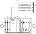
- Fig. 2 is a view illustrating the configuration of a power conversion device and an apparatus for controlling the operation of the power conversion device according to one embodiment of the present invention.
- a power conversion device will be illustrated with an inverter.
- the power conversion device is illustrated with an inverter 204, the apparatus for controlling the operation of the power conversion device of the present invention may be applied to a converter instead of the inverter.
- a power conversion device such as, e.g., the inverter 204 receives three-phase AC power from a power supply 202 and converts it into DC power through a rectifier part 208.
- the obtained DC power is stored in a capacitor of a DC-link part 216 and is converted into AC power having a predetermined frequency through an inverter part 220.
- the AC power obtained thus is supplied to a load 206 such as a motor.
- the inverter 204 illustrated in Fig. 2 controls a driving speed of the load 206 by varying a voltage and a frequency according to a PWM output using switching elements T1 to T6 included in the inverter part 120.
- An initial charging part 210 is applied to the inverter system as shown in Fig. 2 .
- the initial charging part 210 is provided to prevent an overcurrent from occurring due to an inrush current input to the inverter 204, thereby preventing dielectric breakdown of an element.
- An initial charging resistor 212 of the initial charging part 210 is operated only when the inverter 204 is initially powered on. After completing the initial charging operation, the initial charging part 210 switches a flow of current to a relay 214 to prevent an unnecessary power loss by the initial charging resistor 212.
- an apparatus 20 for controlling the operation of the power conversion device according to one embodiment of the present invention includes a control part 22, a relay monitoring part 24 and an inverter driving part 16.
- the apparatus 20 for controlling the operation of the power conversion device according to one embodiment of the present invention may further include a trip generator (not shown).
- the control part 22 controls a current input to the initial charging part 210 to be flown through one of the initial charging resistor 212 and the relay 214. To this end, the control part 22 may drive the relay 214 through a relay operation signal (MC). If the relay operation signal (MC) is not applied by the control part 22, the relay 214 is not driven and the current input to the initial charging part 210 is flown through the initial charging resistor 212. If the relay operation signal (MC) is applied by the control part 22, the relay 214 is driven and the current input to the initial charging part 210 is flown through the relay 214.
- MC relay operation signal
- control part 22 may monitor (or measure) a voltage Vdc of the DC-link part 216 during initial charging for the DC-link part 216. If the measured voltage Vdc exceeds a preset first reference voltage, the control part 22 drives the relay 214 connected in parallel to the initial charging resistor 212 of the initial charging part 210.
- the relay monitoring part 24 monitors whether or not the relay 214 is normally being operated. In one embodiment of the present invention, if the relay 214 is normally being operated, the relay monitoring part 24 outputs a first monitoring signal (e.g., a signal of a high level). Otherwise, the relay monitoring part 24 outputs a second monitoring signal (e.g., a signal of a low level).
- a first monitoring signal e.g., a signal of a high level. Otherwise, the relay monitoring part 24 outputs a second monitoring signal (e.g., a signal of a low level).
- the control part 22 determines whether or not the relay 214 is normally being operated, based on a monitoring signal output from the relay monitoring part 24. If it is determined that the relay 214 is not normally being operated, the control part 22 transmits a relay malfunction signal (MCT) to the inverter driving part 26. Upon receiving the relay malfunction signal (MCT), the inverter driving part 26 stops the driving of the inverter part 220 by not applying a PWM signal to the gates of the switching elements T1 to T6 included in the inverter part 220. Conversely, upon not receiving the relay malfunction signal (MCT), the inverter driving part 26 drives the inverter part 220 by applying the PWM signal to the gates of the switching elements T1 to T6 included in the inverter part 220.
- MCT relay malfunction signal
- the trip generator (not shown) delivers trip information to a user.
- the trip generator may inform the user of abnormality of the relay 214 by delivering the tip information to the user through a display of a user terminal.
- the trip generator may inform the user of abnormality of the relay 214 by sounding a sound through a speaker of the user terminal.
- Fig. 4 is a flow chart of a method for controlling the operation of the power conversion device according to one embodiment of the present invention.
- the control part 22 drives the power supply 202 to apply power to the inverter 204 (402). Accordingly, power output from the rectifier part 208 is stored in the capacitor of the DC-link part 216 via the initial charging part 210. This process continues until a voltage Vdc of the DC-link part 216 exceeds the preset first reference voltage, which is also called "initial charging operation.” In the initial charging operation, the control part 22 does not drive the relay 214 and a current is flown through the initial charging resistor 212.
- the control part 22 determines whether or not the DC-link voltage Vdc exceeds the preset first reference voltage (404).
- the first reference voltage may be arbitrarily set by a user.
- the control part 22 prevents the relay 214 from being driven by generating a low voltage trip (LVT). Accordingly, the current continues to be flown through the initial charging resistor 212.
- the control part 22 releases the low voltage trip (LVT). Accordingly, the relay operation signal (MC) is delivered to the relay 214 and the relay 214 is driven (406). At this time, the current is flown through the relay 214 rather than the initial charging resistor 212.
- the relay monitoring part 24 monitors whether or not the relay 214 is actually normally being operated (408). In one embodiment of the present invention, if a voltage measured across the initial charging resistor 212 exceeds a preset second reference voltage, the relay monitoring part 24 outputs the first monitoring signal. Otherwise, the relay monitoring part 24 outputs the second monitoring signal.
- the second reference voltage may be set arbitrarily by the user. In this manner, the control part 22 can determine whether or not the relay 214 is normally being operated, by referring to a monitoring signal (MCM), i.e., the first monitoring signal or the second monitoring signal, output by the relay monitoring part 24.
- MCM monitoring signal
- the relay monitoring part 24 may set the second reference voltage based on the resistance of the initial charging resistor 212. More specifically, the relay monitoring part can set the second reference voltage in inverse proportion to the resistance of the initial charging resistor 212. Accordingly, the relay monitoring part 214 can set the second reference voltage in consideration of situations where a voltage is applied as a small current is flown due to a small resistance of the initial charging resistor 212 even when the relay 214 is normally driven.
- Fig. 3 is a circuit diagram illustrating a relay monitoring part of the apparatus for controlling the operation of the power conversion device according to one embodiment of the present invention.
- the relay monitoring part of the apparatus for controlling the operation of the power conversion device includes a current limiting resistor R1 connected in parallel to the initial charging resistor 212, and a photo coupler 302 connected in series to the current limiting resistor R1.
- An input terminal P1 and an input terminal P2 shown in Fig. 3 are connected to both ends of the initial charging resistor 212, respectively, as shown in Fig. 2 .
- the photo coupler 302 Based on a result of comparison between the voltage measured across the initial charging resistor 212 through the input terminal P1 and the input terminal P2 and the second reference voltage input through an input terminal P3, the photo coupler 302 outputs the first monitoring signal (e.g., a high level signal) or the second monitoring signal (e.g., a low level signal) through an output terminal 304.
- the first monitoring signal e.g., a high level signal
- the second monitoring signal e.g., a low level signal
- the photo coupler 302 of Fig. 3 is turned off and the first monitoring signal (e.g., a high level signal) is output through the output terminal 304.
- the photo coupler 302 of Fig. 3 is turned on and the second monitoring signal (e.g., a low level signal) is output through the output terminal 304.
- the control part 22 can determine whether or not a current is actually normally flown through the relay 214 when the relay 214 is driven.
- control part 22 determines whether or not the relay 214 is normally being operated, by referring to the monitoring signal output from the relay monitoring part 24 (410).
- the control part 22 delivers the relay malfunction signal (MCT) to the inverter driving part 26.
- MCT relay malfunction signal
- the inverter driving part 26 stops the driving of the inverter part 220 by not applying a PWM signal to the gates of the switching elements T1 to T6 included in the inverter part 220 (412).
- the control part 22 does not deliver the relay malfunction signal (MCT) to the inverter driving part 26.
- the inverter driving part 26 drives the inverter part 220 by applying the PWM signal to the gates of the switching elements T1 to T6 included in the inverter part 220.
- the trip generator (not shown) delivers trip information to a user.
- the trip generator may inform the user of abnormality of the relay 214 by delivering the tip information to the user through a display of a user terminal.
- the trip generator may inform the user of abnormality of the relay 214 by sounding a sound through a speaker of the user terminal.
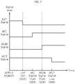
- Fig. 5 is a timing diagram of some signals produced when the relay is normally operated in one embodiment of the present invention.
- the low voltage trip (LVT) is released (502).
- the control part 22 delivers the relay operation signal (MC) to the relay 214 (504). Accordingly, the relay 214 begins to be operated.
- the relay monitoring part 24 When the relay 214 is normally operated according to the relay operation signal (MC), a current is flown through the relay 214 rather than the initial charging resistor 212. Accordingly, the relay monitoring part 24 outputs a high level signal, i.e., the first monitoring signal, as a monitoring signal (MCM) (506). Since it is checked that the relay 214 is normally being operated, the control part 22 does not output the relay malfunction signal (MCT) (508).
- MCM monitoring signal
- Fig. 6 is a timing diagram of some signals produced when abnormality occurs in the relay in one embodiment of the present invention.
- the low voltage trip (LVT) is released (602).
- the control part 22 delivers the relay operation signal (MC) to the relay 214 (604). Accordingly, the relay 214 begins to be operated.
- the relay monitoring part 24 outputs a low level signal, i.e., the second monitoring signal, as a monitoring signal (MCM) (606). Since it is checked that the relay 214 is not normally being operated, the control part 22 outputs the relay malfunction signal (MCT) (508). Accordingly, the driving of the inverter part 220 is stopped.
- MCM monitoring signal
Landscapes
- Engineering & Computer Science (AREA)
- Power Engineering (AREA)
- Physics & Mathematics (AREA)
- General Physics & Mathematics (AREA)
- Computer Hardware Design (AREA)
- Microelectronics & Electronic Packaging (AREA)
- Inverter Devices (AREA)
Claims (3)
- Vorrichtung zum Steuern des Betriebs einer Leistungsumwandlungsvorrichtung mit einem Gleichrichterteil (208), einem Anfangsladeteil (210), einem Gleichstromverbindungsteil (216) und einem Wechselrichterteil (220),
die Vorrichtung umfassend:einen Steuerteil (22), der konfiguriert ist, um ein Relais (214) anzusteuern, das parallel zu einem anfänglichen Ladewiderstand (212) des Anfangsladeteils (210) geschaltet ist, wenn eine Gleichstromverbindungsspannung des Gleichstromverbindungsteils (216) eine erste Referenzspannung während des anfänglichen Ladens für den Gleichstromverbindungsteil (216) überschreitet;einen Relaisüberwachungsteil (24), der konfiguriert ist, um zu überwachen, ob das Relais (214) normal betrieben wird oder nicht, basierend auf einer zweiten Referenzspannung und einer Spannung, die über dem anfänglichen Ladewiderstand gemessen wird, wenn das Relais (214) angesteuert wird; undein Wechselrichter-Ansteuerteil (26), der konfiguriert ist, um das Ansteuern des Wechselrichterteils (220) zu stoppen, wenn unter Bezugnahme auf ein Ergebnis der Überwachung des Relais-Überwachungsteils (24) festgestellt wird, dass das Relais (214) nicht normal betrieben wird,wobei,der Relais-Überwachungsteil (24) einen mit dem anfänglichen Ladewiderstand (212) verbundenen Strombegrenzungswiderstand (R1) und einen mit dem Strombegrenzungswiderstand (R1) verbundenen Fotokoppler (302) aufweist,dass der Relais-Überwachungsteil (24) konfiguriert ist, um die zweite Referenzspannung basierend auf dem Widerstand des anfänglichen Ladewiderstandes (212) einzustellen, unddass der Relais-Überwachungsteil so konfiguriert ist, dass er ein erstes Überwachungssignal ausgibt, wenn eine am anfänglichen Ladewiderstand (212) gemessene Spannung eine zweite Referenzspannung überschreitet, undein zweites Überwachungssignal auszugeben, wenn die Spannung die zweite Referenzspannung nicht überschreitet,wobei der Relais-Überwachungsteil (24) so konfiguriert ist, dass er die zweite Referenzspannung umgekehrt proportional zum Widerstandswert des anfänglichen Ladewiderstands (212) einstellt, undwobei das erste Überwachungssignal anzeigt, dass das Relais (214) normal betrieben wird, und das zweite Überwachungssignal anzeigt, dass das Relais (214) nicht normal betrieben wird. - Vorrichtung nach Anspruch 1, wobei der Steuerteil (22) konfiguriert ist, um einen anfänglichen Ladevorgang für den Gleichstromverbindungsteil (216) über den anfänglichen Ladewiderstand (212) durchzuführen.
- Vorrichtung nach Anspruch 1, ferner mit einem Auslösegenerator, der konfiguriert ist, um einem Benutzer eine Abnormalitätsausgabeinformation zu liefern, wenn das Relais (214) unter Bezugnahme auf ein Ergebnis der Überwachung des Relais-Überwachungsteils (24) nicht normal betrieben wird.
Applications Claiming Priority (1)
| Application Number | Priority Date | Filing Date | Title |
|---|---|---|---|
| KR1020160051148A KR102526874B1 (ko) | 2016-04-26 | 2016-04-26 | 전력 변환 장치의 동작 제어 장치 |
Publications (2)
| Publication Number | Publication Date |
|---|---|
| EP3240175A1 EP3240175A1 (de) | 2017-11-01 |
| EP3240175B1 true EP3240175B1 (de) | 2019-10-02 |
Family
ID=57326214
Family Applications (1)
| Application Number | Title | Priority Date | Filing Date |
|---|---|---|---|
| EP16198611.2A Active EP3240175B1 (de) | 2016-04-26 | 2016-11-14 | Vorrichtung zur steuerung des betriebs einer stromwandlervorrichtung |
Country Status (6)
| Country | Link |
|---|---|
| US (1) | US10003296B2 (de) |
| EP (1) | EP3240175B1 (de) |
| JP (1) | JP6400658B2 (de) |
| KR (1) | KR102526874B1 (de) |
| CN (1) | CN107317485B (de) |
| ES (1) | ES2760648T3 (de) |
Families Citing this family (7)
| Publication number | Priority date | Publication date | Assignee | Title |
|---|---|---|---|---|
| JP6559970B2 (ja) * | 2014-11-05 | 2019-08-14 | 三星電子株式会社Samsung Electronics Co.,Ltd. | コンバータ装置、インバータ装置及び交流機駆動装置 |
| JP6128201B1 (ja) * | 2015-12-28 | 2017-05-17 | ダイキン工業株式会社 | 電源装置、その電源装置を用いたインバータ装置、並びにコンバータ装置、及びそのインバータ装置又はコンバータ装置を用いた冷凍装置、並びに空気清浄器 |
| KR102007851B1 (ko) * | 2017-01-24 | 2019-10-21 | 엘지전자 주식회사 | 전력변환장치 및 이를 포함하는 공기조화장치 |
| KR102022977B1 (ko) * | 2018-02-26 | 2019-09-19 | 엘에스산전 주식회사 | 인버터 제어장치 및 방법 |
| JP6711859B2 (ja) * | 2018-04-04 | 2020-06-17 | ファナック株式会社 | モータ駆動装置およびモータ駆動装置の異常発熱検出方法 |
| KR102520182B1 (ko) * | 2020-02-24 | 2023-04-07 | 엘에스일렉트릭(주) | 인버터 초기충전회로의 고장진단장치 및 그 방법 |
| KR20220118813A (ko) * | 2021-02-19 | 2022-08-26 | 삼성전자주식회사 | 전원 공급 장치, 전자 장치, 및 그 제어 방법 |
Family Cites Families (21)
| Publication number | Priority date | Publication date | Assignee | Title |
|---|---|---|---|---|
| CA912109A (en) * | 1970-04-14 | 1972-10-10 | Canadian General Electric Company Limited | Inverter starting circuit |
| JPH06245485A (ja) * | 1993-02-18 | 1994-09-02 | Toshiba Corp | インバータ装置 |
| JPH0723523A (ja) * | 1993-06-30 | 1995-01-24 | Juki Corp | 突入防止回路の故障検出装置 |
| JP3521337B2 (ja) * | 1995-01-09 | 2004-04-19 | 三菱電機株式会社 | 空気調和機の制御装置 |
| JPH08317660A (ja) * | 1995-05-18 | 1996-11-29 | Fuji Electric Co Ltd | 電力変換装置の保護回路 |
| JPH10136129A (ja) * | 1996-10-30 | 1998-05-22 | Oki Electric Ind Co Ltd | 回線の通話電流制御回路 |
| JP3638184B2 (ja) * | 1996-11-08 | 2005-04-13 | ホーチキ株式会社 | 共同住宅用火災報知システム及び中継器 |
| US7613964B2 (en) * | 2006-12-28 | 2009-11-03 | General Electric Company | Relay device and corresponding method |
| US7791847B2 (en) * | 2007-12-28 | 2010-09-07 | Delta Electronics, Inc. | Fault-sensing and protecting apparatus for soft start circuit of inverter and method for the same |
| JP5502439B2 (ja) * | 2009-11-30 | 2014-05-28 | 株式会社東芝 | 保護継電器 |
| JP5229644B2 (ja) | 2010-06-24 | 2013-07-03 | 株式会社デンソー | 電動機駆動装置、および、これを用いた電動パワーステアリング装置 |
| KR101138645B1 (ko) * | 2010-09-17 | 2012-04-26 | 주식회사 피엠디네트웍스 | 스마트 전력제어시스템 |
| JP5728914B2 (ja) * | 2010-12-02 | 2015-06-03 | 富士電機株式会社 | インバータ装置 |
| US9252682B2 (en) * | 2011-06-28 | 2016-02-02 | Kyocera Corporation | Grid-connected inverter apparatus and control method therefor |
| KR20130032504A (ko) | 2011-09-23 | 2013-04-02 | 에스케이이노베이션 주식회사 | 릴레이 모니터링 회로 |
| KR101241226B1 (ko) | 2011-10-27 | 2013-03-13 | 현대자동차주식회사 | 친환경 차량의 메인 릴레이 모니터링장치 및 방법 |
| FR2990308B1 (fr) * | 2012-05-03 | 2014-04-18 | Schneider Toshiba Inverter | Procede et systeme de detection d'un defaut sur le bus continu d'alimentation d'un convertisseur de puissance |
| JP2014042406A (ja) | 2012-08-22 | 2014-03-06 | Denso Corp | 電力変換装置 |
| JP2015104222A (ja) | 2013-11-25 | 2015-06-04 | トヨタ自動車株式会社 | 蓄電システム |
| US9595895B2 (en) * | 2014-08-28 | 2017-03-14 | Nidec Motor Corporation | Motor control system and method for protecting inrush resistor |
| US20160172992A1 (en) * | 2014-12-16 | 2016-06-16 | Rockwell Automation Technologies, Inc. | Ac drive scr and relay precharging apparatus |
-
2016
- 2016-04-26 KR KR1020160051148A patent/KR102526874B1/ko active IP Right Grant
- 2016-11-14 EP EP16198611.2A patent/EP3240175B1/de active Active
- 2016-11-14 ES ES16198611T patent/ES2760648T3/es active Active
- 2016-11-18 US US15/355,964 patent/US10003296B2/en active Active
- 2016-11-22 JP JP2016226575A patent/JP6400658B2/ja not_active Expired - Fee Related
- 2016-11-22 CN CN201611026366.1A patent/CN107317485B/zh active Active
Non-Patent Citations (1)
| Title |
|---|
| None * |
Also Published As
| Publication number | Publication date |
|---|---|
| JP2017200421A (ja) | 2017-11-02 |
| ES2760648T3 (es) | 2020-05-14 |
| US10003296B2 (en) | 2018-06-19 |
| EP3240175A1 (de) | 2017-11-01 |
| KR102526874B1 (ko) | 2023-04-27 |
| JP6400658B2 (ja) | 2018-10-03 |
| US20170310208A1 (en) | 2017-10-26 |
| KR20170122057A (ko) | 2017-11-03 |
| CN107317485A (zh) | 2017-11-03 |
| CN107317485B (zh) | 2020-02-21 |
Similar Documents
| Publication | Publication Date | Title |
|---|---|---|
| EP3240175B1 (de) | Vorrichtung zur steuerung des betriebs einer stromwandlervorrichtung | |
| CN109601022B (zh) | 逆变器装置及逆变器装置的异常检测方法 | |
| KR101689993B1 (ko) | 릴레이 오작동 검출 장치 | |
| CN104852356B (zh) | 电动机的控制保护装置 | |
| CN108666966B (zh) | 具备短路故障检测功能的变换装置及其短路故障检测方法 | |
| KR20100110260A (ko) | Pwm 신호의 소프트 스타트를 갖는 브러시 없는 dc 모터 | |
| US9640978B2 (en) | Protection circuit for an inverter as well as inverter system | |
| JP2016086578A (ja) | 放電制御装置、及び、これを備える電力変換装置 | |
| JP6133827B2 (ja) | 電磁接触器の溶着検出機能を有するモータ駆動装置 | |
| EP2830180A1 (de) | Isolierte Gleichstrom-Gleichstrom-Stromversorgung von Nichttransformatortyp einschließlich Abschaltschaltung | |
| EP2958221A1 (de) | System zur brandmodus steuerung eines wechselrichters im notfallbetrieb | |
| JP6194047B2 (ja) | ゲートドライバ | |
| JP7326440B2 (ja) | コンバータ装置、産業機械 | |
| EP2028756A1 (de) | Umrichter mit Kurzschlussschutz | |
| US11196356B2 (en) | Power conversion device | |
| EP3367559A1 (de) | Klimaanlage | |
| JP5049817B2 (ja) | 電力変換器制御装置 | |
| EP3567713A1 (de) | Verfahren zur steuerung eines wechselrichters | |
| JP6788489B2 (ja) | 電気回路およびその制御装置 | |
| JP2008067518A (ja) | インバータ装置及び空気調和機 | |
| JP6952544B2 (ja) | 電力変換システム | |
| JP5499850B2 (ja) | インバータの放電制御装置 | |
| JPH07184376A (ja) | インバータ装置 | |
| KR101266259B1 (ko) | 무정류자 모터용 순간 정전과 서지 전압 보호용 전자 제어 장치 및 방법 | |
| KR20040053404A (ko) | Pwm 컨버터에서의 과전압 제어 장치 |
Legal Events
| Date | Code | Title | Description |
|---|---|---|---|
| PUAI | Public reference made under article 153(3) epc to a published international application that has entered the european phase |
Free format text: ORIGINAL CODE: 0009012 |
|
| STAA | Information on the status of an ep patent application or granted ep patent |
Free format text: STATUS: THE APPLICATION HAS BEEN PUBLISHED |
|
| AK | Designated contracting states |
Kind code of ref document: A1 Designated state(s): AL AT BE BG CH CY CZ DE DK EE ES FI FR GB GR HR HU IE IS IT LI LT LU LV MC MK MT NL NO PL PT RO RS SE SI SK SM TR |
|
| AX | Request for extension of the european patent |
Extension state: BA ME |
|
| STAA | Information on the status of an ep patent application or granted ep patent |
Free format text: STATUS: REQUEST FOR EXAMINATION WAS MADE |
|
| 17P | Request for examination filed |
Effective date: 20180430 |
|
| RBV | Designated contracting states (corrected) |
Designated state(s): AL AT BE BG CH CY CZ DE DK EE ES FI FR GB GR HR HU IE IS IT LI LT LU LV MC MK MT NL NO PL PT RO RS SE SI SK SM TR |
|
| STAA | Information on the status of an ep patent application or granted ep patent |
Free format text: STATUS: EXAMINATION IS IN PROGRESS |
|
| 17Q | First examination report despatched |
Effective date: 20180704 |
|
| GRAP | Despatch of communication of intention to grant a patent |
Free format text: ORIGINAL CODE: EPIDOSNIGR1 |
|
| STAA | Information on the status of an ep patent application or granted ep patent |
Free format text: STATUS: GRANT OF PATENT IS INTENDED |
|
| INTG | Intention to grant announced |
Effective date: 20190531 |
|
| GRAS | Grant fee paid |
Free format text: ORIGINAL CODE: EPIDOSNIGR3 |
|
| GRAA | (expected) grant |
Free format text: ORIGINAL CODE: 0009210 |
|
| STAA | Information on the status of an ep patent application or granted ep patent |
Free format text: STATUS: THE PATENT HAS BEEN GRANTED |
|
| AK | Designated contracting states |
Kind code of ref document: B1 Designated state(s): AL AT BE BG CH CY CZ DE DK EE ES FI FR GB GR HR HU IE IS IT LI LT LU LV MC MK MT NL NO PL PT RO RS SE SI SK SM TR |
|
| REG | Reference to a national code |
Ref country code: GB Ref legal event code: FG4D |
|
| REG | Reference to a national code |
Ref country code: CH Ref legal event code: EP Ref country code: AT Ref legal event code: REF Ref document number: 1187316 Country of ref document: AT Kind code of ref document: T Effective date: 20191015 |
|
| REG | Reference to a national code |
Ref country code: DE Ref legal event code: R096 Ref document number: 602016021580 Country of ref document: DE |
|
| REG | Reference to a national code |
Ref country code: IE Ref legal event code: FG4D |
|
| REG | Reference to a national code |
Ref country code: NL Ref legal event code: MP Effective date: 20191002 |
|
| REG | Reference to a national code |
Ref country code: LT Ref legal event code: MG4D |
|
| PGFP | Annual fee paid to national office [announced via postgrant information from national office to epo] |
Ref country code: FR Payment date: 20191122 Year of fee payment: 4 |
|
| REG | Reference to a national code |
Ref country code: AT Ref legal event code: MK05 Ref document number: 1187316 Country of ref document: AT Kind code of ref document: T Effective date: 20191002 |
|
| PG25 | Lapsed in a contracting state [announced via postgrant information from national office to epo] |
Ref country code: PT Free format text: LAPSE BECAUSE OF FAILURE TO SUBMIT A TRANSLATION OF THE DESCRIPTION OR TO PAY THE FEE WITHIN THE PRESCRIBED TIME-LIMIT Effective date: 20200203 Ref country code: NO Free format text: LAPSE BECAUSE OF FAILURE TO SUBMIT A TRANSLATION OF THE DESCRIPTION OR TO PAY THE FEE WITHIN THE PRESCRIBED TIME-LIMIT Effective date: 20200102 Ref country code: BG Free format text: LAPSE BECAUSE OF FAILURE TO SUBMIT A TRANSLATION OF THE DESCRIPTION OR TO PAY THE FEE WITHIN THE PRESCRIBED TIME-LIMIT Effective date: 20200102 Ref country code: FI Free format text: LAPSE BECAUSE OF FAILURE TO SUBMIT A TRANSLATION OF THE DESCRIPTION OR TO PAY THE FEE WITHIN THE PRESCRIBED TIME-LIMIT Effective date: 20191002 Ref country code: LV Free format text: LAPSE BECAUSE OF FAILURE TO SUBMIT A TRANSLATION OF THE DESCRIPTION OR TO PAY THE FEE WITHIN THE PRESCRIBED TIME-LIMIT Effective date: 20191002 Ref country code: SE Free format text: LAPSE BECAUSE OF FAILURE TO SUBMIT A TRANSLATION OF THE DESCRIPTION OR TO PAY THE FEE WITHIN THE PRESCRIBED TIME-LIMIT Effective date: 20191002 Ref country code: LT Free format text: LAPSE BECAUSE OF FAILURE TO SUBMIT A TRANSLATION OF THE DESCRIPTION OR TO PAY THE FEE WITHIN THE PRESCRIBED TIME-LIMIT Effective date: 20191002 Ref country code: AT Free format text: LAPSE BECAUSE OF FAILURE TO SUBMIT A TRANSLATION OF THE DESCRIPTION OR TO PAY THE FEE WITHIN THE PRESCRIBED TIME-LIMIT Effective date: 20191002 Ref country code: GR Free format text: LAPSE BECAUSE OF FAILURE TO SUBMIT A TRANSLATION OF THE DESCRIPTION OR TO PAY THE FEE WITHIN THE PRESCRIBED TIME-LIMIT Effective date: 20200103 Ref country code: PL Free format text: LAPSE BECAUSE OF FAILURE TO SUBMIT A TRANSLATION OF THE DESCRIPTION OR TO PAY THE FEE WITHIN THE PRESCRIBED TIME-LIMIT Effective date: 20191002 Ref country code: NL Free format text: LAPSE BECAUSE OF FAILURE TO SUBMIT A TRANSLATION OF THE DESCRIPTION OR TO PAY THE FEE WITHIN THE PRESCRIBED TIME-LIMIT Effective date: 20191002 |
|
| REG | Reference to a national code |
Ref country code: ES Ref legal event code: FG2A Ref document number: 2760648 Country of ref document: ES Kind code of ref document: T3 Effective date: 20200514 |
|
| PG25 | Lapsed in a contracting state [announced via postgrant information from national office to epo] |
Ref country code: CZ Free format text: LAPSE BECAUSE OF FAILURE TO SUBMIT A TRANSLATION OF THE DESCRIPTION OR TO PAY THE FEE WITHIN THE PRESCRIBED TIME-LIMIT Effective date: 20191002 Ref country code: HR Free format text: LAPSE BECAUSE OF FAILURE TO SUBMIT A TRANSLATION OF THE DESCRIPTION OR TO PAY THE FEE WITHIN THE PRESCRIBED TIME-LIMIT Effective date: 20191002 Ref country code: IS Free format text: LAPSE BECAUSE OF FAILURE TO SUBMIT A TRANSLATION OF THE DESCRIPTION OR TO PAY THE FEE WITHIN THE PRESCRIBED TIME-LIMIT Effective date: 20200224 Ref country code: RS Free format text: LAPSE BECAUSE OF FAILURE TO SUBMIT A TRANSLATION OF THE DESCRIPTION OR TO PAY THE FEE WITHIN THE PRESCRIBED TIME-LIMIT Effective date: 20191002 |
|
| PG25 | Lapsed in a contracting state [announced via postgrant information from national office to epo] |
Ref country code: AL Free format text: LAPSE BECAUSE OF FAILURE TO SUBMIT A TRANSLATION OF THE DESCRIPTION OR TO PAY THE FEE WITHIN THE PRESCRIBED TIME-LIMIT Effective date: 20191002 |
|
| REG | Reference to a national code |
Ref country code: CH Ref legal event code: PL |
|
| REG | Reference to a national code |
Ref country code: DE Ref legal event code: R097 Ref document number: 602016021580 Country of ref document: DE |
|
| PG2D | Information on lapse in contracting state deleted |
Ref country code: IS |
|
| PG25 | Lapsed in a contracting state [announced via postgrant information from national office to epo] |
Ref country code: EE Free format text: LAPSE BECAUSE OF FAILURE TO SUBMIT A TRANSLATION OF THE DESCRIPTION OR TO PAY THE FEE WITHIN THE PRESCRIBED TIME-LIMIT Effective date: 20191002 Ref country code: LI Free format text: LAPSE BECAUSE OF NON-PAYMENT OF DUE FEES Effective date: 20191130 Ref country code: DK Free format text: LAPSE BECAUSE OF FAILURE TO SUBMIT A TRANSLATION OF THE DESCRIPTION OR TO PAY THE FEE WITHIN THE PRESCRIBED TIME-LIMIT Effective date: 20191002 Ref country code: CH Free format text: LAPSE BECAUSE OF NON-PAYMENT OF DUE FEES Effective date: 20191130 Ref country code: RO Free format text: LAPSE BECAUSE OF FAILURE TO SUBMIT A TRANSLATION OF THE DESCRIPTION OR TO PAY THE FEE WITHIN THE PRESCRIBED TIME-LIMIT Effective date: 20191002 Ref country code: LU Free format text: LAPSE BECAUSE OF NON-PAYMENT OF DUE FEES Effective date: 20191114 Ref country code: MC Free format text: LAPSE BECAUSE OF FAILURE TO SUBMIT A TRANSLATION OF THE DESCRIPTION OR TO PAY THE FEE WITHIN THE PRESCRIBED TIME-LIMIT Effective date: 20191002 Ref country code: IS Free format text: LAPSE BECAUSE OF FAILURE TO SUBMIT A TRANSLATION OF THE DESCRIPTION OR TO PAY THE FEE WITHIN THE PRESCRIBED TIME-LIMIT Effective date: 20200202 |
|
| PLBE | No opposition filed within time limit |
Free format text: ORIGINAL CODE: 0009261 |
|
| STAA | Information on the status of an ep patent application or granted ep patent |
Free format text: STATUS: NO OPPOSITION FILED WITHIN TIME LIMIT |
|
| REG | Reference to a national code |
Ref country code: BE Ref legal event code: MM Effective date: 20191130 |
|
| PG25 | Lapsed in a contracting state [announced via postgrant information from national office to epo] |
Ref country code: SM Free format text: LAPSE BECAUSE OF FAILURE TO SUBMIT A TRANSLATION OF THE DESCRIPTION OR TO PAY THE FEE WITHIN THE PRESCRIBED TIME-LIMIT Effective date: 20191002 Ref country code: SK Free format text: LAPSE BECAUSE OF FAILURE TO SUBMIT A TRANSLATION OF THE DESCRIPTION OR TO PAY THE FEE WITHIN THE PRESCRIBED TIME-LIMIT Effective date: 20191002 |
|
| 26N | No opposition filed |
Effective date: 20200703 |
|
| PG25 | Lapsed in a contracting state [announced via postgrant information from national office to epo] |
Ref country code: IE Free format text: LAPSE BECAUSE OF NON-PAYMENT OF DUE FEES Effective date: 20191114 |
|
| PG25 | Lapsed in a contracting state [announced via postgrant information from national office to epo] |
Ref country code: BE Free format text: LAPSE BECAUSE OF NON-PAYMENT OF DUE FEES Effective date: 20191130 Ref country code: SI Free format text: LAPSE BECAUSE OF FAILURE TO SUBMIT A TRANSLATION OF THE DESCRIPTION OR TO PAY THE FEE WITHIN THE PRESCRIBED TIME-LIMIT Effective date: 20191002 |
|
| PG25 | Lapsed in a contracting state [announced via postgrant information from national office to epo] |
Ref country code: CY Free format text: LAPSE BECAUSE OF FAILURE TO SUBMIT A TRANSLATION OF THE DESCRIPTION OR TO PAY THE FEE WITHIN THE PRESCRIBED TIME-LIMIT Effective date: 20191002 |
|
| PG25 | Lapsed in a contracting state [announced via postgrant information from national office to epo] |
Ref country code: HU Free format text: LAPSE BECAUSE OF FAILURE TO SUBMIT A TRANSLATION OF THE DESCRIPTION OR TO PAY THE FEE WITHIN THE PRESCRIBED TIME-LIMIT; INVALID AB INITIO Effective date: 20161114 Ref country code: MT Free format text: LAPSE BECAUSE OF FAILURE TO SUBMIT A TRANSLATION OF THE DESCRIPTION OR TO PAY THE FEE WITHIN THE PRESCRIBED TIME-LIMIT Effective date: 20191002 |
|
| PG25 | Lapsed in a contracting state [announced via postgrant information from national office to epo] |
Ref country code: FR Free format text: LAPSE BECAUSE OF NON-PAYMENT OF DUE FEES Effective date: 20201130 |
|
| PG25 | Lapsed in a contracting state [announced via postgrant information from national office to epo] |
Ref country code: TR Free format text: LAPSE BECAUSE OF FAILURE TO SUBMIT A TRANSLATION OF THE DESCRIPTION OR TO PAY THE FEE WITHIN THE PRESCRIBED TIME-LIMIT Effective date: 20191002 |
|
| PG25 | Lapsed in a contracting state [announced via postgrant information from national office to epo] |
Ref country code: MK Free format text: LAPSE BECAUSE OF FAILURE TO SUBMIT A TRANSLATION OF THE DESCRIPTION OR TO PAY THE FEE WITHIN THE PRESCRIBED TIME-LIMIT Effective date: 20191002 |
|
| PGFP | Annual fee paid to national office [announced via postgrant information from national office to epo] |
Ref country code: GB Payment date: 20220905 Year of fee payment: 7 |
|
| PGFP | Annual fee paid to national office [announced via postgrant information from national office to epo] |
Ref country code: ES Payment date: 20221209 Year of fee payment: 7 |
|
| P01 | Opt-out of the competence of the unified patent court (upc) registered |
Effective date: 20230625 |
|
| PGFP | Annual fee paid to national office [announced via postgrant information from national office to epo] |
Ref country code: IT Payment date: 20230906 Year of fee payment: 8 |
|
| PGFP | Annual fee paid to national office [announced via postgrant information from national office to epo] |
Ref country code: DE Payment date: 20230905 Year of fee payment: 8 |