EP3239840B1 - Fehlerinformationsbereitstellungsserver und fehlerinformationbereitstellungsverfahren - Google Patents
Fehlerinformationsbereitstellungsserver und fehlerinformationbereitstellungsverfahren Download PDFInfo
- Publication number
- EP3239840B1 EP3239840B1 EP15872594.5A EP15872594A EP3239840B1 EP 3239840 B1 EP3239840 B1 EP 3239840B1 EP 15872594 A EP15872594 A EP 15872594A EP 3239840 B1 EP3239840 B1 EP 3239840B1
- Authority
- EP
- European Patent Office
- Prior art keywords
- service
- fault
- impact
- service impact
- management unit
- Prior art date
- Legal status (The legal status is an assumption and is not a legal conclusion. Google has not performed a legal analysis and makes no representation as to the accuracy of the status listed.)
- Not-in-force
Links
Images






Classifications
-
- G—PHYSICS
- G06—COMPUTING OR CALCULATING; COUNTING
- G06F—ELECTRIC DIGITAL DATA PROCESSING
- G06F11/00—Error detection; Error correction; Monitoring
- G06F11/30—Monitoring
- G06F11/32—Monitoring with visual or acoustical indication of the functioning of the machine
- G06F11/324—Display of status information
- G06F11/327—Alarm or error message display
-
- G—PHYSICS
- G06—COMPUTING OR CALCULATING; COUNTING
- G06F—ELECTRIC DIGITAL DATA PROCESSING
- G06F11/00—Error detection; Error correction; Monitoring
- G06F11/07—Responding to the occurrence of a fault, e.g. fault tolerance
- G06F11/0703—Error or fault processing not based on redundancy, i.e. by taking additional measures to deal with the error or fault not making use of redundancy in operation, in hardware, or in data representation
- G06F11/0706—Error or fault processing not based on redundancy, i.e. by taking additional measures to deal with the error or fault not making use of redundancy in operation, in hardware, or in data representation the processing taking place on a specific hardware platform or in a specific software environment
- G06F11/0709—Error or fault processing not based on redundancy, i.e. by taking additional measures to deal with the error or fault not making use of redundancy in operation, in hardware, or in data representation the processing taking place on a specific hardware platform or in a specific software environment in a distributed system consisting of a plurality of standalone computer nodes, e.g. clusters, client-server systems
-
- G—PHYSICS
- G06—COMPUTING OR CALCULATING; COUNTING
- G06F—ELECTRIC DIGITAL DATA PROCESSING
- G06F11/00—Error detection; Error correction; Monitoring
- G06F11/07—Responding to the occurrence of a fault, e.g. fault tolerance
- G06F11/0703—Error or fault processing not based on redundancy, i.e. by taking additional measures to deal with the error or fault not making use of redundancy in operation, in hardware, or in data representation
- G06F11/0706—Error or fault processing not based on redundancy, i.e. by taking additional measures to deal with the error or fault not making use of redundancy in operation, in hardware, or in data representation the processing taking place on a specific hardware platform or in a specific software environment
- G06F11/0736—Error or fault processing not based on redundancy, i.e. by taking additional measures to deal with the error or fault not making use of redundancy in operation, in hardware, or in data representation the processing taking place on a specific hardware platform or in a specific software environment in functional embedded systems, i.e. in a data processing system designed as a combination of hardware and software dedicated to performing a certain function
- G06F11/0739—Error or fault processing not based on redundancy, i.e. by taking additional measures to deal with the error or fault not making use of redundancy in operation, in hardware, or in data representation the processing taking place on a specific hardware platform or in a specific software environment in functional embedded systems, i.e. in a data processing system designed as a combination of hardware and software dedicated to performing a certain function in a data processing system embedded in automotive or aircraft systems
-
- G—PHYSICS
- G06—COMPUTING OR CALCULATING; COUNTING
- G06F—ELECTRIC DIGITAL DATA PROCESSING
- G06F11/00—Error detection; Error correction; Monitoring
- G06F11/07—Responding to the occurrence of a fault, e.g. fault tolerance
- G06F11/0703—Error or fault processing not based on redundancy, i.e. by taking additional measures to deal with the error or fault not making use of redundancy in operation, in hardware, or in data representation
- G06F11/0751—Error or fault detection not based on redundancy
-
- G—PHYSICS
- G06—COMPUTING OR CALCULATING; COUNTING
- G06F—ELECTRIC DIGITAL DATA PROCESSING
- G06F11/00—Error detection; Error correction; Monitoring
- G06F11/07—Responding to the occurrence of a fault, e.g. fault tolerance
- G06F11/0703—Error or fault processing not based on redundancy, i.e. by taking additional measures to deal with the error or fault not making use of redundancy in operation, in hardware, or in data representation
- G06F11/0766—Error or fault reporting or storing
- G06F11/0769—Readable error formats, e.g. cross-platform generic formats, human understandable formats
-
- G—PHYSICS
- G06—COMPUTING OR CALCULATING; COUNTING
- G06F—ELECTRIC DIGITAL DATA PROCESSING
- G06F11/00—Error detection; Error correction; Monitoring
- G06F11/07—Responding to the occurrence of a fault, e.g. fault tolerance
- G06F11/0703—Error or fault processing not based on redundancy, i.e. by taking additional measures to deal with the error or fault not making use of redundancy in operation, in hardware, or in data representation
- G06F11/079—Root cause analysis, i.e. error or fault diagnosis
-
- G—PHYSICS
- G06—COMPUTING OR CALCULATING; COUNTING
- G06F—ELECTRIC DIGITAL DATA PROCESSING
- G06F11/00—Error detection; Error correction; Monitoring
- G06F11/30—Monitoring
- G06F11/34—Recording or statistical evaluation of computer activity, e.g. of down time, of input/output operation ; Recording or statistical evaluation of user activity, e.g. usability assessment
- G06F11/3452—Performance evaluation by statistical analysis
-
- G—PHYSICS
- G06—COMPUTING OR CALCULATING; COUNTING
- G06F—ELECTRIC DIGITAL DATA PROCESSING
- G06F11/00—Error detection; Error correction; Monitoring
- G06F11/30—Monitoring
- G06F11/34—Recording or statistical evaluation of computer activity, e.g. of down time, of input/output operation ; Recording or statistical evaluation of user activity, e.g. usability assessment
- G06F11/3466—Performance evaluation by tracing or monitoring
- G06F11/3495—Performance evaluation by tracing or monitoring for systems
-
- G—PHYSICS
- G06—COMPUTING OR CALCULATING; COUNTING
- G06Q—INFORMATION AND COMMUNICATION TECHNOLOGY [ICT] SPECIALLY ADAPTED FOR ADMINISTRATIVE, COMMERCIAL, FINANCIAL, MANAGERIAL OR SUPERVISORY PURPOSES; SYSTEMS OR METHODS SPECIALLY ADAPTED FOR ADMINISTRATIVE, COMMERCIAL, FINANCIAL, MANAGERIAL OR SUPERVISORY PURPOSES, NOT OTHERWISE PROVIDED FOR
- G06Q30/00—Commerce
- G06Q30/01—Customer relationship services
- G06Q30/015—Providing customer assistance, e.g. assisting a customer within a business location or via helpdesk
- G06Q30/016—After-sales
Definitions
- the present invention relates to a fault information providing server and a fault information providing method which provide fault information to a system user.
- PTL 1 discloses a relay device which, upon detecting a contents service apparatus that is not in an operable state, creates a service menu capable of recognizing what kind of state the contents server apparatus is in and pushes the created service menu to a portable terminal.
- US 2002/0073364 A describes a service desk server receiving trouble ticket information TC showing a fault status of a device, whereupon incident information X is generated (t0). Subsequently, the faulty service name is retrieved from fault information table based on the trouble ticket information TC. The service desk server then enters the service name in a template to generate fault notification message data htmll and html2 for transfer to a first and a second web server, respectively. Each of first and second web servers is thereby prompted to post a fault notification on their web site, on the basis of fault notification message data htmll and html2.
- US 2013/305083 A describes a recovery schedule storing means storing a recovery schedule for a failure of a cloud service with respect to each computing resource type or each application service.
- a resource usage profile storing means stores a resource usage profile specifying an application service or a computing resource used when each user uses the cloud service.
- a recovery time predicting means predicts a service recovery time with respect to each user based on the resource usage profile and the recovery schedule.
- a recovery time presenting means presents the predicted service recovery time to the user.
- JP 2009 151456 A describes a manager apparatus having a monitoring rule storage part for storing monitoring rules each defined by a plurality of conditions including a main condition and at least one sub condition, an analysis part for determining whether or not the state of a service execution environment matches the main conditions and sub conditions defined in the monitoring rules, a monitoring failure verification part for determining whether or not any sub condition and the main condition of an optional monitoring rule return different results of matching against the state of the service execution environment, a monitoring failure display part for requesting an administrator to update a monitoring rule in which any sub condition and the main condition return different matching results, and a monitoring rule update part for storing a revised monitoring rule in the monitoring rule storage part.
- JP 2003 259006 A describes a service management apparatus that is designed to be connected to a mobile phone for performing a communication with each other, to manage a plurality of service control devices for providing services stored therein to the mobile phone, and to receive service information of disabled provision sent from the service control devices when provision of a predetermined service is disabled.
- the apparatus extracts a target mobile phone to be provided the services from the service control devices which is a source after referring to a phone number band DB in which information of the mobile phone in association with the service control devices is stored.;
- the apparatus outputs the information with respect to a phone number of the extracted mobile phone as abnormal information.
- the fault information providing server which is connected to a processing server group configured from a plurality of servers, and which provides information related to a fault that occurred in the processing server group to a user of a service provided by the processing server group, comprises: a fault occurrence/recovery management unit which manages fault occurrence of the processing server group; a log management unit which manages log information related to a history of service provided by each server of the processing server group; a rule management unit which manages rules related to a service impact representing an impact on the service caused by the fault; a service impact calculation unit which calculates the service impact based on the log information and the rules; and a service impact notification unit which notifies the service impact calculated by the service impact calculation unit to the user.
- the fault information providing method uses a fault information providing server connected to a processing server group configured from a plurality of servers and provides information related to a fault that occurred in the processing server group to a user of a service provided by the processing server group, wherein the fault information providing server: manages fault occurrence of the processing server group; manages log information related to a history of service provided by each server of the processing server group; manages rules related to a service impact representing an impact on the service caused by the fault; calculates the service impact based on the log information and the rules; and notifies the calculated service impact to the user.
- a service user can know the impact on the provided service when a system fault occurs.
- Fig. 1 is a diagram showing a configuration of the fault information providing server according to an embodiment of the present invention.
- the fault information providing server 101 comprises a CPU (Central Processing Unit) 112, an input unit 113, an output unit 114, a communication unit 115, and a storage unit 111.
- CPU Central Processing Unit
- the storage unit 111 is configured from a semiconductor memory, an HDD (Hard Disk Drive) or the like, and stores various programs and data. For example, as a result of installing the programs and data, which are stored in the computer readable storage medium, into the fault information providing server 101, these programs and data can be stored in the storage unit 111.
- the storage unit 111 functionally includes an in-vehicle terminal management unit 131, a notification information management unit 132, a service configuration management unit 133, a calculation rule management unit 134, an estimation rule management unit 135, a log statistical value management unit 136, and a log management unit 137.
- the CPU 112 executes various types of arithmetic processing for operating the fault information providing server 101 based on the programs and data stored in the storage unit 111.
- the CPU 112 functionally includes a service impact notification unit 121, a service impact calculation unit 122, a fault occurrence/recovery management unit 123, and a log statistical processing unit 124.
- the input unit 113 detects operational inputs from the operator and outputs the detected operational inputs to the CPU 112.
- the input unit 113 is configured, for example, from a mouse or a keyboard.
- the output unit 114 displays a screen or outputs sounds according to instructions from the CPU 112.
- the output unit 114 is configured from, for example, a display or a speaker.
- the communication unit 115 communicates with a processing server group 141, a user terminal 151 and an in-vehicle terminal 152, which are connected to the fault information providing server 101, according to instructions from the CPU 112.
- the fault information providing server 101 and the processing server group 141 are connected to the user terminal 151 and the in-vehicle terminal 15 via the internet 150.
- the internet 150 may be based on a wired connection, or a wireless connection.
- the processing server group 141 is configured from a plurality of servers, and provides various services to the user terminal 151 and the in-vehicle terminal 152.
- the in-vehicle terminal 152 is a terminal that is held by the end user as the system user.
- a car navigation system installed in a vehicle or a smartphone carried into a vehicle by the end user can be used as the in-vehicle terminal 152.
- the user terminal 151 is, for example, a terminal held by a system user other than the end user, such as an administrator of the manufacturer that is selling the vehicle to the end user.
- Fig. 1 only illustrates one user terminal 151 and one in-vehicle terminal 152.
- multiple user terminals 151 and in-vehicle terminals 152 are connected to the processing server group 141 and the fault information providing server 101 via the internet 150 according to the number of system users.
- the storage unit 111 and the CPU 112 are now explained in detail.
- the fault information providing server 101 notifies the impact on the provided service caused by the occurrence of a system fault to the user.
- Each of the foregoing components equipped in the storage unit 111 and the CPU 112 is used for notifying the service impact.
- the service impact notification unit 121 acquires the service impact calculated by the service impact calculation unit 122 and output from the fault occurrence/recovery management unit 123. Based on the acquired service impact, the service impact notification unit 121 generates service impact information representing the impact on the service caused by the occurrence of a fault in the processing server group 141, and outputs the generated service impact information to the communication unit 115.
- the service impact information output from the service impact notification unit 121 to the communication unit 115 is sent by the communication unit 115 to the user terminal 151 and the in-vehicle terminal 152 via the internet 150.
- the service impact notification unit 121 thereby notifies the service impact to the user.
- the timing of notifying the service impact from the service impact notification unit 121 to the user terminal 151 and the in-vehicle terminal 152 may be an arbitrary timing.
- the service impact may be notified from the service impact notification unit 121 according to such access.
- the service impact may be notified at the time that a fault occurs in the processing server group 141 or notified periodically during the fault occurrence.
- the service impact may be notified only at a specific timing such as at the time of fault occurrence and at the time of recovery.
- the service impact calculation unit 122 calculates the service impact according to the operational state of the processing server group 141 based on a request from the fault occurrence/recovery management unit 123.
- the calculation result of the service impact by the service impact calculation unit 122 is output to the service impact notification unit 121 via the fault occurrence/recovery management unit 123. Note that the processing contents of the service impact calculation unit 122 will be described in detail later with reference to the flowchart of Fig. 9 .
- the fault occurrence/recovery management unit 123 receives, via the communication unit 115, information related to the system fault occurrence and recovery status sent from the processing server group 141. Based on this information, the fault occurrence/recovery management unit 123 determines whether a system fault has occurred in the processing server group 141. Upon determining that a system fault has occurred, the fault occurrence/recovery management unit 123 requests the service impact calculation unit 122 to calculate the service impact caused by the fault. The fault occurrence/recovery management unit 123 subsequently acquires the calculation result of the service impact from the service impact calculation unit 122, and outputs the acquired calculation result to the service impact notification unit 121.
- other information related to the fault such as the time of occurrence of the fault, may also be notified. Note that the processing contents of the fault occurrence/recovery management unit 123 will be described in detail later with reference to the flowchart of Fig. 10 .
- the log statistical processing unit 124 periodically acquires, from the log management unit 137, log information related to the service provided by each server of the processing server group 141 stored in the log management unit 137.
- the log statistical processing unit 124 subsequently performs statistical processing to the acquired log information, and stores the result in the log statistical value management unit 136.
- the in-vehicle terminal management unit 131 stores data for managing the in-vehicle terminals 152 in group units. Based on the data stored in the in-vehicle terminal management unit 131, the service impact notification unit 121 can identify the in-vehicle terminal 152 to which the service impact is to be notified at the time that a fault occurs in the processing server group 141, and send the service impact information to the identified in-vehicle terminal 152 by using the communication unit 115.
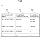
- Fig. 2 is a diagram showing a table configuration example of data stored in the in-vehicle terminal management unit 131.
- the in-vehicle terminal management unit 131 groups and manages a plurality of in-vehicle terminals 152 according to the installed vehicle model, year of release and type by using, for instance, the data of the table configuration illustrated in Fig. 2 .
- the data table of Fig. 2 is configured from the respective items of a manufacturer name 201, an in-vehicle terminal group 202, and an in-vehicle terminal ID 203.
- the manufacturer name 201 indicates the name of the manufacturer/seller of the vehicle in which the in-vehicle terminal 152 belonging to the respective in-vehicle terminal groups is installed.
- the in-vehicle terminal group 202 indicates the group name that is assigned to the respective in-vehicle terminal groups.
- the in-vehicle terminal ID 203 indicates the identifier for uniquely identifying the in-vehicle terminal 152 belonging to the respective in-vehicle terminal groups.
- the notification information management unit 132 stores data for managing notification information related to the items of the service provided from the processing server group 141 to the in-vehicle terminal 152 and the items of the service impact to be notified by the fault information providing server 101 at the time that a fault occurs in the processing server group 141. Based on the data stored in the notification information management unit 132, the service impact notification unit 121 can identify the items of the service impact to be notified to the user terminal 151 and the in-vehicle terminal 152 at the time a fault occurs in the processing server group 141.
- Fig. 3 is a diagram showing a table configuration example of data stored in the notification information management unit 132.
- the notification information management unit 132 manages, for each in-vehicle terminal group, the service provided from the processing server group 141 and the service impact to be notified at the time a fault occurs in the processing server group 141 by using, for instance, the data of the table configuration illustrated in Fig. 3 .
- the data table of Fig. 3 is configured from the respective items of an in-vehicle terminal group 301, a provided service 302, and a service impact 303.
- the in-vehicle terminal group 301 represents the group name that is assigned to the respective in-vehicle terminal groups, and corresponds to the in-vehicle terminal group 202 of the in-vehicle terminal management unit 131 shown in Fig. 2 .
- the provided service 302 represents the type of service that is being provided by the processing server group 141 to the respective in-vehicle terminal groups.
- the service impact 303 represents the items of the service impact to be provided by the fault information providing server 101 to the user terminal 151 and the in-vehicle terminal 152 at the time a fault occurs in the processing server group 141.
- the user terminal 151 corresponding to the in-vehicle terminal 152 of group 1 is the user terminal 151 of manufacturer A, and this can be identified based on the stored data of the in-vehicle terminal management unit 131 illustrated in Fig. 2 .
- group 2 is indicated in the column of in-vehicle terminal group 301
- service 2 is indicated in the column of provided service 302
- scheduled fault recovery time and "number of unusable terminals” are indicated in the column of service impact 303, respectively.
- the in-vehicle terminal 152 belonging to group 2 is receiving the service of service 2 from the processing server group 141, and, when a fault occurs in the processing server group 141, information regarding scheduled fault recovery time and number of unusable terminals is notified as the service impact to the in-vehicle terminal 152 of group 2 and the corresponding user terminal 151.
- the service configuration management unit 133 stores data for managing the service configuration of the processing server group 141. Based on the data stored in the service configuration management unit 133, the service impact calculation unit 122 can identify the server from which log information to be used in calculating the service impact at the time that a fault occurs in the processing server group 141 should be acquired.
- Fig. 4 is a diagram showing a table configuration example of data stored in the service configuration management unit 133.
- the service configuration management unit 133 manages, for each service, the respective servers configuring the processing server group 141 by using, for instance, the data of the table configuration illustrated in Fig. 4 .
- the data table of Fig. 4 is configured from the respective items of a service ID 401, a server type 402, and a server ID 403.
- the service ID 401 represents an identifier for uniquely identifying the service provided by each server of the processing server group 141, and corresponds to the provided service 302 of the notification information management unit 132 shown in Fig. 3 .
- the server type 402 represents the role of each server.
- the server ID 403 represents an identifier for uniquely identifying the server that is specifically implementing the role of each server.
- service 1 is indicated in the column of service ID 401
- Web server is indicated in the column of server type 402
- server 1 and “server 2” are indicated in the column of server ID 403, respectively.
- service 1 is indicated in the column of service ID 401
- AP server is indicated in the column of server type 402
- server 3 and “server 4" are indicated in the column of server ID 403, respectively
- service 1 is indicated in the column of service ID 401
- DB server is indicated in the column of server type 402
- server 5" and “server 6” are indicated in the column of server ID 403, respectively.
- This represents that service 1 is being provided by server 1 and server 2 as Web servers, server 3 and server 4 as AP (application) servers, and server 5 and server 6 as DB (database) servers.
- the calculation rule management unit 134 stores data for managing the calculation rules to be used in calculating the current impact on the service at the time that a fault occurs in the processing server group 141. Based on the data stored in the calculation rule management unit 134, the service impact calculation unit 122 can calculate the service impact at the time that a fault occurs in the processing server group 141.
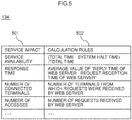
- Fig. 5 is a diagram showing a table configuration example of data stored in the calculation rule management unit 134.
- the calculation rule management unit 134 manages calculation rules which define the method of calculating the current service impact from the log information stored in the log management unit 137 by using, for instance, the data of the table configuration illustrated in Fig. 5 .
- the data table of Fig. 5 is configured from the respective items of a service impact 501, and calculation rules 502.
- the service impact 501 represents information to be provided by the fault information providing server 101 to the user terminal 151 and the in-vehicle terminal 152 at the time that a fault occurs, and corresponds to the service impact 303 of the notification information management unit 132 shown in Fig. 3 .
- the respective items of the service impact 501 do not overlap with the service impact (service impact 601 indicated in Fig. 6 described later) in the stored data of the estimation rule management unit 135.
- the service impact of the same item name should not be defined in both the calculation rule management unit 134 and the estimation rule management unit 135.
- the calculation rules 502 represent the specific calculation method of the respective items of the service impact 501.
- response time is indicated in the column of service impact 501
- average value of 'reply time of Web server - request reception time of Web server' is indicated in the column of calculation rules 502. This represents that the response time, which is one type of service impact, can be calculated as the average value of the time from the request reception time to the reply time of the Web server in the processing server group 141.
- the specific server ID of the Web server can be identified based on the stored information of the service configuration management unit 133 illustrated in Fig. 4 .
- the log information stored in the log management unit 137 includes information (e.g.: transaction ID or the like) capable of linking the reception of a request from each in-vehicle terminal 152 and the reply to the received request.
- the response time can be calculated by obtaining, based on the foregoing information, the average value of the time required from the reception to the reply of each request. Note that while the average value of the time from the request reception time to the reply time is used in the foregoing example, the maximum value or the minimum value may also be used.
- number of accesses is indicated in the column of service impact 501
- number of requests received by Web server is indicated in the column of calculation rules 502, respectively.
- the number of requests can be acquired from the log information stored in the log management unit 137. Note that, when there are a plurality of Web servers in the processing server group 141, the average value or total value of the number of requests of the respective Web servers may be calculated as the number of accesses.
- the number of accesses may be calculating by also deeming such retry as one request. Otherwise, the number of accesses may be calculated by omitting retries, or omitting retries during a given period.
- the calculation rule management unit 134 stores calculation rules for calculating the value of the respective items of the service impact. Note that the calculation rules depicted in Fig. 5 are merely an example, and various calculation rules may be set for each item of the service impact.
- the estimation rule management unit 135 stores data for managing the estimation rules to be used for estimating the current impact on the service at the time a fault occurs in the processing server group 141. Based on the data stored in the estimation rule management unit 135, the service impact calculation unit 122 can calculate the service impact at the time a fault occurs in the processing server group 141.
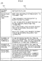
- Fig. 6 is a diagram showing a table configuration example of data stored in the estimation rule management unit 135.
- the estimation rule management unit 135 manages estimation rules which define the method of estimating the future service impact from the log information stored in the log management unit 137 and the log statistical information stored in the log statistical value management unit 136 by using, for instance, the data of the table configuration illustrated in Fig. 6 .
- the data table of Fig. 6 is configured from the respective items of a service impact 601, and estimation rules 602.
- the service impact 601 represents information to be provided by the fault information providing server 101 to the user terminal 151 and the in-vehicle terminal 152 at the time that a fault occurs, and corresponds to the service impact 303 of the notification information management unit 132 shown in Fig. 3 . Note that, as described above, preferably, the respective items of the service impact 601 do not overlap with the service impact 501 in the stored data of the calculation rule management unit 134 shown in Fig. 5 .
- the estimation rules 602 represent the specific estimation method of the respective items of the service impact 601.
- the time required for recovery is deemed to be 5 minutes.
- the time required for recovery is deemed to be 7 minutes
- the time required for recovery is deemed to be 8 minutes.
- the server reduction ratio is calculated by dividing the number of servers in operation by the number of servers used for the redundant configuration as indicated in the column of estimation rules 602.
- the reduction ratio of the Web server will be 0.5.
- the server reduction ratio of the processing server group 141 can be obtained.
- the estimation rule management unit 135 stores the estimation rules for estimating the value of the respective items of the service impact. Note that the estimation rules depicted in Fig. 6 are merely an example, and various estimation rules may be set for each item of the service impact.
- the log statistical value management unit 136 stores data for managing the log statistical information related to the statistical value of the log information of the processing server group 141 created by the log statistical processing unit 124. Based on the data stored in the log statistical value management unit 136, the service impact calculation unit 122 can calculate the service impact at the time that a fault occurs in the processing server group 141.
- Fig. 7 is a diagram showing a table configuration example of data stored in the log statistical value management unit 136.
- the log statistical value management unit 136 manages, for each service provided by the respective servers of the processing server group 141, the statistical value of the log information managed by the log management unit 137 by using, for instance, the data of the table configuration illustrated in Fig. 7 .
- the data table of Fig. 7 is configured from an item 701, a service ID 702, and a statistical value 703.
- the item 701 represents the contents of the respective statistical values.
- the service ID 702 represents an identifier for uniquely identifying the service provided by each server of the processing server group 141, and corresponds to the provided service 302 of the notification information management unit 132 shown in Fig. 3 , and the service ID 401 of the service configuration management unit 133 shown in Fig. 4 .
- the statistical value 703 represents the statistical values of each item.
- the log information stored in the log management unit 137 includes an in-vehicle terminal ID for identifying the in-vehicle terminal 152 connected to the Web server, and a service ID for identifying the service used by the in-vehicle terminal 152.
- the log information stored in the log management unit 137 includes an in-vehicle terminal ID for identifying the in-vehicle terminal 152 connected to the Web server, and a service ID for identifying the service used by the in-vehicle terminal 152.
- the maximum value or the minimum value may be used in substitute for the average value.
- the "hourly average number of accesses" and the "hourly average response time" indicated in the other lines can be calculated according to the same methods described above.
- the specific calculation method of the response time is the same as the method explained in Fig. 5 .
- the log management unit 137 stores data for managing the log information of the processing server group 141. Based on the data stored in the log management unit 137, the service impact calculation unit 122 can calculate the service impact at the time a fault occurs in the processing server group 141.
- the log management unit 137 collects log information from the processing server group 141 via the communication unit 115.
- the log information may also be notified by the processing server group 141 to the fault information providing server 101, or the log information may be acquired by the fault information providing server 101 requesting the log information to the processing server 141.
- the log information may be collected in real time, or collected periodically.
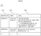
- Fig. 8 is a diagram showing a table configuration example of data stored in the log management unit 137.
- the log management unit 137 manages log information related to the history of the service provided by each server of the processing server group 141 by using, for instance, the data of the table configuration illustrated in Fig. 8 .
- the data table of Fig. 8 is configured from a server ID 801, a time 802, and a log 803.
- the server ID 801 represents an identifier for uniquely identifying the server in which each log occurred.
- the time 802 represents the time that each log occurred, and the log 803 represents the contents of the specific log information output from each server of the processing server group 141.
- the log information stored in the log 803 includes information such as a service ID for identifying the provided service, an in-vehicle terminal ID for identifying the in-vehicle terminal 152 to which the service was provided, and a transaction ID for identifying the transaction.
- a service ID for identifying the provided service
- an in-vehicle terminal ID for identifying the in-vehicle terminal 152 to which the service was provided
- a transaction ID for identifying the transaction.
- the foregoing data is stored in each management unit of the storage unit 111.
- the service impact notification unit 121 sends service impact information, which is used for notifying the impact on the service provided by that server, to the user terminal 151 and the in-vehicle terminal 152 via the communication unit 115.
- the service impact notification unit 121 receives information related to the service impact from the fault occurrence/recovery management unit 123.
- the information related to the service impact has the same data structure as the data stored in the notification information management unit 132 shown in Fig. 3 .
- the information related to the service impact is configured from a combination of "in-vehicle terminal group” which indicates the group of the target in-vehicle terminal 152, "service ID” which indicates the contents of the provided service that will be influenced by the fault, and "service impact” which indicates the impact on the provided service due to the fault.
- This service impact information means that the scheduled fault recovery time of service 1, which is being provided by each in-vehicle terminal 152 belonging to group 1, is 19:27.
- the service impact notification unit 121 may manage only the latest values of the information received from the fault occurrence/recovery management unit 123, or manage the history of the received information. In cases of managing the history, the history of only specific items of the service impact may be managed.
- the service impact notification unit 121 identifies the group of the in-vehicle terminal 152 based on the information received from the fault occurrence/recovery management unit 123, and notifies the service impact to the user terminal 151 corresponding to that group and the respective in-vehicle terminals 152.
- the manufacturer of the identified group of the in-vehicle terminal 152 is identified and the user terminal 151 of that manufacturer is set as the target of notification based on the information stored in the in-vehicle terminal management unit 131 based on the data structure shown in Fig. 2 .
- the line in which "manufacturer A” is indicated as the manufacturer name 201 of Fig. 2 is extracted with "manufacturer A” as the key, and "group 1" and "group 2" are identified based on the descriptions of the in-vehicle terminal group 202 in that line.
- information such as the time of fault occurrence and the list of in-vehicle terminals belonging to the in-vehicle terminal group is also notified.
- Fig. 9 is a diagram showing a flowchart of the processing to be executed by the service impact calculation unit 122 of the fault information providing server 101.
- the service impact calculation unit 122 identifies the service that is influenced by the fault.
- the service impact calculation unit 122 receives information related to the time of fault occurrence and the server of fault occurrence from the fault occurrence/recovery management unit 123.
- the service impact calculation unit 122 searches the service configuration management unit 133 with the server of fault occurrence represented by the received information as the key, and identifies the service ID of the service that is influenced by the fault.
- the service impact calculation unit 122 searches the line in which the ID number of the server of fault occurrence is included in the column of server ID 403 among the information stored in the service configuration management unit 133 based on the data structure shown in Fig. 4 , and identifies the service ID from the contents stored in the column of service ID 401 of that line. Note that since there are cases where a server is used for multiple services, even when there is only one server ID, there may be cases where multiple service IDs are searched.
- the service impact calculation unit 122 identifies the items of the service impact to be notified.
- the service impact calculation unit 122 searches the notification information management unit 132 with the service ID identified in step 901 as the key, and determines the items of the service impact.
- the service impact calculation unit 122 searches the line in which the service ID identified in step 901 is included in the column of provided service 302 among the information stored in the notification information management unit 132 based on the data structure shown in Fig. 3 , and identifies the items of the service impact from the contents stored in the column of service impact 303 of that line.
- the in-vehicle terminal group to be notified is also identified based on the contents described in the column of in-vehicle terminal group 301 of the same line.
- the service impact calculation unit 122 determines whether the items of the service impact identified in step 902 can be calculated based on the calculation rules managed by the calculation rule management unit 134.
- the service impact calculation unit 122 selects one among the combinations of the service ID identified in step 901, and the in-vehicle terminal group and the items of the service impact identified in step 902. Subsequently, the service impact calculation unit 122 searches the calculation rule management unit 134 with the items of the service impact of the selected combination as the key, and searches whether or not there is any corresponding service impact.
- the service impact calculation unit 122 searches the items of the service impact of the selected combination from the contents stored in the column of service impact 501 among the information stored in the calculation rule management unit 134 based on the data structure shown in Fig. 5 . Consequently, when there are items of the service impact in the service impact 501 (Yes), the service impact calculation unit 122 proceeds to step 904 upon determining that the items of the service impact can be calculated based on the calculation rules, and, when there are no items of the service impact in the service impact 501 (No), the service impact calculation unit 122 proceeds to step 905 upon determining that the items of the service impact cannot be calculated based on the calculation rules.
- the service impact calculation unit 122 proceeds to step 904 upon determining that the items of the service impact can be calculated based on the calculation rules.
- the service impact calculation unit 122 proceeds to step 905 upon determining that the items of the service impact cannot be calculated based on the calculation rules.
- the service impact calculation unit 122 calculates the service impact based on the log information and the calculation rules in step 904.
- the service impact calculation unit 122 acquires the calculation rules for calculating the item of the service impact based on the contents of the calculation rules 502 corresponding to the item of the service impact searched in step 903.
- the service impact calculation unit 122 collects log information required in the acquired calculation rules among the log information from the time of fault occurrence onward stored in the log management unit 137. Subsequently, the service impact calculation unit 122 uses the collected log information and performs the calculation according to the calculation rules, and thereby calculates the value of the service impact.
- the service impact calculation unit 122 foremost refers to the second line of the stored information table of the calculation rule management unit 134 shown in Fig. 5 and identifies that the calculation rules of the response time are "average value of 'reply time of Web server - request reception time of Web server'".
- the service impact calculation unit 122 acquires the log information 803 where the server ID 801 is "server 1" or “server 2" and the time 802 is "19:22 onward" from the stored information table of the log management unit 137 shown in Fig. 8 . Subsequently, the service impact calculation unit 122 calculates "average value of 'reply time of Web server - request reception time of Web server'" based on the calculation rules using the acquired log information.
- the service impact calculation unit 122 calculates the service impact based on the log information, the log statistical information and the estimation rules in step 905.
- the service impact calculation unit 122 searches the estimation rule management unit 135 with the item of the service impact identified in step 902 as the key, and acquires the estimation rules for calculating the item of the service impact.
- the service impact calculation unit 122 collects the log information and the log statistical information required in the acquired estimation rules among the log information and the log statistical information of the time of fault occurrence onward stored in the log management unit 137 and the log statistical value management unit 136, respectively.
- the service impact calculation unit 122 uses the collected log information and log statistical information and performs the calculation according to the estimation rules, and thereby calculates the value of the service impact.
- the service impact calculation unit 122 foremost refers to the first line of the stored information table of the estimation rule management unit 135 shown in Fig. 6 , and identifies the estimation rules of the scheduled fault recovery time.
- the service impact calculation unit 122 acquires the log information 803 where the server ID 801 is "server 1", “server 2", “server 3” or “server 4" and the time 802 is "19:32 onward" from the stored information table of the log management unit 137 shown in Fig. 8 .
- the range of the most recent log was set to 3 minutes, and log information of 19:32 onward, which is 3 minutes before the current time, was acquired. Subsequently, the service impact calculation unit 122 calculates the scheduled fault recovery time based on the estimation rules using the acquired log information. For example, when the time required for recovery is 5 minutes, by adding the 5 minutes as the time required for recovery to 19:35 as the current time, the scheduled fault recovery time is estimated to be 19:40.
- the service impact calculation unit 122 foremost refers to the second line of the stored information table of the estimation rule management unit 135 shown in Fig. 6 , and identifies the estimation rules of the number of unusable terminals.
- the service impact calculation unit 122 acquires the statistical value 703 where the item 701 is "hourly average number of connected terminals" and the service ID 702 is "service 1" from the stored information table of the log statistical value management unit 136 shown in Fig. 7 .
- step 906 the service impact calculation unit 122 confirms whether the service impact of all combinations has been calculated in relation to the service ID identified in step 901 and the item of the service impact identified in step 902.
- the service impact calculation unit 122 proceeds to step 907 when the service impact of all combinations has been calculated (Yes), and returns to step 903 when the service impact of all combinations has not been calculated (No).
- step 907 the service impact calculation unit 122 confirms whether the service impact of all groups has been calculated in relation to all in-vehicle terminal groups identified in step 902.
- the service impact calculation unit 122 ends the processing of Fig. 9 when the service impact of all groups has been calculated (Yes), and returns to step 903 when the service impact of all groups has not been calculated (No).
- the service impact calculation unit 122 can determine the items of the service impact to be calculated regarding the service that is influenced by the fault among the services provided by the processing server group 141. Furthermore, the service impact calculation unit 122 can calculate the service impact, for each in-vehicle terminal group that is influenced by the service provided by the processing server group 141 due to the occurrence of fault based on the calculation rules managed by the calculation rule management unit 134 or the estimation rules managed by the estimation rule management unit 135.
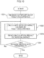
- Fig. 10 is a diagram showing a flowchart of the processing to be executed by the fault occurrence/recovery management unit 123 of the fault information providing server 101.
- the fault occurrence/recovery management unit 123 receives a notification of a fault occurrence from the processing server group 141.
- the fault occurrence notification information such as the fault ID, the time of fault occurrence, and the server of fault occurrence is received from the processing server group 141.
- the fault ID is an identifier for uniquely identifying the fault that occurred. It is also possible to monitor the resources of the processing server group 141 with an external server and automatically notify an alarm to the fault information providing server 101, or manually monitor the resources of the processing server group 141 and notify an alarm.
- the fault occurrence/recovery management unit 123 uses the service impact calculation unit 122 to calculate the service impact caused by the occurrence of a fault.
- the fault occurrence/recovery management unit 123 requests the service impact calculation unit 122 to calculate the service impact by using, as the parameters, the time of fault occurrence and the server of fault occurrence in the fault occurrence notification received in step 1001.
- the service impact calculation unit 122 executes the processing explained with reference to the flowchart of Fig. 9 , and thereafter replies the calculation result of the service impact to the fault occurrence/recovery management unit 123.
- the calculation result of the service impact sent from the service impact calculation unit 122 to the fault occurrence/recovery management unit 123 is configured from information such as the in-vehicle terminal group, the service ID, and the service impact.
- step 1003 the fault occurrence/recovery management unit 123 sends the calculation result of the service impact acquired in step 1002 to the service impact notification unit 121.
- step 1004 the fault occurrence/recovery management unit 123 determines whether the fault received in step 1001 has been recovered.
- the fault occurrence/recovery management unit 123 ends the processing of Fig. 10 when the service has recovered from the fault (Yes), and returns to step 1002 when the service has not recovered from the fault (No). This determination may be made, for example, by receiving the notification of the fault ID and the fault recovery time of the recovered service in the same manner as step 1001.
- the fault occurrence/recovery management unit 123 upon receiving the notification of fault occurrence from the processing server group 141 in step 1001, preferably, the fault occurrence/recovery management unit 123 periodically performs the processing of steps 1002 to 1004.
- the service impact calculation unit 122 can re-calculate the latest value of the service impact for each predetermined cycle during the period from the time that a fault occurs in the processing server group 141 to the time that the service recovers from the fault.
- the service impact notification unit 121 can notify the latest value of the service impact for each predetermined cycle obtained by the service impact calculation unit 122 to the service user.
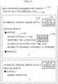
- Fig. 11 is a diagram showing a notification screen example to be displayed on the user terminal 151.
- the screen shown in Fig. 11 displays a manufacturer name 1101, a time of fault occurrence 1102, and information of the service impact of the respective in-vehicle terminal groups belonging to manufacturer A.
- Information of the service impact for each in-vehicle terminal group includes an in-vehicle terminal group 1103, an in-vehicle terminal list button 1104, a per-service service impact 1105, and a history button 1106.
- a list of the in-vehicle terminals 152 belonging to the group (group 1 in this example) of the in-vehicle terminals 152 indicated by the in-vehicle terminal group 1103 corresponding to the in-vehicle terminal list button 1104 is displayed as a pop-up screen.
- the history button 1106 is pressed, the history information of the service impact corresponding to the history button 1106 is displayed as a graph. For example, when the history button 1106 on the right side of the service availability is pressed, a history graph of the service availability is displayed as a pop-up screen.
- Fig. 12 is a diagram showing a notification screen example to be displayed on the in-vehicle terminal 152. On the screen shown in Fig. 12 , a time of fault occurrence 1201 and a per-service service impact 1202 are displayed.
Landscapes
- Engineering & Computer Science (AREA)
- Theoretical Computer Science (AREA)
- General Engineering & Computer Science (AREA)
- Physics & Mathematics (AREA)
- General Physics & Mathematics (AREA)
- Quality & Reliability (AREA)
- Computer Hardware Design (AREA)
- Business, Economics & Management (AREA)
- Biomedical Technology (AREA)
- Health & Medical Sciences (AREA)
- Strategic Management (AREA)
- Life Sciences & Earth Sciences (AREA)
- Finance (AREA)
- General Business, Economics & Management (AREA)
- Economics (AREA)
- Development Economics (AREA)
- Accounting & Taxation (AREA)
- Marketing (AREA)
- Bioinformatics & Cheminformatics (AREA)
- Bioinformatics & Computational Biology (AREA)
- Evolutionary Biology (AREA)
- Probability & Statistics with Applications (AREA)
- Debugging And Monitoring (AREA)
- Management, Administration, Business Operations System, And Electronic Commerce (AREA)
Claims (13)
- Fehlerinformationsbereitstellungsserver (101), der mit einer Verarbeitungsservergruppe (141) verbunden ist, die aus einer Vielzahl von Servern konfiguriert ist, und der einem Benutzer eines von der Verarbeitungsservergruppe bereitgestellten Diensts Informationen in Bezug auf einen Fehler bereitstellt, der in der Verarbeitungsservergruppe aufgetreten ist, Folgendes umfassend:eine Fehlerauftritts-/Wiederherstellungsverwaltungseinheit (123), die das Auftreten von Fehlern der Verarbeitungsservergruppe verwaltet;eine Protokollverwaltungseinheit (137), die Protokollinformationen in Bezug auf eine Historie der von jedem Server der Verarbeitungsservergruppe bereitgestellten Dienste verwaltet;eine Regelverwaltungseinheit, die Regeln in Bezug auf eine Dienstauswirkung verwaltet, die eine durch den Fehler verursachte Auswirkung auf den Dienst darstellt;eine Dienstauswirkungsberechnungseinheit (122), die die Dienstauswirkung basierend auf den Protokollinformationen und den Regeln berechnet; undeine Dienstauswirkungsmitteilungseinheit (121), die dem Benutzer den durch die Dienstauswirkungsberechnungseinheit berechnete Dienstauswirkung mitteilt, undeine Im-Fahrzeug-Endgerätverwaltungseinheit (131), die eine Vielzahl von Im-Fahrzeug-Endgeräten in Gruppeneinheiten verwaltet, wobei jedes der Im-Fahrzeug-Endgeräte vom Benutzer gehalten wird und den Dienst empfängt,wobei die Dienstauswirkungsberechnungseinheit die Dienstauswirkung für jede Gruppe der Im-Fahrzeug-Endgeräte berechnet.
- Fehlerinformationsbereitstellungsserver nach Anspruch 1,
wobei die Regelverwaltungseinheit eine Berechnungsregelverwaltungseinheit (134) umfasst, die Berechnungsregeln zur Berechnung einer aktuellen durch den Fehler verursachten Auswirkung auf den Dienst verwaltet, und wobei
die Dienstauswirkungsberechnungseinheit die Dienstauswirkung basierend auf den Protokollinformationen und den Berechnungsregeln berechnet. - Fehlerinformationsbereitstellungsserver nach Anspruch 1 oder 2, ferner Folgendes umfassend:eine Protokollstatistikwertverwaltungseinheit (136), die Protokollstatistikinformationen in Bezug auf einen statistischen Wert der Protokollinformationen verwaltet,wobei die Regelverwaltungseinheit eine Schätzungsregelverwaltungseinheit (135) umfasst, die Schätzungsregeln zur Schätzung einer künftigen durch den Fehler verursachten Auswirkung auf den Dienst verwaltet, und wobeidie Dienstauswirkungsberechnungseinheit die Dienstauswirkung basierend auf den Protokollinformationen, den Protokollstatistikinformationen und den Schätzungsregeln berechnet.
- Fehlerinformationsbereitstellungsserver nach Anspruch 3,
wobei die Schätzungsregelverwaltungseinheit Schätzungsregeln verwaltet, die zumindest eines aus Folgenden umfasst: Schätzungsregeln zur Schätzung einer geplanten Wiederherstellungszeit nach dem Fehler, Schätzungsregeln zur Schätzung einer Anzahl an Benutzern, deren Dienstbenutzung aufgrund des Fehlers eingeschränkt sein wird, Schätzungsregeln zur Schätzung einer Anzahl an Zugriffen der Benutzer, deren Verbindung mit der Verarbeitungsservergruppe aufgrund des Fehlers fehlerhaft sein wird, und Schätzungsregeln zur Schätzung einer Reaktionsverzögerungsrate der Verarbeitungsservergruppe aufgrund des Fehlers. - Fehlerinformationsbereitstellungsserver nach Anspruch 1, ferner Folgendes umfassend:eine Mitteilungsinformationsverwaltungseinheit (132), die Mitteilungsinformationen in Bezug auf einen Mitteilungsgegenstand des Satzes von Dienstauswirkungen für jede Gruppe der Im-Fahrzeug-Endgeräte verwaltet,wobei die Dienstauswirkungsmitteilungseinheit dem Benutzer die Dienstauswirkung, die für jede Gruppe von Im-Fahrzeug-Endgeräten unterschiedlich ist, basierend auf den Mitteilungsinformationen mitteilt.
- Fehlerinformationsbereitstellungsserver nach einem der Ansprüche 1 bis 5,
wobei die Dienstauswirkungsberechnungseinheit einen jüngsten Wert der Dienstauswirkung für jeden vorbestimmten Zyklus erneut berechnet und wobei
die Dienstauswirkungsmitteilungseinheit dem Benutzer den jüngsten Wert der Dienstauswirkung, der von der Dienstauswirkungsberechnungseinheit erhalten wurde, für jeden der vorbestimmten Zyklen mitteilt. - Fehlerinformationsbereitstellungsserver nach einem der Ansprüche 1 bis 6, wobei die Dienstauswirkungsmitteilungseinheit dem Benutzer die Dienstauswirkung mitteilt, indem sie Informationen, die auf einem Bildschirm anzuzeigen sind und zumindest einen Zeitpunkt des Auftretens des Fehlers umfassen, sowie die Dienstauswirkung für jeden der Dienste gemäß Attributen des Benutzers sendet.
- Fehlerinformationsbereitstellungsverfahren, das einen Fehlerinformationsbereitstellungsserver (101) verwendet, der mit einer Verarbeitungsservergruppe (141) verbunden ist, die aus einer Vielzahl von Servern konfiguriert ist, und der einem Benutzer eines von der Verarbeitungsservergruppe bereitgestellten Diensts Informationen in Bezug auf einen Fehler bereitstellt, der in der Verarbeitungsservergruppe aufgetreten ist, wobei der Fehlerinformationsbereitstellungsserver:das Auftreten von Fehlern der Verarbeitungsservergruppe verwaltet;Protokollinformationen in Bezug auf eine Historie der von jedem Server der Verarbeitungsservergruppe bereitgestellten Dienste verwaltet;Regeln in Bezug auf eine Dienstauswirkung verwaltet, die eine durch den Fehler verursachte Auswirkung auf den Dienst darstellt;die Dienstauswirkung basierend auf den Protokollinformationen und den Regeln berechnet; unddem Benutzer die Dienstauswirkung mitteilt,wobei der Fehlerinformationsbereitstellungsserver ferner eine Vielzahl von Im-Fahrzeug-Endgeräten in Gruppeneinheiten verwaltet, wobei jedes der Im-Fahrzeug-Endgeräte vom Benutzer gehalten wird und den Dienst empfängt,wobei beim Berechnen der Dienstauswirkung die Dienstauswirkung für jede Gruppe der Im-Fahrzeug-Endgeräte berechnet wird.
- Fehlerinformationsbereitstellungsverfahren nach Anspruch 8,
wobei beim Verwalten der Regeln Berechnungsregeln zur Berechnung einer aktuellen durch den Fehler verursachten Auswirkung auf den Dienst verwaltet werden und wobei
beim Berechnen der Dienstauswirkung die Dienstauswirkung basierend auf den Protokollinformationen und den Berechnungsregeln berechnet wird. - Fehlerinformationsbereitstellungsverfahren nach Anspruch 8 oder 9,
wobei der Fehlerinformationsbereitstellungsserver weiter Protokollstatistikinformationen in Bezug auf einen statistischen Wert der Protokollinformationen verwaltet, wobei
beim Verwalten der Regeln Schätzungsregeln zur Schätzung einer zukünftigen durch den Fehler verursachten Auswirkung auf den Dienst verwaltet werden und wobei
beim Berechnen der Dienstauswirkung die Dienstauswirkung basierend auf den Protokollinformationen, den Protokollstatistikinformationen und den Schätzungsregeln berechnet wird. - Fehlerinformationsbereitstellungsverfahren nach Anspruch 10,
wobei beim Verwalten der Schätzungsregeln Schätzungsregeln verwaltet werden, die zumindest eines aus Folgenden umfasst: Schätzungsregeln zur Schätzung einer geplanten Wiederherstellungszeit nach dem Fehler, Schätzungsregeln zur Schätzung einer Anzahl an Benutzern, deren Dienstbenutzung aufgrund des Fehlers eingeschränkt sein wird, Schätzungsregeln zur Schätzung einer Anzahl an Zugriffen der Benutzer, deren Verbindung mit der Verarbeitungsservergruppe aufgrund des Fehlers fehlerhaft sein wird, und Schätzungsregeln zur Schätzung einer Reaktionsverzögerungsrate der Verarbeitungsservergruppe aufgrund des Fehlers. - Fehlerinformationsbereitstellungsverfahren nach Anspruch 8,
wobei der Fehlerinformationsbereitstellungsserver ferner Mitteilungsinformationen in Bezug auf einen Mitteilungsgegenstand des Satzes von Dienstauswirkungen für jede Gruppe der Im-Fahrzeug-Endgeräte verwaltet,
wobei beim Mitteilen der Dienstauswirkung dem Benutzer die Dienstauswirkung, die für jede Gruppe von Im-Fahrzeug-Endgeräten unterschiedlich ist, basierend auf den Mitteilungsinformationen mitgeteilt wird. - Fehlerinformationsbereitstellungsverfahren nach einem der Ansprüche 8 bis 12,
wobei beim Berechnen der Dienstauswirkung ein jüngster Wert der Dienstauswirkung für jeden vorbestimmten Zyklus erneut berechnet wird und wobei
beim Berechnen der Dienstauswirkung dem Benutzer der jüngste Wert der Dienstauswirkung, der von der Dienstauswirkungsberechnungseinheit erhalten wurde, für jeden der vorbestimmten Zyklen mitgeteilt wird.
Applications Claiming Priority (2)
| Application Number | Priority Date | Filing Date | Title |
|---|---|---|---|
| JP2014262091A JP6306499B2 (ja) | 2014-12-25 | 2014-12-25 | 障害情報提供サーバ、障害情報提供方法 |
| PCT/JP2015/083077 WO2016104025A1 (ja) | 2014-12-25 | 2015-11-25 | 障害情報提供サーバ、障害情報提供方法 |
Publications (3)
| Publication Number | Publication Date |
|---|---|
| EP3239840A1 EP3239840A1 (de) | 2017-11-01 |
| EP3239840A4 EP3239840A4 (de) | 2018-08-29 |
| EP3239840B1 true EP3239840B1 (de) | 2019-09-11 |
Family
ID=56150057
Family Applications (1)
| Application Number | Title | Priority Date | Filing Date |
|---|---|---|---|
| EP15872594.5A Not-in-force EP3239840B1 (de) | 2014-12-25 | 2015-11-25 | Fehlerinformationsbereitstellungsserver und fehlerinformationbereitstellungsverfahren |
Country Status (5)
| Country | Link |
|---|---|
| US (1) | US10437695B2 (de) |
| EP (1) | EP3239840B1 (de) |
| JP (1) | JP6306499B2 (de) |
| CN (1) | CN107003926B (de) |
| WO (1) | WO2016104025A1 (de) |
Families Citing this family (11)
| Publication number | Priority date | Publication date | Assignee | Title |
|---|---|---|---|---|
| JP6913206B2 (ja) * | 2016-08-25 | 2021-08-04 | フォルシアクラリオン・エレクトロニクス株式会社 | ログ解析方法及びログ優先度テーブル管理方法 |
| US10367682B2 (en) * | 2017-06-30 | 2019-07-30 | Bank Of American Corporation | Node failure recovery tool |
| US10565021B2 (en) * | 2017-11-30 | 2020-02-18 | Microsoft Technology Licensing, Llc | Automated capacity management in distributed computing systems |
| CN108959051A (zh) * | 2018-06-29 | 2018-12-07 | 深圳市同泰怡信息技术有限公司 | 服务器系统日志收集方法 |
| CN109639490B (zh) * | 2018-12-18 | 2020-09-18 | 网宿科技股份有限公司 | 一种宕机通知方法及装置 |
| JP7436146B2 (ja) * | 2019-02-07 | 2024-02-21 | 日本電信電話株式会社 | 障害情報周知装置及び障害情報周知方法 |
| JP7134903B2 (ja) * | 2019-03-05 | 2022-09-12 | 株式会社日立製作所 | 不具合再現支援システム、不具合再現支援方法 |
| JP7298343B2 (ja) * | 2019-07-01 | 2023-06-27 | 日本電信電話株式会社 | 故障影響推定装置、故障影響推定方法、及びプログラム |
| US20240012406A1 (en) * | 2021-01-27 | 2024-01-11 | Mitsubishi Electric Corporation | Failure indication notification system |
| US12585516B2 (en) | 2021-10-20 | 2026-03-24 | Telefonaktiebolaget Lm Ericsson (Publ) | Method and apparatus for vehicle application |
| US20250219893A1 (en) * | 2023-12-27 | 2025-07-03 | Servicenow, Inc. | Root Cause and Impact Determination Based on Automated Service Identification |
Family Cites Families (21)
| Publication number | Priority date | Publication date | Assignee | Title |
|---|---|---|---|---|
| JP3642004B2 (ja) * | 2000-05-22 | 2005-04-27 | 日本電気株式会社 | 中継装置、移動体無線通信システム、その障害通知方法、及びその障害通知プログラムを記録した記録媒体 |
| JP3654151B2 (ja) * | 2000-07-17 | 2005-06-02 | 日本電気株式会社 | 携帯端末を利用した保守情報通知方法及びシステム並びに記録媒体 |
| JP2002108728A (ja) * | 2000-10-02 | 2002-04-12 | Ntt Docomo Inc | 障害情報の掲載方法およびプロバイダ設備 |
| JP3917877B2 (ja) * | 2002-02-28 | 2007-05-23 | 株式会社エヌ・ティ・ティ・ドコモ | サービス管理装置及びサービス管理装置における異常情報出力方法 |
| US20040163007A1 (en) * | 2003-02-19 | 2004-08-19 | Kazem Mirkhani | Determining a quantity of lost units resulting from a downtime of a software application or other computer-implemented system |
| JP4485763B2 (ja) * | 2003-07-10 | 2010-06-23 | 株式会社日立製作所 | 運用管理方法及び装置 |
| US20060072707A1 (en) * | 2004-09-30 | 2006-04-06 | International Business Machines Corporation | Method and apparatus for determining impact of faults on network service |
| US7739244B2 (en) * | 2004-10-14 | 2010-06-15 | Oracle International Corporation | Operating logging for online recovery in shared memory information systems |
| US20060112317A1 (en) * | 2004-11-05 | 2006-05-25 | Claudio Bartolini | Method and system for managing information technology systems |
| US8181071B2 (en) * | 2007-06-29 | 2012-05-15 | Microsoft Corporation | Automatically managing system downtime in a computer network |
| JP4867908B2 (ja) * | 2007-12-19 | 2012-02-01 | 日本電気株式会社 | 監視システム、ネットワーク監視装置及びサービス実行環境監視方法 |
| US7793141B1 (en) * | 2008-05-15 | 2010-09-07 | Bank Of America Corporation | eCommerce outage customer notification |
| US20100157964A1 (en) * | 2008-12-18 | 2010-06-24 | Pantech & Curitel Communications, Inc. | Server to guide reconnection in mobile internet, method for guiding server reconnection, and server reconnection method |
| CN102143008A (zh) * | 2010-01-29 | 2011-08-03 | 国际商业机器公司 | 用于数据中心的诊断故障事件的方法及装置 |
| US8887006B2 (en) * | 2011-04-04 | 2014-11-11 | Microsoft Corporation | Proactive failure handling in database services |
| JP5370624B2 (ja) * | 2011-09-08 | 2013-12-18 | 日本電気株式会社 | クラウドサービス復旧時間予測システム、方法およびプログラム |
| US9152487B2 (en) * | 2011-09-30 | 2015-10-06 | Microsoft Technology Licensing, Llc | Service outage details in an error message |
| US8837302B2 (en) * | 2012-04-27 | 2014-09-16 | Motorola Mobility Llc | Mapping a network fault |
| US20160013990A1 (en) * | 2014-07-09 | 2016-01-14 | Cisco Technology, Inc. | Network traffic management using heat maps with actual and planned /estimated metrics |
| US20160072688A1 (en) * | 2014-09-08 | 2016-03-10 | Mayank DESAI | Fault monitoring in multi-domain networks |
| US9639411B2 (en) * | 2015-07-24 | 2017-05-02 | Bank Of America Corporation | Impact notification system |
-
2014
- 2014-12-25 JP JP2014262091A patent/JP6306499B2/ja not_active Expired - Fee Related
-
2015
- 2015-11-25 US US15/531,743 patent/US10437695B2/en active Active
- 2015-11-25 EP EP15872594.5A patent/EP3239840B1/de not_active Not-in-force
- 2015-11-25 WO PCT/JP2015/083077 patent/WO2016104025A1/ja not_active Ceased
- 2015-11-25 CN CN201580055503.1A patent/CN107003926B/zh not_active Expired - Fee Related
Non-Patent Citations (1)
| Title |
|---|
| None * |
Also Published As
| Publication number | Publication date |
|---|---|
| CN107003926A (zh) | 2017-08-01 |
| JP6306499B2 (ja) | 2018-04-04 |
| JP2016122337A (ja) | 2016-07-07 |
| WO2016104025A1 (ja) | 2016-06-30 |
| EP3239840A1 (de) | 2017-11-01 |
| US10437695B2 (en) | 2019-10-08 |
| US20170269986A1 (en) | 2017-09-21 |
| EP3239840A4 (de) | 2018-08-29 |
| CN107003926B (zh) | 2020-04-28 |
Similar Documents
| Publication | Publication Date | Title |
|---|---|---|
| US10437695B2 (en) | Fault information providing server and fault information providing method for users of in-vehicle terminals | |
| EP4348429B1 (de) | Erkennung eines datencentermassenausfalls mit nahechtzeit-/offlinedaten unter verwendung von ml-modellen | |
| US9246777B2 (en) | Computer program and monitoring apparatus | |
| EP2523115B1 (de) | Operationsverwaltungsvorrichtung, operationsverwaltungsverfahren und programmspeichermedium | |
| US20160378583A1 (en) | Management computer and method for evaluating performance threshold value | |
| CN110275992B (zh) | 应急处理方法、装置、服务器及计算机可读存储介质 | |
| JPWO2013140608A1 (ja) | イベントの根本原因の解析を支援する方法及びシステム | |
| US8914798B2 (en) | Production control for service level agreements | |
| US9461879B2 (en) | Apparatus and method for system error monitoring | |
| EP4732148A1 (de) | Nutzung von gesundheitszuständen von abhängigkeitsinstanzen zur analyse der ausfallursache | |
| US9317355B2 (en) | Dynamically determining an external systems management application to report system errors | |
| CN110875832A (zh) | 异常业务监控方法、装置、系统及计算机可读存储介质 | |
| CN109962914B (zh) | 一种防火墙配置方法及装置 | |
| CN111835566A (zh) | 一种系统故障管理方法、装置及系统 | |
| JP4867908B2 (ja) | 監視システム、ネットワーク監視装置及びサービス実行環境監視方法 | |
| JP6015750B2 (ja) | ログ収集サーバ、ログ収集システム、ログ収集方法 | |
| US9372746B2 (en) | Methods for identifying silent failures in an application and devices thereof | |
| JP2011028490A (ja) | システム監視装置、システム監視方法、及びプログラム | |
| CN108874621A (zh) | 文件监控方法、装置、电子设备及计算机可读存储介质 | |
| CN112799957A (zh) | 基于用户行为的故障处理方法、系统、设备和介质 | |
| KR101675098B1 (ko) | 서버를 관리하는 장치 및 방법 | |
| JP2020068408A (ja) | 影響範囲通知装置、影響範囲通知システム、影響範囲通知方法、及びプログラム | |
| CN121396837A (zh) | 云平台的运行检测方法、装置、设备及介质 | |
| US10282775B1 (en) | System, method, and computer program for automatically remediating fallouts in an ordering system of a consumer telecommunications network | |
| CN113282414A (zh) | 业务处理方法、装置、计算机设备及存储介质 |
Legal Events
| Date | Code | Title | Description |
|---|---|---|---|
| STAA | Information on the status of an ep patent application or granted ep patent |
Free format text: STATUS: THE INTERNATIONAL PUBLICATION HAS BEEN MADE |
|
| PUAI | Public reference made under article 153(3) epc to a published international application that has entered the european phase |
Free format text: ORIGINAL CODE: 0009012 |
|
| STAA | Information on the status of an ep patent application or granted ep patent |
Free format text: STATUS: REQUEST FOR EXAMINATION WAS MADE |
|
| 17P | Request for examination filed |
Effective date: 20170517 |
|
| AK | Designated contracting states |
Kind code of ref document: A1 Designated state(s): AL AT BE BG CH CY CZ DE DK EE ES FI FR GB GR HR HU IE IS IT LI LT LU LV MC MK MT NL NO PL PT RO RS SE SI SK SM TR |
|
| AX | Request for extension of the european patent |
Extension state: BA ME |
|
| DAV | Request for validation of the european patent (deleted) | ||
| DAX | Request for extension of the european patent (deleted) | ||
| A4 | Supplementary search report drawn up and despatched |
Effective date: 20180730 |
|
| RIC1 | Information provided on ipc code assigned before grant |
Ipc: G06Q 50/10 20120101ALI20180724BHEP Ipc: G06F 11/07 20060101ALI20180724BHEP Ipc: G06F 11/34 20060101AFI20180724BHEP |
|
| GRAP | Despatch of communication of intention to grant a patent |
Free format text: ORIGINAL CODE: EPIDOSNIGR1 |
|
| STAA | Information on the status of an ep patent application or granted ep patent |
Free format text: STATUS: GRANT OF PATENT IS INTENDED |
|
| INTG | Intention to grant announced |
Effective date: 20190405 |
|
| RIN1 | Information on inventor provided before grant (corrected) |
Inventor name: TSURUSU, KYOUSUKE Inventor name: SOBUE, TSUNEO Inventor name: NAGAI, YASUSHI Inventor name: OSAFUNE, TATSUAKI Inventor name: ENDOU, HIROYOSHI |
|
| GRAS | Grant fee paid |
Free format text: ORIGINAL CODE: EPIDOSNIGR3 |
|
| GRAA | (expected) grant |
Free format text: ORIGINAL CODE: 0009210 |
|
| STAA | Information on the status of an ep patent application or granted ep patent |
Free format text: STATUS: THE PATENT HAS BEEN GRANTED |
|
| AK | Designated contracting states |
Kind code of ref document: B1 Designated state(s): AL AT BE BG CH CY CZ DE DK EE ES FI FR GB GR HR HU IE IS IT LI LT LU LV MC MK MT NL NO PL PT RO RS SE SI SK SM TR |
|
| REG | Reference to a national code |
Ref country code: GB Ref legal event code: FG4D |
|
| REG | Reference to a national code |
Ref country code: CH Ref legal event code: EP |
|
| REG | Reference to a national code |
Ref country code: AT Ref legal event code: REF Ref document number: 1179363 Country of ref document: AT Kind code of ref document: T Effective date: 20190915 |
|
| REG | Reference to a national code |
Ref country code: DE Ref legal event code: R096 Ref document number: 602015038022 Country of ref document: DE Ref country code: IE Ref legal event code: FG4D |
|
| REG | Reference to a national code |
Ref country code: NL Ref legal event code: MP Effective date: 20190911 |
|
| REG | Reference to a national code |
Ref country code: LT Ref legal event code: MG4D |
|
| PG25 | Lapsed in a contracting state [announced via postgrant information from national office to epo] |
Ref country code: NO Free format text: LAPSE BECAUSE OF FAILURE TO SUBMIT A TRANSLATION OF THE DESCRIPTION OR TO PAY THE FEE WITHIN THE PRESCRIBED TIME-LIMIT Effective date: 20191211 Ref country code: LT Free format text: LAPSE BECAUSE OF FAILURE TO SUBMIT A TRANSLATION OF THE DESCRIPTION OR TO PAY THE FEE WITHIN THE PRESCRIBED TIME-LIMIT Effective date: 20190911 Ref country code: BG Free format text: LAPSE BECAUSE OF FAILURE TO SUBMIT A TRANSLATION OF THE DESCRIPTION OR TO PAY THE FEE WITHIN THE PRESCRIBED TIME-LIMIT Effective date: 20191211 Ref country code: FI Free format text: LAPSE BECAUSE OF FAILURE TO SUBMIT A TRANSLATION OF THE DESCRIPTION OR TO PAY THE FEE WITHIN THE PRESCRIBED TIME-LIMIT Effective date: 20190911 Ref country code: HR Free format text: LAPSE BECAUSE OF FAILURE TO SUBMIT A TRANSLATION OF THE DESCRIPTION OR TO PAY THE FEE WITHIN THE PRESCRIBED TIME-LIMIT Effective date: 20190911 Ref country code: SE Free format text: LAPSE BECAUSE OF FAILURE TO SUBMIT A TRANSLATION OF THE DESCRIPTION OR TO PAY THE FEE WITHIN THE PRESCRIBED TIME-LIMIT Effective date: 20190911 |
|
| PG25 | Lapsed in a contracting state [announced via postgrant information from national office to epo] |
Ref country code: AL Free format text: LAPSE BECAUSE OF FAILURE TO SUBMIT A TRANSLATION OF THE DESCRIPTION OR TO PAY THE FEE WITHIN THE PRESCRIBED TIME-LIMIT Effective date: 20190911 Ref country code: ES Free format text: LAPSE BECAUSE OF FAILURE TO SUBMIT A TRANSLATION OF THE DESCRIPTION OR TO PAY THE FEE WITHIN THE PRESCRIBED TIME-LIMIT Effective date: 20190911 Ref country code: GR Free format text: LAPSE BECAUSE OF FAILURE TO SUBMIT A TRANSLATION OF THE DESCRIPTION OR TO PAY THE FEE WITHIN THE PRESCRIBED TIME-LIMIT Effective date: 20191212 Ref country code: RS Free format text: LAPSE BECAUSE OF FAILURE TO SUBMIT A TRANSLATION OF THE DESCRIPTION OR TO PAY THE FEE WITHIN THE PRESCRIBED TIME-LIMIT Effective date: 20190911 Ref country code: LV Free format text: LAPSE BECAUSE OF FAILURE TO SUBMIT A TRANSLATION OF THE DESCRIPTION OR TO PAY THE FEE WITHIN THE PRESCRIBED TIME-LIMIT Effective date: 20190911 |
|
| REG | Reference to a national code |
Ref country code: AT Ref legal event code: MK05 Ref document number: 1179363 Country of ref document: AT Kind code of ref document: T Effective date: 20190911 |
|
| PG25 | Lapsed in a contracting state [announced via postgrant information from national office to epo] |
Ref country code: PT Free format text: LAPSE BECAUSE OF FAILURE TO SUBMIT A TRANSLATION OF THE DESCRIPTION OR TO PAY THE FEE WITHIN THE PRESCRIBED TIME-LIMIT Effective date: 20200113 Ref country code: IT Free format text: LAPSE BECAUSE OF FAILURE TO SUBMIT A TRANSLATION OF THE DESCRIPTION OR TO PAY THE FEE WITHIN THE PRESCRIBED TIME-LIMIT Effective date: 20190911 Ref country code: AT Free format text: LAPSE BECAUSE OF FAILURE TO SUBMIT A TRANSLATION OF THE DESCRIPTION OR TO PAY THE FEE WITHIN THE PRESCRIBED TIME-LIMIT Effective date: 20190911 Ref country code: EE Free format text: LAPSE BECAUSE OF FAILURE TO SUBMIT A TRANSLATION OF THE DESCRIPTION OR TO PAY THE FEE WITHIN THE PRESCRIBED TIME-LIMIT Effective date: 20190911 Ref country code: PL Free format text: LAPSE BECAUSE OF FAILURE TO SUBMIT A TRANSLATION OF THE DESCRIPTION OR TO PAY THE FEE WITHIN THE PRESCRIBED TIME-LIMIT Effective date: 20190911 Ref country code: RO Free format text: LAPSE BECAUSE OF FAILURE TO SUBMIT A TRANSLATION OF THE DESCRIPTION OR TO PAY THE FEE WITHIN THE PRESCRIBED TIME-LIMIT Effective date: 20190911 Ref country code: NL Free format text: LAPSE BECAUSE OF FAILURE TO SUBMIT A TRANSLATION OF THE DESCRIPTION OR TO PAY THE FEE WITHIN THE PRESCRIBED TIME-LIMIT Effective date: 20190911 |
|
| PG25 | Lapsed in a contracting state [announced via postgrant information from national office to epo] |
Ref country code: IS Free format text: LAPSE BECAUSE OF FAILURE TO SUBMIT A TRANSLATION OF THE DESCRIPTION OR TO PAY THE FEE WITHIN THE PRESCRIBED TIME-LIMIT Effective date: 20200224 Ref country code: SK Free format text: LAPSE BECAUSE OF FAILURE TO SUBMIT A TRANSLATION OF THE DESCRIPTION OR TO PAY THE FEE WITHIN THE PRESCRIBED TIME-LIMIT Effective date: 20190911 Ref country code: CZ Free format text: LAPSE BECAUSE OF FAILURE TO SUBMIT A TRANSLATION OF THE DESCRIPTION OR TO PAY THE FEE WITHIN THE PRESCRIBED TIME-LIMIT Effective date: 20190911 Ref country code: SM Free format text: LAPSE BECAUSE OF FAILURE TO SUBMIT A TRANSLATION OF THE DESCRIPTION OR TO PAY THE FEE WITHIN THE PRESCRIBED TIME-LIMIT Effective date: 20190911 |
|
| REG | Reference to a national code |
Ref country code: DE Ref legal event code: R097 Ref document number: 602015038022 Country of ref document: DE |
|
| REG | Reference to a national code |
Ref country code: CH Ref legal event code: PL |
|
| PLBE | No opposition filed within time limit |
Free format text: ORIGINAL CODE: 0009261 |
|
| STAA | Information on the status of an ep patent application or granted ep patent |
Free format text: STATUS: NO OPPOSITION FILED WITHIN TIME LIMIT |
|
| PG2D | Information on lapse in contracting state deleted |
Ref country code: IS |
|
| PG25 | Lapsed in a contracting state [announced via postgrant information from national office to epo] |
Ref country code: CH Free format text: LAPSE BECAUSE OF NON-PAYMENT OF DUE FEES Effective date: 20191130 Ref country code: LU Free format text: LAPSE BECAUSE OF NON-PAYMENT OF DUE FEES Effective date: 20191125 Ref country code: MC Free format text: LAPSE BECAUSE OF FAILURE TO SUBMIT A TRANSLATION OF THE DESCRIPTION OR TO PAY THE FEE WITHIN THE PRESCRIBED TIME-LIMIT Effective date: 20190911 Ref country code: DK Free format text: LAPSE BECAUSE OF FAILURE TO SUBMIT A TRANSLATION OF THE DESCRIPTION OR TO PAY THE FEE WITHIN THE PRESCRIBED TIME-LIMIT Effective date: 20190911 Ref country code: LI Free format text: LAPSE BECAUSE OF NON-PAYMENT OF DUE FEES Effective date: 20191130 Ref country code: IS Free format text: LAPSE BECAUSE OF FAILURE TO SUBMIT A TRANSLATION OF THE DESCRIPTION OR TO PAY THE FEE WITHIN THE PRESCRIBED TIME-LIMIT Effective date: 20200112 |
|
| 26N | No opposition filed |
Effective date: 20200615 |
|
| REG | Reference to a national code |
Ref country code: BE Ref legal event code: MM Effective date: 20191130 |
|
| PG25 | Lapsed in a contracting state [announced via postgrant information from national office to epo] |
Ref country code: SI Free format text: LAPSE BECAUSE OF FAILURE TO SUBMIT A TRANSLATION OF THE DESCRIPTION OR TO PAY THE FEE WITHIN THE PRESCRIBED TIME-LIMIT Effective date: 20190911 |
|
| PG25 | Lapsed in a contracting state [announced via postgrant information from national office to epo] |
Ref country code: IE Free format text: LAPSE BECAUSE OF NON-PAYMENT OF DUE FEES Effective date: 20191125 |
|
| PG25 | Lapsed in a contracting state [announced via postgrant information from national office to epo] |
Ref country code: BE Free format text: LAPSE BECAUSE OF NON-PAYMENT OF DUE FEES Effective date: 20191130 |
|
| PG25 | Lapsed in a contracting state [announced via postgrant information from national office to epo] |
Ref country code: CY Free format text: LAPSE BECAUSE OF FAILURE TO SUBMIT A TRANSLATION OF THE DESCRIPTION OR TO PAY THE FEE WITHIN THE PRESCRIBED TIME-LIMIT Effective date: 20190911 |
|
| PG25 | Lapsed in a contracting state [announced via postgrant information from national office to epo] |
Ref country code: MT Free format text: LAPSE BECAUSE OF FAILURE TO SUBMIT A TRANSLATION OF THE DESCRIPTION OR TO PAY THE FEE WITHIN THE PRESCRIBED TIME-LIMIT Effective date: 20190911 Ref country code: HU Free format text: LAPSE BECAUSE OF FAILURE TO SUBMIT A TRANSLATION OF THE DESCRIPTION OR TO PAY THE FEE WITHIN THE PRESCRIBED TIME-LIMIT; INVALID AB INITIO Effective date: 20151125 |
|
| PG25 | Lapsed in a contracting state [announced via postgrant information from national office to epo] |
Ref country code: TR Free format text: LAPSE BECAUSE OF FAILURE TO SUBMIT A TRANSLATION OF THE DESCRIPTION OR TO PAY THE FEE WITHIN THE PRESCRIBED TIME-LIMIT Effective date: 20190911 |
|
| PG25 | Lapsed in a contracting state [announced via postgrant information from national office to epo] |
Ref country code: MK Free format text: LAPSE BECAUSE OF FAILURE TO SUBMIT A TRANSLATION OF THE DESCRIPTION OR TO PAY THE FEE WITHIN THE PRESCRIBED TIME-LIMIT Effective date: 20190911 |
|
| PGFP | Annual fee paid to national office [announced via postgrant information from national office to epo] |
Ref country code: GB Payment date: 20231019 Year of fee payment: 9 |
|
| PGFP | Annual fee paid to national office [announced via postgrant information from national office to epo] |
Ref country code: FR Payment date: 20231020 Year of fee payment: 9 Ref country code: DE Payment date: 20231019 Year of fee payment: 9 |
|
| REG | Reference to a national code |
Ref country code: DE Ref legal event code: R119 Ref document number: 602015038022 Country of ref document: DE |
|
| GBPC | Gb: european patent ceased through non-payment of renewal fee |
Effective date: 20241125 |
|
| PG25 | Lapsed in a contracting state [announced via postgrant information from national office to epo] |
Ref country code: DE Free format text: LAPSE BECAUSE OF NON-PAYMENT OF DUE FEES Effective date: 20250603 |
|
| PG25 | Lapsed in a contracting state [announced via postgrant information from national office to epo] |
Ref country code: GB Free format text: LAPSE BECAUSE OF NON-PAYMENT OF DUE FEES Effective date: 20241125 |
|
| PG25 | Lapsed in a contracting state [announced via postgrant information from national office to epo] |
Ref country code: FR Free format text: LAPSE BECAUSE OF NON-PAYMENT OF DUE FEES Effective date: 20241130 |