EP3239510A1 - Engine for saddled vehicles - Google Patents
Engine for saddled vehicles Download PDFInfo
- Publication number
- EP3239510A1 EP3239510A1 EP16851676.3A EP16851676A EP3239510A1 EP 3239510 A1 EP3239510 A1 EP 3239510A1 EP 16851676 A EP16851676 A EP 16851676A EP 3239510 A1 EP3239510 A1 EP 3239510A1
- Authority
- EP
- European Patent Office
- Prior art keywords
- mating surface
- surface portion
- engine
- head cover
- cylinder head
- Prior art date
- Legal status (The legal status is an assumption and is not a legal conclusion. Google has not performed a legal analysis and makes no representation as to the accuracy of the status listed.)
- Granted
Links
Images






Classifications
-
- F—MECHANICAL ENGINEERING; LIGHTING; HEATING; WEAPONS; BLASTING
- F02—COMBUSTION ENGINES; HOT-GAS OR COMBUSTION-PRODUCT ENGINE PLANTS
- F02F—CYLINDERS, PISTONS OR CASINGS, FOR COMBUSTION ENGINES; ARRANGEMENTS OF SEALINGS IN COMBUSTION ENGINES
- F02F7/00—Casings, e.g. crankcases
- F02F7/0002—Cylinder arrangements
- F02F7/0004—Crankcases of one-cylinder engines
-
- F—MECHANICAL ENGINEERING; LIGHTING; HEATING; WEAPONS; BLASTING
- F02—COMBUSTION ENGINES; HOT-GAS OR COMBUSTION-PRODUCT ENGINE PLANTS
- F02F—CYLINDERS, PISTONS OR CASINGS, FOR COMBUSTION ENGINES; ARRANGEMENTS OF SEALINGS IN COMBUSTION ENGINES
- F02F1/00—Cylinders; Cylinder heads
- F02F1/24—Cylinder heads
-
- F—MECHANICAL ENGINEERING; LIGHTING; HEATING; WEAPONS; BLASTING
- F01—MACHINES OR ENGINES IN GENERAL; ENGINE PLANTS IN GENERAL; STEAM ENGINES
- F01L—CYCLICALLY OPERATING VALVES FOR MACHINES OR ENGINES
- F01L1/00—Valve-gear or valve arrangements, e.g. lift-valve gear
- F01L1/02—Valve drive
- F01L1/022—Chain drive
-
- F—MECHANICAL ENGINEERING; LIGHTING; HEATING; WEAPONS; BLASTING
- F01—MACHINES OR ENGINES IN GENERAL; ENGINE PLANTS IN GENERAL; STEAM ENGINES
- F01L—CYCLICALLY OPERATING VALVES FOR MACHINES OR ENGINES
- F01L1/00—Valve-gear or valve arrangements, e.g. lift-valve gear
- F01L1/02—Valve drive
- F01L1/04—Valve drive by means of cams, camshafts, cam discs, eccentrics or the like
- F01L1/047—Camshafts
-
- F—MECHANICAL ENGINEERING; LIGHTING; HEATING; WEAPONS; BLASTING
- F02—COMBUSTION ENGINES; HOT-GAS OR COMBUSTION-PRODUCT ENGINE PLANTS
- F02B—INTERNAL-COMBUSTION PISTON ENGINES; COMBUSTION ENGINES IN GENERAL
- F02B61/00—Adaptations of engines for driving vehicles or for driving propellers; Combinations of engines with gearing
- F02B61/02—Adaptations of engines for driving vehicles or for driving propellers; Combinations of engines with gearing for driving cycles
-
- F—MECHANICAL ENGINEERING; LIGHTING; HEATING; WEAPONS; BLASTING
- F02—COMBUSTION ENGINES; HOT-GAS OR COMBUSTION-PRODUCT ENGINE PLANTS
- F02F—CYLINDERS, PISTONS OR CASINGS, FOR COMBUSTION ENGINES; ARRANGEMENTS OF SEALINGS IN COMBUSTION ENGINES
- F02F7/00—Casings, e.g. crankcases
-
- F—MECHANICAL ENGINEERING; LIGHTING; HEATING; WEAPONS; BLASTING
- F02—COMBUSTION ENGINES; HOT-GAS OR COMBUSTION-PRODUCT ENGINE PLANTS
- F02F—CYLINDERS, PISTONS OR CASINGS, FOR COMBUSTION ENGINES; ARRANGEMENTS OF SEALINGS IN COMBUSTION ENGINES
- F02F7/00—Casings, e.g. crankcases
- F02F7/006—Camshaft or pushrod housings
-
- F—MECHANICAL ENGINEERING; LIGHTING; HEATING; WEAPONS; BLASTING
- F01—MACHINES OR ENGINES IN GENERAL; ENGINE PLANTS IN GENERAL; STEAM ENGINES
- F01L—CYCLICALLY OPERATING VALVES FOR MACHINES OR ENGINES
- F01L1/00—Valve-gear or valve arrangements, e.g. lift-valve gear
- F01L1/02—Valve drive
- F01L1/04—Valve drive by means of cams, camshafts, cam discs, eccentrics or the like
- F01L1/047—Camshafts
- F01L2001/0476—Camshaft bearings
Definitions
- the present invention relates to an engine for a straddled vehicle.
- a head cover is attached to a cylinder head of an engine for a straddled vehicle.
- a head cover made of resin is attached to a cylinder head.
- the engine can be made lightweight compared to an engine with a head cover made of metal.
- the head cover made of resin thermally deforms at high temperatures.
- the drawback of durability it is difficult to increase the size of the head cover made of resin. Because of this, it is not easy to sufficiently obtain an advantageous effect of lightweight by the head cover made of resin.
- An engine for a straddled vehicle includes a camshaft, a cam chain, a cylinder head and a head cover.
- the cam chain is coupled to the camshaft.
- the cylinder head includes a cam support portion supporting the camshaft and a cam chain compartment in which the cam chain is disposed.
- the cylinder head is made of metal.
- the head cover is made of resin, and is attached to the cylinder head.
- the cylinder head includes a mating surface to be attached to the head cover.
- the mating surface includes a first mating surface portion, a second mating surface portion, a third mating surface portion and a fourth mating surface portion.
- the first mating surface portion is adjacent to the cam chain compartment.
- the third mating surface portion is located on an opposite side of the first mating surface portion.
- the second mating surface portion connects the first mating surface portion and the third mating surface portion.
- the fourth mating surface portion is located on an opposite side of the second mating surface portion, and connects the first mating surface portion and the third mating surface portion.
- a directional side from the head cover to the cylinder head is defined as downward and a directional side from the cylinder head to the head cover is defined as upward.
- At least portion of the first mating surface portion is located downward of a lower end of the cam support portion. At least portion of the second mating surface portion, at least portion of the third mating surface portion and at least portion of the fourth mating surface portion are located upward of the lower end of the cam support portion.
- the engine for a straddled vehicle at least portion of the first mating surface portion of the cylinder head is located downward of the lower end of the cam support portion, and hence, the head cover can be extended downward by that much. Accordingly, the volume of the cylinder head made of metal can be reduced, whereas the volume of the head cover made of resin can be increased. As a result, the engine can be made lightweight.
- the first mating surface portion is adjacent to the cam chain compartment having a relatively low temperature in the cylinder head. Therefore, thermal deformation of the head cover is inhibited even when the head cover made of resin is extended to a position adjacent to the cam chain compartment. Accordingly, degradation in durability of the head cover can be inhibited.
- the cylinder head cover made of resin has a lower thermal conductivity than that made of metal.
- the cylinder head cover made of resin has higher heat retaining properties than that made of metal. Therefore, the head cover is downwardly extended at the first mating surface portion, whereby heat retaining properties can be enhanced in the cam chain compartment having a low temperature. Accordingly, lubricating oil can be warmed to an appropriate temperature, whereby returning of the lubricating oil can be made better.
- the lubricating oil is warmed, whereby it becomes easy for the lubricating oil to enter the cam support portion. Accordingly, lubrication properties can be enhanced.
- the head cover may include a first edge portion to be mated with the first mating surface portion, a second edge portion to be mated with the second mating surface portion, a third edge portion to be mated with the third mating surface portion, and a fourth edge portion to be mated with the fourth mating surface portion.
- At least portion of the first edge portion may be located downward of the lower end of the cam support portion.
- At least portion of the second edge portion, at least portion of the third edge portion, at least portion of the fourth edge portion may be located upward of the lower end of the cam support portion. In this case, the first edge portion can be extended downward of the second edge portion, the third edge portion and the fourth edge portion.
- the cylinder head may include an exhaust port.
- the second mating surface portion may be located above the exhaust port.
- the second mating surface portion may be located upward of the first mating surface portion. In this case, temperature easily gets high in a position above the exhaust port.
- the second mating surface portion is disposed upward of the first mating surface portion, and can be thereby disposed away from the exhaust port. Accordingly, thermal influence on the head cover can be alleviated.
- the engine may further include a spark plug.
- the cylinder head may include a spark plug attachment portion to which the spark plug is attached.
- the spark plug attachment portion may be disposed on an opposite side of the cam chain compartment in an axial direction of the camshaft.
- the third mating surface portion may be located above the spark plug attachment portion.
- the third mating surface portion may be located upward of the first mating surface portion.
- the third mating surface portion When the third mating surface portion is located above the spark plug attachment portion, interference of the third mating surface portion with the spark plug emerges as a problem if the third mating surface portion is located in a low position. In view of this, the third mating surface portion is disposed upward of the first mating surface portion, whereby interference between the third mating surface portion and the spark plug can be avoided.
- the first mating surface portion may include a recessed portion recessed downward. At least portion of the recessed portion may be located downward of the lower end of the cam support portion. In this case, the first mating surface portion includes the recessed portion, whereby the position of at least portion of the first mating surface portion can be made lower than that of the cam support portion.
- the head cover may include a protruded portion protruded downward.
- the protruded portion may be attached to the recessed portion.
- the volume of the head cover made of resin can be increased by the amount of the protruded portion.
- a lower end of the recessed portion may be located downward of the second mating surface portion, the third mating surface portion and the fourth mating surface portion.
- a portion to be fitted to the recessed portion can be extended downwardly of the other portion.
- the second mating surface portion, the third mating surface portion and the fourth mating surface portion may be located upward of the lower end of the cam support portion.
- a portion to be fitted to the recessed portion can be extended downward of the other portion.
- the mating surface may downwardly slant from the opposite side of the cam chain compartment to the cam chain compartment in the axial direction of the camshaft. In this case, the mating surface slants, whereby the position of at least portion of the first mating surface portion can be made lower than that of the cam support portion.
- the head cover may include an edge that is attached to the mating surface of the cylinder head.
- the edge may slant along the mating surface of the cylinder head. In this case, the edge of the head cover slants, whereby the head cover can be extended to a position adjacent to the cam chain compartment.
- the head cover may include a projection that sticks out from an inner surface of the head cover.
- the projection may be provided to downwardly drip a lubricating oil to the cam chain.
- the lubricating oil can be smoothly dripped downward from the projection. Accordingly, lubrication properties can be enhanced.
- the head cover may include a chain restraining portion.
- the chain restraining portion may stick out from the inner surface of the head cover, and may extend to a position lateral to the cam chain.
- the chain restraining portion may have a thickness smaller than an interval between a pair of plates of the cam chain or a width of a bushing of the cam chain. In this case, upward disengagement of the cam chain can be prevented by the chain restraining portion.
- the head cover is made of resin, whereby the chain restraining portion can be easily formed with small thickness.
- the engine may be of an SOHC type.
- the position of the mating surface of the cylinder head can be made low more easily in the SOHC engine than in a DOHC engine. Therefore, at least portion of the first mating surface portion can be easily located downward of the cam support portion.
- the engine may be of an air cooling type.
- the temperature of the head cover is likely to get higher than that of the lubricating oil. Therefore, the lubricating oil is smoothly circulated, and the head cover can be efficiently cooled by the lubricating oil.
- the head cover may be made of fiber reinforced resin. In this case, the head cover can be inhibited from being deformed by thermal influence.
- an engine for a straddled vehicle including a head cover made of resin
- degradation in durability of the head cover can be inhibited, and the engine can be made lightweight.
- FIG. 1 is a side view of a straddled vehicle 100 according to a first exemplary embodiment.
- the straddled vehicle 100 is a so-called sport vehicle.
- the straddled vehicle 100 includes a fuel tank 102, a seat 103, an engine 1a and a vehicle body frame 105.
- the fuel tank 102, the seat 103 and the engine 1a are supported by the vehicle body frame 105.
- the fuel tank 102 is disposed in front of the seat 103.
- the engine 1a is disposed under the fuel tank 102.
- the straddled vehicle 100 includes a head pipe 106, a front fork 107, a front wheel 108, a handle 109 and a headlight unit 110.
- the head pipe 106 is disposed in front of the fuel tank 102.
- the front fork 107 includes a steering shaft 115 and suspensions 116.
- the steering shaft 115 is turnably supported by the head pipe 106.
- the suspensions 116 are connected to the lower portion of the steering shaft 115.
- the front wheel 108 is rotatably supported by the front fork 107.
- the handle 109 is connected to the upper portion of the steering shaft 115.
- the headlight unit 110 is disposed in front of the head pipe 106.
- the straddled vehicle 100 includes a swing arm 111 and a rear wheel 112.
- the swing arm 111 backwardly extends from the vehicle body frame 105.
- the swing arm 111 is connected to the vehicle body frame 105 while being pivotable up and down.
- the rear wheel 112 is rotatably supported by the rear portion of the swing arm 111.
- FIG. 2 is a cross-sectional view of portion of the engine 1a according to the first exemplary embodiment.
- the engine 1a is a single-cylinder engine of an air cooling type. It should be noted that the engine 1a may be of a water cooling type.
- the engine 1a may be a multiple-cylinder engine. As shown in FIG. 2 , the engine 1a includes a crankcase 2, a cylinder body 3, a cylinder head 4 and a head cover 5.
- the crankcase 2 accommodates a crankshaft (not shown in the drawings).
- the cylinder body 3 is connected to the crankcase 2.
- the cylinder body 3 may be integrated with or separated from the crankcase 2.
- the cylinder body 3 is provided with a plurality of cooling fins 301. It should be noted that in the drawings, reference numeral 301 is assigned to only portion of the plural cooling fins 301 without being assigned to the other cooling fins 301.
- the cylinder body 3 accommodates a piston 7.
- the piston 7 is coupled to the crankshaft through a connecting rod 8.
- one directional side from the head cover 5 to the cylinder head 4 is defined as "downward", whereas the other directional side from the cylinder head 4 to the head cover 5 is defined as "upward”.
- the cylinder head 4 is disposed above the cylinder body 3.
- the cylinder head 4 is attached to the cylinder body 3.
- the head cover 5 is disposed above the cylinder head 4.
- the head cover 5 is attached to the cylinder head 4.
- the head cover 5 is made of resin.
- This resin may be, for instance, PA (polyamide).
- this resin may be a type of resin other than PA.
- the head cover 5 is made of fiber reinforced resin.
- this fiber reinforced resin may be glass fiber reinforced resin.
- this fiber reinforced resin may be of a type using a fiber other than glass.
- the cylinder head 4 is made of metal.
- the cylinder head 4 is made of, for instance, aluminum alloy. It should be noted that the material of which the cylinder head 4 is made is not limited to aluminum alloy and may be another type of metal.
- the cylinder head 4 may be separated from or integrated with the cylinder body 3.
- the cylinder head 4 includes a combustion chamber 11.
- a spark plug 12 is attached to the cylinder head 4.
- the tip end of the spark plug 12 is disposed to face the combustion chamber 11.
- the base end of the spark plug 12 is disposed outside the engine 1a.
- a valve actuating mechanism 13 is accommodated in the cylinder head 4 and the head cover 5.
- the valve actuating mechanism 13 is a mechanism that opens and closes an intake valve and an exhaust valve (both of which are not shown in the drawings).
- the valve actuating mechanism 13 employs a mechanism of an SOHC (Single OverHead Camshaft) type.
- the valve actuating mechanism 13 includes a camshaft 14, an intake rocker arm 15 and an exhaust rocker arm 16.
- a center axis Ax2 of the camshaft 14 (hereinafter referred to as "cam axis Ax2”) is arranged perpendicular to the cylinder axis Ax1.
- the camshaft 14 is supported by the cylinder head 4.
- the camshaft 14 includes a first shaft end 141 and a second shaft end 142.
- the first shaft end 141 is one end of the camshaft 14 in the direction of the cam axis Ax2.
- the second shaft end 142 is the other end of the camshaft 14 in the direction of the cam axis Ax2.
- the cylinder head 4 includes a first support wall 21 and a second support wall 22.
- the first support wall 21 and the second support wall 22 are integrated with the cylinder head 4.
- the first support wall 21 supports the first shaft end 141 of the camshaft 14.
- the second support wall 22 supports the second shaft end 142 of the camshaft 14.
- the first support wall 21 includes a first cam support portion 211.
- the first cam support portion 211 is a hole provided in the first support wall 21.
- a first bearing 23 is attached to the first cam support portion 211.
- the first support wall 21 supports the first shaft end 141 through the first bearing 23.
- the second support wall 22 includes a second cam support portion 221.
- the second cam support portion 221 is a hole provided in the second support wall 22.
- a second bearing 24 is attached to the second cam support portion 221.
- the second support wall 22 supports the second shaft end 142 through the second bearing 24.
- a sprocket 25 is attached to the first shaft end 141.
- a cam chain 26 is wound about the sprocket 25. In other words, the cam chain 26 is coupled to the camshaft 14 through the sprocket 25.
- the cylinder head 4 and the cylinder body 3 are provided with a cam chain compartment 17.
- the cam chain 26 is disposed in the cam chain compartment 17.
- the camshaft 14 is coupled to the crankshaft through the cam chain 26. Rotation of the crankshaft is transmitted to the camshaft 14 through the cam chain 26, whereby the camshaft 14 is rotated.
- cam chain compartment side a directional side from the second shaft end 142 to the first shaft end 141 is referred to as "cam chain compartment side".
- the camshaft 14 includes an intake cam 143 and an exhaust cam 144.
- the intake cam 143 and the exhaust cam 144 are disposed in alignment in the direction of the cam axis Ax2.
- the intake cam 143 and the exhaust cam 144 are disposed between the first support wall 21 and the second support wall 22.
- the intake rocker arm 15 and the exhaust rocker arm 16 are disposed above the camshaft 14.
- the intake rocker arm 15 is disposed above the intake cam 143.
- the intake rocker arm 15 makes contact with the intake cam 143.
- the intake rocker arm 15 is pressed by the intake cam 143. Accordingly, the intake rocker arm 15 is pivoted, whereby the intake valve is driven.
- the exhaust rocker arm 16 is disposed above the exhaust cam 144.
- the exhaust rocker arm 16 makes contact with the exhaust cam 144.
- the camshaft 14 is rotated, the exhaust rocker arm 16 is pressed by the exhaust cam 144. Accordingly, the exhaust rocker arm 16 is pivoted, whereby the exhaust valve is driven.
- the engine 1a is provided with an oil supply channel 27.
- the oil supply channel 27 is disposed across the crankcase 2, the cylinder body 3 and the cylinder head 4.
- the engine 1a includes an oil pump 28.
- the oil pump 28 supplies lubricating oil to the valve actuating mechanism 13 through the oil supply channel 27.
- the lubricating oil is supplied to the interior of the cylinder head 4 from the interior of the crankcase 2 through the oil supply channel 27. After lubricating the valve actuating mechanism 13, the lubricating oil returns to the interior of the crankcase 2 through the cam chain compartment 17.
- FIG. 3 is an exploded perspective view of the cylinder head 4 and the head cover 5.
- FIG. 4 is a side view of the cylinder head 4 and the head cover 5 as seen from the cam chain compartment side.
- FIG. 5 is a side view of the cylinder head 4 and the head cover 5 as seen from the opposite side of the cam chain compartment side.
- the cylinder head 4 includes a plurality of cooling fins 401. It should be noted that in the drawings, reference numeral 401 is assigned to only portion of the plural cooling fins 401 without being assigned to the other cooling fins 401. As shown in FIGS. 2 and 5 , the cylinder head 4 includes a spark plug attachment portion 31. The spark plug attachment portion 31 is disposed on the opposite side of the cam chain compartment 17 in the axial direction of the camshaft 14. The spark plug 12 is attached to the spark plug attachment portion 31.
- the cylinder head 4 includes an exhaust port 32 and an intake port 33.
- the exhaust port 32 and the intake port 33 are communicated with the aforementioned combustion chamber 11.
- Fuel and air are supplied to the combustion chamber 11 through the intake port 33.
- Exhaust gas in the interior of the combustion chamber 11 is discharged through the exhaust port 32.
- the cylinder head 4 includes a mating surface 40 to be attached to the head cover 5.
- the mating surface 40 of the cylinder head 4 is attached to the head cover 5 through a gasket 34 shown in FIG. 2 .
- the mating surface 40 of the cylinder head 4 includes a first mating surface portion 41, a second mating surface portion 42, a third mating surface portion 43 and a fourth mating surface portion 44.
- the first mating surface portion 41 is disposed in adjacent to the cam chain compartment 17.
- the first mating surface portion 41 is located downward of the upper end of the first support wall 21.
- the first mating surface portion 41 includes a recessed portion 411, a first straight portion 412 and a second straight portion 413.
- the recessed portion 411 is located between the first straight portion 412 and the second straight portion 413.
- the recessed portion 411 is recessed downward.
- the lower end of the recessed portion 411 is located downward of the lower end of the first cam support portion 211.
- the lower end of the recessed portion 411 is located downward of the second mating surface portion 42, the third mating surface portion 43 and the fourth mating surface portion 44.
- the first straight portion 412 and the second straight portion 413 extend in a direction perpendicular to the cylinder axis Ax1.
- the first straight portion 412 and the second straight portion 413 are located upward of the lower end of the first cam support portion 211.
- the first straight portion 412 and the second straight portion 413 are located upward of the cam axis Ax2.
- the first straight portion 412 and the second straight portion 413 are located downward of the upper end of the first cam support portion 211.
- the second mating surface portion 42 connects the first mating surface portion 41 and the third mating surface portion 43.
- the second mating surface portion 42 is located above the exhaust port 32.
- the second mating surface portion 42 is located upward of the lower end of the recessed portion 411.
- the second mating surface portion 42 is located upward of the lower end of the first cam support portion 211.
- the second mating surface portion 42 is located upward of the cam axis Ax2.
- the second mating surface portion 42 is located downward of the upper end of the first cam support portion 211.
- the second mating surface portion 42 extends in a direction perpendicular to the cylinder axis Ax1.
- the second mating surface portion 42 is located at the same height as the first straight portion 412 and the second straight portion 413.
- the third mating surface portion 43 is located on the opposite side of the first mating surface portion 41.
- the third mating surface portion 43 is located above the spark plug attachment portion 31.
- the camshaft 14 is disposed between the first mating surface portion 41 and the third mating surface portion 43.
- the third mating surface portion 43 is located upward of the lower end of the recessed portion 411.
- the third mating surface portion 43 is located upward of the lower end of the first cam support portion 211.
- the third mating surface portion 43 is located upward of the cam axis Ax2.
- the third mating surface portion 43 is located downward of the upper end of the first cam support portion 211.
- the third mating surface portion 43 extends in a direction perpendicular to the cylinder axis Ax1.
- the third mating surface portion 43 is located at the same height as the second mating surface portion 42.
- the third mating surface portion 43 is located at the same height as the first straight portion 412 and the second straight portion 413.
- the fourth mating surface portion 44 is located on the opposite side of the second mating surface portion 42.
- the fourth mating surface portion 44 connects the first mating surface portion 41 and the third mating surface portion 43.
- the fourth mating surface portion 44 is located above the intake port 33.
- the camshaft 14 is disposed between the second mating surface portion 42 and the fourth mating surface portion 44.
- the fourth mating surface portion 44 is located upward of the lower end of the recessed portion 411.
- the fourth mating surface portion 44 is located upward of the lower end of the first cam support portion 211.
- the fourth mating surface portion 44 is located upward of the cam axis Ax2.
- the fourth mating surface portion 44 is located downward of the upper end of the first cam support portion 211.
- the fourth mating surface portion 44 extends in a direction perpendicular to the cylinder axis Ax1.
- the fourth mating surface portion 44 is located at the same height as the second mating surface portion 42.
- the fourth mating surface portion 44 is located at the same height as the third mating surface portion 43.
- the fourth mating surface portion 44 is located at the same height as the first straight portion 412 and the second straight portion 413.
- the head cover 5 includes an edge 50 to be attached to the mating surface 40 of the cylinder head 4.
- the edge 50 of the head cover 5 is attached to the mating surface 40 of the cylinder head 4 through the gasket 34.
- the edge 50 of the head cover 5 includes a first edge portion 51.
- the first edge portion 51 is attached to the first mating surface portion 41 of the cylinder head 4.
- the first edge portion 51 includes a protruded portion 511, a first straight portion 512 and a second straight portion 513.
- the protruded portion 511 is located between the first straight portion 512 and the second straight portion 513.
- the protruded portion 511 is protruded downward.
- the protruded portion 511 is attached to the recessed portion 411.
- the lower end of the protruded portion 511 is located downward of the cam axis Ax2.
- the first straight portion 512 and the second straight portion 513 extend in a direction perpendicular to the cylinder axis Ax1.
- the first straight portion 512 and the second straight portion 513 are located upward of the cam axis Ax2.
- the first straight portion 512 is attached to the first straight portion 412 of the cylinder head 4.
- the second straight portion 513 is attached to the second straight portion 413 of the cylinder head 4.
- the edge 50 of the head cover 5 includes a second edge portion 52.
- the second edge portion 52 is attached to the second mating surface portion 42 of the cylinder head 4.
- the second edge portion 52 extends in a direction perpendicular to the cylinder axis Ax1.
- the second edge portion 52 is located upward of the lower end of the protruded portion 511.
- the second edge portion 52 is located at the same height as the first straight portion 512 and the second straight portion 513.
- the edge 50 of the head cover 5 includes a third edge portion 53.
- the third edge portion 53 is attached to the third mating surface portion 43 of the cylinder head 4.
- the third edge portion 53 extends in a direction perpendicular to the cylinder axis Ax1.
- the third edge portion 53 is located upward of the lower end of the protruded portion 511.
- the third edge portion 53 is located at the same height as the second edge portion 52.
- the third edge portion 53 is located at the same height as the first straight portion 512 and the second straight portion 513.
- the edge 50 of the head cover 5 includes a fourth edge portion 54.
- the fourth edge portion 54 is attached to the fourth mating surface portion 44 of the cylinder head 4.
- the fourth edge portion 54 extends in a direction perpendicular to the cylinder axis Ax1.
- the fourth edge portion 54 is located upward of the lower end of the protruded portion 511.
- the fourth edge portion 54 is located at the same height as the second edge portion 52.
- the fourth edge portion 54 is located at the same height as the third edge portion 53.
- the fourth edge portion 54 is located at the same height as the first straight portion 512 and the second straight portion 513.
- FIG. 6 is a cross-sectional view of the cylinder head 4 and the head cover 5.
- the head cover 5 includes a plurality of projections 55.
- the plural projections 55 downwardly stick out from the inner surface of the head cover 5.
- the tips of the projections 55 face the cam chain 26.
- the lubricating oil is drawn from the interior of the crankcase 22 by an oil pump (not shown in the drawings) and is supplied to the interior of the head cover 5.
- the lubricating oil supplied to the interior of the head cover 5 flows along the projections 55 and downwardly drips toward the cam chain 26. Accordingly, the lubricating oil is supplied to the cam chain 26.
- the head cover 5 includes a chain restraining portion 56.
- the chain restraining portion 56 downwardly sticks out from the inner surface of the head cover 5 and extends to a position lateral to the cam chain 26. Therefore, even when upwardly disengaged from the sprocket 25, the cam chain 26 makes contact with the chain restraining portion 56 whereby upward disengagement of the cam chain 26 is restrained. Accordingly, upward disengagement of the cam chain 26 can be prevented.
- FIG. 7 is a cross-sectional view of FIG. 6 taken along VII-VII.
- the tip of the chain restraining portion 56 has a thin plate shape.
- the thickness of the tip of the chain restraining portion 56 is smaller than a gap between a pair of plates 261 and 262 of the cam chain 26.
- the tip of the chain restraining portion 56 is disposed in opposition to a bushing 263 disposed between the pair of plates 261 and 262 of the cam chain 26.
- the thickness of the tip of the chain restraining portion 56 is smaller than the width of the bushing 263.
- the recessed portion 411 of the first mating surface portion 41 of the cylinder head 4 is located downward of the first cam support portion 211, and hence, the protruded portion 511 of the head cover 5 can be extended downward by that much. Accordingly, the volume of the cylinder head 4 made of metal can be reduced, whereas the volume of the head cover 5 made of resin can be increased. As a result, the engine 1a can be made lightweight.
- the first mating surface portion 41 is disposed in adjacent to the cam chain compartment 17 having a relatively low temperature in the cylinder head 4. Therefore, thermal deformation of the head cover 5 is inhibited even when the protruded portion 511 of the head cover 5 made of resin is extended to a position adjacent to the cam chain compartment 17. Accordingly, degradation in durability of the head cover 5 can be inhibited.
- the head cover 5 made of resin has higher heat retaining properties than the cylinder head 4 made of metal. Therefore, the heat retaining properties inside the cylinder head 4 are enhanced by increase in volume of the head cover 5 made of resin.
- the temperature of the lubricating oil is increased inside the cylinder head 4, whereby the viscosity of the lubricating oil is lowered. In other words, the lubricating oil can be smoothly circulated inside the cylinder head 4. As a result, friction loss can be reduced, while efficiency of recovering the lubricating oil can be enhanced.
- the second mating surface portion 42 is located above the exhaust port 32, whereby the temperature thereof is likely to be high. In view of this, the second mating surface portion 42 is disposed upward of the first mating surface portion 41, and can be thereby disposed away from the exhaust port 32. Accordingly, thermal influence on the head cover 5 from the exhaust port 32 can be alleviated.
- the third mating surface portion 43 is located above the spark plug attachment portion 31. Therefore, if the third mating surface portion 43 is located in a low position, interference thereof with the spark plug 12 emerges as a problem. In view of this, the third mating surface portion 43 is disposed upward of the first mating surface portion 41, and can be thereby disposed away from the spark plug attachment portion 31. Accordingly, interference between the third mating surface portion 43 and the spark plug 12 can be avoided.
- the engine 1a according to the present exemplary embodiment is an SOHC engine.
- the position of the mating surface 40 of the cylinder head 4 can be made low in the SOHC engine 1a more easily than in a DOHC engine. Therefore, the recessed portion 411 of the first mating surface portion 41 can be easily located downward of the support wall.
- the engine 1a according to the present exemplary embodiment is of an air cooling type.
- the temperature of the head cover 5 is likely to get higher than that of the lubricating oil. Therefore, when the lubricating oil is smoothly circulated, the head cover 5 can be efficiently cooled by the lubricating oil.
- the head cover 5 exerts high heat retaining properties in the interior thereof, the viscosity of the lubricating oil becomes low. Therefore, the lubricating oil can be smoothly dripped downward from the projections 55. Accordingly, lubrication properties can be enhanced.
- the head cover 5 is provided with the chain restraining portion 56.
- the thickness of the tip of the chain restraining portion 56 is smaller than the gap between the pair of plates 261 and 262 of the cam chain 26.
- the head cover 5 is made of resin. Therefore, the chain restraining portion 56 can be easily formed with small thickness.
- FIG. 8 is a side view of a straddled vehicle 200 according to the second exemplary embodiment.
- the straddled vehicle 200 according to the second exemplary embodiment is a scooter type vehicle.
- the straddled vehicle 200 includes a steering device 201, a vehicle body 202, a power unit 203, a front wheel 204, a rear wheel 205 and a seat 206.
- the steering device 201 includes a front fork 207.
- the front fork 207 supports the front wheel 204 such that the front wheel 204 is rotatable.
- a handle 208 is provided on the upper portion of the steering device 201.
- the vehicle body 202 includes a front cover 231, a leg shield 232, a rear cover 233 and a lower cover 234.
- the front cover 231 covers the steering device 201 from the front.
- the leg shield 232 covers the steering device 201 from the back.
- the leg shield 232 is attached to the front cover 231.
- the rear cover 233 is disposed behind the leg shield 232.
- the rear cover 233 is disposed under the seat 206.
- the lower cover 234 is disposed between the leg shield 232 and the rear cover 233.
- the upper surface of the lower cover 234 includes a footboard 235.
- the footboard 235 is disposed such that the legs of a rider are put thereon.
- the footboard 235 has a flat shape.
- the footboard 235 may be entirely flat in a vehicle width direction. Alternatively, the footboard 235 may have an upwardly protruding shape in the vehicle width directional middle portion thereof.
- the power unit 203 is disposed under the seat 206.
- the power unit 203 is pivotably supported by the vehicle body 202.
- the power unit 203 supports the rear wheel 205 such that the rear wheel 205 is rotatable.
- the power unit 203 includes an engine 1b.
- the engine 1b includes the cylinder head 4 and the head cover 5.
- the cylinder head 4 and the head cover 5 are disposed under the seat 206.
- the cylinder axis Ax1 of the cylinder head 4 is arranged approximately horizontally. For example, an angle of the cylinder axis Ax1 with respect to a horizontal direction is greater than or equal to 0 degrees and less than or equal to 45 degrees.
- FIG. 9 is an exploded perspective view of the engine 1b according to the second exemplary embodiment.
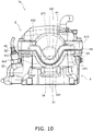
- FIG. 10 is a side view of the cylinder head 4 and the head cover 5 as seen from the cam chain compartment 17 side.
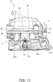
- FIG. 11 is a side view of the cylinder head 4 and the head cover 5 as seen from the opposite side of the cam chain compartment 17 side.
- the cylinder head 4 includes the first mating surface portion 41, the second mating surface portion 42, the third mating surface portion 43 and the fourth mating surface portion 44, and the first mating surface portion 41 includes the recessed portion 411.
- the head cover 5 includes the first edge portion 51, the second edge portion 52, the third edge portion 53 and the fourth edge portion 54, and the first edge portion 51 includes the protruded portion 511.
- the head cover 5 according to the second exemplary embodiment has a shape up-and-down directionally thinner than that according to the first exemplary embodiment.
- the distance from the upper end of the head cover 5 to the first straight portion 512 of the first edge portion 51 is shorter than that from the first straight portion 412 of the first mating surface portion 41 of the cylinder head 4 to the lower end of the cylinder head 4.
- the distance from the upper end of the head cover 5 to the third edge portion 53 is shorter than that from the third mating surface portion 43 of the cylinder head 4 to the lower end of the cylinder head 4.
- the engine 1b according to the second exemplary embodiment is similar to the engine 1a according to the first exemplary embodiment, and the other points will not be explained.
- the engine 1b according to the second exemplary embodiment it is also possible to achieve advantageous effects similar to those achieved in the engine 1a according to the first exemplary embodiment.
- the term “straddled vehicle” encompasses a motorcycle, an all-terrain vehicle and a snowmobile. Additionally, the term “motorcycle” encompasses a sport type motorcycle, an off-road type motorcycle, a scooter and a moped. The number of the front or rear wheels of the motorcycle is not limited to one, and may be plural.
- FIGS. 12 and 13 are side views of portion of an engine 1c according to another exemplary embodiment.
- the right side corresponds to the cam chain compartment side
- the left side corresponds to the opposite side of the cam chain compartment 17.
- the mating surface 40 of the cylinder head 4 may downwardly slant from the opposite side of the cam chain compartment 17 to the cam chain compartment side in the axial direction of the camshaft 14.
- the first mating surface portion 41 may not be provided with the protruded portion 511 described in the aforementioned exemplary embodiments.
- the entirety of the first mating surface portion 41 may extend in a direction perpendicular to the cylinder axis Ax1.
- the entirety of the first mating surface portion 41 may be located downward of the lower end of the first cam support portion 211.
- the second mating surface portion 42 may downwardly slant from the opposite side of the cam chain compartment 17 to the cam chain compartment side in the axial direction of the camshaft 14. In other words, the second mating surface portion 42 may slant obliquely upward from the first mating surface portion 41 to the opposite side of the cam chain compartment 17. Therefore, the second mating surface portion 42 may be located upward of the first mating surface portion 41.
- the third mating surface portion 43 may be located upward of the first mating surface portion 41.
- the third mating surface portion 43 may be located upward of the lower end of the first cam support portion 211.
- the third mating surface portion 43 may be located upward of the camshaft 14.
- the third mating surface portion 43 may be located upward of the first mating surface portion 41.
- the third mating surface portion 43 may extend in a direction perpendicular to the cylinder axis Ax1.
- the fourth mating surface portion 44 may downwardly slant from the opposite side of the cam chain compartment 17 to the cam chain compartment side in the axial direction of the camshaft 14. In other words, the fourth mating surface portion 44 may slant obliquely upward from the first mating surface portion 41 to the opposite side of the cam chain compartment 17. Therefore, the fourth mating surface portion 44 may be located upward of the first mating surface portion 41.
- the edge 50 of the head cover 5 may slant along the mating surface 40 of the cylinder head 4.
- the second edge portion 52 may slant along the second mating surface portion 42.
- the fourth edge portion 54 may slant along the fourth mating surface portion 54.
- the mating surface 40 of the cylinder head 4 slants, whereby the position of the first mating surface portion 41 can be made lower than that of the first cam support portion 211.
- the edge 50 of the head cover 5 slants, whereby the position of the first edge portion 51 of the head cover 5 can be made low, and the head cover 5 can be extended to a position adjacent to the cam chain compartment 17. Accordingly, it is possible to obtain advantageous effects similar to those achieved in the aforementioned exemplary embodiments.
- an engine for a straddled vehicle including a head cover made of resin
- degradation in durability of the head cover can be inhibited, and the engine can be made lightweight.
Landscapes
- Engineering & Computer Science (AREA)
- Mechanical Engineering (AREA)
- General Engineering & Computer Science (AREA)
- Chemical & Material Sciences (AREA)
- Combustion & Propulsion (AREA)
- Cylinder Crankcases Of Internal Combustion Engines (AREA)
- Valve-Gear Or Valve Arrangements (AREA)
Abstract
Description
- The present invention relates to an engine for a straddled vehicle.
- A head cover is attached to a cylinder head of an engine for a straddled vehicle. For example, in an engine of
PTL 1, a head cover made of resin is attached to a cylinder head. With the head cover made of resin, the engine can be made lightweight compared to an engine with a head cover made of metal. - PTL1: Japan Laid-open Patent Application Publication No.
2014-214665 - To make the weight of the engine further lighter, it is preferable to increase the size of the head cover made of resin and reduce the size of the cylinder head made of metal. However, it is concerned that the head cover made of resin thermally deforms at high temperatures. Thus, due to the drawback of durability, it is difficult to increase the size of the head cover made of resin. Because of this, it is not easy to sufficiently obtain an advantageous effect of lightweight by the head cover made of resin.
- It is an object of the present invention to make it possible in an engine for a straddle vehicle including a head cover made of resin to inhibit degradation in durability of the head cover and make the engine lightweight.
- An engine for a straddled vehicle according to an aspect of the present invention includes a camshaft, a cam chain, a cylinder head and a head cover. The cam chain is coupled to the camshaft. The cylinder head includes a cam support portion supporting the camshaft and a cam chain compartment in which the cam chain is disposed. The cylinder head is made of metal. The head cover is made of resin, and is attached to the cylinder head. The cylinder head includes a mating surface to be attached to the head cover.
- The mating surface includes a first mating surface portion, a second mating surface portion, a third mating surface portion and a fourth mating surface portion. The first mating surface portion is adjacent to the cam chain compartment. The third mating surface portion is located on an opposite side of the first mating surface portion. The second mating surface portion connects the first mating surface portion and the third mating surface portion. The fourth mating surface portion is located on an opposite side of the second mating surface portion, and connects the first mating surface portion and the third mating surface portion. In a cylinder axial direction of the cylinder head, a directional side from the head cover to the cylinder head is defined as downward and a directional side from the cylinder head to the head cover is defined as upward. At least portion of the first mating surface portion is located downward of a lower end of the cam support portion. At least portion of the second mating surface portion, at least portion of the third mating surface portion and at least portion of the fourth mating surface portion are located upward of the lower end of the cam support portion.
- In the engine for a straddled vehicle according to the present aspect, at least portion of the first mating surface portion of the cylinder head is located downward of the lower end of the cam support portion, and hence, the head cover can be extended downward by that much. Accordingly, the volume of the cylinder head made of metal can be reduced, whereas the volume of the head cover made of resin can be increased. As a result, the engine can be made lightweight.
- Additionally, the first mating surface portion is adjacent to the cam chain compartment having a relatively low temperature in the cylinder head. Therefore, thermal deformation of the head cover is inhibited even when the head cover made of resin is extended to a position adjacent to the cam chain compartment. Accordingly, degradation in durability of the head cover can be inhibited.
- Moreover, the cylinder head cover made of resin has a lower thermal conductivity than that made of metal. In other words, the cylinder head cover made of resin has higher heat retaining properties than that made of metal. Therefore, the head cover is downwardly extended at the first mating surface portion, whereby heat retaining properties can be enhanced in the cam chain compartment having a low temperature. Accordingly, lubricating oil can be warmed to an appropriate temperature, whereby returning of the lubricating oil can be made better.
- Furthermore, the lubricating oil is warmed, whereby it becomes easy for the lubricating oil to enter the cam support portion. Accordingly, lubrication properties can be enhanced.
- The head cover may include a first edge portion to be mated with the first mating surface portion, a second edge portion to be mated with the second mating surface portion, a third edge portion to be mated with the third mating surface portion, and a fourth edge portion to be mated with the fourth mating surface portion. At least portion of the first edge portion may be located downward of the lower end of the cam support portion. At least portion of the second edge portion, at least portion of the third edge portion, at least portion of the fourth edge portion may be located upward of the lower end of the cam support portion. In this case, the first edge portion can be extended downward of the second edge portion, the third edge portion and the fourth edge portion.
- The cylinder head may include an exhaust port. The second mating surface portion may be located above the exhaust port. The second mating surface portion may be located upward of the first mating surface portion. In this case, temperature easily gets high in a position above the exhaust port. In view of this, the second mating surface portion is disposed upward of the first mating surface portion, and can be thereby disposed away from the exhaust port. Accordingly, thermal influence on the head cover can be alleviated.
- The engine may further include a spark plug. The cylinder head may include a spark plug attachment portion to which the spark plug is attached. The spark plug attachment portion may be disposed on an opposite side of the cam chain compartment in an axial direction of the camshaft. The third mating surface portion may be located above the spark plug attachment portion. The third mating surface portion may be located upward of the first mating surface portion.
- When the third mating surface portion is located above the spark plug attachment portion, interference of the third mating surface portion with the spark plug emerges as a problem if the third mating surface portion is located in a low position. In view of this, the third mating surface portion is disposed upward of the first mating surface portion, whereby interference between the third mating surface portion and the spark plug can be avoided.
- The first mating surface portion may include a recessed portion recessed downward. At least portion of the recessed portion may be located downward of the lower end of the cam support portion. In this case, the first mating surface portion includes the recessed portion, whereby the position of at least portion of the first mating surface portion can be made lower than that of the cam support portion.
- The head cover may include a protruded portion protruded downward. The protruded portion may be attached to the recessed portion. In this case, the volume of the head cover made of resin can be increased by the amount of the protruded portion.
- A lower end of the recessed portion may be located downward of the second mating surface portion, the third mating surface portion and the fourth mating surface portion. In this case, in the head cover, a portion to be fitted to the recessed portion can be extended downwardly of the other portion.
- The second mating surface portion, the third mating surface portion and the fourth mating surface portion may be located upward of the lower end of the cam support portion. In this case, in the head cover, a portion to be fitted to the recessed portion can be extended downward of the other portion.
- The mating surface may downwardly slant from the opposite side of the cam chain compartment to the cam chain compartment in the axial direction of the camshaft. In this case, the mating surface slants, whereby the position of at least portion of the first mating surface portion can be made lower than that of the cam support portion.
- The head cover may include an edge that is attached to the mating surface of the cylinder head. The edge may slant along the mating surface of the cylinder head. In this case, the edge of the head cover slants, whereby the head cover can be extended to a position adjacent to the cam chain compartment.
- The head cover may include a projection that sticks out from an inner surface of the head cover. The projection may be provided to downwardly drip a lubricating oil to the cam chain. In this case, when the head cover exerts high heat retaining properties in the interior thereof, the lubricating oil can be smoothly dripped downward from the projection. Accordingly, lubrication properties can be enhanced.
- The head cover may include a chain restraining portion. The chain restraining portion may stick out from the inner surface of the head cover, and may extend to a position lateral to the cam chain. The chain restraining portion may have a thickness smaller than an interval between a pair of plates of the cam chain or a width of a bushing of the cam chain. In this case, upward disengagement of the cam chain can be prevented by the chain restraining portion. Additionally, the head cover is made of resin, whereby the chain restraining portion can be easily formed with small thickness.
- The engine may be of an SOHC type. In this case, the position of the mating surface of the cylinder head can be made low more easily in the SOHC engine than in a DOHC engine. Therefore, at least portion of the first mating surface portion can be easily located downward of the cam support portion.
- The engine may be of an air cooling type. Here in the engine of the air cooling type, the temperature of the head cover is likely to get higher than that of the lubricating oil. Therefore, the lubricating oil is smoothly circulated, and the head cover can be efficiently cooled by the lubricating oil.
- The head cover may be made of fiber reinforced resin. In this case, the head cover can be inhibited from being deformed by thermal influence.
- According to the present invention, in an engine for a straddled vehicle including a head cover made of resin, degradation in durability of the head cover can be inhibited, and the engine can be made lightweight.
-
-
FIG. 1 is a side view of a straddled vehicle according to a first exemplary embodiment. -
FIG. 2 is a cross-sectional view of portion of an engine for the straddled vehicle according to the first exemplary embodiment. -
FIG. 3 is an exploded perspective view of a cylinder head and a head cover of the engine according to the first exemplary embodiment. -
FIG. 4 is s side view of the cylinder head and the head cover as seen from a cam chain compartment side. -
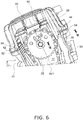
FIG. 5 is a side view of the cylinder head and the head cover as seen from the opposite side of the cam chain compartment side. -
FIG. 6 is a cross-sectional view of the cylinder head and the head cover. -
FIG. 7 is a cross-sectional view ofFIG. 6 taken along VII-VII. -
FIG. 8 is a side view of a straddle vehicle according to a second exemplary embodiment. -
FIG. 9 is an exploded perspective view of a cylinder head and a head cover of an engine according to the second exemplary embodiment. -
FIG. 10 is s side view of the cylinder head and the head cover as seen from a cam chain compartment side. -
FIG. 11 is a side view of the cylinder head and the head cover as seen from the opposite side of the cam chain compartment side. -
FIG. 12 is a side view of portion of an engine according to another exemplary embodiment. -
FIG. 13 is a side view of portion of the engine according to the another exemplary embodiment. - An exemplary embodiment of the present invention will be hereinafter explained with reference to drawings.
FIG. 1 is a side view of a straddledvehicle 100 according to a first exemplary embodiment. In the following explanation, the terms "front", "rear", "left" and "right" are defined as meaning front, rear, left and right directions seen from a rider riding on the straddledvehicle 100. The straddledvehicle 100 is a so-called sport vehicle. The straddledvehicle 100 includes afuel tank 102, aseat 103, anengine 1a and avehicle body frame 105. - The
fuel tank 102, theseat 103 and theengine 1a are supported by thevehicle body frame 105. Thefuel tank 102 is disposed in front of theseat 103. Theengine 1a is disposed under thefuel tank 102. - The straddled
vehicle 100 includes ahead pipe 106, afront fork 107, afront wheel 108, ahandle 109 and aheadlight unit 110. Thehead pipe 106 is disposed in front of thefuel tank 102. Thefront fork 107 includes asteering shaft 115 andsuspensions 116. The steeringshaft 115 is turnably supported by thehead pipe 106. Thesuspensions 116 are connected to the lower portion of thesteering shaft 115. - The
front wheel 108 is rotatably supported by thefront fork 107. Thehandle 109 is connected to the upper portion of thesteering shaft 115. Theheadlight unit 110 is disposed in front of thehead pipe 106. - The straddled
vehicle 100 includes aswing arm 111 and arear wheel 112. Theswing arm 111 backwardly extends from thevehicle body frame 105. Theswing arm 111 is connected to thevehicle body frame 105 while being pivotable up and down. Therear wheel 112 is rotatably supported by the rear portion of theswing arm 111. -
FIG. 2 is a cross-sectional view of portion of theengine 1a according to the first exemplary embodiment. In the present exemplary embodiment, theengine 1a is a single-cylinder engine of an air cooling type. It should be noted that theengine 1a may be of a water cooling type. Theengine 1a may be a multiple-cylinder engine. As shown inFIG. 2 , theengine 1a includes acrankcase 2, acylinder body 3, acylinder head 4 and ahead cover 5. - The
crankcase 2 accommodates a crankshaft (not shown in the drawings). Thecylinder body 3 is connected to thecrankcase 2. Thecylinder body 3 may be integrated with or separated from thecrankcase 2. Thecylinder body 3 is provided with a plurality of coolingfins 301. It should be noted that in the drawings,reference numeral 301 is assigned to only portion of theplural cooling fins 301 without being assigned to theother cooling fins 301. Thecylinder body 3 accommodates apiston 7. Thepiston 7 is coupled to the crankshaft through a connectingrod 8. - It should be noted that in the present exemplary embodiment, in the direction of a cylinder axis Ax1 of the
cylinder head 4, one directional side from thehead cover 5 to thecylinder head 4 is defined as "downward", whereas the other directional side from thecylinder head 4 to thehead cover 5 is defined as "upward". - The
cylinder head 4 is disposed above thecylinder body 3. Thecylinder head 4 is attached to thecylinder body 3. Thehead cover 5 is disposed above thecylinder head 4. Thehead cover 5 is attached to thecylinder head 4. Thehead cover 5 is made of resin. This resin may be, for instance, PA (polyamide). Alternatively, this resin may be a type of resin other than PA. Thehead cover 5 is made of fiber reinforced resin. For example, this fiber reinforced resin may be glass fiber reinforced resin. Alternatively, this fiber reinforced resin may be of a type using a fiber other than glass. - The
cylinder head 4 is made of metal. Thecylinder head 4 is made of, for instance, aluminum alloy. It should be noted that the material of which thecylinder head 4 is made is not limited to aluminum alloy and may be another type of metal. Thecylinder head 4 may be separated from or integrated with thecylinder body 3. - The
cylinder head 4 includes acombustion chamber 11. Aspark plug 12 is attached to thecylinder head 4. The tip end of thespark plug 12 is disposed to face thecombustion chamber 11. The base end of thespark plug 12 is disposed outside theengine 1a. - A
valve actuating mechanism 13 is accommodated in thecylinder head 4 and thehead cover 5. Thevalve actuating mechanism 13 is a mechanism that opens and closes an intake valve and an exhaust valve (both of which are not shown in the drawings). Thevalve actuating mechanism 13 employs a mechanism of an SOHC (Single OverHead Camshaft) type. - The
valve actuating mechanism 13 includes acamshaft 14, anintake rocker arm 15 and anexhaust rocker arm 16. A center axis Ax2 of the camshaft 14 (hereinafter referred to as "cam axis Ax2") is arranged perpendicular to the cylinder axis Ax1. Thecamshaft 14 is supported by thecylinder head 4. Thecamshaft 14 includes afirst shaft end 141 and asecond shaft end 142. Thefirst shaft end 141 is one end of thecamshaft 14 in the direction of the cam axis Ax2. Thesecond shaft end 142 is the other end of thecamshaft 14 in the direction of the cam axis Ax2. - The
cylinder head 4 includes afirst support wall 21 and asecond support wall 22. Thefirst support wall 21 and thesecond support wall 22 are integrated with thecylinder head 4. Thefirst support wall 21 supports thefirst shaft end 141 of thecamshaft 14. Thesecond support wall 22 supports thesecond shaft end 142 of thecamshaft 14. Thefirst support wall 21 includes a firstcam support portion 211. The firstcam support portion 211 is a hole provided in thefirst support wall 21. Afirst bearing 23 is attached to the firstcam support portion 211. Thefirst support wall 21 supports thefirst shaft end 141 through thefirst bearing 23. - The
second support wall 22 includes a secondcam support portion 221. The secondcam support portion 221 is a hole provided in thesecond support wall 22. Asecond bearing 24 is attached to the secondcam support portion 221. Thesecond support wall 22 supports thesecond shaft end 142 through thesecond bearing 24. - A
sprocket 25 is attached to thefirst shaft end 141. Acam chain 26 is wound about thesprocket 25. In other words, thecam chain 26 is coupled to thecamshaft 14 through thesprocket 25. - The
cylinder head 4 and thecylinder body 3 are provided with acam chain compartment 17. Thecam chain 26 is disposed in thecam chain compartment 17. Thecamshaft 14 is coupled to the crankshaft through thecam chain 26. Rotation of the crankshaft is transmitted to thecamshaft 14 through thecam chain 26, whereby thecamshaft 14 is rotated. It should be noted in the present exemplary embodiment that in the direction of the cam axis Ax2, a directional side from thesecond shaft end 142 to thefirst shaft end 141 is referred to as "cam chain compartment side". - The
camshaft 14 includes anintake cam 143 and anexhaust cam 144. Theintake cam 143 and theexhaust cam 144 are disposed in alignment in the direction of the cam axis Ax2. Theintake cam 143 and theexhaust cam 144 are disposed between thefirst support wall 21 and thesecond support wall 22. - The
intake rocker arm 15 and theexhaust rocker arm 16 are disposed above thecamshaft 14. Theintake rocker arm 15 is disposed above theintake cam 143. Theintake rocker arm 15 makes contact with theintake cam 143. When thecamshaft 14 is rotated, theintake rocker arm 15 is pressed by theintake cam 143. Accordingly, theintake rocker arm 15 is pivoted, whereby the intake valve is driven. - The
exhaust rocker arm 16 is disposed above theexhaust cam 144. Theexhaust rocker arm 16 makes contact with theexhaust cam 144. When thecamshaft 14 is rotated, theexhaust rocker arm 16 is pressed by theexhaust cam 144. Accordingly, theexhaust rocker arm 16 is pivoted, whereby the exhaust valve is driven. - As shown in
FIG. 2 , theengine 1a is provided with anoil supply channel 27. Theoil supply channel 27 is disposed across thecrankcase 2, thecylinder body 3 and thecylinder head 4. Theengine 1a includes anoil pump 28. Theoil pump 28 supplies lubricating oil to thevalve actuating mechanism 13 through theoil supply channel 27. The lubricating oil is supplied to the interior of thecylinder head 4 from the interior of thecrankcase 2 through theoil supply channel 27. After lubricating thevalve actuating mechanism 13, the lubricating oil returns to the interior of thecrankcase 2 through thecam chain compartment 17. -
FIG. 3 is an exploded perspective view of thecylinder head 4 and thehead cover 5.FIG. 4 is a side view of thecylinder head 4 and thehead cover 5 as seen from the cam chain compartment side.FIG. 5 is a side view of thecylinder head 4 and thehead cover 5 as seen from the opposite side of the cam chain compartment side. - As shown in
FIGS. 3 to 5 , thecylinder head 4 includes a plurality of coolingfins 401. It should be noted that in the drawings,reference numeral 401 is assigned to only portion of theplural cooling fins 401 without being assigned to theother cooling fins 401. As shown inFIGS. 2 and5 , thecylinder head 4 includes a sparkplug attachment portion 31. The sparkplug attachment portion 31 is disposed on the opposite side of thecam chain compartment 17 in the axial direction of thecamshaft 14. Thespark plug 12 is attached to the sparkplug attachment portion 31. - As shown in
FIG. 5 , thecylinder head 4 includes anexhaust port 32 and anintake port 33. Theexhaust port 32 and theintake port 33 are communicated with theaforementioned combustion chamber 11. Fuel and air are supplied to thecombustion chamber 11 through theintake port 33. Exhaust gas in the interior of thecombustion chamber 11 is discharged through theexhaust port 32. - As shown in
FIG. 3 , thecylinder head 4 includes amating surface 40 to be attached to thehead cover 5. Themating surface 40 of thecylinder head 4 is attached to thehead cover 5 through agasket 34 shown inFIG. 2 . - As shown in
FIGS. 3 and4 , themating surface 40 of thecylinder head 4 includes a firstmating surface portion 41, a secondmating surface portion 42, a thirdmating surface portion 43 and a fourthmating surface portion 44. The firstmating surface portion 41 is disposed in adjacent to thecam chain compartment 17. The firstmating surface portion 41 is located downward of the upper end of thefirst support wall 21. The firstmating surface portion 41 includes a recessedportion 411, a firststraight portion 412 and a secondstraight portion 413. The recessedportion 411 is located between the firststraight portion 412 and the secondstraight portion 413. The recessedportion 411 is recessed downward. The lower end of the recessedportion 411 is located downward of the lower end of the firstcam support portion 211. The lower end of the recessedportion 411 is located downward of the secondmating surface portion 42, the thirdmating surface portion 43 and the fourthmating surface portion 44. - The first
straight portion 412 and the secondstraight portion 413 extend in a direction perpendicular to the cylinder axis Ax1. The firststraight portion 412 and the secondstraight portion 413 are located upward of the lower end of the firstcam support portion 211. The firststraight portion 412 and the secondstraight portion 413 are located upward of the cam axis Ax2. The firststraight portion 412 and the secondstraight portion 413 are located downward of the upper end of the firstcam support portion 211. - The second
mating surface portion 42 connects the firstmating surface portion 41 and the thirdmating surface portion 43. The secondmating surface portion 42 is located above theexhaust port 32. The secondmating surface portion 42 is located upward of the lower end of the recessedportion 411. The secondmating surface portion 42 is located upward of the lower end of the firstcam support portion 211. The secondmating surface portion 42 is located upward of the cam axis Ax2. The secondmating surface portion 42 is located downward of the upper end of the firstcam support portion 211. The secondmating surface portion 42 extends in a direction perpendicular to the cylinder axis Ax1. The secondmating surface portion 42 is located at the same height as the firststraight portion 412 and the secondstraight portion 413. - As shown in
FIG. 5 , the thirdmating surface portion 43 is located on the opposite side of the firstmating surface portion 41. The thirdmating surface portion 43 is located above the sparkplug attachment portion 31. Thecamshaft 14 is disposed between the firstmating surface portion 41 and the thirdmating surface portion 43. The thirdmating surface portion 43 is located upward of the lower end of the recessedportion 411. The thirdmating surface portion 43 is located upward of the lower end of the firstcam support portion 211. The thirdmating surface portion 43 is located upward of the cam axis Ax2. The thirdmating surface portion 43 is located downward of the upper end of the firstcam support portion 211. The thirdmating surface portion 43 extends in a direction perpendicular to the cylinder axis Ax1. The thirdmating surface portion 43 is located at the same height as the secondmating surface portion 42. The thirdmating surface portion 43 is located at the same height as the firststraight portion 412 and the secondstraight portion 413. - As shown in
FIG. 3 , the fourthmating surface portion 44 is located on the opposite side of the secondmating surface portion 42. The fourthmating surface portion 44 connects the firstmating surface portion 41 and the thirdmating surface portion 43. The fourthmating surface portion 44 is located above theintake port 33. Thecamshaft 14 is disposed between the secondmating surface portion 42 and the fourthmating surface portion 44. The fourthmating surface portion 44 is located upward of the lower end of the recessedportion 411. The fourthmating surface portion 44 is located upward of the lower end of the firstcam support portion 211. The fourthmating surface portion 44 is located upward of the cam axis Ax2. The fourthmating surface portion 44 is located downward of the upper end of the firstcam support portion 211. The fourthmating surface portion 44 extends in a direction perpendicular to the cylinder axis Ax1. The fourthmating surface portion 44 is located at the same height as the secondmating surface portion 42. The fourthmating surface portion 44 is located at the same height as the thirdmating surface portion 43. The fourthmating surface portion 44 is located at the same height as the firststraight portion 412 and the secondstraight portion 413. - As shown in
FIG. 3 , thehead cover 5 includes anedge 50 to be attached to themating surface 40 of thecylinder head 4. Theedge 50 of thehead cover 5 is attached to themating surface 40 of thecylinder head 4 through thegasket 34. Theedge 50 of thehead cover 5 includes afirst edge portion 51. Thefirst edge portion 51 is attached to the firstmating surface portion 41 of thecylinder head 4. - The
first edge portion 51 includes a protrudedportion 511, a firststraight portion 512 and a secondstraight portion 513. The protrudedportion 511 is located between the firststraight portion 512 and the secondstraight portion 513. The protrudedportion 511 is protruded downward. The protrudedportion 511 is attached to the recessedportion 411. The lower end of the protrudedportion 511 is located downward of the cam axis Ax2. The firststraight portion 512 and the secondstraight portion 513 extend in a direction perpendicular to the cylinder axis Ax1. The firststraight portion 512 and the secondstraight portion 513 are located upward of the cam axis Ax2. The firststraight portion 512 is attached to the firststraight portion 412 of thecylinder head 4. The secondstraight portion 513 is attached to the secondstraight portion 413 of thecylinder head 4. - The
edge 50 of thehead cover 5 includes asecond edge portion 52. Thesecond edge portion 52 is attached to the secondmating surface portion 42 of thecylinder head 4. Thesecond edge portion 52 extends in a direction perpendicular to the cylinder axis Ax1. Thesecond edge portion 52 is located upward of the lower end of the protrudedportion 511. Thesecond edge portion 52 is located at the same height as the firststraight portion 512 and the secondstraight portion 513. - As shown in
FIG. 5 , theedge 50 of thehead cover 5 includes athird edge portion 53. Thethird edge portion 53 is attached to the thirdmating surface portion 43 of thecylinder head 4. Thethird edge portion 53 extends in a direction perpendicular to the cylinder axis Ax1. Thethird edge portion 53 is located upward of the lower end of the protrudedportion 511. Thethird edge portion 53 is located at the same height as thesecond edge portion 52. Thethird edge portion 53 is located at the same height as the firststraight portion 512 and the secondstraight portion 513. - The
edge 50 of thehead cover 5 includes afourth edge portion 54. Thefourth edge portion 54 is attached to the fourthmating surface portion 44 of thecylinder head 4. Thefourth edge portion 54 extends in a direction perpendicular to the cylinder axis Ax1. Thefourth edge portion 54 is located upward of the lower end of the protrudedportion 511. Thefourth edge portion 54 is located at the same height as thesecond edge portion 52. Thefourth edge portion 54 is located at the same height as thethird edge portion 53. Thefourth edge portion 54 is located at the same height as the firststraight portion 512 and the secondstraight portion 513. -
FIG. 6 is a cross-sectional view of thecylinder head 4 and thehead cover 5. As shown inFIG. 6 , thehead cover 5 includes a plurality ofprojections 55. Theplural projections 55 downwardly stick out from the inner surface of thehead cover 5. The tips of theprojections 55 face thecam chain 26. In the interior of the engine, the lubricating oil is drawn from the interior of thecrankcase 22 by an oil pump (not shown in the drawings) and is supplied to the interior of thehead cover 5. The lubricating oil supplied to the interior of thehead cover 5 flows along theprojections 55 and downwardly drips toward thecam chain 26. Accordingly, the lubricating oil is supplied to thecam chain 26. - The
head cover 5 includes achain restraining portion 56. Thechain restraining portion 56 downwardly sticks out from the inner surface of thehead cover 5 and extends to a position lateral to thecam chain 26. Therefore, even when upwardly disengaged from thesprocket 25, thecam chain 26 makes contact with thechain restraining portion 56 whereby upward disengagement of thecam chain 26 is restrained. Accordingly, upward disengagement of thecam chain 26 can be prevented. -
FIG. 7 is a cross-sectional view ofFIG. 6 taken along VII-VII. As shown inFIG. 7 , the tip of thechain restraining portion 56 has a thin plate shape. The thickness of the tip of thechain restraining portion 56 is smaller than a gap between a pair ofplates cam chain 26. The tip of thechain restraining portion 56 is disposed in opposition to abushing 263 disposed between the pair ofplates cam chain 26. The thickness of the tip of thechain restraining portion 56 is smaller than the width of thebushing 263. - In the
engine 1a for a straddled vehicle according to the present exemplary embodiment explained above, the recessedportion 411 of the firstmating surface portion 41 of thecylinder head 4 is located downward of the firstcam support portion 211, and hence, the protrudedportion 511 of thehead cover 5 can be extended downward by that much. Accordingly, the volume of thecylinder head 4 made of metal can be reduced, whereas the volume of thehead cover 5 made of resin can be increased. As a result, theengine 1a can be made lightweight. - The first
mating surface portion 41 is disposed in adjacent to thecam chain compartment 17 having a relatively low temperature in thecylinder head 4. Therefore, thermal deformation of thehead cover 5 is inhibited even when the protrudedportion 511 of thehead cover 5 made of resin is extended to a position adjacent to thecam chain compartment 17. Accordingly, degradation in durability of thehead cover 5 can be inhibited. - The
head cover 5 made of resin has higher heat retaining properties than thecylinder head 4 made of metal. Therefore, the heat retaining properties inside thecylinder head 4 are enhanced by increase in volume of thehead cover 5 made of resin. Thus, the temperature of the lubricating oil is increased inside thecylinder head 4, whereby the viscosity of the lubricating oil is lowered. In other words, the lubricating oil can be smoothly circulated inside thecylinder head 4. As a result, friction loss can be reduced, while efficiency of recovering the lubricating oil can be enhanced. - The second
mating surface portion 42 is located above theexhaust port 32, whereby the temperature thereof is likely to be high. In view of this, the secondmating surface portion 42 is disposed upward of the firstmating surface portion 41, and can be thereby disposed away from theexhaust port 32. Accordingly, thermal influence on thehead cover 5 from theexhaust port 32 can be alleviated. - The third
mating surface portion 43 is located above the sparkplug attachment portion 31. Therefore, if the thirdmating surface portion 43 is located in a low position, interference thereof with thespark plug 12 emerges as a problem. In view of this, the thirdmating surface portion 43 is disposed upward of the firstmating surface portion 41, and can be thereby disposed away from the sparkplug attachment portion 31. Accordingly, interference between the thirdmating surface portion 43 and thespark plug 12 can be avoided. - The
engine 1a according to the present exemplary embodiment is an SOHC engine. The position of themating surface 40 of thecylinder head 4 can be made low in theSOHC engine 1a more easily than in a DOHC engine. Therefore, the recessedportion 411 of the firstmating surface portion 41 can be easily located downward of the support wall. - The
engine 1a according to the present exemplary embodiment is of an air cooling type. In the engine of the air cooling type, the temperature of thehead cover 5 is likely to get higher than that of the lubricating oil. Therefore, when the lubricating oil is smoothly circulated, thehead cover 5 can be efficiently cooled by the lubricating oil. - When the
head cover 5 exerts high heat retaining properties in the interior thereof, the viscosity of the lubricating oil becomes low. Therefore, the lubricating oil can be smoothly dripped downward from theprojections 55. Accordingly, lubrication properties can be enhanced. - The
head cover 5 is provided with thechain restraining portion 56. The thickness of the tip of thechain restraining portion 56 is smaller than the gap between the pair ofplates cam chain 26. In the present exemplary embodiment, thehead cover 5 is made of resin. Therefore, thechain restraining portion 56 can be easily formed with small thickness. - Next, a straddled vehicle according to a second exemplary embodiment will be explained.
FIG. 8 is a side view of a straddledvehicle 200 according to the second exemplary embodiment. As shown inFIG. 8 , the straddledvehicle 200 according to the second exemplary embodiment is a scooter type vehicle. The straddledvehicle 200 includes asteering device 201, avehicle body 202, apower unit 203, afront wheel 204, arear wheel 205 and aseat 206. - The
steering device 201 includes afront fork 207. Thefront fork 207 supports thefront wheel 204 such that thefront wheel 204 is rotatable. Ahandle 208 is provided on the upper portion of thesteering device 201. - The
vehicle body 202 includes afront cover 231, aleg shield 232, arear cover 233 and alower cover 234. Thefront cover 231 covers thesteering device 201 from the front. Theleg shield 232 covers thesteering device 201 from the back. Theleg shield 232 is attached to thefront cover 231. Therear cover 233 is disposed behind theleg shield 232. Therear cover 233 is disposed under theseat 206. Thelower cover 234 is disposed between theleg shield 232 and therear cover 233. The upper surface of thelower cover 234 includes afootboard 235. Thefootboard 235 is disposed such that the legs of a rider are put thereon. Thefootboard 235 has a flat shape. Thefootboard 235 may be entirely flat in a vehicle width direction. Alternatively, thefootboard 235 may have an upwardly protruding shape in the vehicle width directional middle portion thereof. - The
power unit 203 is disposed under theseat 206. Thepower unit 203 is pivotably supported by thevehicle body 202. Thepower unit 203 supports therear wheel 205 such that therear wheel 205 is rotatable. Thepower unit 203 includes anengine 1b. Theengine 1b includes thecylinder head 4 and thehead cover 5. Thecylinder head 4 and thehead cover 5 are disposed under theseat 206. The cylinder axis Ax1 of thecylinder head 4 is arranged approximately horizontally. For example, an angle of the cylinder axis Ax1 with respect to a horizontal direction is greater than or equal to 0 degrees and less than or equal to 45 degrees. -
FIG. 9 is an exploded perspective view of theengine 1b according to the second exemplary embodiment.FIG. 10 is a side view of thecylinder head 4 and thehead cover 5 as seen from thecam chain compartment 17 side.FIG. 11 is a side view of thecylinder head 4 and thehead cover 5 as seen from the opposite side of thecam chain compartment 17 side. - As shown in
FIGS. 9 to 11 , similarly to the first exemplary embodiment, thecylinder head 4 includes the firstmating surface portion 41, the secondmating surface portion 42, the thirdmating surface portion 43 and the fourthmating surface portion 44, and the firstmating surface portion 41 includes the recessedportion 411. Similarly to the first exemplary embodiment, thehead cover 5 includes thefirst edge portion 51, thesecond edge portion 52, thethird edge portion 53 and thefourth edge portion 54, and thefirst edge portion 51 includes the protrudedportion 511. - The
head cover 5 according to the second exemplary embodiment has a shape up-and-down directionally thinner than that according to the first exemplary embodiment. For example, as shown inFIG. 10 , the distance from the upper end of thehead cover 5 to the firststraight portion 512 of thefirst edge portion 51 is shorter than that from the firststraight portion 412 of the firstmating surface portion 41 of thecylinder head 4 to the lower end of thecylinder head 4. As shown inFIG. 11 , the distance from the upper end of thehead cover 5 to thethird edge portion 53 is shorter than that from the thirdmating surface portion 43 of thecylinder head 4 to the lower end of thecylinder head 4. - Regarding the other points, the
engine 1b according to the second exemplary embodiment is similar to theengine 1a according to the first exemplary embodiment, and the other points will not be explained. In theengine 1b according to the second exemplary embodiment, it is also possible to achieve advantageous effects similar to those achieved in theengine 1a according to the first exemplary embodiment. - One exemplary embodiment of the present invention has been explained above. However, the present invention is not limited to the aforementioned exemplary embodiment, and a variety of changes can be made without departing from the gist of the present invention.
- The term "straddled vehicle" encompasses a motorcycle, an all-terrain vehicle and a snowmobile. Additionally, the term "motorcycle" encompasses a sport type motorcycle, an off-road type motorcycle, a scooter and a moped. The number of the front or rear wheels of the motorcycle is not limited to one, and may be plural.
- The shape of the
mating surface 40 of thecylinder head 4 is not limited to that in the aforementioned exemplary embodiments, and may be changed. For example,FIGS. 12 and13 are side views of portion of anengine 1c according to another exemplary embodiment. InFIG. 12 , the right side corresponds to the cam chain compartment side, whereas the left side corresponds to the opposite side of thecam chain compartment 17. As shown inFIGS. 12 and13 , themating surface 40 of thecylinder head 4 may downwardly slant from the opposite side of thecam chain compartment 17 to the cam chain compartment side in the axial direction of thecamshaft 14. - In this case, the first
mating surface portion 41 may not be provided with the protrudedportion 511 described in the aforementioned exemplary embodiments. In other words, the entirety of the firstmating surface portion 41 may extend in a direction perpendicular to the cylinder axis Ax1. The entirety of the firstmating surface portion 41 may be located downward of the lower end of the firstcam support portion 211. - The second
mating surface portion 42 may downwardly slant from the opposite side of thecam chain compartment 17 to the cam chain compartment side in the axial direction of thecamshaft 14. In other words, the secondmating surface portion 42 may slant obliquely upward from the firstmating surface portion 41 to the opposite side of thecam chain compartment 17. Therefore, the secondmating surface portion 42 may be located upward of the firstmating surface portion 41. - The third
mating surface portion 43 may be located upward of the firstmating surface portion 41. The thirdmating surface portion 43 may be located upward of the lower end of the firstcam support portion 211. The thirdmating surface portion 43 may be located upward of thecamshaft 14. The thirdmating surface portion 43 may be located upward of the firstmating surface portion 41. The thirdmating surface portion 43 may extend in a direction perpendicular to the cylinder axis Ax1. - The fourth
mating surface portion 44 may downwardly slant from the opposite side of thecam chain compartment 17 to the cam chain compartment side in the axial direction of thecamshaft 14. In other words, the fourthmating surface portion 44 may slant obliquely upward from the firstmating surface portion 41 to the opposite side of thecam chain compartment 17. Therefore, the fourthmating surface portion 44 may be located upward of the firstmating surface portion 41. - The
edge 50 of thehead cover 5 may slant along themating surface 40 of thecylinder head 4. Detailedly, thesecond edge portion 52 may slant along the secondmating surface portion 42. Similarly to thesecond edge portion 52, thefourth edge portion 54 may slant along the fourthmating surface portion 54. - In this case, the
mating surface 40 of thecylinder head 4 slants, whereby the position of the firstmating surface portion 41 can be made lower than that of the firstcam support portion 211. Additionally, theedge 50 of thehead cover 5 slants, whereby the position of thefirst edge portion 51 of thehead cover 5 can be made low, and thehead cover 5 can be extended to a position adjacent to thecam chain compartment 17. Accordingly, it is possible to obtain advantageous effects similar to those achieved in the aforementioned exemplary embodiments. - According to the present invention, in an engine for a straddled vehicle including a head cover made of resin, degradation in durability of the head cover can be inhibited, and the engine can be made lightweight.
-
- 14
- Camshaft
- 26
- Cam chain
- 211
- Cam support portion
- 17
- Cam chain compartment
- 4
- Cylinder head
- 5
- Head cover
- 40
- Mating surface
- 41
- First mating surface portion
- 32
- Exhaust port
- 42
- Second mating surface portion
- 12
- Spark plug
- 31
- Spark plug attachment portion
- 43
- Third mating surface portion
- 411
- Recessed portion
- 511
- Protruded portion
- 50
- Edge
- 55
- Projection
- 56
- Chain restraining portion
Claims (15)
- An engine for a straddled vehicle comprising:a camshaft;a cam chain coupled to the camshaft;a cylinder head made of metal, the cylinder head including a cam support portion supporting the camshaft and a cam chain compartment in which the cam chain is disposed; anda head cover made of resin, the head cover being attached to the cylinder head, whereinthe cylinder head includes a mating surface to be attached to the head cover,the mating surface includes a first mating surface portion, a second mating surface portion, a third mating surface portion and a fourth mating surface portion,the first mating surface portion is adjacent to the cam chain compartment,the third mating surface portion is located on an opposite side of the first mating surface portion,the second mating surface portion connects the first mating surface portion and the third mating surface portion,the fourth mating surface portion is located on an opposite side of the second mating surface portion, the fourth mating surface portion connects the first mating surface portion and the third mating surface portion, andwhere in a cylinder axial direction of the cylinder head, a directional side from the head cover to the cylinder head is defined as downward and a directional side from the cylinder head to the head cover is defined as upward,at least portion of the first mating surface portion is located downward of a lower end of the cam support portion, andat least portion of the second mating surface portion, at least portion of the third mating surface portion and at least portion of the fourth mating surface portion are located upward of the lower end of the cam support portion.
- The engine for a straddled vehicle according to claim 1, wherein
the head cover includesa first edge portion to be mated with the first mating surface portion,a second edge portion to be mated with the second mating surface portion,a third edge portion to be mated with the third mating surface portion, anda fourth edge portion to be mated with the fourth mating surface portion,at least portion of the first edge portion is located downward of the lower end of the cam support portion, and
at least portion of the second edge portion, at least portion of the third edge portion, at least portion of the fourth edge portion are located upward of the lower end of the cam support portion. - The engine for a straddled vehicle according to claim 1 or 2, wherein
the cylinder head includes an exhaust port,
the second mating surface portion is located above the exhaust port, and
the second mating surface portion is located upward of the first mating surface portion. - The engine for a straddled vehicle according to any of claims 1 to 3, further comprising:a spark plug, whereinthe cylinder head includes a spark plug attachment portion to which the spark plug is attached,the spark plug attachment portion is disposed on an opposite side of the cam chain compartment in an axial direction of the camshaft,the third mating surface portion is located above the spark plug attachment portion, andthe third mating surface portion is located upward of the first mating surface portion.
- The engine for a straddled vehicle according to any of claims 1 to 4, wherein the first mating surface portion includes a recessed portion, the recessed portion is recessed downward, and at least portion of the recessed portion is located downward of the lower end of the cam support portion.
- The engine for a straddled vehicle according to claim 5, wherein
the head cover includes a protruded portion, the protruded portion is protruded downward, and the protruded portion is attached to the recessed portion. - The engine for a straddled vehicle according to claim 5 or 6, wherein a lower end of the recessed portion is located downward of the second mating surface portion, the third mating surface portion and the fourth mating surface portion.
- The engine for a straddled vehicle according to any of claims 5 to 7, wherein the second mating surface portion, the third mating surface portion and the fourth mating surface portion are located upward of the lower end of the cam support portion.
- The engine for a straddled vehicle according to any of claims 1 to 4, wherein the mating surface downwardly slants from the opposite side of the cam chain compartment to the cam chain compartment in the axial direction of the camshaft.
- The engine for a straddled vehicle according to claim 9, wherein the head cover includes an edge, the edge is attached to the mating surface of the cylinder head, and the edge slants along the mating surface of the cylinder head.
- The engine for a straddled vehicle according to any of claims 1 to 10, wherein the head cover includes a projection, and the projection sticks out from an inner surface of the head cover so as to downwardly drip a lubricating oil to the cam chain.
- The engine for a straddled vehicle according to any of claims 1 to 11, wherein
the head cover includes a chain restraining portion, the chain restraining portion sticks out from the inner surface of the head cover, the chain restraining portion extends to a position lateral to the cam chain, and
the chain restraining portion has a thickness smaller than an interval between a pair of plates of the cam chain or a width of a bushing of the cam chain. - The engine for a straddled vehicle according to any of claims 1 to 12, wherein the engine is of an SOHC type.
- The engine for a straddled vehicle according to any of claims 1 to 13, wherein the engine is of an air cooling type.
- The engine for a straddled vehicle according to any of claims 1 to 14, wherein the head cover is made of fiber reinforced resin.
Applications Claiming Priority (2)
| Application Number | Priority Date | Filing Date | Title |
|---|---|---|---|
| JP2015191510A JP2018188960A (en) | 2015-09-29 | 2015-09-29 | Engine for saddle type vehicle |
| PCT/JP2016/078705 WO2017057505A1 (en) | 2015-09-29 | 2016-09-28 | Engine for saddled vehicles |
Publications (3)
| Publication Number | Publication Date |
|---|---|
| EP3239510A1 true EP3239510A1 (en) | 2017-11-01 |
| EP3239510A4 EP3239510A4 (en) | 2018-04-11 |
| EP3239510B1 EP3239510B1 (en) | 2020-01-08 |
Family
ID=58427494
Family Applications (1)
| Application Number | Title | Priority Date | Filing Date |
|---|---|---|---|
| EP16851676.3A Active EP3239510B1 (en) | 2015-09-29 | 2016-09-28 | Engine for straddled vehicles |
Country Status (5)
| Country | Link |
|---|---|
| EP (1) | EP3239510B1 (en) |
| JP (1) | JP2018188960A (en) |
| BR (1) | BR112017020987B1 (en) |
| TW (1) | TWI624588B (en) |
| WO (1) | WO2017057505A1 (en) |
Family Cites Families (14)
| Publication number | Priority date | Publication date | Assignee | Title |
|---|---|---|---|---|
| JPS5833960B2 (en) * | 1977-04-21 | 1983-07-23 | トヨタ自動車株式会社 | Structure to prevent oil leakage from oil supply hole |
| JPH01148034U (en) * | 1988-03-31 | 1989-10-13 | ||
| EP0599802A1 (en) * | 1992-11-20 | 1994-06-01 | Franz Dipl.Ing.Dr. Laimböck | Headcylinder with valve drive for combustion engine |
| JPH09144994A (en) * | 1995-11-16 | 1997-06-03 | Nissan Motor Co Ltd | Internal combustion engine head cover structure |
| JPH11182368A (en) * | 1997-12-18 | 1999-07-06 | Honda Motor Co Ltd | Engine head structure |
| JP4025667B2 (en) * | 2003-03-18 | 2007-12-26 | 本田技研工業株式会社 | Overhead cam type engine |
| JP4578363B2 (en) * | 2005-09-15 | 2010-11-10 | Udトラックス株式会社 | Engine rocker cover |
| JP4619327B2 (en) * | 2006-07-20 | 2011-01-26 | 本田技研工業株式会社 | Engine head structure |
| JP2013231385A (en) * | 2012-04-27 | 2013-11-14 | Yamaha Motor Co Ltd | Engine and saddle-ride type vehicle |
| JP5656320B2 (en) * | 2012-06-13 | 2015-01-21 | 株式会社鷺宮製作所 | pressure sensor |
| JP6209338B2 (en) * | 2013-02-27 | 2017-10-04 | 株式会社マーレ フィルターシステムズ | Cylinder head cover for internal combustion engine |
| JP2014214665A (en) * | 2013-04-25 | 2014-11-17 | スズキ株式会社 | Structure for attaching resin cylinder head cover, and resin cover |
| JP5995775B2 (en) * | 2013-04-26 | 2016-09-21 | 本田技研工業株式会社 | Resin cover mounting structure |
| JP6338171B2 (en) * | 2014-01-27 | 2018-06-06 | 本田技研工業株式会社 | Gasket structure in internal combustion engine |
-
2015
- 2015-09-29 JP JP2015191510A patent/JP2018188960A/en active Pending
-
2016
- 2016-09-28 EP EP16851676.3A patent/EP3239510B1/en active Active
- 2016-09-28 BR BR112017020987-0A patent/BR112017020987B1/en active IP Right Grant
- 2016-09-28 WO PCT/JP2016/078705 patent/WO2017057505A1/en not_active Ceased
-
2017
- 2017-03-09 TW TW106107720A patent/TWI624588B/en active
Also Published As
| Publication number | Publication date |
|---|---|
| BR112017020987A2 (en) | 2018-07-10 |
| TW201814150A (en) | 2018-04-16 |
| WO2017057505A1 (en) | 2017-04-06 |
| TWI624588B (en) | 2018-05-21 |
| EP3239510A4 (en) | 2018-04-11 |
| EP3239510B1 (en) | 2020-01-08 |
| JP2018188960A (en) | 2018-11-29 |
| BR112017020987B1 (en) | 2022-10-11 |
Similar Documents
| Publication | Publication Date | Title |
|---|---|---|
| JP4815477B2 (en) | Mounting structure of motorcycle exhaust gas sensor | |
| JP5847597B2 (en) | Oil temperature sensor mounting structure for internal combustion engines | |
| WO2016002426A1 (en) | Air-cooled single-cylinder engine, and saddled vehicle | |
| JP5175768B2 (en) | Cylinder head cooling oil passage for multi-cylinder engines | |
| US9200549B2 (en) | Internal combustion engine and motorcycle equipped with the engine | |
| EP3239510B1 (en) | Engine for straddled vehicles | |
| JP2010053748A (en) | Cam housing structure of engine for motorcycle | |
| JP6458628B2 (en) | Valve lubrication device for internal combustion engine | |
| JP5032222B2 (en) | Air-cooled engine | |
| US8960684B2 (en) | Internal combustion engine having positioning pins disposed within fluid communication ports | |
| BR102015010339B1 (en) | INTERNAL COMBUSTION ENGINE AND SADDLE TYPE VEHICLE EQUIPPED WITH THE ENGINE | |
| EP3175099B1 (en) | A water-cooled internal combustion engine | |
| US9587719B2 (en) | Internal combustion engine and motorcycle equipped with the engine | |
| JP6340809B2 (en) | Engine cooling structure | |
| WO2015174519A1 (en) | Cylinder head for internal combustion engine | |
| JP5644535B2 (en) | Engine bearing structure | |
| JP2005106036A (en) | Crankcase cover structure for motorcycle engines | |
| JP6620514B2 (en) | Engine and motorcycle | |
| ES2634007T3 (en) | Internal combustion engine for straddle type vehicle, and straddle type vehicle | |
| EP4357592A1 (en) | Internal combustion engine and straddled vehicle | |
| JP5853808B2 (en) | Timing chain guide device for internal combustion engine | |
| CN111608817B (en) | Saddle-ride type internal combustion engine for vehicle | |
| EP3144493B1 (en) | Engine for saddled vehicles and saddled vehicle | |
| JP6845886B2 (en) | Internal combustion engine | |
| JP2018066294A (en) | engine |
Legal Events
| Date | Code | Title | Description |
|---|---|---|---|
| STAA | Information on the status of an ep patent application or granted ep patent |
Free format text: STATUS: THE INTERNATIONAL PUBLICATION HAS BEEN MADE |
|
| PUAI | Public reference made under article 153(3) epc to a published international application that has entered the european phase |
Free format text: ORIGINAL CODE: 0009012 |
|
| STAA | Information on the status of an ep patent application or granted ep patent |
Free format text: STATUS: REQUEST FOR EXAMINATION WAS MADE |
|
| 17P | Request for examination filed |
Effective date: 20170726 |
|
| AK | Designated contracting states |
Kind code of ref document: A1 Designated state(s): AL AT BE BG CH CY CZ DE DK EE ES FI FR GB GR HR HU IE IS IT LI LT LU LV MC MK MT NL NO PL PT RO RS SE SI SK SM TR |
|
| AX | Request for extension of the european patent |
Extension state: BA ME |
|
| RIC1 | Information provided on ipc code assigned before grant |
Ipc: F02F 1/42 20060101ALI20180222BHEP Ipc: F02F 1/24 20060101AFI20180222BHEP Ipc: F02B 61/02 20060101ALN20180222BHEP Ipc: F02B 67/06 20060101ALN20180222BHEP Ipc: F02F 7/00 20060101ALI20180222BHEP |
|
| A4 | Supplementary search report drawn up and despatched |
Effective date: 20180312 |
|
| RIC1 | Information provided on ipc code assigned before grant |
Ipc: F02B 67/06 20060101ALN20180306BHEP Ipc: F02F 1/42 20060101ALI20180306BHEP Ipc: F02F 7/00 20060101ALI20180306BHEP Ipc: F02B 61/02 20060101ALN20180306BHEP Ipc: F02F 1/24 20060101AFI20180306BHEP |
|
| DAV | Request for validation of the european patent (deleted) | ||
| DAX | Request for extension of the european patent (deleted) | ||
| STAA | Information on the status of an ep patent application or granted ep patent |
Free format text: STATUS: EXAMINATION IS IN PROGRESS |
|
| 17Q | First examination report despatched |
Effective date: 20190124 |
|
| RIC1 | Information provided on ipc code assigned before grant |
Ipc: F02B 61/02 20060101ALN20190701BHEP Ipc: F02F 1/42 20060101ALI20190701BHEP Ipc: F02B 67/06 20060101ALN20190701BHEP Ipc: F02F 7/00 20060101ALI20190701BHEP Ipc: F02F 1/24 20060101AFI20190701BHEP |
|
| RIC1 | Information provided on ipc code assigned before grant |
Ipc: F02F 1/24 20060101AFI20190725BHEP Ipc: F02F 7/00 20060101ALI20190725BHEP Ipc: F02B 61/02 20060101ALN20190725BHEP Ipc: F02B 67/06 20060101ALN20190725BHEP Ipc: F02F 1/42 20060101ALI20190725BHEP |
|
| GRAP | Despatch of communication of intention to grant a patent |
Free format text: ORIGINAL CODE: EPIDOSNIGR1 |
|
| STAA | Information on the status of an ep patent application or granted ep patent |
Free format text: STATUS: GRANT OF PATENT IS INTENDED |
|
| INTG | Intention to grant announced |
Effective date: 20190916 |
|
| GRAS | Grant fee paid |
Free format text: ORIGINAL CODE: EPIDOSNIGR3 |
|
| GRAA | (expected) grant |
Free format text: ORIGINAL CODE: 0009210 |
|
| STAA | Information on the status of an ep patent application or granted ep patent |
Free format text: STATUS: THE PATENT HAS BEEN GRANTED |
|
| AK | Designated contracting states |
Kind code of ref document: B1 Designated state(s): AL AT BE BG CH CY CZ DE DK EE ES FI FR GB GR HR HU IE IS IT LI LT LU LV MC MK MT NL NO PL PT RO RS SE SI SK SM TR |
|
| REG | Reference to a national code |
Ref country code: GB Ref legal event code: FG4D |
|
| REG | Reference to a national code |
Ref country code: CH Ref legal event code: EP |
|
| REG | Reference to a national code |
Ref country code: DE Ref legal event code: R096 Ref document number: 602016028090 Country of ref document: DE |
|
| REG | Reference to a national code |
Ref country code: IE Ref legal event code: FG4D |
|
| REG | Reference to a national code |
Ref country code: AT Ref legal event code: REF Ref document number: 1223014 Country of ref document: AT Kind code of ref document: T Effective date: 20200215 |
|
| REG | Reference to a national code |
Ref country code: NL Ref legal event code: MP Effective date: 20200108 |
|
| REG | Reference to a national code |
Ref country code: LT Ref legal event code: MG4D |
|
| PG25 | Lapsed in a contracting state [announced via postgrant information from national office to epo] |
Ref country code: PT Free format text: LAPSE BECAUSE OF FAILURE TO SUBMIT A TRANSLATION OF THE DESCRIPTION OR TO PAY THE FEE WITHIN THE PRESCRIBED TIME-LIMIT Effective date: 20200531 Ref country code: NO Free format text: LAPSE BECAUSE OF FAILURE TO SUBMIT A TRANSLATION OF THE DESCRIPTION OR TO PAY THE FEE WITHIN THE PRESCRIBED TIME-LIMIT Effective date: 20200408 Ref country code: FI Free format text: LAPSE BECAUSE OF FAILURE TO SUBMIT A TRANSLATION OF THE DESCRIPTION OR TO PAY THE FEE WITHIN THE PRESCRIBED TIME-LIMIT Effective date: 20200108 Ref country code: LT Free format text: LAPSE BECAUSE OF FAILURE TO SUBMIT A TRANSLATION OF THE DESCRIPTION OR TO PAY THE FEE WITHIN THE PRESCRIBED TIME-LIMIT Effective date: 20200108 Ref country code: RS Free format text: LAPSE BECAUSE OF FAILURE TO SUBMIT A TRANSLATION OF THE DESCRIPTION OR TO PAY THE FEE WITHIN THE PRESCRIBED TIME-LIMIT Effective date: 20200108 Ref country code: NL Free format text: LAPSE BECAUSE OF FAILURE TO SUBMIT A TRANSLATION OF THE DESCRIPTION OR TO PAY THE FEE WITHIN THE PRESCRIBED TIME-LIMIT Effective date: 20200108 |
|
| PG25 | Lapsed in a contracting state [announced via postgrant information from national office to epo] |
Ref country code: IS Free format text: LAPSE BECAUSE OF FAILURE TO SUBMIT A TRANSLATION OF THE DESCRIPTION OR TO PAY THE FEE WITHIN THE PRESCRIBED TIME-LIMIT Effective date: 20200508 Ref country code: GR Free format text: LAPSE BECAUSE OF FAILURE TO SUBMIT A TRANSLATION OF THE DESCRIPTION OR TO PAY THE FEE WITHIN THE PRESCRIBED TIME-LIMIT Effective date: 20200409 Ref country code: SE Free format text: LAPSE BECAUSE OF FAILURE TO SUBMIT A TRANSLATION OF THE DESCRIPTION OR TO PAY THE FEE WITHIN THE PRESCRIBED TIME-LIMIT Effective date: 20200108 Ref country code: LV Free format text: LAPSE BECAUSE OF FAILURE TO SUBMIT A TRANSLATION OF THE DESCRIPTION OR TO PAY THE FEE WITHIN THE PRESCRIBED TIME-LIMIT Effective date: 20200108 Ref country code: HR Free format text: LAPSE BECAUSE OF FAILURE TO SUBMIT A TRANSLATION OF THE DESCRIPTION OR TO PAY THE FEE WITHIN THE PRESCRIBED TIME-LIMIT Effective date: 20200108 Ref country code: BG Free format text: LAPSE BECAUSE OF FAILURE TO SUBMIT A TRANSLATION OF THE DESCRIPTION OR TO PAY THE FEE WITHIN THE PRESCRIBED TIME-LIMIT Effective date: 20200408 |
|
| REG | Reference to a national code |
Ref country code: DE Ref legal event code: R097 Ref document number: 602016028090 Country of ref document: DE |
|
| PG25 | Lapsed in a contracting state [announced via postgrant information from national office to epo] |
Ref country code: EE Free format text: LAPSE BECAUSE OF FAILURE TO SUBMIT A TRANSLATION OF THE DESCRIPTION OR TO PAY THE FEE WITHIN THE PRESCRIBED TIME-LIMIT Effective date: 20200108 Ref country code: ES Free format text: LAPSE BECAUSE OF FAILURE TO SUBMIT A TRANSLATION OF THE DESCRIPTION OR TO PAY THE FEE WITHIN THE PRESCRIBED TIME-LIMIT Effective date: 20200108 Ref country code: CZ Free format text: LAPSE BECAUSE OF FAILURE TO SUBMIT A TRANSLATION OF THE DESCRIPTION OR TO PAY THE FEE WITHIN THE PRESCRIBED TIME-LIMIT Effective date: 20200108 Ref country code: RO Free format text: LAPSE BECAUSE OF FAILURE TO SUBMIT A TRANSLATION OF THE DESCRIPTION OR TO PAY THE FEE WITHIN THE PRESCRIBED TIME-LIMIT Effective date: 20200108 Ref country code: SK Free format text: LAPSE BECAUSE OF FAILURE TO SUBMIT A TRANSLATION OF THE DESCRIPTION OR TO PAY THE FEE WITHIN THE PRESCRIBED TIME-LIMIT Effective date: 20200108 Ref country code: SM Free format text: LAPSE BECAUSE OF FAILURE TO SUBMIT A TRANSLATION OF THE DESCRIPTION OR TO PAY THE FEE WITHIN THE PRESCRIBED TIME-LIMIT Effective date: 20200108 Ref country code: DK Free format text: LAPSE BECAUSE OF FAILURE TO SUBMIT A TRANSLATION OF THE DESCRIPTION OR TO PAY THE FEE WITHIN THE PRESCRIBED TIME-LIMIT Effective date: 20200108 |
|
| PLBE | No opposition filed within time limit |
Free format text: ORIGINAL CODE: 0009261 |
|
| STAA | Information on the status of an ep patent application or granted ep patent |
Free format text: STATUS: NO OPPOSITION FILED WITHIN TIME LIMIT |
|
| REG | Reference to a national code |
Ref country code: AT Ref legal event code: MK05 Ref document number: 1223014 Country of ref document: AT Kind code of ref document: T Effective date: 20200108 |
|
| 26N | No opposition filed |
Effective date: 20201009 |
|
| PG25 | Lapsed in a contracting state [announced via postgrant information from national office to epo] |
Ref country code: AT Free format text: LAPSE BECAUSE OF FAILURE TO SUBMIT A TRANSLATION OF THE DESCRIPTION OR TO PAY THE FEE WITHIN THE PRESCRIBED TIME-LIMIT Effective date: 20200108 |
|
| PG25 | Lapsed in a contracting state [announced via postgrant information from national office to epo] |
Ref country code: SI Free format text: LAPSE BECAUSE OF FAILURE TO SUBMIT A TRANSLATION OF THE DESCRIPTION OR TO PAY THE FEE WITHIN THE PRESCRIBED TIME-LIMIT Effective date: 20200108 Ref country code: PL Free format text: LAPSE BECAUSE OF FAILURE TO SUBMIT A TRANSLATION OF THE DESCRIPTION OR TO PAY THE FEE WITHIN THE PRESCRIBED TIME-LIMIT Effective date: 20200108 |
|
| REG | Reference to a national code |
Ref country code: CH Ref legal event code: PL |
|
| GBPC | Gb: european patent ceased through non-payment of renewal fee |
Effective date: 20200928 |
|
| REG | Reference to a national code |
Ref country code: BE Ref legal event code: MM Effective date: 20200930 |
|
| PG25 | Lapsed in a contracting state [announced via postgrant information from national office to epo] |
Ref country code: LU Free format text: LAPSE BECAUSE OF NON-PAYMENT OF DUE FEES Effective date: 20200928 |
|
| PG25 | Lapsed in a contracting state [announced via postgrant information from national office to epo] |
Ref country code: GB Free format text: LAPSE BECAUSE OF NON-PAYMENT OF DUE FEES Effective date: 20200928 Ref country code: LI Free format text: LAPSE BECAUSE OF NON-PAYMENT OF DUE FEES Effective date: 20200930 Ref country code: IE Free format text: LAPSE BECAUSE OF NON-PAYMENT OF DUE FEES Effective date: 20200928 Ref country code: BE Free format text: LAPSE BECAUSE OF NON-PAYMENT OF DUE FEES Effective date: 20200930 Ref country code: CH Free format text: LAPSE BECAUSE OF NON-PAYMENT OF DUE FEES Effective date: 20200930 |
|
| PG25 | Lapsed in a contracting state [announced via postgrant information from national office to epo] |
Ref country code: TR Free format text: LAPSE BECAUSE OF FAILURE TO SUBMIT A TRANSLATION OF THE DESCRIPTION OR TO PAY THE FEE WITHIN THE PRESCRIBED TIME-LIMIT Effective date: 20200108 Ref country code: MT Free format text: LAPSE BECAUSE OF FAILURE TO SUBMIT A TRANSLATION OF THE DESCRIPTION OR TO PAY THE FEE WITHIN THE PRESCRIBED TIME-LIMIT Effective date: 20200108 Ref country code: CY Free format text: LAPSE BECAUSE OF FAILURE TO SUBMIT A TRANSLATION OF THE DESCRIPTION OR TO PAY THE FEE WITHIN THE PRESCRIBED TIME-LIMIT Effective date: 20200108 |
|
| PG25 | Lapsed in a contracting state [announced via postgrant information from national office to epo] |
Ref country code: MK Free format text: LAPSE BECAUSE OF FAILURE TO SUBMIT A TRANSLATION OF THE DESCRIPTION OR TO PAY THE FEE WITHIN THE PRESCRIBED TIME-LIMIT Effective date: 20200108 Ref country code: MC Free format text: LAPSE BECAUSE OF FAILURE TO SUBMIT A TRANSLATION OF THE DESCRIPTION OR TO PAY THE FEE WITHIN THE PRESCRIBED TIME-LIMIT Effective date: 20200108 Ref country code: AL Free format text: LAPSE BECAUSE OF FAILURE TO SUBMIT A TRANSLATION OF THE DESCRIPTION OR TO PAY THE FEE WITHIN THE PRESCRIBED TIME-LIMIT Effective date: 20200108 |
|
| P01 | Opt-out of the competence of the unified patent court (upc) registered |
Effective date: 20230527 |
|
| PGFP | Annual fee paid to national office [announced via postgrant information from national office to epo] |
Ref country code: DE Payment date: 20250919 Year of fee payment: 10 |
|
| PGFP | Annual fee paid to national office [announced via postgrant information from national office to epo] |
Ref country code: IT Payment date: 20250923 Year of fee payment: 10 |
|
| PGFP | Annual fee paid to national office [announced via postgrant information from national office to epo] |
Ref country code: FR Payment date: 20250922 Year of fee payment: 10 |